WO2023002738A1 - クランプ装置 - Google Patents
クランプ装置 Download PDFInfo
- Publication number
- WO2023002738A1 WO2023002738A1 PCT/JP2022/019643 JP2022019643W WO2023002738A1 WO 2023002738 A1 WO2023002738 A1 WO 2023002738A1 JP 2022019643 W JP2022019643 W JP 2022019643W WO 2023002738 A1 WO2023002738 A1 WO 2023002738A1
- Authority
- WO
- WIPO (PCT)
- Prior art keywords
- port
- cylinder
- cylinder chamber
- clamping device
- cylinder body
- Prior art date
- Legal status (The legal status is an assumption and is not a legal conclusion. Google has not performed a legal analysis and makes no representation as to the accuracy of the status listed.)
- Ceased
Links
Images



Classifications
-
- B—PERFORMING OPERATIONS; TRANSPORTING
- B25—HAND TOOLS; PORTABLE POWER-DRIVEN TOOLS; MANIPULATORS
- B25B—TOOLS OR BENCH DEVICES NOT OTHERWISE PROVIDED FOR, FOR FASTENING, CONNECTING, DISENGAGING, OR HOLDING
- B25B5/00—Clamps
- B25B5/06—Arrangements for positively actuating jaws
- B25B5/061—Arrangements for positively actuating jaws with fluid drive
-
- B—PERFORMING OPERATIONS; TRANSPORTING
- B25—HAND TOOLS; PORTABLE POWER-DRIVEN TOOLS; MANIPULATORS
- B25B—TOOLS OR BENCH DEVICES NOT OTHERWISE PROVIDED FOR, FOR FASTENING, CONNECTING, DISENGAGING, OR HOLDING
- B25B5/00—Clamps
- B25B5/06—Arrangements for positively actuating jaws
- B25B5/061—Arrangements for positively actuating jaws with fluid drive
- B25B5/064—Arrangements for positively actuating jaws with fluid drive with clamping means pivoting around an axis perpendicular to the pressing direction
-
- B—PERFORMING OPERATIONS; TRANSPORTING
- B25—HAND TOOLS; PORTABLE POWER-DRIVEN TOOLS; MANIPULATORS
- B25B—TOOLS OR BENCH DEVICES NOT OTHERWISE PROVIDED FOR, FOR FASTENING, CONNECTING, DISENGAGING, OR HOLDING
- B25B5/00—Clamps
- B25B5/06—Arrangements for positively actuating jaws
- B25B5/12—Arrangements for positively actuating jaws using toggle links
- B25B5/122—Arrangements for positively actuating jaws using toggle links with fluid drive
-
- F—MECHANICAL ENGINEERING; LIGHTING; HEATING; WEAPONS; BLASTING
- F15—FLUID-PRESSURE ACTUATORS; HYDRAULICS OR PNEUMATICS IN GENERAL
- F15B—SYSTEMS ACTING BY MEANS OF FLUIDS IN GENERAL; FLUID-PRESSURE ACTUATORS, e.g. SERVOMOTORS; DETAILS OF FLUID-PRESSURE SYSTEMS, NOT OTHERWISE PROVIDED FOR
- F15B15/00—Fluid-actuated devices for displacing a member from one position to another; Gearing associated therewith
- F15B15/08—Characterised by the construction of the motor unit
- F15B15/14—Characterised by the construction of the motor unit of the straight-cylinder type
- F15B15/1423—Component parts; Constructional details
- F15B15/1428—Cylinders
Definitions
- This technology relates to clamping devices.
- a cylinder device that operates an output member using fluid pressure such as air pressure or hydraulic pressure has been conventionally known.
- a clamping device that fixes an object to be fixed to a base using the output of a cylinder device is also conventionally known.
- An object of the present technology is to provide a compact clamping device.
- a clamping device is a clamping device capable of fixing an object to be fixed to a base body, and includes a cylinder body fixed to the base body, an output member reciprocating with respect to the cylinder body, A first cylinder chamber for driving the output member in the first direction and a second cylinder chamber for driving the output member in the second direction are provided.
- the cylinder main body includes a main body portion having a double-pipe structure of an inner peripheral pipe portion and an outer peripheral pipe portion, and a gap is formed between the inner peripheral pipe portion and the outer peripheral pipe portion.
- the output member includes a rod portion projecting from the cylinder body, and a piston portion connected to the rod portion and dividing a space inside the inner circumferential tube portion into a first cylinder chamber and a second cylinder chamber.
- the cylinder body is provided with a first port and a second port for supplying fluid pressure to the first cylinder chamber and the second cylinder chamber, respectively.
- the fluid pressure supplied to the first port is transmitted to the first cylinder chamber via the gap formed in the double pipe structure.
- the clamping device can be made smaller.
- FIG. 2 is a top view of the clamping device shown in FIG. 1;
- FIG. FIG. 3 is a sectional view around a bolt 800 shown in FIG. 2;
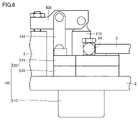
- FIG. 5 is a top view showing a state in which a fluid pipe is connected to the clamp device shown in FIGS. 1 to 4;
- FIG. 6 is a front view showing the state of FIG. 5;
- FIG. 1 is a longitudinal sectional view showing a first state (clamped state) of a clamp device (link clamp) according to this embodiment
- FIG. 2 is a top view of the clamp device shown in FIG.
- FIG. 1 is a cross-sectional view taken along line AA in FIG. 2 with the addition of a first port 30 (the position in the radial direction as viewed from the center of the cylinder is maintained).
- the clamping device is a clamping device that can fix the fixed object 1 to the base body 2 .
- a fixed position 10 of the fixed object 1 is fixed by a clamp device.
- the clamping device includes a cylinder body 100, an output member 200, a first cylinder chamber 300, a second cylinder chamber 400, a clamp arm 500, a bolt 600, and a seal member 700. and bolt 800 .
- the cylinder body 100 is fixed to the base body 2.
- Cylinder body 100 includes a body portion 110 and a flange portion 120 .
- the main body portion 110 of the cylinder main body 100 is fitted into the hole 20 provided in the base body 2 .
- the main body portion 110 has a double pipe structure of an inner peripheral pipe portion 111 and an outer peripheral pipe portion 112 .
- a flange portion 120 of the cylinder body 100 extends radially outward of the hole portion 20 and contacts the upper surface of the base body 2 .
- Flange portion 120 has a first portion 121 integrally formed with inner tube portion 111 and a second portion 122 integrally formed with outer tube portion 112 .
- the first portion 121 and the second portion 122 of the flange portion 120 are relatively positioned in the vertical direction by contacting each other from above and below.
- the upper surface of the flange portion 120 is formed flat so as to extend horizontally.
- the output member 200 is provided so as to be able to reciprocate with respect to the cylinder body 100 .
- the output member 200 includes a rod portion 210 projecting from the cylinder body 100, and a piston portion connected to the rod portion 210 and dividing the space inside the inner peripheral tube portion 111 into a first cylinder chamber 300 and a second cylinder chamber 400. 220.
- the first cylinder chamber 300 is formed in the inner space of the body portion 110 of the cylinder body 100 . More specifically, first cylinder chamber 300 is formed inside inner peripheral tube portion 111 . The first cylinder chamber 300 drives the output member 200 upward (first direction). In the state (clamped state) shown in FIG. 1, fluid pressure is supplied to the first cylinder chamber 300 .
- the second cylinder chamber 400 is formed in the internal space of the body portion 110 of the cylinder body 100 . More specifically, second cylinder chamber 400 is formed inside inner peripheral tube portion 111 . The second cylinder chamber 400 drives the output member 200 downward (second direction). In the state (clamped state) shown in FIG. 1, the fluid pressure in the second cylinder chamber 400 is discharged.
- the clamp arm 500 is rotatably attached to the upper end of the output member 200 . Furthermore, a link member 510 is attached to connect the cylinder body 100 and the clamp arm 500 . Link member 510 is rotatably connected to cylinder body 100 and clamp arm 500 .
- a link mechanism is configured by cylinder body 100 , output member 200 , clamp arm 500 , and link member 510 . As the output member 200 moves up and down, the link mechanism drives and the clamp arm 500 rotates. Thereby, clamping and unclamping operations are realized.
- the bolt 600 fixes the cylinder body 100 to the base body 2.
- the bolt 600 passes through the first portion 121 and the second portion 122 of the flange portion 120 of the cylinder body 100 from above.
- a tip (lower end) of the bolt 600 is fixed to the base body 2 .
- other fastening members such as pins may be used instead of the bolts 600 .
- the sealing member 700 includes a first sealing member 710, a second sealing member 720, and a third sealing member 730.
- the first sealing member 710 is provided on the outer circumference of the piston portion 220 of the output member 200.
- the first seal member 710 seals between the first cylinder chamber 300 and the second cylinder chamber 400 .
- the second seal member 720 is provided between the first portion 121 and the second portion 122 of the flange portion 120 of the cylinder body 100 .
- the installation position (vertical direction and radial direction) of the second seal member 720 can be changed as appropriate within the flange portion 120 .
- the second seal member 720 seals between the first cylinder chamber 300 and the outside of the cylinder body 100 .
- the first portion 121 and the second portion 122 of the flange portion 120 in the cylinder body 100 are relatively positioned along the radial direction via the second seal member 720 .
- FIG. 1 shows an ideally positioned state in which the axial centers of the inner peripheral tube portion 111 and the outer peripheral tube portion 112 are coincident. Axial misalignment between the inner peripheral pipe portion 111 and the outer peripheral pipe portion 112) is allowed as long as the flow path to the first cylinder chamber 300 is ensured.
- the third seal member 730 is provided between the rod portion 210 of the output member 200 and the cylinder body 100.
- the third seal member 730 seals between the second cylinder chamber 400 and the outside of the cylinder body 100 .
- a scraper 700A dust seal is provided above the third seal member 730 .
- FIG. 3 is a cross-sectional view around the bolt 800.
- the bolt 800 penetrates the first portion 121 and the second portion 122 of the flange portion 120 of the cylinder body 100 from below.
- a tip (upper end) of the bolt 800 is fixed to the first portion 121 .
- other fastening members such as pins may be used instead of the bolts 800 .
- a first port 30 and a second port 40 are provided on the upper surface of the cylinder body 100. As shown in FIG. The first port 30 and the second port 40 are provided in the cylinder body 100 so as to open upward. First port 30 and second port 40 are formed in first portion 121 of flange portion 120 . First port 30 and second port 40 are provided at positions closer to the axial center of output member 200 than bolts 600 and 800 . The first port 30 and the second port 40 are located on opposite sides of each other with respect to the central axis of the clamp arm 500 (the axis extending horizontally in FIG. 2). The first port 30 and the second port 40 are provided at positions that do not overlap the clamp arm 500 (clamped state, unclamped state, and intermediate states thereof) when the clamp device is viewed from above or below.
- the first port 30 is a port for supplying fluid pressure to the first cylinder chamber 300 .
- the second port 40 is a port for supplying fluid pressure to the second cylinder chamber 400 .
- the first port 30 communicates with the first cylinder chamber 300 via the inclined hole 31 and the gap 32. Fluid pressure supplied to the first port 30 can be supplied to the first cylinder chamber 300 via the inclined hole 31 and the clearance 32 . Fluid pressure supplied to the first cylinder chamber 300 can be discharged from the first port 30 via the gap 32 and the inclined hole 31 .
- the inclined hole 31 extends from the bottom of the first port 30 in a direction that obliquely intersects the upward and downward directions and reaches the gap 32 .
- the inclined hole 31 connects the first port 30 and the gap 32 .
- the inclined hole 31 is inclined radially outward of the cylinder body 100 toward the downward direction of the cylinder body 100 .
- the inclination angle of the inclined hole 31 with respect to the vertical direction is about 5° or more and 60° or less (more preferably about 15° or more and 45° or less). However, the tilt angle is not limited to the above range.
- the gap 32 is formed between the inner peripheral pipe portion 111 and the outer peripheral pipe portion 112 of the body portion 110 of the cylinder body 100 .
- the gap 32 formed in the double pipe structure of the cylinder body 100 is formed between the first seal member 710 and the second seal member 720 .
- the gap 32 is formed over the entire length of the double pipe structure of the cylinder body 100 .
- the upper end of the gap 32 communicates with the inclined hole 31.
- a lower end of the gap 32 communicates with the first cylinder chamber 300 .
- Gap 32 is formed in an annular shape so as to surround inner peripheral tube portion 111 over the entire circumference. Therefore, the radial width of the gap 32 may be smaller than the diameter of the inclined hole 31 .
- the "radial width of the gap 32" here means the radial width of the gap 32 in a state in which ideal positioning is performed such that the inner and outer tube portions 111 and 112 are aligned with each other. .
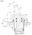
- FIG. 4 is a longitudinal sectional view showing the second state (unclamped state) of the clamping device (link clamp) according to this embodiment.
- FIG. 4 shows a cross section corresponding to the AA cross section in FIG. 2 with the addition of the second port 40 (the position in the radial direction as viewed from the center of the cylinder is maintained).
- the second port 40 communicates with the second cylinder chamber 400 through the inclined hole 41 .
- Fluid pressure supplied to the second port 40 can be supplied to the second cylinder chamber 400 via the inclined hole 41 .
- Fluid pressure supplied to the second cylinder chamber 400 can be discharged from the second port 40 via the inclined hole 41 .
- the inclined hole 41 extends from the bottom of the second port 40 in a direction that obliquely intersects the upward and downward directions and reaches the second cylinder chamber 400 .
- the inclined hole 41 connects the second port 40 and the second cylinder chamber 400 .
- the inclined hole 41 is inclined radially inwardly of the cylinder body 100 toward the downward direction of the cylinder body 100 .
- the inclination angle of the inclined hole 41 with respect to the vertical direction is about 0° or more and 45° or less (more preferably about 10° or more and 30° or less). However, the tilt angle is not limited to the above range.
- the output member 200 is driven downward by discharging the fluid pressure in the first cylinder chamber 300 and supplying the fluid pressure to the second cylinder chamber 400, thereby driving the link mechanism. Then, the clamp arm 500 rotates in the arrow B direction. As a result, the state (unclamped state) shown in FIG. 4 is realized.
- the fluid pipe 3 is connected to the first port 30 at the connecting portion 3A. Fluid pressure is supplied to and discharged from the first cylinder chamber 300 via the fluid pipe 3 .
- the fluid pipe 4 is connected to the second port 40 at the connection portion 4A. Fluid pressure is supplied to and discharged from the second cylinder chamber 400 via the fluid pipe 4 .
- a flow control valve for adjusting the flow rate of the working fluid may be provided in the connecting portions 3A and 4A.
- the first port 30 and the second port 40 are provided so as to open to the upper side of the cylinder body 100 (opposite side of the base body 2), the flow path is provided in the base body 2. No need. Therefore, the thickness of the base body 2 can be reduced. As a result, the overall size of the mechanism including the clamping device can be reduced in the vertical direction.
- the flow to the cylinder body 100 is increased.
- Processing for forming the path can be simplified.
- the size of the cylinder body 100 can be reduced by the amount of the machining margin necessary for drilling, and accordingly the size of the clamping device can be reduced.
- the outer diameter of the body portion 110 of the cylinder body 100 can be, for example, about 10 mm or more and 40 mm or less (more preferably about 15 mm or more and 30 mm or less).
- the height of the cylinder body 100 (the height from the bottom surface of the body portion 110 to the top surface of the flange portion 120) can be about 20 mm or more and 100 mm or less (more preferably about 30 mm or more and 70 mm or less).
- the dimensions of the cylinder body 100 are not limited to those described above.
- the clamping device described above can be used not only for fixing workpieces to be machined, but also for applications that require a smaller size, such as conveying devices and assembling devices.
- the application of the clamping device according to the present technology is not limited to the above.
- the link clamp having the link member 510 and the output member 200 moving up and down without turning motion has been described, but the clamping device according to the present technology is not limited to the link clamp, and the swing clamp is not limited to the link clamp. Other types of clamping devices, such as clamps, are also possible. Since the output member 200 and the clamp arm 500 do not rotate in the link clamp, the first port 30 and the second port 40 provided on the upper surface of the cylinder body 100 have a high degree of freedom in arrangement. It is possible to achieve further miniaturization of the device.
- the air cylinder using air pressure as the fluid pressure to be supplied to the first cylinder chamber 300 and the second cylinder chamber 400 has been described, but the fluid pressure cylinder according to the present technology is not limited to the air cylinder. , for example hydraulic cylinders using hydraulic pressure.
- the fluid pressure supplied to first cylinder chamber 300 and second cylinder chamber 400 is, for example, about 1 MPa or less. By limiting the fluid pressure to about 1 MPa or less, the inner peripheral tube portion 111 and the outer peripheral tube portion 112 in the body portion 110 of the cylinder body 100 can be formed thinner, so that the clamping device can be further miniaturized. is possible.
- the fluid pressure is not limited to the above range.
- the structure in which the output member 200 is driven only by fluid pressure has been described. It may be provided in the first cylinder chamber 300 or the second cylinder chamber 400 .
Landscapes
- Engineering & Computer Science (AREA)
- Mechanical Engineering (AREA)
- Physics & Mathematics (AREA)
- Fluid Mechanics (AREA)
- General Engineering & Computer Science (AREA)
- Jigs For Machine Tools (AREA)
- Actuator (AREA)
Priority Applications (3)
| Application Number | Priority Date | Filing Date | Title |
|---|---|---|---|
| CN202280050116.9A CN117642249A (zh) | 2021-07-19 | 2022-05-09 | 夹持装置 |
| EP22845676.0A EP4357072A4 (en) | 2021-07-19 | 2022-05-09 | CLAMPING DEVICE |
| US18/577,792 US20240316729A1 (en) | 2021-07-19 | 2022-05-09 | Clamping device |
Applications Claiming Priority (2)
| Application Number | Priority Date | Filing Date | Title |
|---|---|---|---|
| JP2021-118788 | 2021-07-19 | ||
| JP2021118788A JP7752401B2 (ja) | 2021-07-19 | 2021-07-19 | クランプ装置 |
Publications (1)
| Publication Number | Publication Date |
|---|---|
| WO2023002738A1 true WO2023002738A1 (ja) | 2023-01-26 |
Family
ID=84979108
Family Applications (1)
| Application Number | Title | Priority Date | Filing Date |
|---|---|---|---|
| PCT/JP2022/019643 Ceased WO2023002738A1 (ja) | 2021-07-19 | 2022-05-09 | クランプ装置 |
Country Status (5)
| Country | Link |
|---|---|
| US (1) | US20240316729A1 (https=) |
| EP (1) | EP4357072A4 (https=) |
| JP (1) | JP7752401B2 (https=) |
| CN (1) | CN117642249A (https=) |
| WO (1) | WO2023002738A1 (https=) |
Citations (9)
| Publication number | Priority date | Publication date | Assignee | Title |
|---|---|---|---|---|
| JPS4813689U (https=) | 1971-07-03 | 1973-02-15 | ||
| JPS502947U (https=) | 1973-05-14 | 1975-01-13 | ||
| JPH04175503A (ja) | 1990-11-06 | 1992-06-23 | Fujitsu Miyagi Electron:Kk | エアシリンダ |
| JPH11280709A (ja) * | 1998-03-30 | 1999-10-15 | Showa Corp | 油圧シリンダユニット |
| JP2003103425A (ja) | 2001-10-02 | 2003-04-08 | Howa Mach Ltd | リンク式クランプシリンダ |
| JP2015199139A (ja) * | 2014-04-04 | 2015-11-12 | パスカルエンジニアリング株式会社 | クランプ装置 |
| JP2015223647A (ja) * | 2014-05-27 | 2015-12-14 | パスカルエンジニアリング株式会社 | クランプ装置 |
| JP2018003958A (ja) * | 2016-07-01 | 2018-01-11 | パスカルエンジニアリング株式会社 | プッシュ型流体圧シリンダ及びリンク式クランプ装置 |
| JP2018001380A (ja) * | 2016-07-07 | 2018-01-11 | パスカルエンジニアリング株式会社 | スイング式クランプ装置 |
Family Cites Families (6)
| Publication number | Priority date | Publication date | Assignee | Title |
|---|---|---|---|---|
| JPH0623761Y2 (ja) * | 1986-12-18 | 1994-06-22 | カヤバ工業株式会社 | 油圧ユニツトの取り付け装置 |
| JPH0362204U (https=) * | 1989-10-20 | 1991-06-18 | ||
| JPH0495303U (https=) * | 1991-01-16 | 1992-08-18 | ||
| JP3849522B2 (ja) * | 2001-12-26 | 2006-11-22 | 豊和工業株式会社 | 流体圧シリンダ |
| JP5688582B2 (ja) * | 2012-07-11 | 2015-03-25 | Smc株式会社 | クランプ装置 |
| JP2015042880A (ja) * | 2013-08-26 | 2015-03-05 | パスカルエンジニアリング株式会社 | 流体圧シリンダ |
-
2021
- 2021-07-19 JP JP2021118788A patent/JP7752401B2/ja active Active
-
2022
- 2022-05-09 EP EP22845676.0A patent/EP4357072A4/en active Pending
- 2022-05-09 WO PCT/JP2022/019643 patent/WO2023002738A1/ja not_active Ceased
- 2022-05-09 US US18/577,792 patent/US20240316729A1/en active Pending
- 2022-05-09 CN CN202280050116.9A patent/CN117642249A/zh active Pending
Patent Citations (9)
| Publication number | Priority date | Publication date | Assignee | Title |
|---|---|---|---|---|
| JPS4813689U (https=) | 1971-07-03 | 1973-02-15 | ||
| JPS502947U (https=) | 1973-05-14 | 1975-01-13 | ||
| JPH04175503A (ja) | 1990-11-06 | 1992-06-23 | Fujitsu Miyagi Electron:Kk | エアシリンダ |
| JPH11280709A (ja) * | 1998-03-30 | 1999-10-15 | Showa Corp | 油圧シリンダユニット |
| JP2003103425A (ja) | 2001-10-02 | 2003-04-08 | Howa Mach Ltd | リンク式クランプシリンダ |
| JP2015199139A (ja) * | 2014-04-04 | 2015-11-12 | パスカルエンジニアリング株式会社 | クランプ装置 |
| JP2015223647A (ja) * | 2014-05-27 | 2015-12-14 | パスカルエンジニアリング株式会社 | クランプ装置 |
| JP2018003958A (ja) * | 2016-07-01 | 2018-01-11 | パスカルエンジニアリング株式会社 | プッシュ型流体圧シリンダ及びリンク式クランプ装置 |
| JP2018001380A (ja) * | 2016-07-07 | 2018-01-11 | パスカルエンジニアリング株式会社 | スイング式クランプ装置 |
Non-Patent Citations (1)
| Title |
|---|
| See also references of EP4357072A4 |
Also Published As
| Publication number | Publication date |
|---|---|
| US20240316729A1 (en) | 2024-09-26 |
| JP7752401B2 (ja) | 2025-10-10 |
| EP4357072A4 (en) | 2025-06-25 |
| JP2023014692A (ja) | 2023-01-31 |
| EP4357072A1 (en) | 2024-04-24 |
| CN117642249A (zh) | 2024-03-01 |
Similar Documents
| Publication | Publication Date | Title |
|---|---|---|
| JP5750053B2 (ja) | クランプ装置 | |
| JP2001150267A (ja) | 旋回クランプシリンダ | |
| JP2004108471A (ja) | 流量制御機構付きゲートバルブ | |
| JP2020116716A (ja) | ロボット | |
| JP2004513298A (ja) | 燃料噴射装置 | |
| CN101626867B (zh) | 联杆式夹紧装置 | |
| US11067067B2 (en) | Hydraulic device | |
| CN111836696B (zh) | 连杆式夹紧装置 | |
| WO2023002738A1 (ja) | クランプ装置 | |
| JP5746281B2 (ja) | 流体圧シリンダ | |
| WO2021210450A1 (ja) | 電動流体圧シリンダ及び移動構造体 | |
| CN113969908A (zh) | 一种高频动作增压缸 | |
| CN109882469B (zh) | 用于喷水推进装置的油缸及喷水推进装置 | |
| US10961990B2 (en) | Hydraulic device | |
| WO2011024537A1 (ja) | 流体圧シリンダ | |
| JPH051004U (ja) | 流体圧シリンダ | |
| JP2003089027A (ja) | ツイスト式クランプ装置 | |
| CN222415993U (zh) | 一种真空耙式干燥机的密封装置 | |
| CN116972250B (zh) | 高低压两通路旋转接头装置 | |
| CN222880436U (zh) | 一种具有新型定位结构的单向阀 | |
| CN219412865U (zh) | 一种自适应阀抽油泵 | |
| JPH02203083A (ja) | シール装置 | |
| JP6018942B2 (ja) | クランプ装置及びそのクランプ装置を利用したクランピングシステム | |
| CN212131457U (zh) | 高密封高压蒸汽管道铜阀盖 | |
| TWM678299U (zh) | 氣壓缸 |
Legal Events
| Date | Code | Title | Description |
|---|---|---|---|
| 121 | Ep: the epo has been informed by wipo that ep was designated in this application |
Ref document number: 22845676 Country of ref document: EP Kind code of ref document: A1 |
|
| WWE | Wipo information: entry into national phase |
Ref document number: 18577792 Country of ref document: US |
|
| WWE | Wipo information: entry into national phase |
Ref document number: 202280050116.9 Country of ref document: CN |
|
| WWE | Wipo information: entry into national phase |
Ref document number: 2022845676 Country of ref document: EP |
|
| ENP | Entry into the national phase |
Ref document number: 2022845676 Country of ref document: EP Effective date: 20240117 |
|
| NENP | Non-entry into the national phase |
Ref country code: DE |