WO2022270463A1 - 鉛蓄電池用補水栓、鉛蓄電池、組電池 - Google Patents
鉛蓄電池用補水栓、鉛蓄電池、組電池 Download PDFInfo
- Publication number
- WO2022270463A1 WO2022270463A1 PCT/JP2022/024532 JP2022024532W WO2022270463A1 WO 2022270463 A1 WO2022270463 A1 WO 2022270463A1 JP 2022024532 W JP2022024532 W JP 2022024532W WO 2022270463 A1 WO2022270463 A1 WO 2022270463A1
- Authority
- WO
- WIPO (PCT)
- Prior art keywords
- valve
- float
- lead
- partition
- water
- Prior art date
- Legal status (The legal status is an assumption and is not a legal conclusion. Google has not performed a legal analysis and makes no representation as to the accuracy of the status listed.)
- Ceased
Links
Images




Classifications
-
- H—ELECTRICITY
- H01—ELECTRIC ELEMENTS
- H01M—PROCESSES OR MEANS, e.g. BATTERIES, FOR THE DIRECT CONVERSION OF CHEMICAL ENERGY INTO ELECTRICAL ENERGY
- H01M50/00—Constructional details or processes of manufacture of the non-active parts of electrochemical cells other than fuel cells, e.g. hybrid cells
- H01M50/60—Arrangements or processes for filling or topping-up with liquids; Arrangements or processes for draining liquids from casings
- H01M50/609—Arrangements or processes for filling with liquid, e.g. electrolytes
- H01M50/627—Filling ports
- H01M50/636—Closing or sealing filling ports, e.g. using lids
- H01M50/645—Plugs
-
- Y—GENERAL TAGGING OF NEW TECHNOLOGICAL DEVELOPMENTS; GENERAL TAGGING OF CROSS-SECTIONAL TECHNOLOGIES SPANNING OVER SEVERAL SECTIONS OF THE IPC; TECHNICAL SUBJECTS COVERED BY FORMER USPC CROSS-REFERENCE ART COLLECTIONS [XRACs] AND DIGESTS
- Y02—TECHNOLOGIES OR APPLICATIONS FOR MITIGATION OR ADAPTATION AGAINST CLIMATE CHANGE
- Y02E—REDUCTION OF GREENHOUSE GAS [GHG] EMISSIONS, RELATED TO ENERGY GENERATION, TRANSMISSION OR DISTRIBUTION
- Y02E60/00—Enabling technologies; Technologies with a potential or indirect contribution to GHG emissions mitigation
- Y02E60/10—Energy storage using batteries
Definitions
- the present invention relates to a technique for replenishing water in the container of a lead-acid battery.
- Patent Document 1 describes a water faucet for a storage battery that has an automatic water stop function.
- the water supply valve for a storage battery of Patent Document 1 includes a buoyant body (float) that moves up and down following the liquid surface of the electrolyte, a connection rod (float shaft) connected to the float, and a dish-shaped valve (water stop valve). have.
- the float shaft can be displaced while sliding with the plug body.
- a water shutoff valve that displaces integrally with the float closes the water inlet to shut off the water, and refilling water is stopped.
- the present invention has been completed based on the above problems, and discloses a technique that suppresses the tilting of the float shaft due to the opening and closing of the valve hole and improves the slidability.
- a supplementary water tap for a lead-acid battery includes a plug body having a valve chamber therein, and a float valve. a float shaft fixed to the float and extending in the axial direction of the plug body; a water stop valve located in the valve chamber; and a support portion provided on the float shaft for supporting the water stop valve and, the plug body includes a pair of guide portions, the pair of guide portions having an insertion portion through which the float shaft is movably inserted in the axial direction, and the support portion in the axial direction. located on both sides of the
- tilting of the float shaft due to opening and closing of the valve hole can be suppressed, and the slidability of the float shaft with respect to the plug body can be improved.
- a supplementary water tap for a lead-acid battery includes a plug main body having a valve chamber therein, and a float valve, the tubular main body having a tubular shape extending in the axial direction, and the float
- the valve includes a float, a float shaft fixed to the float in the plug body and extending in the axial direction of the plug body, a water stop valve in the valve chamber for opening and closing a valve hole, and a support portion provided on the float shaft for supporting the water stop valve, wherein the plug body includes a pair of guide portions, the pair of guide portions allowing the float shaft to move in the axial direction. It has an insertion portion for insertion, and is positioned on both sides of the support portion in the axial direction.
- the slidability of the float shaft with respect to the pair of guide portions can be improved by suppressing the inclination (tilt) of the float shaft that accompanies the opening and closing of the valve hole. Therefore, it is possible to suppress the delay in the rise of the water stop valve with respect to the rise of the liquid level, and improve the water stoppage.
- the faucet body has a first space in which the valve chamber is provided and a second space in which the valve chamber is not provided. At least one of the pair of guide portions is provided in the first partition wall, and the float shaft supported by the pair of guide portions separates the first partition wall. and may be positioned opposite the valve chamber.
- the float shaft is positioned facing the valve chamber with the first partition therebetween, and the distance from the float shaft to the water stop valve accommodated in the valve chamber can be shortened. Therefore, when the water is stopped, the moment acting on the float shaft through the water stop valve can be reduced. By reducing the moment, the float shaft is less likely to tilt, and the slidability of the float shaft can be improved.
- the plug body has a second partition wall that partitions the second space, and the second partition wall has one end that extends from the first partition wall. and the other end is connected to the peripheral wall of the plug body, at least one of the pair of guide portions is provided at the intersection of the first partition and the second partition, and It may be fixed to both the first partition and the second partition.
- the crossing points of multiple partition walls have high rigidity because the crossing partition walls support each other.
- the surface of the float shaft is provided with a roughened surface region in which a group of fine projections is formed. good too.
- Electrolyte and water droplets adhering to the float shaft come into contact with the float shaft at the tip of each protrusion due to the action of surface tension. Since the direct contact area between the float shaft and the droplets is reduced, the electrolytic solution adhering to the float shaft is easily separated from the float shaft by vibration and gravity. Since the components contained in the electrolytic solution or the like and dirt are less likely to remain on the float shaft, the surface of the float shaft can be kept clean and the deterioration of slidability can be suppressed.
- the target of the present technology may be a lead-acid battery equipped with a lead-acid battery water faucet according to any one of (1) to (4) above.
- the lead-acid battery water tap of one of the lead-acid batteries includes a lead-acid battery water tap of the other lead-acid battery and a water supply. It may be connected via a tube.
- the replenisher By replenishing the replenisher from one end of the water supply tube, the replenisher can be supplied to each lead-acid battery up to a predetermined value.
- the replenisher can be replenished collectively for multiple lead-acid batteries.
- FIG. 1 is a plan view of an assembled battery 10 used in an electric vehicle such as an electric forklift.
- the assembled battery 10 is composed of 12 lead-acid batteries 11 arranged in 6 horizontal rows and 2 vertical rows inside the battery case 13 .
- a lead-acid battery water faucet (hereinafter also simply referred to as a 'supplementary water faucet') 20 shown in FIG.
- Water taps 20 of adjacent lead-acid batteries 11 are connected via water supply tubes 12 .
- a water tank (not shown) to one end 12a of the water supply tube 12 and pumping water (an example of a "replenisher"), the 12 lead-acid batteries 11 can be supplied with water at once.
- the supplementary water tap 20 will be described below with reference to FIGS. 2 to 10.
- FIG. The supplementary water tap 20 includes a tap main body 30 and a float valve 60. - ⁇
- FIG. 2 is a perspective view of the replenishment tap 20, and FIG. 3 is a front view.
- the plug body 30 is made of synthetic resin such as ABS, and has a substantially cylindrical shape extending in the axial direction. 2 and 3 show a state in which the axial direction of the plug body 30 is oriented vertically. 8, the axial direction is the direction of the axis L of the plug body 30.
- a brim portion 31 is the thickest portion in the horizontal direction of the plug body 30 .
- a ring-shaped rubber packing 32 is arranged along the outer circumference of the plug body 30 below the collar portion 31 .
- the rubber packing 32 is in tight contact with both the lower surface of the collar portion 31 and the upper surface of the battery lid to seal around the liquid port.
- the portion of the water replenishing tap 20 closer to the plug lid portion 37 than the rubber packing 32 is exposed above the upper surface of the battery lid, and the other portion is inserted into the liquid port of the battery lid and positioned inside the battery case. .
- a water supply port 33 (see FIG. 8) is provided on the upper surface of the flange portion 31, and a three-pronged water supply pipe joint 34 is connected to the water supply port 33.
- the water supply tubes 12 connected to the water supply pipe joints 34 connect the water supply pipe joints 34 of the adjacent lead-acid batteries 11 to each other.
- a semi-cylindrical portion 35 is erected on the upper surface of the brim portion 31 at a position on the front left side in FIG.
- the upper end of the semi-cylindrical portion 35 forms an opening 35a having a semi-circular opening edge.
- a plug lid portion 37 is connected via a hinge 36 to the chord portion of the opening edge.
- the opening 35a can be opened or closed by rotating the stopper 37 about the hinge 36. As shown in FIG.
- the plug body 30 has three partition walls (first partition wall 41 to third partition wall 43).
- the three partition walls 41-43 are integral with the plug body 30.
- the first partition 41 extends substantially parallel to the axial direction inside the plug body 30 .
- both ends of the first partition 41 are connected to the peripheral wall 38, respectively, and the first partition 41 partitions the internal space of the plug body 30 into two spaces.
- the second partition 42 and the third partition 43 are partitions extending substantially parallel to the axial direction inside the plug body 30 .
- the second partition 42 and the third partition 43 are arranged in each of the two internal spaces of the plug body 30 partitioned by the first partition 41 .
- the second partition 42 and the third partition 43 extend from the peripheral wall 38 toward the first partition 41 and are connected to the first partition 41 .
- the second partition 42 and the third partition 43 further partition the internal space of the plug body 30 divided into two by the first partition.
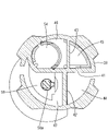
- FIG. 6 is a diagram schematically showing the positions of the first partition wall 41 to the third partition wall 43 superimposed on the plan view of the plug body 30.
- the internal space of the replenishment tap 20 partitioned into four by the first partition 41 to the third partition 43 is arranged counterclockwise from the lower right in FIGS. (2) front chamber 45, (3) water stop chamber 46, and (4) refilling chamber 47.
- the space on the side where the front chamber 45 and the water stop chamber 46 are provided is the “second 1 space”
- the space on the side where the refilling chamber 47 and the measurement chamber 44 are provided is the “second space”.
- each of the partitions 41-43 has a gap or a slit, and has a structure in which water can pass through the four divided spaces 44-47.
- the water in the front chamber 45 can flow into the water stop chamber 46 through a gap 52 formed below the end 49a of the first partition 41 (partition wall 49). It has become.
- a slit 39 extending over the water stop chamber 46 and the water replenishing chamber 47 is provided through the first partition wall 41 .
- FIG. 7 is a cross-sectional view along line CC in FIG. Points b to f in FIG. 7 respectively correspond to the positions of points b to f in FIG. 6 on the plan view. Arrows connecting the points in FIGS. 6 and 7 indicate the path of water inside the water retaining valve. The spaces 44 to 47 and the paths of water will be described below.
- the water supplied from the water supply tube 12 to the water supply port 33 passes through the water path inside the water replenishing valve, reaches the replenishing water chamber 47, and finally refills the battery tank.
- the water supply port 33 side is defined as the upstream side
- the water replenishing chamber 47 side is defined as the downstream side with reference to an arbitrary point in the water path.
- the measurement chamber 44 is a space surrounded by the peripheral wall 38, the first partition 41 and the second partition 42, and is located on the lower right in FIGS.
- the measurement chamber 44 does not have a ceiling surface and a bottom surface, and penetrates the supplementary water tap 20 in the axial direction.
- a portion of the measurement chamber 44 closer to the stopper lid portion 37 than the collar portion 31 is part of the internal space of the semi-cylindrical portion 35 .
- the measurement chamber 44 functions as an insertion port into which a specific gravity meter is inserted when measuring the specific gravity of the electrolyte. When a rod-shaped specific gravity meter is inserted into the specific gravity measurement port through the opening 35a of the semi-cylindrical portion 35, the tip of the specific gravity meter reaches the electrolyte, and the specific gravity can be measured.
- the front chamber 45 is a space surrounded by the peripheral wall 38, the first partition 41 and the third partition 43, and is located on the upper right in FIGS.
- the front chamber 45 communicates with the water supply port 33, and the water supplied to the water supply port 33 flows into and temporarily stays therein. Specifically, as shown in FIGS. 6 and 7, water supplied from the water supply tube 12 (point a) passes through the water supply pipe joint 34 (point b) and flows into the front chamber 45 from the water supply port 33. (point c).
- a guide passage 48 is provided at the boundary between the front chamber 45 and the water stop chamber 46 .
- the guide passage 48 is formed by a partition wall 49 (part of the first partition wall 41) and a side wall 50 of the valve chamber 54.
- a gap 52 is provided between the end portion 49 a of the partition wall 49 and the bottom surface 51 of the plug body 30 , and this gap 52 serves as the entrance of the guide passage 48 .
- Water entering the guide passage 48 from the inlet (point d) flows through the guide passage 48 toward the downstream side, and then passes through an inlet 53 penetrating the upper portion of the side wall 50 of the valve chamber 54 and into the valve chamber 54 . (point e).
- the water stop chamber 46 is a space surrounded by the peripheral wall 38, the first partition 41 and the third partition 43, and is located on the upper left in FIGS.
- the water stop chamber 46 has the guide passage 48 and the valve chamber 54 described above.
- the valve chamber 54 has a cylindrical shape with an axis in the vertical direction.
- the valve chamber 54 accommodates therein a water stop valve 62 to be described later.
- a ceiling wall of the valve chamber 54 is provided with a valve hole 55 penetrating therethrough in the axial direction.
- the ceiling wall of the valve chamber 54 has a tapered shape that narrows toward the downstream side, and the center of the ceiling wall is the valve hole 55 .
- the water that has flowed into the valve chamber 54 passes through the valve hole 55 and flows out from the valve chamber 54 to the space above it.
- the water replenishment chamber 47 is a space surrounded by the peripheral wall 38, the first partition 41 and the second partition 42, and is located at the lower left in FIGS. 4 to 6.
- the refilling chamber 47 has an opening downward.
- the side of the replenishing water chamber 47 on the stopper lid portion 37 side is also the internal space of the semi-cylindrical portion 35 .
- the water flowing out from the valve hole 55 into the upper space of the valve chamber 54 flows horizontally over the water shut-off chamber 46, enters the replenishing water chamber 47, drops downward, and is replenished into the container (point f). .
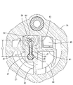
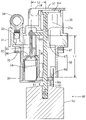
- FIG. 8 and 9 are DD cross-sectional views of the supplementary water tap 20.
- FIG. The refilling chamber 47 is provided with a pair of guide portions 56 spaced apart in the axial direction (vertical direction).
- the upper part is the first guide part 57 and the lower part is the second guide part 58 .
- the distance between the first guide portion 57 and the second guide portion 58 is defined as "L1".
- the first guide part 57 is located inside the refilling chamber 47.
- the first guide portion 57 is provided at an intersection position where the first partition 41 and the second partition 42 intersect in plan view.
- the first partition 41 and the second partition 42 intersect at approximately the center of the plug main body 30.
- a first guide portion 57 is provided at the intersection position J1 on the left side.
- the first guide portion 57 has a rectangular shape in plan view, as shown in FIG.
- the first guide portion 57 has its upper end face fixed (coupled) to the first partition wall 41 and its right end face fixed (coupled) to the second end face 42 .
- the second guide part 58 is attached to the wall surface of the first partition 41 on the water replenishing chamber 47 side.
- the second guide portion 58 has a substantially fan-shaped plate shape.
- the second guide portion 58 extends horizontally from the lower end of the first partition wall 41 .
- the first guide portion 57 and the second guide portion 58 are provided with circular first insertion holes 57a and second insertion holes 58a, respectively, which penetrate in the vertical direction.
- a float shaft 61 is inserted through the two insertion holes 57a and 58a.
- the float shaft 61 reciprocates vertically while being kept substantially vertical by the guide action of the two insertion holes 57a and 58a. Further, movement in the direction perpendicular to the axial direction (horizontal direction) is restricted by the guiding action of the two insertion holes 57a and 58a.
- Both the first guide part 57 and the second guide part 58 are provided in the first partition wall 41 inside the refilling chamber 47 .
- a water stop chamber 46 having a valve chamber 54 is arranged on the opposite side of the first partition 41 . Therefore, the float shaft 61 held by the pair of guide portions 56 is positioned to face the valve chamber 54 with the first partition 41 therebetween.
- the distance between the float shaft 61 and the water stop valve 62 housed in the valve chamber 54 is defined as "L2" (see FIGS. 4 and 8).
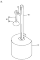
- FIG. 10 shows an overall view of the float valve 60 .
- the float valve 60 is formed by connecting a float shaft 61, a water stop valve 62, and a float 63 integrally. A portion of the float valve 60 other than the float 63 is housed inside the plug body 30 (see FIGS. 2 and 3). The float valve 60 is not fixed to the plug body 30 and can move up and down with respect to the plug body 30 .
- the float shaft 61 is supported in the refilling chamber 47 by two guides 57 and 58 with its axis directed vertically.
- the float shaft 61 extends downward through the second guide portion 58 and protrudes downward from the bottom surface 51 of the plug body 30 .
- the outer peripheral surface of the float shaft 61 is textured to form a surface-roughened area with many minute projections.
- the contact area with the droplets becomes small. As a result, the adhering droplets are likely to drop due to vibration or gravity.
- the float shaft 61 has a support portion 64 on its outer peripheral surface.
- the support portion 64 horizontally protrudes from the float shaft 61 between the first guide portion 57 and the second guide portion 58 .
- the support portion 64 penetrates through a slit 39 provided through the first partition wall 41 forming a boundary between the refilling chamber 47 and the water stop chamber 46 .
- the slit 39 is elongated in the vertical direction and functions as a guide groove that guides the vertical movement of the support portion 64 .
- the tip of the support portion 64 extends to the upper space of the valve chamber 54 and supports the water stop valve 62 housed in the valve chamber 54 in a suspended manner.
- the water stop valve 62 consists of a valve shaft 65 and a valve body 66 .
- the valve shaft 65 extends in the same vertical direction as the axial direction of the plug body 30 and vertically penetrates the valve hole 55 in the ceiling surface of the valve chamber 54 .
- the upper end of the valve shaft 65 is fixed to the support portion 64, and the valve body 66 is fixed to the lower end.
- the valve body 66 has a size that allows close contact with the tapered surface of the valve hole 55 without a gap.
- the valve hole 55 has a tapered shape that narrows toward the downstream side, and the valve body 66 has a substantially hemispherical shape that narrows on the side that contacts the valve hole 55 .
- the float 63 is a substantially cylindrical floating body made of hollow or foamed synthetic resin.
- the lower end of the float shaft 61 is inserted into and fixed to the float 63 .
- the float 63 floats on the liquid surface of the electrolytic solution in the container and moves up and down following the liquid surface.
- the range in which the float valve 60 moves up and down with respect to the plug body 30 is between the lower limit position (Fig. 8) and the upper limit position (Fig. 9).
- the support portion 64 contacts the lower end of the slit 39 and the water stop valve 62 contacts the bottom surface of the valve chamber 54 .
- valve body 66 When the float valve 60 is displaced from the lower limit position to the upper limit position, the valve body 66 abuts against the valve hole 55 from below to block the valve hole 55 .
- the refilling tap 20 automatically stops refilling water when the liquid level reaches a predetermined height.
- the frictional resistance against the guide portions 57 and 58 can be reduced when the float shaft 61 moves in the axial direction (vertical direction) of the plug body 30. Thereby, the slidability of the float shaft 61 can be improved.
- the ability of the float valve 60 to follow up and down movements of the liquid surface is enhanced, so that the valve body 66 closes the valve hole 55 in accordance with the timing when the liquid surface of the electrolytic solution reaches the target height in the container. It is possible to prevent the liquid level of the electrolytic solution from exceeding the target height.
- a pair of guide portions 56 (a first guide portion 57 and a second guide portion 58) are arranged in the valve chamber 54 with the first partition 41 interposed therebetween. are located opposite each other. Therefore, the distance L2 from the float shaft 61 held by the pair of guide portions 56 to the water stop valve 62 housed in the valve chamber 54 can be reduced. As a result, when the valve body 66 closes the valve hole 55 to stop water, the moment acting on the float shaft 61 through the water stop valve 62 is reduced. By reducing the moment, the inclination of the float shaft 61 can be further suppressed.
- the second partition 42 has one end connected to the first partition 41 and the other end connected to the peripheral wall 38 of the plug body 30 .
- the first guide portion 57 is fixed to both the first partition 41 and the second partition 42 at the intersection of the first partition 41 and the second partition 42 .
- the first guide portion 57 is less likely to deform. By suppressing the deformation of the first guide portion 57, the inclination of the float shaft 61 can be further suppressed.
- the surface of the float shaft 61 is a surface-roughened region in which a group of fine protrusions is formed.
- droplets of the electrolytic solution or water adhering to the surface of the float shaft 61 come into contact with the float shaft 61 at the tip of each protrusion due to the function of surface tension. Since the direct contact area between the float shaft 61 and the droplets is reduced, the droplets are more likely to separate from the float shaft 61, and the components and dirt contained in the droplets are less likely to remain. As a result, the surface of the float shaft 61 can be kept clean, and deterioration of slidability can be suppressed.
- the assembled battery 10 used for an electric forklift is exemplified.
- the assembled battery 10 can also be used for an electric trolley, an aerial work vehicle, and the like.
- the application of the assembled battery 10 is not limited to a mobile object such as an electric vehicle. It can also be used for stationary applications such as uninterruptible power supplies and power storage devices for power generation systems.
- the valve body 66 has a hemispherical shape that widens downward.
- the shape of the valve hole 55 is a tapered shape that narrows upward.
- the shapes of the valve body 66 and the valve hole 55 are not limited to these, and other shapes may be used as long as the valve body 66 can close the valve hole 55 to stop water.
- the valve body 66 may have a hemispherical shape that widens upward, and the valve hole 55 may have a tapered shape that narrows downward.
- the insertion holes 57a and 58a of the guide portions 57 and 58 are circular, but may be elliptical, polygonal or other shapes.
- the support portion 64 extends horizontally from the float shaft 61, but the extending direction does not have to be horizontal. For example, it may extend obliquely upward or obliquely downward. Further, the shape of the support portion 64 does not have to be a straight rod shape. For example, it may have a curved shape or a crank shape.
- the first guide portion 57 arranged above is provided at the intersection of the two partition walls (the first partition wall 41 and the second partition wall 42).
- An example is shown.
- the present invention is not limited to this, and the lower second guide portion 58 may be provided at the intersection of the two partition walls, or the pair of guide portions 56 may be provided at the intersection of the two partition walls. may be provided in
- the rod-shaped float shaft 61 is inserted through the insertion holes provided through the pair of guide portions 56, thereby guiding the vertical direction and restricting the horizontal displacement.
- the shapes of the float shaft 61 and the pair of guide portions 56 are not limited to this, and may be other shapes.
- the pair of guide portions 56 have grooves that are recessed along the vertical direction, and the projections formed on the float shaft 61 are fitted into the grooves, thereby providing vertical guidance and horizontal movement. may be regulated.
- the circular first insertion hole 57a and the circular second insertion hole 58a are shown as an example of the insertion portion through which the float shaft is axially movably inserted.
- the shape of the insertion portion is not limited to a hole shape. For example, it may have a groove shape.
Landscapes
- Chemical & Material Sciences (AREA)
- Chemical Kinetics & Catalysis (AREA)
- Electrochemistry (AREA)
- General Chemical & Material Sciences (AREA)
- Filling, Topping-Up Batteries (AREA)
Priority Applications (2)
| Application Number | Priority Date | Filing Date | Title |
|---|---|---|---|
| JP2023530459A JP7833121B2 (ja) | 2021-06-22 | 2022-06-20 | 鉛蓄電池用補水栓、鉛蓄電池、組電池 |
| CN202280043929.5A CN117546359A (zh) | 2021-06-22 | 2022-06-20 | 铅蓄电池用补水栓、铅蓄电池、电池组 |
Applications Claiming Priority (2)
| Application Number | Priority Date | Filing Date | Title |
|---|---|---|---|
| JP2021-103064 | 2021-06-22 | ||
| JP2021103064 | 2021-06-22 |
Publications (1)
| Publication Number | Publication Date |
|---|---|
| WO2022270463A1 true WO2022270463A1 (ja) | 2022-12-29 |
Family
ID=84545683
Family Applications (1)
| Application Number | Title | Priority Date | Filing Date |
|---|---|---|---|
| PCT/JP2022/024532 Ceased WO2022270463A1 (ja) | 2021-06-22 | 2022-06-20 | 鉛蓄電池用補水栓、鉛蓄電池、組電池 |
Country Status (3)
| Country | Link |
|---|---|
| JP (1) | JP7833121B2 (https=) |
| CN (1) | CN117546359A (https=) |
| WO (1) | WO2022270463A1 (https=) |
Citations (5)
| Publication number | Priority date | Publication date | Assignee | Title |
|---|---|---|---|---|
| JPH0291154U (https=) * | 1988-12-28 | 1990-07-19 | ||
| US5862830A (en) * | 1995-07-25 | 1999-01-26 | Landau Systemtechnik Gmbh | Water replenishing plug for a battery containing a liquid electrolyte |
| JP2003346782A (ja) * | 2002-05-29 | 2003-12-05 | Yuasa Corp | 液式電池用一括補水装置の補水栓 |
| CN102691824A (zh) * | 2012-06-15 | 2012-09-26 | 浙江天能电池(江苏)有限公司 | 定量补水的电池阀 |
| WO2013073102A1 (ja) * | 2011-11-17 | 2013-05-23 | 株式会社Gsユアサ | 蓄電池用補水栓 |
-
2022
- 2022-06-20 CN CN202280043929.5A patent/CN117546359A/zh active Pending
- 2022-06-20 WO PCT/JP2022/024532 patent/WO2022270463A1/ja not_active Ceased
- 2022-06-20 JP JP2023530459A patent/JP7833121B2/ja active Active
Patent Citations (5)
| Publication number | Priority date | Publication date | Assignee | Title |
|---|---|---|---|---|
| JPH0291154U (https=) * | 1988-12-28 | 1990-07-19 | ||
| US5862830A (en) * | 1995-07-25 | 1999-01-26 | Landau Systemtechnik Gmbh | Water replenishing plug for a battery containing a liquid electrolyte |
| JP2003346782A (ja) * | 2002-05-29 | 2003-12-05 | Yuasa Corp | 液式電池用一括補水装置の補水栓 |
| WO2013073102A1 (ja) * | 2011-11-17 | 2013-05-23 | 株式会社Gsユアサ | 蓄電池用補水栓 |
| CN102691824A (zh) * | 2012-06-15 | 2012-09-26 | 浙江天能电池(江苏)有限公司 | 定量补水的电池阀 |
Also Published As
| Publication number | Publication date |
|---|---|
| CN117546359A (zh) | 2024-02-09 |
| JP7833121B2 (ja) | 2026-03-19 |
| JPWO2022270463A1 (https=) | 2022-12-29 |
Similar Documents
| Publication | Publication Date | Title |
|---|---|---|
| CN109974273B (zh) | 用于空气处理设备的接水盘组件及空气处理设备 | |
| WO2022270463A1 (ja) | 鉛蓄電池用補水栓、鉛蓄電池、組電池 | |
| JP6024668B2 (ja) | 蓄電池用補水栓 | |
| JP2024050870A (ja) | 補水栓 | |
| WO2022270465A1 (ja) | 鉛蓄電池用補水栓、鉛蓄電池、組電池 | |
| WO2022270464A1 (ja) | 鉛蓄電池用補水栓、鉛蓄電池、組電池 | |
| JP2017078399A (ja) | エクスパンションタンク | |
| CN205398835U (zh) | 一种加弹机的上油装置 | |
| JP4492441B2 (ja) | 気液分離装置 | |
| RU7088U1 (ru) | Топливный бак для хранения и подачи жидкого топлива в условиях невесомости | |
| CN209103160U (zh) | 液位控制器及其液位控制系统 | |
| JP6401033B2 (ja) | 燃料電池式産業車両 | |
| KR20120132029A (ko) | 냉온수기의 물 분리대 | |
| CN205244574U (zh) | 一种可以实现任意水位控制的浮球阀装置 | |
| CN112148040A (zh) | 一种可自动保持液体体积恒定的液体实验装置 | |
| US20200361799A1 (en) | Hydrogen water generator | |
| JPH0610626Y2 (ja) | 蓄電池用補水栓 | |
| JPS5834698Y2 (ja) | 蓄電池用液口栓 | |
| JP7442830B2 (ja) | ペット用給水器 | |
| JP2002083584A (ja) | バッテリー補充液注入用チューブ、および同チューブを使用したバッテリー補充液自動注入装置、ならびにその装置を使用したバッテリー補充液自動注入方法 | |
| CN224050680U (zh) | 一种专用于燃气模块炉的补水排气装置 | |
| CN209430835U (zh) | 一种新型节流阀门 | |
| CN209100749U (zh) | 液位控制器及其液位控制系统 | |
| CN109616609A (zh) | 电解液导流装置及蓄电池 | |
| KR101525322B1 (ko) | 상부 기체 누출 지연형 안전주입탱크 |
Legal Events
| Date | Code | Title | Description |
|---|---|---|---|
| 121 | Ep: the epo has been informed by wipo that ep was designated in this application |
Ref document number: 22828380 Country of ref document: EP Kind code of ref document: A1 |
|
| WWE | Wipo information: entry into national phase |
Ref document number: 2023530459 Country of ref document: JP |
|
| WWE | Wipo information: entry into national phase |
Ref document number: 2301008285 Country of ref document: TH |
|
| WWE | Wipo information: entry into national phase |
Ref document number: 202280043929.5 Country of ref document: CN |
|
| NENP | Non-entry into the national phase |
Ref country code: DE |
|
| 122 | Ep: pct application non-entry in european phase |
Ref document number: 22828380 Country of ref document: EP Kind code of ref document: A1 |