WO2022270280A1 - 円筒形電池 - Google Patents
円筒形電池 Download PDFInfo
- Publication number
- WO2022270280A1 WO2022270280A1 PCT/JP2022/022721 JP2022022721W WO2022270280A1 WO 2022270280 A1 WO2022270280 A1 WO 2022270280A1 JP 2022022721 W JP2022022721 W JP 2022022721W WO 2022270280 A1 WO2022270280 A1 WO 2022270280A1
- Authority
- WO
- WIPO (PCT)
- Prior art keywords
- electrode
- insulating plate
- positive electrode
- current collector
- collector plate
- Prior art date
- Legal status (The legal status is an assumption and is not a legal conclusion. Google has not performed a legal analysis and makes no representation as to the accuracy of the status listed.)
- Ceased
Links
Images


Classifications
-
- H—ELECTRICITY
- H01—ELECTRIC ELEMENTS
- H01M—PROCESSES OR MEANS, e.g. BATTERIES, FOR THE DIRECT CONVERSION OF CHEMICAL ENERGY INTO ELECTRICAL ENERGY
- H01M10/00—Secondary cells; Manufacture thereof
- H01M10/04—Construction or manufacture in general
-
- H—ELECTRICITY
- H01—ELECTRIC ELEMENTS
- H01M—PROCESSES OR MEANS, e.g. BATTERIES, FOR THE DIRECT CONVERSION OF CHEMICAL ENERGY INTO ELECTRICAL ENERGY
- H01M50/00—Constructional details or processes of manufacture of the non-active parts of electrochemical cells other than fuel cells, e.g. hybrid cells
- H01M50/10—Primary casings; Jackets or wrappings
- H01M50/102—Primary casings; Jackets or wrappings characterised by their shape or physical structure
- H01M50/107—Primary casings; Jackets or wrappings characterised by their shape or physical structure having curved cross-section, e.g. round or elliptic
-
- H—ELECTRICITY
- H01—ELECTRIC ELEMENTS
- H01M—PROCESSES OR MEANS, e.g. BATTERIES, FOR THE DIRECT CONVERSION OF CHEMICAL ENERGY INTO ELECTRICAL ENERGY
- H01M50/00—Constructional details or processes of manufacture of the non-active parts of electrochemical cells other than fuel cells, e.g. hybrid cells
- H01M50/10—Primary casings; Jackets or wrappings
- H01M50/147—Lids or covers
- H01M50/148—Lids or covers characterised by their shape
- H01M50/152—Lids or covers characterised by their shape for cells having curved cross-section, e.g. round or elliptic
-
- H—ELECTRICITY
- H01—ELECTRIC ELEMENTS
- H01M—PROCESSES OR MEANS, e.g. BATTERIES, FOR THE DIRECT CONVERSION OF CHEMICAL ENERGY INTO ELECTRICAL ENERGY
- H01M50/00—Constructional details or processes of manufacture of the non-active parts of electrochemical cells other than fuel cells, e.g. hybrid cells
- H01M50/50—Current conducting connections for cells or batteries
- H01M50/531—Electrode connections inside a battery casing
- H01M50/533—Electrode connections inside a battery casing characterised by the shape of the leads or tabs
-
- H—ELECTRICITY
- H01—ELECTRIC ELEMENTS
- H01M—PROCESSES OR MEANS, e.g. BATTERIES, FOR THE DIRECT CONVERSION OF CHEMICAL ENERGY INTO ELECTRICAL ENERGY
- H01M50/00—Constructional details or processes of manufacture of the non-active parts of electrochemical cells other than fuel cells, e.g. hybrid cells
- H01M50/50—Current conducting connections for cells or batteries
- H01M50/543—Terminals
- H01M50/547—Terminals characterised by the disposition of the terminals on the cells
- H01M50/548—Terminals characterised by the disposition of the terminals on the cells on opposite sides of the cell
-
- H—ELECTRICITY
- H01—ELECTRIC ELEMENTS
- H01M—PROCESSES OR MEANS, e.g. BATTERIES, FOR THE DIRECT CONVERSION OF CHEMICAL ENERGY INTO ELECTRICAL ENERGY
- H01M50/00—Constructional details or processes of manufacture of the non-active parts of electrochemical cells other than fuel cells, e.g. hybrid cells
- H01M50/50—Current conducting connections for cells or batteries
- H01M50/572—Means for preventing undesired use or discharge
- H01M50/584—Means for preventing undesired use or discharge for preventing incorrect connections inside or outside the batteries
- H01M50/59—Means for preventing undesired use or discharge for preventing incorrect connections inside or outside the batteries characterised by the protection means
- H01M50/593—Spacers; Insulating plates
-
- Y—GENERAL TAGGING OF NEW TECHNOLOGICAL DEVELOPMENTS; GENERAL TAGGING OF CROSS-SECTIONAL TECHNOLOGIES SPANNING OVER SEVERAL SECTIONS OF THE IPC; TECHNICAL SUBJECTS COVERED BY FORMER USPC CROSS-REFERENCE ART COLLECTIONS [XRACs] AND DIGESTS
- Y02—TECHNOLOGIES OR APPLICATIONS FOR MITIGATION OR ADAPTATION AGAINST CLIMATE CHANGE
- Y02E—REDUCTION OF GREENHOUSE GAS [GHG] EMISSIONS, RELATED TO ENERGY GENERATION, TRANSMISSION OR DISTRIBUTION
- Y02E60/00—Enabling technologies; Technologies with a potential or indirect contribution to GHG emissions mitigation
- Y02E60/10—Energy storage using batteries
-
- Y—GENERAL TAGGING OF NEW TECHNOLOGICAL DEVELOPMENTS; GENERAL TAGGING OF CROSS-SECTIONAL TECHNOLOGIES SPANNING OVER SEVERAL SECTIONS OF THE IPC; TECHNICAL SUBJECTS COVERED BY FORMER USPC CROSS-REFERENCE ART COLLECTIONS [XRACs] AND DIGESTS
- Y02—TECHNOLOGIES OR APPLICATIONS FOR MITIGATION OR ADAPTATION AGAINST CLIMATE CHANGE
- Y02P—CLIMATE CHANGE MITIGATION TECHNOLOGIES IN THE PRODUCTION OR PROCESSING OF GOODS
- Y02P70/00—Climate change mitigation technologies in the production process for final industrial or consumer products
- Y02P70/50—Manufacturing or production processes characterised by the final manufactured product
Definitions
- the present disclosure relates to cylindrical batteries.
- Cylindrical batteries are used not only for mobile devices, but also for vehicles in recent years, and there is a demand for even higher output. Cylindrical batteries are characterized by their resistance to impact and their ease of modularization. Cylindrical batteries generally include a wound electrode body, a bottomed cylindrical outer can containing the electrode body, and a sealing body that closes the opening of the outer can. Further, an electrode lead is provided in the outer can of the cylindrical battery for electrically connecting the electrode constituting the electrode body and the current collecting plate of the sealing body. The current collection structure from the electrode body is an important factor in lowering the resistance of the cylindrical battery and improving the output characteristics.
- a cylindrical battery generally includes an insulating plate placed between an electrode body and a sealing body. The interposition of this insulating plate between the electrode lead and the counter electrode (negative electrode when the electrode lead is the positive electrode lead) prevents occurrence of an internal short circuit.
- a first insulating plate having a plurality of positive electrode leads and arranged on an electrode body, a collector plate arranged on the first insulating plate, and a first insulating plate of the collector plate are disclosed.
- a cylindrical battery is disclosed that includes a second insulating plate positioned to abut against the opposing surface of the plate.
- a plurality of positive electrode leads are electrically connected to the sealing member via a collector plate arranged on the first insulating plate.
- the sealing body functions as a positive electrode external terminal
- the outer can functions as a negative electrode external terminal, so that contact between the sealing body and the electrode lead connected to the sealing body and the outer can is reliably prevented.
- contact between the sealing body and the electrode lead connected to the sealing body and the outer is reliably prevented.
- An object of the present disclosure is to provide a cylindrical battery that has a simplified and simple structure and that can more reliably prevent contact between the electrode lead connected to the current collector plate of the sealing body and the outer can that is the counter electrode. It is to be.
- a cylindrical battery which is one aspect of the present disclosure, has an electrode body in which a first electrode and a second electrode are wound with a separator interposed therebetween, and a grooved portion formed in a side wall to accommodate the electrode body.
- a bottom cylindrical outer can a sealing member that has a current collector plate and is supported by the grooved portion to close the opening of the outer can;
- An electrode lead that directly connects the electrode and the current collecting plate of the sealing body, and an upper insulating plate disposed between the electrode body and the sealing body, wherein the upper insulating plate comprises a first insulating plate and a first insulating plate.
- a second insulating plate disposed between the grooved portion and the electrode lead; the electrode lead is bent in the central axis direction of the electrode body; 2 insulating plates.
- cylindrical battery according to the present disclosure has a simplified and simple structure, it is possible to more reliably prevent contact between the electrode lead connected to the current collector plate of the sealing member and the outer can serving as the counter electrode. can.
- FIG. 1 is a cross-sectional view of a cylindrical battery that is an example of an embodiment
- FIG. FIG. 4 is a front view of electrodes to which electrode leads are connected
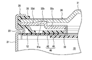
- FIG. 2 is an enlarged view of part A in FIG. 1
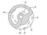
- FIG. 4 is a plan view of the first insulating plate, showing a state in which the first insulating plate is arranged on the electrode body
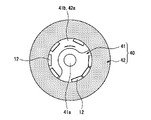
- FIG. 11 is a plan view of the second insulating plate, showing a state where the second insulating plate is arranged on the electrode body;
- FIG. 1 is a cross-sectional view of a cylindrical battery 1 that is an example of an embodiment.
- the cylindrical battery 1 includes an electrode body 10 , a bottomed cylindrical outer can 20 that houses the electrode body 10 , and a sealing body 30 that closes the opening of the outer can 20 .
- the outer can 20 contains the electrode body 10 and the electrolytic solution.
- the electrolytic solution may be an aqueous electrolytic solution, but a non-aqueous electrolytic solution is used in this embodiment.
- the outer can 20 has a grooved portion 23 formed in the side wall 21 , and the sealing member 30 is supported by the grooved portion 23 to close the opening of the outer can 20 .
- the sealing body 30 side of the cylindrical battery 1 is referred to as the upper side
- the can bottom 22 side of the outer can 20 is referred to as the lower side.
- Cylindrical battery 1 further extends from a position facing grooved portion 23 on the outer peripheral side of electrode body 10, and an electrode lead that directly connects the first electrode constituting electrode body 10 and current collector plate 32 of sealing body 30. and an upper insulating plate 40 arranged between the electrode body 10 and the sealing body 30 .
- the electrode body 10 is a wound electrode body in which a first electrode and a second electrode are wound with a separator interposed therebetween.
- the second electrode is the negative electrode and the electrode lead is the positive lead 12 .
- Cylindrical battery 1 may have a lower insulating plate disposed between electrode body 10 and can bottom 22 .
- the positive electrode lead 12 electrically connects the positive electrode 11 and the sealing member 30
- the negative electrode lead electrically connects the negative electrode and the outer can 20
- the sealing member 30 functions as a positive electrode external terminal
- the outer can 20 functions as a negative electrode external terminal.
- the upper insulating plate 40 prevents the positive electrode 11 and the positive electrode lead 12 from contacting the outer can 20 and also prevents the positive electrode lead 12 from contacting the negative electrode of the electrode body 10 .
- the electrode body 10 includes a positive electrode 11, a negative electrode, and a separator, and has a wound structure in which the positive electrode 11 and the negative electrode are spirally wound with the separator interposed therebetween.
- the positive electrode 11 , the negative electrode, and the separator are all strip-shaped elongated bodies, and are alternately laminated in the radial direction of the electrode body 14 by being spirally wound.
- the negative electrode is formed to have a size one size larger than that of the positive electrode 11 in order to prevent deposition of lithium. That is, the negative electrode is formed longer than the positive electrode 11 in the longitudinal direction and the width direction (transverse direction).
- the separator is at least one size larger than the positive electrode 11 and, for example, two separators are arranged so as to sandwich the positive electrode 11 .
- the positive electrode 11 has a positive electrode core and a positive electrode mixture layer formed on at least one surface of the core.
- a foil of a metal such as aluminum or an aluminum alloy that is stable in the potential range of the positive electrode 11, a film in which the metal is arranged on the surface layer, or the like can be used.
- the positive electrode material mixture layer contains a positive electrode active material, a conductive agent such as acetylene black, and a binder such as polyvinylidene fluoride, and is preferably formed on both surfaces of the positive electrode core.
- a lithium-transition metal composite oxide is used as the positive electrode active material.
- the positive electrode lead 12 is connected to the positive electrode 11 and is preferably directly joined to the positive electrode core by welding or the like.
- the negative electrode has a negative electrode core and a negative electrode mixture layer formed on at least one surface of the core.
- a foil of a metal such as copper or a copper alloy that is stable in the potential range of the negative electrode, a film having the metal on the surface layer, or the like can be used.
- the negative electrode mixture layer contains a negative electrode active material and a binder such as styrene-butadiene rubber (SBR), and is preferably formed on both sides of the negative electrode core.
- SBR styrene-butadiene rubber
- Graphite, a silicon-containing compound, or the like is used as the negative electrode active material, for example.
- the negative electrode lead is preferably directly joined to the negative electrode core by welding or the like. It is also possible to electrically connect the negative electrode core and the outer can 20 without passing through the negative electrode lead.
- the non-aqueous electrolyte contained in the outer can 20 contains a non-aqueous solvent and an electrolyte salt dissolved in the non-aqueous solvent.
- non-aqueous solvents include esters, ethers, nitriles, amides, and mixed solvents of two or more thereof.
- the non-aqueous solvent may contain a halogen-substituted product obtained by substituting at least part of the hydrogen atoms of these solvents with halogen atoms such as fluorine.
- non-aqueous solvents include ethylene carbonate (EC), ethylmethyl carbonate (EMC), dimethyl carbonate (DMC), mixed solvents thereof, and the like.
- Lithium salts such as LiPF 6 are used, for example, as electrolyte salts.
- the outer can 20 is a bottomed cylindrical metal container with one axial end (upper end) open, and has a cylindrical side wall 21 and a circular can bottom 22 when viewed from the bottom.
- the outer can 20 is generally made of a metal containing iron as a main component, but may be made of a metal containing aluminum or the like as a main component.
- the outer can 20 also has a grooved portion 23 formed along the circumferential direction of the side wall 21 .
- the grooved portion 23 is formed in the vicinity of the opening of the armored can 20 at a predetermined distance from the edge of the opening (upper end of the armored can 20).
- the predetermined length is, for example, a length corresponding to 1 to 20% of the axial length of the outer can 20 .
- the can bottom 22 of the outer can 20 is provided with a safety valve mechanism that operates when an abnormality occurs in the cylindrical battery 1 .
- the sealing member 30 is not provided with a safety valve mechanism.
- the can bottom 22 is formed with, for example, a thin portion. When an abnormality occurs in the cylindrical battery 1 and the internal pressure rises, this thin portion is preferentially broken, and a gas outlet is formed in the bottom 22 of the can.
- the grooved portion 23 is a portion of the side wall 21 that protrudes inward from the outer can 20, and is formed, for example, by spinning the side wall 21 from the outside. At the position where the grooved portion 23 is formed, the diameter of the outer can 20 is reduced, and thin line-shaped grooves are formed on the outer peripheral surface of the side wall 21 .
- the grooved portion 23 preferably has a substantially U-shaped cross section and is formed in an annular shape over the entire circumferential length of the side wall 21 .
- the grooved portion 23 is formed by processing the side wall 21 after the electrode body 10 is accommodated in the outer can 20 .
- the inner diameter of the outer can 20 at the position where the grooved portion 23 is formed is, for example, 80 to 99% of the maximum inner diameter of the outer can 20 .
- An example of the length of the grooved portion 23 along the radial direction of the outer can 20 is 0.5 to 2.0 mm. Since the diameter of the electrode body 10 is approximately the same as the maximum inner diameter of the outer can 20 , the electrode body 10 and the grooved portion 23 overlap vertically with respect to the cylindrical battery 1 .
- a plurality of positive electrode leads 12 are provided at predetermined intervals along the longitudinal direction of the positive electrode 11, and extend from a position facing the grooved portion 23 on the outer peripheral side of the electrode body 10. .
- the sealing body 30 has a cap 31, a collector plate 32, and a gasket 33, and is formed in a disc shape as a whole.
- the sealing member 30 is arranged on the grooved portion 23 of the outer can 20 and fixed to the upper end portion of the outer can 20 .
- the upper end of the outer can 20 is bent inward and crimped to the sealing member 30 .
- the sealing member 30 is fixed to the upper end of the outer can 20 by the grooved portion 23 and the crimped portion of the outer can 20 , closing the opening of the outer can 20 .
- the crimped portion is annularly formed along the circumferential direction of the outer can 20 and sandwiches the sealing member 30 together with the grooved portion 23 .
- the cap 31 is a disc-shaped metal member that is exposed to the outside of the outer can 20 and forms the top surface of the cylindrical battery 1 .
- the cap 31 has a shape in which the central portion in the radial direction protrudes to the outside of the cylindrical battery 1 .
- a wiring member is connected to the cap 31 when the cylindrical battery 1 is modularized to form an assembled battery. Therefore, the cap 31 functions as an external terminal of the cylindrical battery 1 and is also called an external terminal or a top cover.
- the positive electrode lead 12 is connected to the collector plate 32, and the cap 31 functions as a positive external terminal.
- the current collector plate 32 is a metal member having a diameter similar to that of the cap 31 and is arranged closer to the electrode assembly 10 than the cap 31 is.
- the current collector plate 32 has an opening 32a in the center in the radial direction and is formed in a ring shape.
- the cap 31 and the current collector plate 32 are welded together, and the current collector plate 32 is welded, for example, at a position closer to the outer peripheral edge than the radial center of the cap 31 .
- the current collector plate 32 is formed with a convex portion 32 b to be described later, and the convex portion 32 b serves as a welded portion with the cap 31 .
- the current collector plate 32 is connected to the positive electrode lead 12 connected to the positive electrode 11 of the electrode assembly 10, so the current collector plate 32 functions as a positive electrode current collector plate.
- the gasket 33 is provided on the outer periphery of the laminate of the cap 31 and the current collector plate 32 .
- the gasket 33 is a resin member for preventing contact between the cap 31 and the current collector plate 32 and the outer can 20 and ensuring insulation between the outer can 20 and the sealing member 30 .
- a gasket 33 covers the upper surface of the cap 31, the side surfaces of the cap 31 and the current collector plate 32, and the lower surface of the current collector plate 32 at the outer peripheral portion of the laminate. The gasket 33 closes the gap between the outer can 20 and the sealing member 30 to seal the inside of the cylindrical battery 1 .
- the gasket 33 is a ring-shaped resin member formed to cover most of the lower surface of the current collector plate 32 and interposed between the current collector plate 32 and the upper insulating plate 40 .
- the gasket 33 has an opening 33 a vertically overlapping the opening 32 a of the current collector plate 32 .
- a through hole 33 b is formed in the gasket 33 at a portion located below the current collector plate 32 .
- a plurality of through holes 33b are formed along the circumferential direction of the gasket 33, for example.
- FIG. 2 is a front view of the positive electrode 11 to which the positive electrode lead 12 is connected, showing the state in which the positive electrode 11 is unfolded.
- the positive electrode 11 is a strip-shaped long body, and a plurality of positive electrode leads 12 are connected along the longitudinal direction of the positive electrode 11 at predetermined intervals L1.
- the positive electrode 11 includes a positive electrode core and a positive electrode mixture layer.
- the positive electrode lead 12 is preferably joined by welding or the like to the exposed portion of the positive electrode core where the positive electrode material mixture layer is not formed.
- each positive electrode lead 12 is shown to have the same length, but adjacent positive electrode leads 12 may have different lengths. For example, when the electrode assembly 10 having a wound structure is formed, the positive electrode lead 12 located on the outer peripheral side of the electrode assembly 10 is formed longer than the positive electrode lead 12 located on the inner peripheral side.
- the positive electrode lead 12 is a strip-shaped conductive member, and is made of, for example, a metal whose main component is aluminum.
- the plurality of positive electrode leads 12 all extend in the same direction and extend from one widthwise end of the positive electrode 11 .
- one longitudinal end of each positive electrode lead 12 is joined to the positive electrode 11, and the other longitudinal end is joined to the collector plate 32 of the sealing member 30, and the positive electrode 11 and the collector plate 32 are directly connected by the positive lead 12. It is Therefore, the current collecting structure from the electrode body 10 is simple.
- the structure in which the positive electrode 11 and the collector plate 32 are directly connected by the positive electrode lead 12 is preferable from the viewpoint of reducing the resistance and improving the output characteristics.
- the number of positive electrode leads 12 is not particularly limited, but is 3 to 15 or 6 to 10 as an example.
- the positive electrode leads 12 are preferably provided at approximately equal intervals along the longitudinal direction of the positive electrode 11 .
- Approximately equal spacing means, for example, that the difference between the maximum value and the minimum value of the spacing L1 between the positive leads 12 is within 10%. In this case, the effect of improving the output characteristics becomes more pronounced.
- An example of the interval L1 between adjacent positive leads 12 is 400 to 600 mm or 450 to 550 mm.
- the positive electrode lead 12 is provided at a position separated by a length L2 from the ends in the longitudinal direction of the positive electrode mixture layer.
- the length L2 preferably corresponds to approximately one-half the distance L1.
- At least one of the positive electrode leads 12 extends from a position facing the grooved portion 23 of the outer can 20 toward the sealing member 30 .
- a part of the positive electrode lead 12 may extend in the direction of the sealing member 30 from a position not facing the grooved portion 23 on the inner peripheral side of the electrode body 10 . This makes it easy to arrange the plurality of positive electrode leads 12 at approximately equal intervals along the longitudinal direction of the positive electrode 11 .
- FIG. 3 is an enlarged view of part A in FIG.
- the positive electrode lead 12 passes through the openings 32a and 33a of the collector plate 32 and the gasket 33, wraps around the upper surface of the collector plate 32, and closes to the cap 31 side of the collector plate 32.
- the positive electrode lead 12 is preferably joined to the current collector plate 32 by welding.
- the peripheral edge of the opening 32a of the current collector plate 32 is curved toward the center of the opening 32a and is rounded.
- the wall of the opening 32a along the thickness direction of the current collector plate 32 is curved as a whole and formed into an arc shape in cross section.
- the current collector plate 32 is bent toward the sealing member 30 at a position spaced radially outward from the periphery of the opening 32a.
- the current collector plate 32 has, in the vicinity of the bent portion, a convex portion 32b that protrudes toward the sealing member 30 (details of the convex portion 32b will be described later).
- a first region 32 c is formed around the opening 32 a of the current collector plate 32 , the first region 32 c being closer to the electrode body 10 than the outer peripheral side of the current collector plate 32 .
- the first region 32c is formed in an annular shape surrounding the opening 32a and arranged with a gap from the cap 31 .
- the positive lead 12 is welded to the upper surface of the first region 32c.
- the upper surface of the first region 32c is formed flat along the radial direction of the outer can 20, for example.
- a second region 32d is formed on the outer peripheral side of the current collector plate 32 and positioned above the battery with respect to the first region 32c.
- the second region 32 d is annularly formed along the outer peripheral edge of the current collector plate 32 .
- the upper surface of the second region 32 d is, for example, substantially parallel to the upper surface of the first region 32 c and is in contact with the lower surface of the cap 31 .
- the upper surface of the second region 32d is not welded to the lower surface of the cap 31.
- the width (radial length) of the second region 32d is smaller than the width of the first region 32c, but the relationship between the widths of the regions is not particularly limited.
- the current collector plate 32 has a protrusion 32b protruding toward the cap 31 at the welded portion with the cap 31 .
- the convex portion 32b may protrude toward the cap 31 side more than its surroundings, but is preferably the portion of the current collector plate 32 that protrudes most toward the cap 31 side.
- the convex portion 32b is formed between the first region 32c and the second region 32d, and the upper surface of the convex portion 32b is located above the second region 32d.
- the convex portion 32b is formed to improve the welded state between the cap 31 and the current collector plate 32. As shown in FIG.
- the cylindrical battery 1 is manufactured, for example, by housing the electrode body 10 in the exterior can 20 and injecting an electrolytic solution, and then laser-welding the cap 31 of the sealing body 30 and the current collector plate 32 .
- the electrolytic solution adheres to the portion of the current collecting plate to be welded, and the adhering electrolytic solution may cause welding failure between the cap and the current collecting plate. If the electrolyte exists at the welded portion, the cap may have minute holes due to the vaporized electrolyte.
- the bonding of the positive electrode lead 12 to the current collecting plate 32 is performed by ultrasonic welding or the like before injecting the electrolytic solution.
- the adhesion of the electrolyte to the upper surface of the current collector plate 32 occurs when the electrolyte crawls up from the outer periphery of the current collector plate 32 and the periphery of the opening 32a in the electrolyte injection process. is higher than the other portions, so that the electrolytic solution is less likely to adhere.
- the welding is performed in the absence of the electrolytic solution, and a good welding state can be realized. Further, even if the electrolyte adheres to the upper surface of the projection 32b, the adhered electrolyte can be easily wiped off because the ratio of the upper surface of the projection 32b to the upper surface of the current collector plate 32 is small.
- the convex portions 32 b may be scattered on the upper surface of the current collector plate 32 , but are preferably formed along the circumferential direction of the current collector plate 32 . Moreover, the convex portions 32b may be formed intermittently along the circumferential direction of the current collector plate 32, but are preferably formed continuously in a ring shape.
- the convex portion 32b is formed, for example, in a perfect circle shape when the current collector plate 32 is viewed from above.
- the convex portion 32b is formed in an annular shape
- the welded portion with the cap 31 may be formed intermittently along the convex portion 32b, or may be formed continuously.
- the sealing function of the sealing member 30 is further improved, and the sealing performance of the cylindrical battery 1 is enhanced.
- the protruding portion 32b is formed in a bank shape so as to surround the opening 32a at a position substantially equidistant from the outer peripheral edge of the current collector plate 32 and the peripheral edge of the opening 32a.
- the convex portion 32b has a flat upper surface. If the upper surface is flat, it becomes easier to form a weld with high bonding strength.
- the upper surface of the convex portion 32b is formed parallel to the upper surfaces of the first region 32c and the second region 32d, for example.
- the width W of the upper surface of the flatly formed convex portion 32b is, for example, 1.0 to 2.5 mm, preferably 1.2 to 1.5 mm.
- the convex portion 32 b preferably has a constant width W along the circumferential direction of the current collector plate 32 .
- the height H1 of the convex portion 32b is not particularly limited, but is preferably a height corresponding to 50% or more of the thickness of the current collector plate 32, and a height corresponding to 50 to 150% of the thickness of the current collector plate 32. is more preferred.
- the height H1 means the length along the vertical direction of the battery from the upper surface of the second region 32d to the upper surface of the protrusion 32b.
- a suitable example of the height H1 is 0.2 to 0.5 mm.
- the height H2 from the upper surface of the first region 32c is higher than the height H1 from the upper surface of the second region 32d.
- a suitable example of the height H2 is 1 to 3 mm.
- the cap 31 preferably has a concave portion 31a into which the convex portion 32b of the current collector plate 32 is fitted.
- the concave portion 31a is formed on the lower surface of the cap 31 facing the current collector plate 32, and preferably, the portion of the cap 31 where the concave portion 31a is formed is thinner than the other portions.
- the recessed portion 31a is the welded portion with the current collector plate 32. By thinning the portion where the recessed portion 31a is formed, the output of the laser used for welding can be lowered, and the state of the welded portion is further stabilized. do.
- the concave portion 31a is annularly formed along the circumferential direction of the current collector plate 32, similarly to the convex portion 32b.
- the concave portion 31a preferably has a depth and a width that allow the entirety of the convex portion 32b to be inserted.
- the bottom (upper end) of the concave portion 31a is formed flat so as to widely contact the upper surface of the convex portion 32b.
- the depth of the recess 31a (the length along the vertical direction of the battery from the lower surface of the cap 31 to the bottom of the recess 31a) is preferably equal to the height H1 of the projection 32b. In this case, the upper surface of the second region 32d abuts the lower surface of the cap 31 while the convex portion 32b is inserted into the concave portion 31a.
- the thickness of the cap 31 at the portion where the recess 31a is formed is, for example, 30-70% or 40-60% of the thickness of the other portion.
- a suitable example of the thickness is 0.4 to 0.8 mm.
- FIG. 4 is a plan view of the first insulating plate 41
- FIG. 5 is a plan view of the second insulating plate 42, showing a state in which they are arranged on the electrode body 10. As shown in FIG. Since FIG. 5 also shows the first insulating plate 41 , it can be said that FIG. 5 is a plan view of the upper insulating plate 40 .
- the upper insulating plate 40 includes a first insulating plate 41 and a second insulating plate 42 arranged closer to the sealing body 30 than the first insulating plate 41 is. That is, the upper insulating plate 40 has a two-layer structure including two insulating plates.
- the first insulating plate 41 is interposed between the electrode assembly 10 and the positive electrode lead 12 to prevent contact between the negative electrode and the positive electrode lead 12 that constitute the electrode assembly 10 .
- the second insulating plate 42 is interposed between the grooved portion 23 of the outer can 20 and the positive electrode lead 12 to prevent contact between the outer can 20 functioning as a negative electrode external terminal and the positive electrode lead 12 .
- At least one of the positive electrode leads 12 extends from a position vertically overlapping the grooved portion 23 on the outer peripheral side of the electrode assembly 10, as described above. It is also conceivable to apply an insulating tape to a portion of the positive electrode lead 12 that may come into contact with the grooved portion 23 to prevent electrical connection between the positive electrode lead 12 and the grooved portion 23, but in this case, long-term use is not possible. It is also assumed that the tape will be peeled off. According to the cylindrical battery 1 , the electrical contact between the positive electrode lead 12 and the grooved portion 23 can be more reliably prevented by providing the second insulating plate 42 .
- At least one positive electrode lead 12 is sandwiched between the first insulating plate 41 and the second insulating plate 42 .
- the positive electrode lead 12 provided at a position overlapping the grooved portion 23 in the vertical direction is bent in the central axis direction of the electrode body 10 and extends along the upper surface of the first insulating plate 41 to form an outer can. 20 radially extending.
- At least part of the positive electrode lead 12 is sandwiched between the first insulating plate 41 and the second insulating plate 42 .
- the positive electrode lead 12 positioned closer to the outer periphery of the electrode body 10 than the periphery of the opening 32 a of the current collector plate 32 bends in the central axis direction of the electrode body 10 and extends through the opening 32 a to the upper surface of the current collector plate 32 . extended.
- the first insulating plate 41 has an opening 41a formed on the central axis of the electrode body 10. As shown in FIG.
- the opening 41a has, for example, a substantially perfect circular shape, and serves as a hole into which a presser bar is inserted when the negative electrode current collector plate and the can bottom 22 are brought into contact with each other and welded.
- the first insulating plate 41 has an opening 41b through which the positive electrode lead 12 extending from the inner peripheral side of the electrode body 10 passes, exposing a region where the positive electrode lead 12 extends on the outer peripheral side of the electrode body 10. It is arranged on the electrode body 10 in a state of being folded.
- the opening 42a is arranged at a position where the central axis of the electrode body 10 does not pass.
- the openings 41a and 41b are formed as independent through holes without communicating with each other.
- the opening 41b is a through-hole arranged apart from the outer peripheral edge of the first insulating plate 41, and the peripheral edge of the opening 41b is preferably formed in an annular shape. In this case, the mechanical strength of the first insulating plate 41 is increased.
- the opening 41b has, for example, a substantially arch shape or a substantially semicircular shape in plan view. In the example shown in FIG. 4, five positive electrode leads 12 extend toward the sealing member 30 through the opening 41b.
- a band-shaped region curved in an arc is formed between the outer peripheral edge of the first insulating plate 41 and the opening 41 b , and the band-shaped region covers a part of the electrode body 10 on the outer peripheral side.
- the outer peripheral length of the first insulating plate 41 is shorter than the outer peripheral length of the electrode body 10, and the outer peripheral edge of the first insulating plate 41 is formed in a substantially semicircular shape in plan view. Therefore, the first insulating plate 41 does not cover the outer peripheral portion of the electrode assembly 10 , and the positive electrode lead 12 extends from the outer peripheral portion of the electrode assembly 10 that is not covered by the first insulating plate 41 .
- three positive leads 12 extend toward the sealing member 30 from a portion of the outer peripheral side of the electrode assembly 10 not covered with the first insulating plate 41, two of which face the grooved portion 23. extending from the position.
- a part of the outer peripheral edge of the first insulating plate 41 bulges in a direction approaching the three positive electrode leads 12 . Contact between the negative electrode of the electrode body 10 and the positive electrode lead 12 is more reliably prevented by the bulging portion.
- the positive electrode lead 12 extending from the inner peripheral side of the electrode body 10 is unevenly distributed on one side in the radial direction of the electrode body 10
- the positive electrode lead 12 extending from the outer peripheral side of the electrode body 10 are unevenly distributed on the other radial side of the electrode body 10 .
- the predetermined interval between the positive electrode leads 12 along the longitudinal direction of the positive electrode 11 is set so that the positive electrode leads 12 are arranged in this manner while taking into consideration the improvement of the output characteristics of the battery.
- the second insulating plate 42 has an opening 42a formed in the radially central portion of the second insulating plate 42 so as to vertically overlap a part of the opening 41b of the first insulating plate 41 .
- the opening 42a has, for example, a perfect circular shape with the center (the center in the radial direction) of the second insulating plate 42 as the center of the circle.
- the second insulating plate 42 is formed in a ring shape covering the electrode body 10 on the outer peripheral side of the electrode body 10 .
- a second insulating plate 42 formed in a ring shape covers the positive electrode lead 12 extending from the outer peripheral side of the electrode body 10 and is interposed between the positive electrode lead 12 and the grooved portion 23 .
- the opening 41b overlaps the entire area of the opening 41b of the first insulating plate 41 in the vertical direction.
- the second insulating plate 42 is arranged below the grooved portion 23 so as to cover substantially the entire grooved portion 23 .
- the inner peripheral edge of the second insulating plate 42 (the peripheral edge of the opening 42 a ) is preferably located closer to the radial center of the outer can 20 than the inner end of the grooved portion 23 .
- the inner peripheral edge of the second insulating plate 42 is preferably located radially outside of the outer can 20 relative to the peripheral edges of the openings 32 a and 33 a of the current collector plate 32 and the gasket 33 .
- the inner peripheral edge and the outer peripheral edge of the second insulating plate 42 are formed concentrically in plan view, and cover the outer peripheral side of the electrode body 10 with the same width over the entire circumference of the electrode body 10 .
- the second insulating plate 42 may be in contact with the lower surface of the grooved portion 23 or may be bonded to the upper surface of the first insulating plate 41 .
- the thickness of the first insulating plate 41 and the second insulating plate 42 is, for example, 0.2 to 0.6 mm.
- the first insulating plate 41 is illustrated to be thicker than the second insulating plate 42, but the relationship of the thicknesses of the insulating plates is not particularly limited.
- the electrode body 10 to which the positive electrode lead 12 is connected is inserted into the outer can 20 and electrolyte is injected, and then the upper insulating plate 40 is placed on the electrode body 10 .
- the first insulating plate 41 is placed on the electrode body 10 and a portion of the positive electrode lead 12 is bent toward the central axis of the electrode body 10 .
- the second insulating plate 42 is placed on the bent positive electrode lead 12, and the positive electrode lead 12 is sandwiched between the two insulating plates.
- All the positive leads 12 extend toward the sealing member 30 through the opening 42 a of the second insulating plate 42 , and the leading end of each lead is bent to the side opposite to the central axis so as to be along the upper surface of the current collecting plate 32 . and bonded to the upper surface of the current collector plate 32 .
- a portion of the positive electrode lead 12 extending from the inner peripheral side of the electrode assembly 10 extends toward the sealing member 30 through the opening 42 a without being bent toward the center of the electrode assembly 10 .
- the cylindrical battery 1 having the above configuration includes a plurality of positive electrode leads 12 provided at approximately equal intervals along the longitudinal direction of the positive electrode 11. Therefore, the resistance of the current collecting structure from the electrode body 10 is low and has excellent output characteristics.
- the positive electrode 11 and the current collecting plate 32 are directly connected by the positive electrode lead 12, the current collecting structure can be simplified and the resistance can be further reduced.
- a portion of the positive electrode lead 12 is arranged opposite to the grooved portion 23 of the outer can 20, which serves as the negative electrode external terminal. Contact between the lead 12 and the outer can 20 can be more reliably prevented.
- the projecting portion 32b protruding toward the cap 31 at the portion of the current collecting plate 32 to be welded to the cap 31, it is possible to ensure that the welding is performed with the electrolytic solution adhering to the portion to be welded. Therefore, the welding state between the cap 31 and the current collector plate 32 is stabilized. If the convex portion 32b is formed in an annular shape along the circumferential direction of the current collecting plate 32, the airtightness inside the battery is further improved.
- the first electrode and the second electrode that constitute the electrode assembly can be appropriately modified in design within the scope that does not impair the purpose of the present disclosure.
- the first electrode may be the negative electrode and the second electrode may be the positive electrode.
- a current collector plate that does not have the convex portion 32b as the current collector plate of the sealing member.
- 1 cylindrical battery 10 electrode body, 11 positive electrode, 12 positive electrode lead, 20 outer can, 21 side wall, 22 can bottom, 23 grooved portion, 30 sealing body, 31 cap, 31a recess, 32 current collector, 32a, 33a, 41a, 41b, 42a opening, 32b projection, 32c first region, 32d second region, 33 gasket, 33b through hole, 40 upper insulating plate, 41 first insulating plate, 42 second insulating plate
Landscapes
- Chemical & Material Sciences (AREA)
- Chemical Kinetics & Catalysis (AREA)
- Electrochemistry (AREA)
- General Chemical & Material Sciences (AREA)
- Engineering & Computer Science (AREA)
- Manufacturing & Machinery (AREA)
- Connection Of Batteries Or Terminals (AREA)
Abstract
実施形態の一例である円筒形電池は、電極体と、有底円筒状の外装缶と、封口体とを備える。円筒形電池は、さらに、電極体の外周側において外装缶の溝入部と対向する位置から延出し、第1電極と封口体の集電板を直接接続する電極リードと、上部絶縁板とを備える。上部絶縁板は、第1絶縁板と、第1絶縁板よりも封口体側に配置され、溝入部と電極リードの間に介在する第2絶縁板とを含む。電極リードは、電極体の中心軸方向に曲げられ、少なくとも一部が第1絶縁板と第2絶縁板との間に挟まれている。
Description
本開示は、円筒形電池に関する。
円筒形電池は、モバイル用のみならず、近年では車載用としても使用され、さらなる高出力化が求められている。円筒形電池は、衝撃に強く、モジュール化しやすいという特徴がある。円筒形電池は、一般的に、巻回型の電極体と、電極体を収容する有底円筒状の外装缶と、外装缶の開口部を塞ぐ封口体とを備える。また、円筒形電池の外装缶内には、電極体を構成する電極と封口体の集電板とを電気的に接続する電極リードが設けられている。電極体からの集電構造は、円筒形電池の抵抗を下げて出力特性を向上させる上で重要な要素である。
円筒形電池は、一般的に、電極体と封口体との間に配置された絶縁板を備える。この絶縁板が電極リードと対極(電極リードが正極リードである場合は負極)との間に介在することにより、内部短絡の発生が防止されている。例えば、特許文献1には、複数の正極リードを有し、電極体上に配置された第1絶縁板と、第1絶縁板上に配置された集電板と、集電板の第1絶縁板との対向面に当接するように配置された第2絶縁板とを備えた円筒形電池が開示されている。特許文献1の円筒形電池では、複数の正極リードが第1絶縁板上に配置された集電板を介して封口体と電気的に接続されている。
円筒形電池において、電極体からの集電構造を改良して出力特性を向上させると共に、集電構造に起因する内部短絡の発生をより確実に防止することは重要な課題である。円筒形電池では、例えば、封口体が正極外部端子として機能し、外装缶が負極外部端子として機能するため、封口体および封口体に接続される電極リードと、外装缶との接触を確実に防止する必要がある。他方、電池の小型化、低コスト化等の観点から、集電構造を簡素化して部品点数を削減することが望ましい。
本開示の目的は、簡素化されたシンプルな構造でありながら、封口体の集電板に接続される電極リードと、対極となる外装缶との接触をより確実に防止できる円筒形電池を提供することである。
本開示の一態様である円筒形電池は、第1電極と第2電極がセパレータを介して巻回されてなる電極体と、側壁に形成された溝入部を有し、電極体を収容する有底円筒状の外装缶と、集電板を有し、溝入部に支持されて外装缶の開口部を塞ぐ封口体と、電極体の外周側において溝入部と対向する位置から延出し、第1電極と封口体の集電板を直接接続する電極リードと、電極体と封口体との間に配置された上部絶縁板とを備え、上部絶縁板は、第1絶縁板と、第1絶縁板よりも封口体側に配置され、溝入部と電極リードの間に介在する第2絶縁板とを含み、電極リードは、電極体の中心軸方向に曲げられ、少なくとも一部が第1絶縁板と第2絶縁板との間に挟まれていることを特徴とする。
本開示に係る円筒形電池は、簡素化されたシンプルな構造でありながら、封口体の集電板に接続される電極リードと、対極となる外装缶との接触をより確実に防止することができる。
以下、図面を参照しながら、本開示に係る円筒形電池の実施形態の一例について詳細に説明する。なお、以下で説明する複数の実施形態および変形例を選択的に組み合わせてなる構成は本開示に含まれている。
図1は、実施形態の一例である円筒形電池1の断面図である。図1に示すように、円筒形電池1は、電極体10と、電極体10を収容する有底円筒状の外装缶20と、外装缶20の開口部を塞ぐ封口体30とを備える。外装缶20には、電極体10と共に電解液が収容されている。電解液は水系電解液であってもよいが、本実施形態では非水電解液を用いるものとする。外装缶20は側壁21に形成された溝入部23を有し、封口体30は溝入部23に支持されて外装缶20の開口部を塞いでいる。以下では、説明の便宜上、円筒形電池1の封口体30側を上、外装缶20の缶底22側を下とする。
円筒形電池1は、さらに、電極体10の外周側において溝入部23と対向する位置から延出し、電極体10を構成する第1電極と封口体30の集電板32を直接接続する電極リードと、電極体10と封口体30との間に配置された上部絶縁板40とを備える。電極体10は、第1電極と第2電極がセパレータを介して巻回された巻回型の電極体であって、本実施形態では、第1電極が正極11(後述の図2参照)、第2電極が負極であり、上記電極リードは正極リード12である。なお、円筒形電池1は、電極体10と缶底22との間に配置される下部絶縁板を有していてもよい。
詳しくは後述するが、正極リード12が正極11と封口体30を電気的に接続し、負極リードが負極と外装缶20を電気的に接続する。このため、封口体30が正極外部端子として機能し、外装缶20が負極外部端子として機能する。上部絶縁板40は、正極11および正極リード12が外装缶20に触れることを防止し、また正極リード12が電極体10の負極に触れることを防止する。
電極体10は、正極11、負極、およびセパレータを含み、正極11と負極がセパレータを介して渦巻き状に巻回されてなる巻回構造を有する。正極11、負極、およびセパレータは、いずれも帯状の長尺体であって、渦巻状に巻回されることで電極体14の径方向に交互に積層されている。負極は、リチウムの析出を防止するために、正極11よりも一回り大きな寸法で形成される。即ち、負極は、正極11よりも長手方向および幅方向(短手方向)に長く形成される。セパレータは、少なくとも正極11よりも一回り大きな寸法で形成され、例えば、正極11を挟むように2枚配置される。
正極11は、正極芯体と、当該芯体の少なくとも一方の面に形成された正極合剤層とを有する。正極芯体には、アルミニウム、アルミニウム合金など、正極11の電位範囲で安定な金属の箔、当該金属を表層に配置したフィルム等を用いることができる。正極合剤層は、正極活物質、アセチレンブラック等の導電剤、およびポリフッ化ビニリデン等の結着剤を含み、正極芯体の両面に形成されることが好ましい。正極活物質には、例えば、リチウム遷移金属複合酸化物が用いられる。正極リード12は、正極11に接続されるが、溶接等により正極芯体に直接接合されていることが好ましい。
負極は、負極芯体と、当該芯体の少なくとも一方の面に形成された負極合剤層とを有する。負極芯体には、銅、銅合金など、負極の電位範囲で安定な金属の箔、当該金属を表層に配置したフィルムなどを用いることができる。負極合剤層は、負極活物質、およびスチレン-ブタジエンゴム(SBR)等の結着剤を含み、負極芯体の両面に形成されることが好ましい。負極活物質には、例えば黒鉛、シリコン含有化合物などが用いられる。負極リードは、溶接等により負極芯体に直接接合されていることが好ましい。なお、負極リードを介さずに、負極芯体と外装缶20を電気的に接続することも可能である。
外装缶20に収容される非水電解質は、非水溶媒と、非水溶媒に溶解した電解質塩とを含む。非水溶媒には、例えばエステル類、エーテル類、ニトリル類、アミド類、およびこれらの2種以上の混合溶媒等が用いられる。非水溶媒は、これら溶媒の水素の少なくとも一部をフッ素等のハロゲン原子で置換したハロゲン置換体を含有していてもよい。非水溶媒の一例としては、エチレンカーボネート(EC)、エチルメチルカーボネート(EMC)、ジメチルカーボネート(DMC)、およびこれらの混合溶媒等が挙げられる。電解質塩には、例えば、LiPF6等のリチウム塩が使用される。
外装缶20は、軸方向一端(上端)が開口した有底円筒形状の金属製容器であって、円筒状に形成された側壁21と、底面視円形状の缶底22とを有する。外装缶20は、一般的に、鉄を主成分とする金属で構成されるが、アルミニウム等を主成分とする金属で構成されていてもよい。また、外装缶20は、側壁21の周方向に沿って形成された溝入部23を有する。溝入部23は、外装缶20の開口部の近傍において、開口縁部(外装缶20の上端)から所定長さ離れた位置に形成されている。所定長さは、例えば、外装缶20の軸方向長さの1~20%に相当する長さである。
本実施形態では、外装缶20の缶底22に、円筒形電池1の異常発生時に作動する安全弁機構が設けられている。他方、封口体30には、安全弁機構は設けられていない。缶底22には、例えば、薄肉部が形成されている。円筒形電池1に異常が発生して内圧が上昇すると、この薄肉部が優先的に破断し、缶底22にはガスの排出口が形成される。
溝入部23は、側壁21の一部が外装缶20の内側に張り出した部分であって、例えば、側壁21を外側からスピニング加工して形成される。なお、溝入部23の形成位置において、外装缶20は縮径し、側壁21の外周面には細線状の溝が形成される。溝入部23は、断面略U字形状を有し、側壁21の周方向全長にわたって環状に形成されることが好ましい。溝入部23は、外装缶20内に電極体10を収容した後、側壁21を加工して形成される。
溝入部23の形成位置における外装缶20の内径は、例えば、外装缶20の最大内径の80~99%である。外装缶20の径方向に沿った溝入部23の長さの一例は、0.5~2.0mmである。電極体10の直径は外装缶20の最大内径と同程度であるため、電極体10と溝入部23は、円筒形電池1の上下方向に重なっている。詳しくは後述するが、本実施形態では、正極リード12が正極11の長手方向に沿って所定の間隔で複数設けられ、電極体10の外周側において溝入部23と対向する位置から延出している。
封口体30は、キャップ31と、集電板32と、ガスケット33とを有し、全体として円盤状に形成されている。封口体30は、外装缶20の溝入部23上に配置され、外装缶20の上端部に固定されている。外装缶20の上端部は、内側に折り曲げられ封口体30に対して加締められている。言い換えると、封口体30は、外装缶20の溝入部23と加締め部により、外装缶20の上端部に固定され、外装缶20の開口部を塞いでいる。加締め部は、外装缶20の周方向に沿って環状に形成され、溝入部23と共に封口体30を挟持している。
キャップ31は、円盤状の金属製部材であって、外装缶20の外部に露出して円筒形電池1の天面を形成している。キャップ31は、径方向中央部が円筒形電池1の外側に突出した形状を有する。キャップ31には、円筒形電池1をモジュール化して組電池を構成する際に配線材が接続される。このため、キャップ31は、円筒形電池1の外部端子として機能し、外部端子又はトップカバーとも呼ばれる。本実施形態では、集電板32に正極リード12が接続され、キャップ31が正極外部端子として機能する。
集電板32は、キャップ31と同程度の直径を有する金属製部材であって、キャップ31よりも電極体10側に配置されている。集電板32は、径方向中央部に開口部32aを有し、リング状に形成されている。キャップ31と集電板32は溶接され、集電板32は、例えば、キャップ31の径方向中央よりも外周縁に近い位置に溶接されている。集電板32には、後述する凸部32bが形成され、凸部32bがキャップ31との溶接部となる。集電板32には、上述のように、電極体10の正極11につながった正極リード12が接続されるので、集電板32は正極集電板として機能する。
ガスケット33は、キャップ31および集電板32の積層体の外周部に設けられている。ガスケット33は、キャップ31および集電板32と、外装缶20との接触を防止して、外装缶20と封口体30の絶縁を確保するための樹脂製部材である。ガスケット33は、上記積層体の外周部において、キャップ31の上面、キャップ31および集電板32の側面、および集電板32の下面を覆っている。また、ガスケット33は、外装缶20と封口体30の隙間を塞いで、円筒形電池1の内部を密閉している。
ガスケット33は、リング状の樹脂製部材であって、集電板32の下面の大部分を覆うように形成され、集電板32と上部絶縁板40の間に介在している。ガスケット33の径方向中央部には、集電板32の開口部32aと上下方向に重なる開口部33aが形成されている。また、ガスケット33には、集電板32の下方に位置する部分に貫通孔33bが形成されている。ガスケット33の上面には電解液が溜まることが想定されるが、貫通孔33bを設けることにより、かかる電解液を電極体10側に効率良く戻すことができる。貫通孔33bは、例えば、ガスケット33の周方向に沿って複数形成されている。
以下、図2を参照しながら、正極11および正極リード12の構成について詳説する。図2は、正極リード12が接続された正極11の正面図であって、正極11を展開した状態を示す。
図2に示すように、正極11は帯状の長尺体であって、正極11の長手方向に沿って所定の間隔L1で複数の正極リード12が接続されている。上述のように、正極11は、正極芯体および正極合剤層を含む。正極リード12は、正極合剤層が形成されていない、正極芯体の露出部に対して溶接等により接合されていることが好ましい。図2では、各正極リード12が同じ長さで図示されているが、隣り合う正極リード12同士で長さが異なっていてもよい。例えば、巻回構造の電極体10を形成したときに電極体10の外周側に位置する正極リード12は、内周側に位置する正極リード12より長く形成される。
正極リード12は、短冊状の導電性部材であって、例えば、アルミニウムを主成分とする金属で構成されている。複数の正極リード12は、いずれも同じ方向に延び、正極11の幅方向一端から延出している。本実施形態では、各正極リード12の長手方向一端側が正極11に、長手方向他端側が封口体30の集電板32にそれぞれ接合され、正極11と集電板32が正極リード12により直接接続されている。このため、電極体10からの集電構造がシンプルである。また、正極リード12により正極11と集電板32が直接接続される構造は、低抵抗化、出力特性向上の観点からも好ましい。
正極リード12の本数は、特に限定されないが、一例としては3~15本、又は6~10本である。正極リード12は、正極11の長手方向に沿って略等間隔で設けられることが好ましい。略等間隔とは、例えば、正極リード12同士の間隔L1の最大値と最小値の差が10%以内であることを意味する。この場合、出力特性の改善効果がより顕著になる。隣り合う正極リード12同士の間隔L1の一例は、400~600mm、又は450~550mmである。また、正極11の長手方向両端部において、正極リード12は、正極合剤層の長手方向端部から長さL2だけ離れた位置に設けられる。長さL2は、間隔L1の約1/2に相当することが好ましい。
正極11に複数の正極リード12が接続されている場合、正極リード12の少なくとも1つは、外装缶20の溝入部23と対向する位置から封口体30の方向に延出する。しかし、正極リード12の一部は、電極体10の内周側において溝入部23と対向しない位置から封口体30の方向に延出してもよい。これにより、正極11の長手方向に沿って複数の正極リード12を略等間隔で配置することが容易となる。
以下、図1および図3を参照しながら、正極リード12が接続される封口体30の集電板32、集電板32が溶接されるキャップ31の構成について詳説する。図3は、図1中のA部拡大図である。
図1および図3に示すように、正極リード12は、集電板32およびガスケット33の開口部32a,33aを通って集電板32の上面側に廻り込み、集電板32のキャップ31側に向いた上面に接合されている。正極リード12は、溶接により集電板32に接合されることが好ましい。集電板32の開口部32aの周縁は、開口部32aの中心側に向かって湾曲し、丸みを帯びている。換言すると、集電板32の厚み方向に沿った開口部32aの壁は、全体が湾曲して断面視円弧状に形成されている。正極リード12は開口部32aの周縁に接触することが想定されるが、開口部32aの周縁を湾曲させて角を無くすことで、かかる接触に起因する正極リード12の損傷を抑制できる。
集電板32は、開口部32aの周縁から径方向外側に離れた位置で封口体30側に屈曲している。また、集電板32は、当該屈曲部の近傍に、封口体30側に突出した凸部32bを有する(凸部32bの詳細については後述)。そして、集電板32の開口部32aの周囲には、集電板32の外周側よりも電極体10に近接した第1領域32cが形成されている。第1領域32cは、開口部32aを囲んで環状に形成され、キャップ31との間に隙間をあけて配置されている。正極リード12は、第1領域32cの上面に溶接される。第1領域32cの上面は、例えば、外装缶20の径方向に沿って平坦に形成されている。
集電板32の外周側には、第1領域32cよりも電池の上部に位置する第2領域32dが形成されている。第2領域32dは、集電板32の外周縁に沿って環状に形成されている。第2領域32dの上面は、例えば、第1領域32cの上面と略平行であり、キャップ31の下面に当接している。なお、第2領域32dの上面は、キャップ31の下面に溶接されていない。図3では、第2領域32dの幅(径方向長さ)が、第1領域32cの幅より小さくなっているが、各領域の幅の関係は特に限定されない。
集電板32は、キャップ31との溶接部分に、キャップ31側に突出した凸部32bを有する。凸部32bは、周囲よりもキャップ31側に突出していればよいが、好ましくは集電板32においてキャップ31側に最も突出した部分である。本実施形態では、第1領域32cと第2領域32dの間に凸部32bが形成され、凸部32bの上面は、第2領域32dよりも電池の上部の位置している。凸部32bは、キャップ31と集電板32の溶接状態をより良好なものとするために形成されている。
円筒形電池1は、例えば、外装缶20内に電極体10を収容して電解液を注液した後、封口体30のキャップ31と集電板32をレーザー溶接して製造される。このとき、集電板の溶接予定箇所に電解液が付着し、付着した電解液が原因でキャップと集電板の溶接不良が発生し得る。溶接箇所に電解液が存在すると、気化した電解液の影響でキャップに微小な孔があく場合がある。なお、集電板32に対する正極リード12の接合は、超音波溶着等により、電解液を注液する前に行われる。
集電板32の上面に対する電解液の付着は、電解液の注液工程において集電板32の外周縁および開口部32aの周縁から電解液がはい上がることにより発生するが、凸部32bの上面は他の部分よりも高くなっているので、電解液の付着が起こり難い。そして、凸部32bの上面とキャップ31とを溶接すれば、電解液が存在しない状態で溶接がなされ、良好な溶接状態を実現できる。また、凸部32bの上面に電解液が付着したとしても、集電板32の上面に占める凸部32bの上面の割合は小さいので、付着した電解液を容易に拭き取ることができる。
凸部32bは、集電板32の上面に点在していてもよいが、集電板32の周方向に沿って形成されることが好ましい。また、凸部32bは、集電板32の周方向に沿って断続的に形成されていてもよいが、環状に連続して形成されることが好ましい。凸部32bは、例えば、集電板32の平面視において真円状に形成されている。凸部32bを環状に形成した場合に、キャップ31との溶接部は凸部32bに沿って断続的に形成されてもよく、連続的に形成されてもよい。キャップ31と凸部32bの溶接部が環状に形成される場合、封口体30の封止機能がさらに向上し、円筒形電池1の密閉性が高くなる。
凸部32bは、集電板32の外周縁および開口部32aの周縁から略等距離の位置において、開口部32aを囲むように堤状に形成されることが好ましい。また、凸部32bは平坦な上面を有することが好ましい。上面が平坦であれば、接合強度の高い溶接部を形成することが容易になる。凸部32bの上面は、例えば、第1領域32cおよび第2領域32dの上面と平行に形成されている。平坦に形成された凸部32bの上面の幅Wは、例えば、1.0~2.5mmであり、好ましくは1.2~1.5mmである。凸部32bは、集電板32の周方向に沿って一定の幅Wを有することが好ましい。
凸部32bの高さH1は、特に限定されないが、集電板32の厚みの50%に相当する高さ以上であることが好ましく、集電板32の厚みの50~150%に相当する高さであることがより好ましい。ここで、高さH1は、第2領域32dの上面から凸部32bの上面までの電池の上下方向に沿った長さを意味する。高さH1の好適な一例は、0.2~0.5mmである。本実施形態では、第1領域32cの上面からの高さH2が、第2領域32dの上面からの高さH1より高くなっている。電解液は集電板32の内側からはい上がりやすいため、高さH2を高くすることで、凸部32bの上面に対する電解液の付着をより効果的に防止できる。高さH2の好適な一例は、1~3mmである。
キャップ31は、集電板32の凸部32bが嵌まる凹部31aを有することが好ましい。凹部31aを設けることにより、キャップ31と集電板32の位置合わせ、溶接等が容易になり、封口体30の封止機能も向上する。凹部31aは、集電板32側に向いたキャップ31の下面に形成され、好ましくは、凹部31aが形成された部分のキャップ31の厚みが他の部分よりも薄くなっている。凹部31aは集電板32との溶接部になるが、凹部31aが形成された部分を薄肉化することで、溶接に使用するレーザーの出力を下げることができ、溶接部の状態がより安定化する。
凹部31aは、凸部32bと同様に、集電板32の周方向に沿って環状に形成されている。凹部31aは、凸部32bの全体が挿入可能な深さおよび幅を有することが好ましい。凹部31aの底部(上端部)は、凸部32bの上面に広く当接するように平坦に形成されている。凹部31aの深さ(キャップ31の下面から凹部31aの底部までの電池の上下方向に沿った長さ)は、凸部32bの高さH1と同等であることが好ましい。この場合、凸部32bが凹部31aに挿入された状態で、第2領域32dの上面がキャップ31の下面に当接する。
凹部31aが形成された部分におけるキャップ31の厚みは、例えば、他の部分の厚みの30~70%、又は40~60%である。当該厚みの好適な一例は、0.4~0.8mmである。
以下、図3~図5を参照しながら、電極体10と封口体30の間に配置される上部絶縁板40の構成について詳説する。図4は第1絶縁板41の平面図、図5は第2絶縁板42の平面図であって、それぞれが電極体10上に配置された状態を示す。図5は、第1絶縁板41も図示しているため、上部絶縁板40の平面図と言える。
図3~図5示すように、上部絶縁板40は、第1絶縁板41と、第1絶縁板41よりも封口体30側に配置された第2絶縁板42とを含む。即ち、上部絶縁板40は、2枚の絶縁板を含む二層構造を有する。第1絶縁板41は、電極体10と正極リード12の間に介在して、電極体10を構成する負極と正極リード12との接触を防止している。第2絶縁板42は、外装缶20の溝入部23と正極リード12の間に介在して、負極外部端子として機能する外装缶20と正極リード12との接触を防止している。
正極リード12の少なくとも1つは、上述の通り、電極体10の外周側において溝入部23と上下方向に重なる位置から延出する。正極リード12の溝入部23と接触する可能性がある部分に絶縁テープを貼付して、正極リード12と溝入部23の電気的接続を防止することも考えられるが、この場合、長期間の使用でテープが剥がれることも想定される。円筒形電池1によれば、第2絶縁板42を設けることにより、正極リード12と溝入部23の電気的接触をより確実に防止することができる。
第1絶縁板41と第2絶縁板42の間には、少なくとも1つの正極リード12が挟まれている。複数の正極リード12のうち、少なくとも溝入部23と上下方向に重なる位置に設けられた正極リード12は、電極体10の中心軸方向に曲げられ、第1絶縁板41の上面に沿って外装缶20の径方向に延びる。そして、当該正極リード12の少なくとも一部が、第1絶縁板41と第2絶縁板42との間に挟まれている。集電板32の開口部32aの周縁よりも電極体10の外周側に位置する正極リード12は、電極体10の中心軸方向に屈曲し、開口部32aを通って集電板32の上面まで延びている。
第1絶縁板41は、電極体10の中心軸上に形成された開口部41aを有する。開口部41aは、例えば、略真円形状を有し、負極集電板と缶底22を当接させて溶接する際の押さえ棒を挿入する穴の役割を果たす。また、第1絶縁板41は、電極体10の内周側から延出する正極リード12を通す開口部41bを有し、電極体10の外周側において正極リード12が延出する領域を露出させた状態で電極体10上に配置されている。開口部42aは、電極体10の中心軸が通らない位置に配置される。図4に示す例では、開口部41a,41bが互いに連通することなく、独立した貫通孔として形成されている。
開口部41bは、第1絶縁板41の外周縁から離れて配置された貫通孔であって、開口部41bの周縁は環状に形成されていることが好ましい。この場合、第1絶縁板41の機械的強度が高くなる。開口部41bは、例えば、平面視略アーチ形状ないし略半円形状を有する。図4に示す例では、5本の正極リード12が開口部41bを通って封口体30側に延びている。第1絶縁板41の外周縁と開口部41bとの間には、円弧状に湾曲した帯状領域が形成され、当該帯状領域が電極体10の外周側の一部を覆っている。
第1絶縁板41の外周長は電極体10の外周長よりも短く、第1絶縁板41の外周縁は平面視略半円状に形成されている。このため、第1絶縁板41は電極体10の外周側の一部を覆わず、第1絶縁板41に覆われない電極体10の外周側の一部から正極リード12が延出している。図4に示す例では、3本の正極リード12が第1絶縁板41に覆われない電極体10の外周側の一部から封口体30側に延び、そのうち2本が溝入部23と対向する位置から延出している。また、第1絶縁板41の外周縁の一部は、当該3本の正極リード12に近づく方向に膨出している。当該膨出部により、電極体10の負極と正極リード12の接触がより確実に防止される。
なお、電極体10の平面視において、電極体10の内周側から延出する正極リード12が電極体10の径方向一方側に偏在し、電極体10の外周側から延出する正極リード12が電極体10の径方向他方側に偏在している。言い換えると、電池の出力特性向上を考慮しつつ、このような正極リード12の配置となるように、正極11の長手方向に沿った正極リード12の所定の間隔が設定される。
第2絶縁板42は、第1絶縁板41の開口部41bの一部と上下方向に重なるように、第2絶縁板42の径方向中央部に形成された開口部42aを有する。開口部42aは、例えば、第2絶縁板42の中心(径方向中央)を円心とする真円形状を有する。そして、第2絶縁板42は、電極体10の外周側において電極体10上を覆うリング状に形成されている。リング状に形成された第2絶縁板42は、電極体10の外周側から延出する正極リード12上を覆い、正極リード12と溝入部23の間に介在している。なお、開口部41bは、第1絶縁板41の開口部41bの全域と上下方向に重なっている。
第2絶縁板42は、溝入部23の下方において溝入部23の略全域を覆うように配置されている。第2絶縁板42の内周縁(開口部42aの周縁)は、溝入部23の内端よりも外装缶20の径方向中央側に位置することが好ましい。他方、第2絶縁板42の内周縁は、集電板32およびガスケット33の開口部32a,33aの周縁よりも外装缶20の径方向外側に位置することが好ましい。第2絶縁板42の内周縁と外周縁は平面視同心円状に形成され、電極体10の外周側を電極体10の全周にわたって同じ幅で覆っている。なお、第2絶縁板42は溝入部23の下面に当接していてもよく、第1絶縁板41の上面に接合されていてもよい。
第1絶縁板41と第2絶縁板42の厚みは、例えば、0.2~0.6mmである。図3では、第1絶縁板41が第2絶縁板42よりも厚く図示されているが、各絶縁板の厚みの関係は特に限定されない。
円筒形電池1の製造工程では、正極リード12が接続された電極体10を外装缶20内に挿入して電解液を注液した後、上部絶縁板40が電極体10上に配置される。このとき、第1絶縁板41を電極体10上に配置し、一部の正極リード12を電極体10の中心軸側に折り曲げる。その後、折り曲げた正極リード12の上に第2絶縁板42を配置し、2枚の絶縁板の間に正極リード12を挟む。そして、全ての正極リード12が第2絶縁板42の開口部42aを通って封口体30側に延び、各リードの先端側が集電板32の上面に沿うように、中心軸と反対側に折り曲げられて集電板32の上面に接合される。なお、電極体10の内周側から延出する一部の正極リード12は、電極体10の中心側に折り曲げられることなく、開口部42aを通って封口体30側に延びる。
以上のように、上記構成を備えた円筒形電池1は、正極11の長手方向に沿って略等間隔で設けられた複数の正極リード12を備えるため、電極体10からの集電構造の抵抗が低く出力特性に優れる。また、正極リード12により正極11と集電板32が直接接続されているため、集電構造の簡素化、さらなる低抵抗化を図ることができる。この場合、一部の正極リード12は負極外部端子となる外装缶20の溝入部23に対向配置されるが、第2絶縁板42を含む二層構造の上部絶縁板40を用いることにより、正極リード12と外装缶20との接触をより確実に防止できる。
また、集電板32のキャップ31との溶接部分に、キャップ31側に突出した凸部32bを形成することにより、溶接予定箇所に電解液が付着した状態で溶接がなされることをより確実に防止でき、キャップ31と集電板32の溶接状態が安定化する。集電板32の周方向に沿って凸部32bを環状に形成すれば、電池内部の密閉性がさらに向上する。
なお、上記実施形態は本開示の目的を損なわない範囲で適宜設計変更できる。例えば、電極体を構成する第1電極および第2電極について、第1電極を負極とし、第2電極を正極とすることも可能である。また、封口体の集電板として、凸部32bを有さない集電板を用いることも可能である。
1 円筒形電池、10 電極体、11 正極、12 正極リード、20 外装缶、21 側壁、22 缶底、23溝入部、30 封口体、31 キャップ、31a 凹部、32 集電板、32a,33a,41a,41b,42a 開口部、32b 凸部、32c 第1領域、32d 第2領域、33 ガスケット、33b 貫通孔、40 上部絶縁板、41 第1絶縁板、42 第2絶縁板
Claims (4)
- 第1電極と第2電極がセパレータを介して巻回されてなる電極体と、
側壁に形成された溝入部を有し、前記電極体を収容する有底円筒状の外装缶と、
集電板を有し、前記溝入部に支持されて前記外装缶の開口部を塞ぐ封口体と、
前記電極体の外周側において前記溝入部と対向する位置から延出し、前記第1電極と前記封口体の前記集電板を直接接続する電極リードと、
前記電極体と前記封口体との間に配置された上部絶縁板と、
を備え、
前記上部絶縁板は、第1絶縁板と、前記第1絶縁板よりも前記封口体側に配置され、前記溝入部と前記電極リードの間に介在する第2絶縁板とを含み、
前記電極リードは、前記電極体の中心軸方向に曲げられ、少なくとも一部が前記第1絶縁板と前記第2絶縁板との間に挟まれている、円筒形電池。 - 前記電極リードは、前記第1電極の長手方向に沿って所定の間隔で複数設けられている、請求項1に記載の円筒形電池。
- 前記第1絶縁板は、前記電極体の中心軸が通らない位置に配置される第1開口部を有し、前記電極体の外周側において前記電極リードが延出する領域を露出させた状態で前記電極体上に配置され、
前記第2絶縁板は、前記第1絶縁板の前記第1開口部と重なる第2開口部を有し、前記電極体の外周側において前記電極体上を覆うリング状に形成されている、請求項2に記載の円筒形電池。 - 前記第1電極が正極であり、前記第2電極が負極である、請求項1~3のいずれか一項に記載の円筒形電池。
Applications Claiming Priority (2)
| Application Number | Priority Date | Filing Date | Title |
|---|---|---|---|
| JP2021-105849 | 2021-06-25 | ||
| JP2021105849 | 2021-06-25 |
Publications (1)
| Publication Number | Publication Date |
|---|---|
| WO2022270280A1 true WO2022270280A1 (ja) | 2022-12-29 |
Family
ID=84545673
Family Applications (1)
| Application Number | Title | Priority Date | Filing Date |
|---|---|---|---|
| PCT/JP2022/022721 Ceased WO2022270280A1 (ja) | 2021-06-25 | 2022-06-06 | 円筒形電池 |
Country Status (1)
| Country | Link |
|---|---|
| WO (1) | WO2022270280A1 (ja) |
Citations (7)
| Publication number | Priority date | Publication date | Assignee | Title |
|---|---|---|---|---|
| JPH0455414Y2 (ja) * | 1986-08-22 | 1992-12-25 | ||
| JPH06243857A (ja) * | 1993-02-15 | 1994-09-02 | Matsushita Electric Ind Co Ltd | 円筒形二次電池 |
| JPH0637568Y2 (ja) * | 1990-03-22 | 1994-09-28 | 富士電気化学株式会社 | 筒形電池 |
| JPH08153511A (ja) * | 1994-11-29 | 1996-06-11 | Matsushita Electric Ind Co Ltd | 円筒形電池及びその製造方法 |
| WO2016098291A1 (ja) * | 2014-12-16 | 2016-06-23 | 三洋電機株式会社 | 円筒形電池 |
| WO2016174811A1 (ja) * | 2015-04-27 | 2016-11-03 | 三洋電機株式会社 | 円筒形電池、並びにそれに用いる集電部材及びその製造方法 |
| WO2018180828A1 (ja) * | 2017-03-29 | 2018-10-04 | 三洋電機株式会社 | 円筒形電池 |
-
2022
- 2022-06-06 WO PCT/JP2022/022721 patent/WO2022270280A1/ja not_active Ceased
Patent Citations (7)
| Publication number | Priority date | Publication date | Assignee | Title |
|---|---|---|---|---|
| JPH0455414Y2 (ja) * | 1986-08-22 | 1992-12-25 | ||
| JPH0637568Y2 (ja) * | 1990-03-22 | 1994-09-28 | 富士電気化学株式会社 | 筒形電池 |
| JPH06243857A (ja) * | 1993-02-15 | 1994-09-02 | Matsushita Electric Ind Co Ltd | 円筒形二次電池 |
| JPH08153511A (ja) * | 1994-11-29 | 1996-06-11 | Matsushita Electric Ind Co Ltd | 円筒形電池及びその製造方法 |
| WO2016098291A1 (ja) * | 2014-12-16 | 2016-06-23 | 三洋電機株式会社 | 円筒形電池 |
| WO2016174811A1 (ja) * | 2015-04-27 | 2016-11-03 | 三洋電機株式会社 | 円筒形電池、並びにそれに用いる集電部材及びその製造方法 |
| WO2018180828A1 (ja) * | 2017-03-29 | 2018-10-04 | 三洋電機株式会社 | 円筒形電池 |
Similar Documents
| Publication | Publication Date | Title |
|---|---|---|
| WO2022270432A1 (ja) | 密閉電池 | |
| WO2018124152A1 (ja) | コイン形電池及びその製造方法 | |
| CN100367541C (zh) | 电极单元 | |
| WO2023127721A1 (ja) | 蓄電装置 | |
| US11552374B2 (en) | Electrode for non-aqueous electrolyte secondary battery and non-aqueous electrolyte secondary battery | |
| EP4250440B1 (en) | Cylindrical battery | |
| WO2017098690A1 (ja) | 電池 | |
| WO2023286563A1 (ja) | 円筒形電池 | |
| JP6045799B2 (ja) | 扁平形電池 | |
| EP4614718A1 (en) | Power storage device | |
| WO2022270280A1 (ja) | 円筒形電池 | |
| EP4164051A1 (en) | Secondary battery | |
| CN118975040A (zh) | 蓄电装置 | |
| JP7854994B2 (ja) | 密閉電池 | |
| US20230335754A1 (en) | Power storage device | |
| JP2013164982A (ja) | 巻回型電池 | |
| JP2023008243A (ja) | 電池 | |
| EP4675824A1 (en) | Secondary battery | |
| EP4641824A1 (en) | Cylindrical battery | |
| EP4318515A1 (en) | Power storage device | |
| WO2024247781A1 (ja) | 円筒形電池 | |
| JP2024008475A (ja) | 電池 | |
| CN117501533A (zh) | 密闭电池 | |
| WO2024247779A1 (ja) | 円筒形電池 | |
| WO2024063103A1 (ja) | 二次電池 |
Legal Events
| Date | Code | Title | Description |
|---|---|---|---|
| 121 | Ep: the epo has been informed by wipo that ep was designated in this application |
Ref document number: 22828198 Country of ref document: EP Kind code of ref document: A1 |
|
| NENP | Non-entry into the national phase |
Ref country code: DE |
|
| 122 | Ep: pct application non-entry in european phase |
Ref document number: 22828198 Country of ref document: EP Kind code of ref document: A1 |
|
| NENP | Non-entry into the national phase |
Ref country code: JP |