WO2022269681A1 - 認証システム、認証方法、及びプログラム - Google Patents
認証システム、認証方法、及びプログラム Download PDFInfo
- Publication number
- WO2022269681A1 WO2022269681A1 PCT/JP2021/023394 JP2021023394W WO2022269681A1 WO 2022269681 A1 WO2022269681 A1 WO 2022269681A1 JP 2021023394 W JP2021023394 W JP 2021023394W WO 2022269681 A1 WO2022269681 A1 WO 2022269681A1
- Authority
- WO
- WIPO (PCT)
- Prior art keywords
- user
- authentication
- location
- check
- place
- Prior art date
- Legal status (The legal status is an assumption and is not a legal conclusion. Google has not performed a legal analysis and makes no representation as to the accuracy of the status listed.)
- Ceased
Links
Images








Classifications
-
- G—PHYSICS
- G06—COMPUTING OR CALCULATING; COUNTING
- G06F—ELECTRIC DIGITAL DATA PROCESSING
- G06F21/00—Security arrangements for protecting computers, components thereof, programs or data against unauthorised activity
- G06F21/30—Authentication, i.e. establishing the identity or authorisation of security principals
- G06F21/31—User authentication
- G06F21/32—User authentication using biometric data, e.g. fingerprints, iris scans or voiceprints
-
- G—PHYSICS
- G06—COMPUTING OR CALCULATING; COUNTING
- G06F—ELECTRIC DIGITAL DATA PROCESSING
- G06F21/00—Security arrangements for protecting computers, components thereof, programs or data against unauthorised activity
- G06F21/30—Authentication, i.e. establishing the identity or authorisation of security principals
- G06F21/31—User authentication
-
- G—PHYSICS
- G06—COMPUTING OR CALCULATING; COUNTING
- G06Q—INFORMATION AND COMMUNICATION TECHNOLOGY [ICT] SPECIALLY ADAPTED FOR ADMINISTRATIVE, COMMERCIAL, FINANCIAL, MANAGERIAL OR SUPERVISORY PURPOSES; SYSTEMS OR METHODS SPECIALLY ADAPTED FOR ADMINISTRATIVE, COMMERCIAL, FINANCIAL, MANAGERIAL OR SUPERVISORY PURPOSES, NOT OTHERWISE PROVIDED FOR
- G06Q10/00—Administration; Management
- G06Q10/02—Reservations, e.g. for tickets, services or events
Definitions
- This disclosure relates to an authentication system, an authentication method, and a program.
- Patent Document 1 biometric information of a user input from a terminal in a facility is stored in a storage unit, and when the user uses a service in the facility, biometric authentication is performed using the biometric information. It describes a system that For example, Patent Literature 2 describes a system that enables biometric authentication using the user's biometric information within the facility when the user checks in to the facility using his/her own terminal.
- Patent Documents 1 and 2 spoofing becomes possible when multiple users with similar biometric information (for example, multiple users with similar faces) are in the same facility. For example, if user A's biometric information is similar to user B's biometric information and user A and user B are in the same facility, user A may be authenticated as user B. Conversely, user B may be authenticated as user A. Therefore, the techniques disclosed in Patent Documents 1 and 2 allow spoofing by a malicious third party, and security is not sufficient. This point is the same when the techniques of Patent Document 1 and Patent Document 2 are applied to authentication other than biometric authentication. Conventional technologies do not provide sufficient security.
- One of the purposes of this disclosure is to enhance security.
- An authentication system includes first authentication means capable of performing first authentication regarding the first user when the first user is at or comes to a first location; a second user determining means for determining whether or not a second user who may be authenticated as the first user is at or has come to the first location; a process executing means for executing a first process relating to the first user based on the first authentication if not determined.
- FIG. 9 is a functional block diagram showing an example of functions realized by the authentication system of the second embodiment; FIG. It is a figure which shows the data storage example of the check-in database of 2nd Embodiment.
- FIG. 11 is a flow diagram showing an example of processing executed in the authentication system of the second embodiment; FIG. It is a figure which shows an example of the authentication system of 3rd Embodiment.
- FIG. 12 is a functional block diagram showing an example of functions realized by the authentication system of the third embodiment; FIG. It is a figure which shows the data storage example of a schedule information database.
- FIG. 9 is a functional block diagram showing an example of functions realized by the authentication system of the second embodiment; FIG. It is a figure which shows the data storage example of the check-in database of 2nd Embodiment.
- FIG. 11 is a flow diagram showing an example of processing executed in the authentication system of the second embodiment; FIG. It is a figure which shows an example of the authentication system of 3rd Embodiment.
- FIG. 12 is
- FIG. 11 is a flow diagram showing an example of processing executed by the authentication system of the third embodiment; It is an example of a functional block diagram in the modification concerning a 1st embodiment.
- FIG. 10 is a diagram showing an example of an authentication system of modification 1-1;
- FIG. 10 is a diagram showing an example of an authentication system of modification 1-1;
- FIG. 13 is a diagram showing an example of an authentication system of modified example 1-5; It is an example of the functional block diagram in the modification which concerns on 2nd Embodiment.
- FIG. 11 is a diagram showing an example of an authentication system of modified example 2-1;
- FIG. 13 is a diagram showing an example of an authentication system of modification 2-2; It is an example of the functional block diagram in the modification which concerns on 3rd Embodiment.
- FIG. 13 is a diagram illustrating an example of an authentication system of modification 3-2;
- FIG. 12 is a diagram illustrating an example of an authentication system of modification 3-3;
- FIG. 1 is a diagram showing an example of the overall configuration of an authentication system.
- the authentication system S includes a server 10, a user terminal 20, a check-in terminal 30, and an authentication terminal 40.
- Each of the server 10, the user terminal 20, the check-in terminal 30, and the authentication terminal 40 can be connected to a network N such as the Internet.
- Authentication system S may include at least one computer. Computers included in the authentication system S are not limited to the example in FIG.
- each of the server 10, the user terminal 20, the check-in terminal 30, and the authentication terminal 40 may be plural.
- the user terminal 20 is a computer operated by a user.
- the user terminal 20 is a smartphone, tablet terminal, wearable terminal, or personal computer.
- the user terminal 20 includes a control section 21 , a storage section 22 , a communication section 23 , an operation section 24 , a display section 25 , an imaging section 26 , an IC chip 27 and a GPS reception section 28 .
- Physical configurations of the control unit 21, the storage unit 22, and the communication unit 23 are the same as those of the control unit 11, the storage unit 12, and the communication unit 13, respectively.
- the check-in terminal 30 is a computer located at a predetermined location.
- the check-in terminal 30 is a personal computer, tablet terminal, or smart phone.
- the check-in terminal 30 includes a control section 31 , a storage section 32 , a communication section 33 , an operation section 34 , a display section 35 , an imaging section 36 and a reading section 37 .
- the physical configurations of the control unit 31, the storage unit 32, the communication unit 33, the operation unit 34, the display unit 35, and the photographing unit 36 are the control unit 11, the storage unit 12, the communication unit 13, the operation unit 24, the display unit 25, respectively. , and the imaging unit 26 .
- the reading unit 37 includes a code reader or reader/writer. The photographing unit 36 and the reading unit 37 may be connected to the outside of the check-in terminal 30 .
- At least one of the programs and data stored in each of the server 10, the user terminal 20, the check-in terminal 30, and the authentication terminal 40 may be supplied via the network N.
- each of the server 10, the user terminal 20, the check-in terminal 30, and the authentication terminal 40 has a reading unit (for example, an optical disk drive or a memory card slot) that reads a computer-readable information storage medium, and an external device and data and/or an input/output unit (for example, a USB port) for input/output.
- a reading unit for example, an optical disk drive or a memory card slot
- an input/output unit for example, a USB port
- the authentication system S is applied to a check-in service that detects that a user is at or has arrived at a predetermined place.
- the authentication system S is applicable to various services. Examples of application to other services will be described in modified examples below.
- a user checks in at an office building in which the company where he or she works resides. After checking in at this location, the user enters the room of the company where he/she works.
- this location will be referred to as the first location.
- authentication is performed each time you check in at the first location and when you enter a room.
- Various known methods can be used for the authentication itself.
- biometric authentication knowledge authentication, possession authentication (property authentication), or a combination thereof can be used.
- code authentication using a code displayed on the user terminal 20 is executed at the time of check-in at the first location is taken as an example.
- code authentication is an example of possession authentication.
- Face authentication is an example of biometric authentication.
- check-in application An application for using the check-in service (hereinafter referred to as check-in application) is installed on the user terminal 20 of user U.
- the code C for check-in is displayed on the display unit 25 .
- a two-dimensional code is shown as an example of the code C in the example of FIG.
- Code C is available in various types.
- code C may be a barcode or a code that changes over time.
- the user U holds the code C over the reading unit 37 of the check-in terminal 30 .
- the check-in terminal 30 transmits the code ID included in the code C to the server 10 .
- the server 10 transmits the confirmation result to the check-in terminal 30 .
- the check-in terminal 30 opens the security gate G when it receives confirmation that the code ID is valid.
- the check-in terminal 30 cannot open the security gate G when it receives confirmation that the code ID is not valid. In this case, user U updates the code ID and attempts authentication again. User U may attempt other authentications if there are alternative authentications when authentication using code C is not successful.
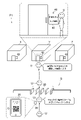
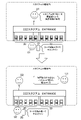
- User U can also unlock the doors of other rooms X and Z by facial recognition. However, if there are other users U whose faces are similar to each other, face authentication may not be able to distinguish them from each other. A certain user U may be authenticated as another user U. Therefore, in the first embodiment, when a plurality of users U with similar faces check in at the first location P1 and pass through the security gate G, not only face authentication but also passcode authentication are performed. It's becoming Hereinafter, a first user U1 and a second user U2 will be described as an example of a plurality of users U whose faces resemble each other, but three or more users U may have faces similar to each other.
- FIG. 3 shows the case where the first user U1 enters the room Y.
- the server 10 uses the authentication terminal 40 placed at the entrance of the room Y to perform face authentication and passcode authentication of the first user U1. Face authentication is performed in a flow similar to that described with reference to FIG.
- Passcode authentication is executed by having the first user U1 enter a passcode from the operation unit 34 of the authentication terminal 40 arranged at the entrance of the room Y.
- the authentication terminal 40 unlocks the door of the room Y when receiving from the server 10 the execution result indicating that the face authentication and the passcode authentication are successful.
- the authentication terminal 40 does not unlock the door of the room Y when receiving an execution result indicating that at least one of face authentication and passcode authentication has failed.
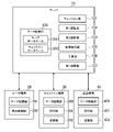
- the server 10 implements a data storage unit 100 , a check-in unit 101 , a first authentication unit 102 , a second authentication unit 103 , a second user determination unit 104 and a process execution unit 105 .
- the data storage unit 100 is realized mainly by the storage unit 12 .
- Other functions are realized mainly by the control unit 11 .
- the data storage unit 100 stores data necessary for processing in the authentication system S.
- FIG. the data storage unit 100 stores a user database DB1 and a check-in database DB2.
- FIG. 5 is a diagram showing an example of data storage in the user database DB1.
- the user database DB1 is a database that stores information about users U who have registered to use the check-in service.
- the user database DB1 stores the user ID, password, code ID, expiration date of the code ID, name, face photograph, face feature amount, passcode, and other user U with a similar face.
- a user ID is stored.
- a record corresponding to this user U is created in the user database DB1, and information such as the user ID of this user U is stored.
- a user ID is information that can identify a user U.
- the user U may be identified by information referred to by other names instead of the user ID.
- user U may be identified by a user account or other information such as an email address.
- the password is authentication information for logging into the check-in service.
- the user U can log in to the check-in service from the user terminal 20 and update his/her face photo and passcode.
- a code ID is issued at an arbitrary timing and stored in the user database DB1.
- a known rule can be applied to the code ID issuance rule itself.
- the server 10 issues the code ID so as not to duplicate the code ID of another user U within the expiration date.
- the code ID is updated when an application for displaying the code C is activated on the user terminal 20, when a certain period of time has passed since the code C was displayed, or when the user U performs a predetermined operation. be.
- the validity period of the code ID is set to the time after a predetermined time (for example, about 5 to 30 minutes) after the code ID is generated. The code ID does not have to have an expiration date.
- a facial photograph is an image of the user U's face.
- the user U takes an image of his or her own face with the imaging unit 26 of the user terminal 20 and uploads the photograph of the face to the server 10 .
- the facial photograph may be pre-stored in the user terminal 20 or another computer.
- the facial feature amount is information obtained by digitizing facial features.
- the face feature amount indicates features such as the relative position, size, or shape of facial parts.
- the feature amount of the face indicated by the photograph of the face is calculated in advance, but the feature amount of the face may be calculated on the spot at the time of authentication.
- the feature amount of the face registered in the user database DB1 is authentication information that is correct in face authentication.
- the passcode registered in the user database DB1 is the correct information for passcode authentication.
- the number of digits of the passcode may be the same for all users U, or may be arbitrarily specified by the user U. For example, the passcode may be about 2 to 8 digits.
- the passcode may be specified by the user U, or may be automatically generated by the authentication system S. It is assumed that passcodes are restricted so that users U with similar faces do not have the same passcode. For example, when a certain user A designates a passcode at the time of use registration or at any time thereafter, the server 10 refers to the user database DB1 and registers the same passcode for a user B who looks similar to the user A. determine whether or not
- the server Register the passcode in the user database DB1.
- the server 10 does not register the passcode specified by the user A in the user database DB1 when the passcode specified by the user A and the registered passcode of the user B match. In this case, the server 10 prompts the user A to specify another passcode.
- the user IDs of other users U with similar faces are also stored in each user U record.
- the server 10 based on the facial feature amount of each user U and the facial feature amounts of other users U, at an arbitrary timing such as when the user U is registered for use or when the face photo is updated. identify a combination of users U similar to each other. Based on this identification result, the server 10 stores the user IDs of other users U with similar faces in the user database DB1.
- the user U with the user ID "taro.yamada123” and the user U with the user ID “yoshida111jiro” have similar faces. Therefore, the record with the user ID “taro.yamada123” stores “yoshida111jiro” as the user ID of another user U with a similar face. The record with the user ID “yoshida111jiro” stores "taro.yamada123” as the user ID of another user U with a similar face. The user U with the user ID “hanako999” does not have another user U whose face is similar.
- the check-in section 101 allows each of the users U to check-in at the first location P1.
- the check-in unit 101 allows the first user U1 to check in to the first place P1 when the first user U1 is at or comes to the first place P1.
- the check-in unit 101 allows the second user U2 to check in to the first place P1 when the second user U2 is at or comes to the first place P1.
- Being at the first place P1 means that a certain amount of time has passed since coming to the first place P1.
- Being at the first place P1 and staying at the first place P1 have the same meaning.
- Arriving at the first place P1 means moving from another place to the first place P1. Coming to the first place P1 and visiting the first place P1 have the same meaning.
- Check-in means detecting that the user U is at or has arrived at the first place P1. Identifying the user U who is at or has come to the first place P1 corresponds to check-in. Identifying the first place P1 where the user U is or came corresponds to check-in. For example, storing information about the user U who is at or has come to the first place P1 in the check-in database DB2 corresponds to check-in. For example, sending information about the user U to the check-in terminal 30 or the authentication terminal 40 at the first place P1 where the user U came from corresponds to check-in.
- the check-in terminal 30 transmits its own terminal ID and the code ID included in the code C to the server 10.
- the check-in section 101 allows the user U identified by this code ID to check in at the first place P1.
- the check-in unit 101 refers to the user database DB1, acquires a combination of the user ID associated with the code ID, the face feature amount, and the passcode, and stores the combination in the check-in database DB2, thereby allowing the user Have U checked into the first location P1.
- the check-in unit 101 sets the passcode authentication flag to "1" if another user U with a similar face has already checked in.
- the check-in unit 101 sets the passcode authentication flag to "0" if there is no other user U with a similar face or if no other user U with a similar face has checked in.
- checkout may be performed in a similar flow.
- the check-in terminal 30 transmits its own terminal ID and the code ID included in the code C to the server 10 .
- the check-in unit 101 checks out the user U identified by this code ID from the office building.
- the check-in unit 101 refers to the user database DB1 and acquires the user ID associated with this code ID.
- the check-in section 101 causes the user U to check out from the first location P1 by deleting the record storing the acquired user ID from the check-in database DB2.
- the check-in unit 101 sets the passcode authentication flag of another user U whose face resembles that of the user U to "0". However, if there is another user U whose face is similar to that of the other user U and they are checking in, the passcode authentication flag does not become "0".
- the first authentication unit 102 can perform face authentication for the first user U1 when the first user U1 is at or comes to the first place P1. Face authentication for the first user U1 is face authentication for identity verification of the first user U1. In the first embodiment, check-in to the first location P1 occurs, so being checked in to the first location P1 corresponds to being at the first location P1. Checking in at the first place P1 corresponds to coming to the first place P1.
- the first authentication may be knowledge authentication such as passcode authentication or password authentication.
- the first authentication may be possession authentication using user U's property such as the user terminal 20 or an IC card.
- the first authentication unit 102 does not always have to perform face authentication when the first user U1 is at or comes to the first place P1, but performs face authentication at arbitrary timing. Therefore, the first authentication unit 102 only needs to be in a state in which face authentication can be performed when the first user U1 is at or comes to the first place P1.
- the first authentication unit 102 performs face authentication of the first user U1 based on the facial feature amount acquired using the authentication terminal 40 and the facial feature amount registered in the server 10 in advance. . If the difference between these face feature amounts is less than a threshold, face authentication is successful. If the difference between these face feature amounts is greater than or equal to the threshold, face authentication fails.
- the first authentication unit 102 refers to the check-in database DB2 and determines whether or not there is a record in which a facial feature amount that differs from the calculated facial feature amount by less than a threshold value is stored. If this record exists, face recognition will succeed. If this record does not exist, face authentication will fail. Face authentication may be performed using the user database DB1, but since there are records of users U who have not checked in in the user database DB1, it is possible to perform face authentication by using the check-in database DB2. It is possible to reduce the amount of facial features to be compared.
- the second authentication unit 103 can perform passcode authentication for the first user U1 when the first user U1 is at or comes to the first place P1. In the first embodiment, check-in to the first location P1 is performed, so the second authentication unit 103 performs passcode authentication when the first user U1 is at the checked-in first location P1. It is possible.
- Passcode authentication is an example of second authentication. Therefore, the description of the passcode authentication can be read as the second authentication. Any authentication method can be used for the second authentication itself.
- the second authentication may utilize other knowledge authentication such as password authentication, password authentication, or authentication to enter personal information such as a phone number.
- the second authentication may be biometric authentication or possession authentication.
- the second authentication may be any type of authentication different from the first authentication.
- the second authentication is an authentication method with a higher authentication rate than the first authentication, but the first authentication may have a higher authentication rate than the second authentication.
- the authentication rate here means the probability that false authentication does not occur.
- authentication such as passcode authentication
- success or failure is determined based on matching of authentication information corresponds to the second authentication.
- the authentication for which the success or failure is determined by the second authentication may correspond to the second authentication.
- the authentication rate is higher than face authentication, which is the first authentication.
- the second authentication may require more time and effort than the first authentication.
- the second authentication unit 103 does not always have to perform passcode authentication when the first user U1 is at or comes to the first place P1, but performs passcode authentication at any timing. Therefore, the second authentication unit 103 only needs to be in a state in which passcode authentication can be executed when the first user U1 is at or comes to the first place P1.
- the second authentication unit 103 performs passcode authentication based on the passcode acquired using the authentication terminal 40 and the passcode registered in the server 10 in advance. If they match, the passcode authentication will succeed. If they do not match, passcode authentication will fail.
- the passcode authentication not only the passcode but also the user ID may be used, but in the first embodiment, only the passcode is used without using the user ID.
- passcode authentication is performed after face authentication
- face authentication may be performed before passcode authentication.
- Both face authentication and passcode authentication may be performed in parallel instead of performing either one of face authentication and passcode authentication first.
- passcode authentication corresponds to additional authentication of face authentication.
- the second authenticating unit 103 refers to the check-in database DB2, and refers to the passcode authentication flag of the record storing the face feature amount for which the face authentication was determined to be successful. The second authentication 103 does not perform passcode authentication if the passcode authentication flag is "0", and performs passcode authentication if the passcode authentication flag is "1".
- the second authentication unit 103 requests the authentication terminal 40 for passcode authentication.
- the authentication terminal 40 transmits the passcode entered by the user U to the server 10 .
- the second authentication unit 103 performs passcode authentication based on the passcode acquired from the authentication terminal 40 and the passcode of the record storing the facial feature amount determined to be successful in face authentication. do. If they match, the passcode authentication will succeed. If they do not match, passcode authentication will fail.
- Passcode authentication may be executed using the user database DB1, but the user database DB1 also contains records of users U who have not checked in. It is possible to reduce the number of passcodes to be compared during authentication.
- the second user determination unit 104 determines whether or not the second user U2, who may be authenticated as the first user U1 by face authentication, is at or has come to the first place P1.
- face authentication is used, so that the face resembles that of the first user U1 corresponds to the possibility of being authenticated as the first user U1 by face authentication.
- biometric authentication other than face authentication
- biometric authentication if the biometric information used in biometric authentication is similar to or matches the first user U1, there is a possibility that the first user U1 will be authenticated by biometric authentication. corresponds to The similarity here also means that the difference in biometric information is less than a threshold, as in face recognition. A match here means that the biometric information is the same, although it is unlikely.
- Biometric information can be of a type that corresponds to biometric authentication. For example, in the case of fingerprint authentication, the fingerprint pattern corresponds to biometric information. In iris authentication, the iris pattern corresponds to biometric information.
- the second user determination unit 104 determines whether the second user U2 is at or has come to the first place P1.
- the second user determination unit 104 determines whether the second user U2 is at or has come to the first place P1 by determining whether the second user U2 has checked in at the first place P1.
- the second user determination unit 104 determines that the second user U2 is at the first place P1 when there is a record corresponding to the second user U2 in the check-in database DB2.
- the second user determination unit 104 determines that the second user U2 has come to the first place P1 when a record corresponding to the second user U2 is added to the check-in database DB2.
- the process execution unit 105 determines that the second user U2 is not at or has come to the first place P1. Execute the unlocking process based on the authentication. The process executing unit 105 executes unlocking process based on face authentication when the first user U1 is at the checked-in first place P1. When it is determined that the second user U2 is at or has come to the first place P1, the unlocking process may be executed under conditions other than successful face authentication.
- the user terminal 20 implements a data storage unit 200 and a display control unit 201 .
- the data storage unit 200 is implemented mainly by the storage unit 22 .
- the display control unit 201 is realized mainly by the control unit 21 .
- the check-in terminal 30 implements a data storage unit 300 , a reception unit 301 and a transmission unit 302 .
- Data storage unit 300 is realized mainly by storage unit 32 .
- Other functions are realized mainly by the control unit 31 .
- the data storage unit 300 stores data necessary for check-in.
- the data storage unit 300 stores a terminal ID with which the check-in terminal 30 can be identified and information with which the server 10 can be identified.
- the data storage unit 300 may store information that enables identification of the place where the check-in terminal 30 is arranged.
- the receiving unit 301 receives any operation.
- the details of the operation accepted by the accepting unit 301 are transmitted to the server 10 by the transmitting unit 302 .
- the transmission unit 302 transmits information necessary for check-in to the server 10 .
- the transmission unit 302 transmits the code ID acquired by the check-in terminal 30.
- the code ID is recorded in the data storage unit 200 of the user terminal 20, so the transmitting unit 302 acquires the code ID recorded in the user terminal 20.
- the transmission unit 302 acquires the code ID when the code C is read by the check-in terminal 30 .
- the check-in terminal 30 may be a terminal for acquiring the code ID, and may be any terminal that corresponds to the method of acquiring the code ID.
- the authentication terminal 40 implements a data storage unit 400 , a reception unit 401 and a transmission unit 402 .
- Data storage unit 400 is realized mainly by storage unit 42 .
- Other functions are realized mainly by the control unit 41 .
- the data storage unit 400 stores data required for authentication.
- the data storage unit 400 stores a terminal ID with which the authentication terminal 40 can be identified and information with which the server 10 can be identified.
- the data storage unit 400 may store information that enables identification of the location where the authentication terminal 40 is arranged.
- the accepting unit 401 accepts input of a passcode.
- the accepting unit 401 can accept other arbitrary operations.
- the content of the operation accepted by the accepting unit 401 is transmitted to the server 10 by the transmitting unit 402 .
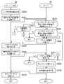
- FIG. 7 is a flow chart showing an example of processing executed in the authentication system S of the first embodiment.
- the processing shown in FIG. 7 is executed by each of control units 11 , 21 , 31 and 41 operating according to a program stored in each of storage units 12 , 22 , 32 and 42 .
- the processing in FIG. 7 is an example of processing executed by the functional blocks in FIG. It is assumed that the user U has already registered for use before the process of FIG. 7 is executed.
- the first user U1 and the second user U2 are simply referred to as user U without distinguishing between them.
- the code C is displayed on the display unit 25 based on the code ID stored in the storage unit 22. This processing is omitted in FIG.
- the check-in terminal 30 acquires the code ID included in the code C read by the reading unit 37 (S100). ).
- the check-in terminal 30 transmits its own terminal ID stored in the storage unit 32 and the code ID acquired in S100 to the server 10 (S101).
- the server 10 Upon receiving the terminal ID and code ID, the server 10 refers to the user database DB1 and executes check-in (S102). At S102, the server 10 confirms the code ID and expiration date. If the code ID is within the expiration date, the server 10 acquires the user ID, facial features, and passcode associated with this code ID, and stores them in the check-in database DB2 together with the check-in date and time and the passcode authentication flag. Store. The server 10 transmits the check-in execution result to the check-in terminal 30 . It should be noted that if the received code ID is not valid, the process ends without performing check-in.
- the user U will be able to enter the office building at the first location P1 and perform unlock processing by face authentication.
- the authentication terminal 40 sends the server 10 its own terminal ID, the imaging unit 46 is transmitted (S104).
- the server 10 Upon receiving the captured image, the server 10 performs face authentication based on the check-in database DB2 (S105).
- the server 10 calculates the feature amount of the face captured in the captured image.
- the server 10 refers to the check-in database DB2 and acquires the facial feature value associated with the terminal ID of the authentication terminal 40 that has transmitted the captured image.
- the server 10 performs face authentication based on the facial feature amount calculated from the captured image and the facial feature amount acquired from the check-in database DB2.
- the server 10 determines that face authentication has succeeded if even one of these differences is less than the threshold. When users U whose faces are similar to each other are checking in, face authentication will succeed with a plurality of face feature amounts.
- the server 10 Upon receiving the passcode and terminal ID, the server 10 executes passcode authentication (S109).
- the server 10 refers to the check-in database DB2 and acquires the passcode stored in the record for which the face authentication was successful in S105.
- the server 10 determines whether the obtained passcode matches the passcode received from the authentication terminal 40 . If they match, passcode authentication succeeds.
- the server 10 transmits a success notification indicating that the authentication has succeeded to the authentication terminal 40 (S110).
- the authentication terminal 40 executes unlocking processing for unlocking the door (S111), and ends this processing.
- output of a signal for unlocking the electronic lock and the like are executed.
- the user U can enter the room because the face authentication and the passcode authentication are successful.
- a predetermined error message is displayed on the display unit 45 of the authentication terminal 40, and this process ends.
- S105 if the face authentication is successful with only one facial feature amount (S105; 1), that is, the second user U2 has not checked in to the office building and the facial feature amount has been successfully authenticated. is stored, the passcode authentication flag is "0", the process proceeds to S110 without requesting passcode authentication. In this case, the user U can enter the room only by facial recognition.
- S105 if the face authentication is not successful (S105; failure), a predetermined error message is displayed on the display unit 45 of the authentication terminal 40, and this process ends.
- the authentication system S of the first embodiment when it is not determined that the second user U2, who may be authenticated as the first user U1 by face authentication, is at or has come to the first place P1, based on face authentication to execute the unlock process.
- This prevents the first user U1 and the second user U2 from being indistinguishable from each other, and ensures the execution of identity verification, thereby enhancing security.
- the first user U1 can enter the room only by face recognition when it is not determined that the second user U2 is at or has come to the first place P1, so the convenience of the first user U1 is enhanced. Also, in this case, since there is no need to perform passcode authentication, the processing load on the authentication system S can be reduced.
- the authentication system S performs face authentication. Execute the unlocking process based on Since the second user U has left the first place P1, the first user U1 and the second user U2 cannot be distinguished from each other even if only face authentication is used. Therefore, the personal identification is surely executed, and the security is enhanced. Since the first user U1 can enter the room only by facial recognition, convenience for the first user U1 is enhanced. Also, in this case, since there is no need to perform passcode authentication, the processing load on the authentication system S can be reduced.
- the authentication system S executes unlock processing based on face authentication when the first user U1 is at the checked-in first place P1. This prevents spoofing at the first location P1 where the first user U1 has checked in, and ensures the identity verification at the first location P1, thereby enhancing security.
- the authentication system S determines whether the second user U2 is at or has arrived at the first place P1 by determining whether the second user U2 has checked in at the first place P1. This makes it possible to reliably determine whether or not the second user U2 is at or has come to the first place P1. In addition, spoofing at the first location P1 where the second user U2 has checked in is prevented, and identity verification is reliably performed at the first location P1, thereby enhancing security.
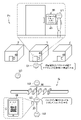
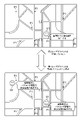
- FIG.8 and FIG.9 is a figure which shows an example of the authentication system S of 2nd Embodiment.
- This company resides in each of a first office building located at a first location P1 and a second office building located at a second location P2.
- a security gate G similar to that of the first embodiment is arranged at each of the first location P1 and the second location P2.
- the first user U1 can check-in at any one of the first location P1 and the second location P2. For example, a first user U1 can move to a second location P2 after checking in at a first location P1.
- a second user U2 can also check-in at any of the first location P1 and the second location P2.
- the second user U2 can move to the first location P1 after checking in at the second location P2.
- the authentication at the time of check-in may be the same as in the first embodiment, but in the second embodiment, the case where face authentication is used as the authentication at the time of check-in will be taken as an example. That is, the case where face authentication is performed at the time of check-in at each of the first place P1 and the second place P2 will be taken as an example. However, since the faces of the first user U1 and the second user U2 are similar to each other, not only the face authentication but also the passcode authentication are performed at check-in in principle.
- the second user U2 tries to check in at the second place P2. and In this case, the authentication system S cannot determine whether the person checking in at the second place P2 is the first user U1 or the second user U2 by face authentication alone. Authentication is also required.
- the second user U2 performs face authentication and passcode authentication from the check-in terminal 30 at the second location P2. If the face authentication and passcode authentication of the second user U2 are successful, the second user U2 checks in at the second location P2. A second user U2 passes through a security gate G at a second location P2. The flow when entering a room in the office building at the second location P2 may be the same as in the first embodiment, but this flow is omitted in the second embodiment.
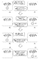
- the authentication system S can recognize that the second user U2 is at the second location P2. Since there is a certain amount of distance between the first place P1 and the second place P2, when the second user U2 checks in at the second place P2, the second user will wait until a certain amount of time has passed. Cannot move to 1 place P1. Therefore, in the second embodiment, the first user U1 is allowed to check in to the first place P1 only by facial recognition within a period during which it is expected that the second user U2 cannot move to the first place P1. there is Henceforth, this period is described as a prediction period.
- the travel time required to move between the first location P1 and the second location P2 is one hour.
- the second user U2 checks in at the second location P2 at 11:30
- the second user U2 checks in at the first location P1 from 11:30 to 12:30 one hour later. predicted to be unable to move to Therefore, the first user U1 can check-in at the first location P1 only by facial recognition until 12:30.
- the first user U1 checks in at the first location P1 at 12:00 only by facial recognition
- the first user U1 is at the second location P2 from 12:00 to 13:00, one hour later. Predicted to be immobile. Therefore, even if the second user U2 temporarily leaves the second place P2 for lunch, for example, the second user U2 can check in at the second place P2 only by facial recognition until 13:00.
- checkout from each of the first location P1 and the second location P2 may be performed, checkout is not performed in the second embodiment. Therefore, even if the second user U2 leaves the second place P2, the authentication system S cannot recognize that the second user U2 has left the second place P2. Similarly, even if the first user U1 leaves the first place P1, the authentication system S cannot grasp that the first user U1 has left the first place P1.
- the second user U2 after temporarily leaving the second location P2, the second user U2 tries to check in at the second location P2 at 12:50.
- the second user U2 can check-in at the second place P2 only by facial recognition because it is within the predicted period during which it is predicted that the first user U1 cannot move to the second place P2.
- the second user U2 will leave the second place P2 and come to the first place P1. become unable.
- the first user U1 tries to re-enter the first place P1 at 14:10.
- the first user U1 needs to successfully perform face authentication and passcode authentication in order to check in at the first location P1.
- the second user U2 is the first user only with face authentication from 14:10 to 15:10 one hour later. It becomes possible to check in at two locations P2.
- FIG. 10 is a functional block diagram showing an example of functions realized by the authentication system S of the second embodiment.
- the server 10 implements a data storage unit 100, a check-in unit 101, a first authentication unit 102, a second authentication unit 103, a process execution unit 105, a prediction unit 106, and a first restriction unit 107. be done.
- Each of the prediction unit 106 and the first restriction unit 107 is implemented mainly by the control unit 11 .
- the data storage unit 100 stores substantially the same data as in the first embodiment, but the contents of the check-in database DB2 are different from those in the first embodiment.
- the data storage unit 100 may store a database regarding the first location P1 and the second location P2. It is assumed that this database stores first location information about the first location P1 and second location information about the second location P2. These positions can be specified by arbitrary information, for example, latitude and longitude information, addresses, postal codes, coordinate information, or combinations thereof.
- the first location information is latitude and longitude information of the first location P1 and the second location information is latitude and longitude information of the second location P2.
- FIG. 11 is a diagram showing a data storage example of the check-in database DB2 of the second embodiment.
- the check-in to the first place P1 and the check-in to the second place P2 are managed by one check-in database DB2, but they are separate check-in databases. It may be managed by DB2.
- the check-in database DB2 stores only the place IDs of the first place P1 and the second place P2, the user ID of the user U who has already checked in, the check-in date and time, the prediction period, and the face authentication. The feature amount of the face of the user U who is permitted to check in at is stored.
- the first user U1 indicated by the user ID "taro.yamada123” has checked in at the location ID "p00001" of the first location P1.
- "June 10, 2021, 13:00:41” is set as a predicted period during which the first user U1 can check in only by face authentication. This prediction period is one hour after the latest check-in date and time "June 10, 2021, 12:00:41” when the second user U2 checked in at the second place P2.
- "Feature amount 1" shown in FIG. 11 is the feature amount of the face of the first user U1.
- this "feature amount 1" is the correct face feature amount in face authentication.
- the second user U2 indicated by the user ID "yoshida111jiro” has checked in at the location ID "p00002" of the second location P2.
- "June 10, 2021, 12:30:25” is set as a predicted period during which the second user U2 can check in only by face authentication. This prediction period is one hour after the check-in date and time "11:30:25 on June 10, 2021" when the first user U1 most recently checked in at the first place P1.
- "Feature amount 2" shown in FIG. 11 is the feature amount of the face of the second user U2.
- this "feature amount 2" is the correct face feature amount in face authentication.
- the check-in unit 101 checks the first user U1 at the first place. Let P1 check in. Also, the check-in section 101 checks in the second user U2 to the second place P2.
- the process execution unit 105 executes check-in. In the second embodiment, check-in outside the prediction period will be described as processing of the check-in unit 101 , and check-in within the prediction period will be described as processing of the processing execution unit 105 .
- the check-in unit 101 stores the user ID and Stores check-in date and time. Also, the check-in unit 101 stores the prediction period predicted by the prediction unit 106 and the facial feature amount of the first user U1 stored in the user database DB1. The check-in unit 101 may identify the first user U1 whose face is similar to the second user U2 who has checked in at the second place P2 from among all the users U stored in the user database DB1. As described in the first embodiment, it may be stored in advance in the user database DB1 that the second user U2 and the first user U1 have similar faces.
- the prediction unit 106 generates second time information about a second time when the second user U2, who is likely to be authenticated as the first user U1 by face authentication, was at or came to the second place P2, and the second time information about the second place P2.
- a prediction period during which the second user U2 will not or will not be at the first location P1 is predicted based on at least one of the two location information. In the second embodiment, the prediction period is predicted based on both the second time information and the second location information. may be predicted.
- the date and time of check-in at the second location P2 corresponds to the second time.
- the time may mean only the time instead of the date and time, or may mean only the date. Time may also mean a period of time having a certain length.
- the part describing the check-in time to the second location P2 can be read as the second time. If check-in to the second place P2 does not occur, the time when it is detected that the second user U2 was or came to the second place P2 may correspond to the second time. This detection method will be described later in a modified example.
- the prediction unit 106 acquires the distance between the first location P1 and the second location P2 based on the first location information and the second location information regarding the first location P1, and calculates the second time information. and the travel time according to the distance.
- This travel time may be calculated using a known navigation algorithm. For example, a standard moving speed is defined for each mode of transportation such as walking, car, bicycle, train, or bus.
- the prediction unit 106 calculates the travel time based on this travel speed and the distance between the first location P1 and the second location P2.
- the prediction unit 106 predicts the period from the second time indicated by the second time information to the time after the travel time as the prediction period.
- the prediction period may be predicted based on at least one of the second time information and the second location information.
- the prediction unit 106 may predict, as a prediction period, a period from the second time indicated by the second time information to a predetermined time later. In this case, the prediction period is obtained without using the second location information.
- the prediction unit 106 may predict the period associated with the second location information as the prediction period. In this case, the prediction period is obtained without using the second time information.
- the prediction unit 106 when at least one of the second time information and the second location information is updated, the prediction unit 106, based on at least one of the updated second time information and the second location information, Update the forecast period. The only difference is that updated information is used, and the prediction method itself for the prediction period is as described above. In the second embodiment, since check-in to the second place P2 occurs, the prediction unit 106 predicts the prediction period when the second user U2 checks in to the second place P2.
- the first restriction unit 107 restricts execution of check-in based on face authentication when the prediction period has passed.
- check-in to the first location P1 corresponds to the first process. Therefore, the description of check-in to the first location P1 in the second embodiment can be read as the first process.
- the first process of the first embodiment differs from the first process of the second embodiment, the unlocking process described in the first embodiment corresponds to the first process in the second embodiment as well. may As described in the first embodiment, the first process may be any process.
- the first restriction unit 107 requests passcode authentication so that check-in is performed based on face authentication and passcode authentication, so that check-in is performed based on face authentication.
- the limiting method by the first limiting unit 107 is not limited to the example of the second embodiment.
- the first restriction unit 107 may restrict execution of check-in based on face authentication by requesting other authentication without performing face authentication.
- Other authentication may be authentication using the user terminal 20 as described in the first embodiment, or authentication with a higher recognition rate such as fingerprint authentication or iris authentication.
- the first restriction unit 107 may restrict execution of check-in based on face authentication by requesting the manager of the office building to check-in face-to-face.
- the process executing unit 105 executes check-in to the first location P1 based on the face authentication executed during the prediction period.
- the process executing unit 105 executes check-in to the first location P1 when the face authentication executed during the prediction period is successful.
- the process execution unit 105 does not perform check-in to the first place P1 based only on face authentication when the prediction period has passed.
- the check-in in this case is executed by the check-in unit 101, and the check-in requires passcode authentication.
- the check-in processing itself of the processing execution unit 105 is the same as the processing of the check-in unit 101 .
- FIG. 12 is a flowchart showing an example of processing executed by the authentication system S of the second embodiment.
- the processing shown in FIG. 12 is executed by each of control units 11, 21, 31 and 41 operating according to a program stored in storage units 12, 22, 32 and 42, respectively.
- the processing in FIG. 12 is an example of processing executed by the functional blocks in FIG. It is assumed that the user U has already registered for use before the process of FIG. 12 is executed.
- the first user U1 can also check in at the second location P2 without checking in at the first location P1.
- the second user U2 may check in at the first location P1 without checking in at the second location P2. Therefore, in FIG. 12, the first user U1 and the second user U2 are simply referred to as user U without distinction.
- This user U is a person who is going to check in at either the first location P1 or the second location P2.
- the first location P1 and the second location P2 are simply referred to as location P without distinguishing between them.
- This place P is the place where the user U is going to check-in.
- the check-in terminal 30 at this place P takes an image of the user U's face using the imaging unit 36 (S200).
- the check-in terminal 30 transmits to the server 10 its own terminal ID and a photographed image of the face of the user U (S201).
- the server 10 receives the captured image and the terminal ID, the server 10 acquires the feature amount of the face captured in the captured image. It is determined whether or not a facial feature amount similar to the facial feature amount acquired from the captured image is stored (S202).
- the server 10 determines whether facial feature amounts similar to the facial feature amounts acquired in S202 are stored in the user database DB1. It is determined whether or not (S203). If it is not determined that a facial feature amount similar to the facial feature amount acquired in S202 is stored (S203; N), a predetermined error message is displayed on the display unit 35 of the check-in terminal 30, and this process ends. finish.
- the server 10 If it is determined in S203 that a plurality of facial feature quantities similar to the facial feature quantity acquired in S202 are stored (S203; plural), the server 10 prompts the check-in terminal 30 for passcode authentication. request (S204). When the passcode authentication is requested, the check-in terminal 30 causes the display unit 45 to display a screen prompting for the passcode input, and accepts the passcode input (S205). The check-in terminal 30 transmits the passcode input from the operation unit 34 and its own terminal ID to the server 10 (S206).
- At least one of the second time information about the second time when the second user U2 was or came to the second place P2 and the second place information about the second place P2. predicts a predicted period during which the second user U2 will not or will not be at the first location P1 based on and performs check-in at the first location P1 based on the first authentication performed during the predicted period.
- the first authentication unit 102 and the second authentication unit 103 are generally similar to those of the first and second embodiments. However, in the second embodiment, the first authentication unit 102 performs face authentication for each of the multiple users U based on the authentication information of each of the multiple users U extracted from the user database DB1.
- the first authentication unit 102 may refer to the user database when performing face authentication. Run. Since the schedule information database DB3 stores only the feature amount of the face of the user U who is scheduled to be or will be on the scheduled date or time of the seminar, the feature amount of the face to be compared at the time of face authentication is reduced. can be done.
- face authentication is an example of first authentication.
- Passcode authentication is an example of second authentication. Any combination of the first authentication and the second authentication may be used.
- the first authentication may be face authentication, and the second authentication may be fingerprint authentication or iris authentication.
- the first authentication may be face authentication, and the second authentication may be authentication using the code C of the user terminal 20 as described in the first embodiment.
- modification 1-2 when it is determined that the second user U2 is at or has arrived at the first location P1, the payment process is executed based on passcode authentication, not based on face authentication.
- passcode authentication not based on face authentication.
- the first user U1 checks only by facial recognition at the check-in terminal 30 at the entrance of the stadium.
- the check-in can be done only by facial recognition.
- the server 10 confirms that the first user U1 is at the store. can be detected.
- the first user U1 may be able to use the electronic payment service with facial recognition at each store where the event is held.
- the processing execution unit 105 of modification 1-4 executes payment processing based on code authentication.
- the processing execution unit 105 executes settlement processing when the code authentication is successful.
- the process executing unit 105 does not execute the payment process when the code authentication fails.
- the first authentication unit 102 can perform face authentication after the payment processing based on code authentication is performed.
- the second user determination unit 104 determines whether or not the second user U2 is at or has come to the first place P1 after the settlement process based on code authentication is executed.
- the user terminal 20 may acquire first location information regarding a first location of the first user U1.
- the first location is the current location of the first user U1.
- the method itself for acquiring the first position information may be any method.
- a method using GNSS such as the GPS receiver 28, a method using a wireless LAN access point, or a method using a communication base station can be used.
- the first location information like the first location information, may be in any format.
- the first location information may be latitude/longitude information, address information, or coordinate information.
- the processing execution unit 105 executes payment processing based on face authentication when the first location indicated by the first location information is the first location P1 or its vicinity.
- the settlement process is not executed only by face recognition. Therefore, even if someone whose face resembles that of the first user U1 or the second user U2 attempts payment processing by face authentication at another first location P1, the payment processing by face authentication is not permitted, so the payment cannot be made. Processing fails.
- the settlement process based on face authentication succeeds only at the first location indicated by the first location information or at the first location P1 in the vicinity thereof.
- the first location indicated by the first location information is the first location P1 or its vicinity
- payment processing is executed based on face recognition.
- face authentication only at the first place P1 where the first user U1 is certainly present, preventing spoofing at other first places P1 and enhancing security.
- the first user U1 can execute payment processing by face authentication at the first location P1 where he/she is, which increases convenience.
- the second user determination unit 104 may determine whether or not the second user U2 is at or has come to the first place P1 by determining whether or not payment processing has been executed. For example, in the example of FIG. 18, even if the second user U2 enters the stadium with a paper ticket, when the second user U2 executes the payment processing by code authentication in the stadium, the server 10 It can be detected that the second user U2 is in the stadium.
- the server 10 when the second user U2 executes payment processing by code authentication at one of the plurality of first locations P1, the server 10 sends the second user U2 to the first location P1. It can detect the presence of U2.
- the settlement process may be executed by any method other than code authentication.
- the settlement process may be executed by the IC chip 27 of the user terminal 20 or the IC card owned by the second user U2.
- the second user determination unit 104 determines whether or not the second position indicated by the second position information regarding the second position of the second user U2 is at or near the first place P1. It may be determined whether the user U2 is at or has come to the first location P1. As in the case of the first position information, any method may be used to acquire the second position information.
- the second location is the current location of the second user U2. As shown in FIG. 20, if the location information of the second user U2 can be acquired using the user terminal 20, it can be determined whether or not the second user U2 is at or near the first location P1. It is possible to prevent indistinguishability from two users U2.
- the second user U2 by determining whether the second position indicated by the second position information regarding the second position of the second user U2 is at or near the first place P1, the second user U2 Determine whether U2 is or has arrived at the first location P1. As a result, it is possible to reliably detect that the second user U2 is at or has come to the first place P1, and the identification of the first user U1 is reliably performed, thereby enhancing security.
- the authentication system S A prediction unit 106 may also be included that predicts a prediction period during which the two users U2 will not or will not be at the first location P1.
- the prediction unit 106 is the same as in the second embodiment.
- the processing execution unit 105 executes payment processing based on the first authentication executed during the prediction period. For example, in the example of FIG. 19, when the second user U2 checks in at a certain first place P1 or executes payment processing at a certain first place P1, a prediction period is set for each first place P1. be done. During this prediction period, the first user U1 will be able to perform payment processing only by face recognition.
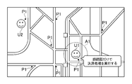
- FIG. 22 is a diagram showing an example of an authentication system S of modification 2-1. As shown in FIG. 22, when the authentication system S is applied to the electronic payment service, the payment process using the payment information of the first user U1 corresponds to the first process described in the second embodiment. The payment processing of modification 2-1 is executed when both face authentication and passcode authentication are successful, as in the check-in of the second embodiment.
- the second user U2 executes the payment process at the second place P2 at 11:30 by face authentication and passcode authentication
- the payment process is performed from 11:30 to 12:30 one hour later.
- FIG. 23 is a diagram showing an example of an authentication system S of modification 2-2.
- the prediction unit 106 predicts based on at least one of second time information corresponding to each of the plurality of second users U2 and second location information corresponding to each of the plurality of second users U2. You can predict the period.
- the prediction period is predicted based on both the second time information and the second location information will be described. Time may be predicted.
- FIG. 23 shows a case where there are two second users U2 whose faces are similar to the first user U1. It is also assumed that each of the two second users is at a separate second location P2. For example, it is assumed that the first second user U2 performed a payment process at 11:30 at the second place P2 by face authentication and passcode authentication. It is assumed that it takes one hour to move between the second place P2 and the first place P1. At this point, the location of the second user U2 is still unknown, so the first user U1 will not be able to execute payment processing only by face recognition.
- the second user U2 made a payment at another second place P2 at 11:35. It is assumed that it takes 30 minutes to move between the second place P2 and the first place P1.
- the prediction period during which the first second user U2 is not expected to come to the first place P1 is up to 12:30.
- the prediction period during which the second user U2 is predicted not to come to the first location P1 is until 12:05.
- the first user U1 can execute the payment process at the first location P1 only by face recognition until 12:05, which is the earliest prediction period.
- the prediction unit 106 predicts the prediction period for each second user U2 when there are multiple second users U2.
- the processing execution unit 105 executes payment processing based on the face recognition executed in the earliest prediction period among the prediction periods corresponding to each of the plurality of second users U2. That is, the process execution unit 105 performs the settlement process at the first place P1 by the first user U1 only by face recognition if the prediction period ends earliest among the prediction periods corresponding to each of the plurality of second users U2. allow it to run.
- modification 2-2 based on at least one of the second time information corresponding to each of the plurality of second users U2 and the second location information corresponding to each of the plurality of second users U2, Forecast the forecast period.
- This prevents the first user U1 and the second user U2 from being indistinguishable from each other even if there are a plurality of second users U2 whose faces are similar to that of the first user U1.
- Increased security Since the first user U1 can execute the settlement process only by face recognition within the prediction period, the convenience of the first user U1 is enhanced. Also, in this case, since there is no need to perform passcode authentication, the processing load on the authentication system S can be reduced.
- the first authentication unit 102 may be able to perform face authentication when the first user U1 has checked in and is at the first location P1.
- the process executing unit 105 executes the settlement process when the first user U1 has checked in to the first place P1 and is at the first place P1. Also in this case, the prediction period is predicted when the second user U2 performs check-in or payment processing at the second place P2 different from the first place P1 where the stadium is located.
- the settlement process is executed when the first user U1 has checked in to the first place P1 and is at the first place P1. Accordingly, the first place P1 where the first user U1 is located can be reliably specified by the check-in by the first user U1. Therefore, it is possible to prevent the settlement processing by face authentication from being permitted at a place where the first user U1 does not visit, and to prevent the settlement processing from being executed by someone with a similar face visiting during the prediction period. is executed reliably to increase security.
- the payment process may be executed based on the face authentication executed during the prediction period. That is, even if the first user U1 succeeds in the passcode authentication and is in a state where it is known with certainty that he/she is in the first place P1, the settlement process is executed based on the face authentication executed during the prediction period. good.
- the second authentication unit 103 can perform passcode authentication when the first user U1 is at or comes to the first place P1.
- This passcode authentication is authentication for inputting a user ID and a passcode.
- the second authentication may be authentication other than passcode authentication.
- code authentication using a code C displayed on the user terminal 20 may be used.
- the process execution unit 105 may perform check-in for the second user U2 when the second user U2 is at or comes to the second place P2.
- This check-in is a check-in to the second location P2.
- check-in corresponds to the second process.
- the second process may be any process other than check-in. The second process only needs to be able to somehow detect the presence of the second user U2, and may be a payment process.
- the prediction unit 106 may predict the prediction period when check-in for the second user is performed.
- the second time may be the time when the second location information regarding the second location of the second user U2 is acquired.
- the second location P2 corresponds to the second position.
- the user terminal 20 of the second user U2 acquires second time information when second location information is acquired.
- the second time information may be obtained using the GPS receiver 28, or may be obtained using a real-time clock or the like.
- the second location information indicates the location of the user terminal 20 of the second user U2 instead of indicating the location where the check-in terminal 30 or the authentication terminal 40 at the second location P2 is located.
- the flow of processing using the second position information and the second time information is the same as in the second embodiment.
- the second time is the time when the second location information regarding the second location of the second user U2 is acquired by the second location acquisition unit.
- 2 Location P2 is the second location.
- the authentication system S may further include a second user determination unit 104 that determines whether or not the second user U2 is at or has come to the first location P1.
- the second user determination unit 104 is as described in the first embodiment. For example, it is detected that the second user U2 is at or has arrived at the first place P1 by checking in. Alternatively, for example, it may be determined that the second user U2 is at or has come to the first place P1 when the second user U2 executes payment processing by face authentication and passcode authentication at the first place P1. .
- the processing execution unit 105 executes payment processing based on face recognition performed during the prediction period when it is not determined that the second user U2 is at or has arrived at the first location P1. For example, when it is determined that the second user U2 is at or has come to the first place P1, the processing execution unit 105 performs the payment processing based on the passcode authentication as well as the face authentication performed during the prediction period. Run. In this case, face authentication does not have to be performed, as in modification 1-2.
- the payment process is executed based on the face recognition performed during the prediction period. Since it is more certain that the second user U2 is not at the first location P1 or has not been at the first location P1 during the prediction period, the second user U2 is not at the first location P1 in this case. By executing settlement processing, personal identification is surely executed and security is enhanced.
- FIG. 24 is an example of a functional block diagram in a modification according to the third embodiment. As shown in FIG. 24, in the modification according to the third embodiment, in addition to the functions of FIG. A unit 112, a first transmitter 113, and a second transmitter 114 are implemented. Each of these functions is realized mainly by the control unit 11 .
- the passcode authentication of this modified example also uses the user ID. That is, when it is determined that the second user U2 is at or has come to the first place P1, the processing execution unit 105 performs passcode authentication using a user ID and a passcode, not based on face authentication. , perform check-in.
- This passcode authentication is as described in modification 1-1. As described in modification 1-1, any combination of the first authentication and the second authentication may be used.
- passcode authentication is performed without face authentication. Perform check-in based on As a result, even if each of the first user U1 and the second user U2 is at or is scheduled to come to the first place P1 at the same time and the first user U1 and the second user U2 cannot be distinguished from each other, the pass Security is enhanced by reliably performing identity verification through code authentication.
- the processing execution unit 105 performs Perform check-in based on facial recognition.
- passcode authentication may not be executed, or passcode authentication itself may be executed, but the execution result of passcode authentication may not be a condition for whether or not to execute check-in. .
- FIG. 26 is a diagram showing an example of an authentication system S of modification 3-3.
- the first user U1 operates the user terminal 20 to apply for a seminar reservation.
- a list of dates and times of seminars is displayed on the user terminal 20 .
- the user U can reserve a seminar by selecting an arbitrary holding date and time.
- the authentication system S designates the second scheduled date or the second scheduled date and time when the second user U2 is or will be at the first location P1 as the first scheduled date or the first scheduled date and time.
- a second restricting unit 111 may be further included.
- the second restriction unit 111 restricts the user terminal 20 from selecting this date and time.
- Methods of this limitation include not displaying the input form for selecting this date and time, invalidating this input form, or not displaying this date and time.
- the authentication system S confirms that the second scheduled date or the second scheduled date and time is designated as the first scheduled date or the first scheduled date and time.
- a permitting unit 112 for permitting may be further included.
- the first user U1 selects check-in by other authentication method such as passcode authentication or code authentication using the user terminal 20 instead of face authentication
- the seminar on the same date and time as the second user U2 can be specified.
- the first user U1 reserves a seminar on a screen such as that shown in FIG. 26, it is assumed that the authentication method for that day can be designated. It is assumed that the authentication method specified by the first user U1 is stored in the schedule information database DB3. On the day of the seminar, the first user U1 checks in using the authentication method specified by him/herself. Various known methods can be used for this authentication itself.
- the second scheduled date or the second scheduled date and time is the first scheduled date or the first scheduled date and time Allow to be specified. This prevents the first user U1 and the second user U2 from being indistinguishable from each other, and ensures the execution of identity verification, thereby enhancing security.
- the authentication system S further includes a first transmission unit 113 that transmits a notification prompting the first user U1 not to perform face authentication at the first location P1 when the first user U1 designates another authentication. It's okay.
- This notification can be sent in any way, for example by email, SNS, SMS, or a messaging app. It is assumed that the format of this notification is stored in the data storage unit 100 . This notification will not be sent if the first user U1 has booked a seminar on a date and time different from that of the second user U2. This notification includes a message indicating that face authentication will not be performed at the first location P1.
- the first user U1 uses other authentication methods such as passcode authentication or code authentication.
- modification 3-5 when the first user U1 designates another authentication, a notification is sent to the first user U1 urging not to perform the first authentication at the first location P1. This prevents the first user U1 and the second user U2 from becoming indistinguishable from each other, and ensures the execution of identity verification, thereby enhancing security.
- the second user U2 may be at or will be at the first location P1 at a second scheduled date and time on the same day as the first scheduled date and time. That is, the first user U1 and the second user U2 are scheduled to come to the first place P1 on the same day, but at slightly different times. For example, the time when the first user U1 comes to the first place P1 and the time when the second user U2 comes to the first place P2 are different by several minutes to half a day.
- the authentication system S instructs the first user U1 to perform face authentication at the first location P1 on the first scheduled date and time, and to be at the first location P1 at a different time on the same day as the first scheduled date and time.
- the second transmission unit 114 may further include a second transmission unit 114 that transmits a notification prompting the use of other authentication, if any.
- this notification can be sent in any manner. This notification will not be sent if the first user U1 has booked a seminar on a different day than the second user U2.
- This notification includes a message indicating that face authentication will be performed only at the time the user arrives at the first location P1 or within a predetermined time period from that time. Also, this notification includes a message indicating that if the user comes to the first location P1 outside of this period, authentication other than face authentication will be performed.
- the first user U1 uses other authentication methods such as passcode authentication or code authentication.
- the authentication system S determines whether the second user U2 was at the second place P2 or Prediction for predicting a prediction period during which the second user U2 will not or will not be at the first location P1 based on at least one of second time information about the second time of arrival and second location information about the second location P2.
- a portion 106 may also be included.
- the prediction unit 106 is as described in the second embodiment.
- the prediction unit 106 calculates the distance between the first location P1 and the second location P2 based on the first location information and the second location information regarding the first location P1. and predict the prediction period based on the second time information and the travel time according to the distance.
- the prediction method of the prediction period as described in the second embodiment can be used.
- the processing execution unit 105 When it is determined that the second user U2 is at or will come to the first place P1 on the first scheduled date or the first scheduled date and time, the processing execution unit 105 performs a check based on face authentication performed during the prediction period. run in. In the second embodiment, whether or not the second user U2 is present or will come to the first location P1 on the first scheduled date or the first scheduled date and time is a condition for whether or not to perform check-in. different from Other points of the processing execution unit 105 are as described in the second embodiment.
- the modification 3-7 when it is determined that the second user U2 is at or will come to the first place P1 on the first scheduled date or the first scheduled date and time, based on the face authentication performed during the prediction period to execute the first process.
- This prevents the first user U1 and the second user U2 from being indistinguishable from each other, and ensures the execution of identity verification, thereby enhancing security.
- it is possible to prevent the second user U2 from impersonating the first user U1 and checking in. Since the first user U1 can check in only by facial recognition within the prediction period, the convenience of the first user U1 is enhanced. Also, in this case, since there is no need to perform passcode authentication, the processing load on the authentication system S can be reduced.
- the authentication system S acquires the distance between the first location P1 and the second location P2 based on the first location information and the second location information regarding the first location P1, and obtains the second time information, By predicting the prediction period based on the travel time according to the distance, the prediction period can be accurately predicted. By predicting an accurate prediction period, it is possible to more reliably prevent the first user U1 and the second user U2 from being indistinguishable from each other, and to ensure identity verification to increase security.
- the second location information is location information acquired using an application different from the application for accepting reservations for the first location P1. Acquiring information accurately increases security.
- what is used as the second authentication may be to enter personal information such as a phone number or email address.
- the personal information is assumed to be stored in the user database DB1.
- the server 10 Based on the user database DB1, the server 10 identifies a portion of personal information that differs between the first user U1 and the second user U2 (for example, the last four digits of a telephone number or a predetermined number of digits of an e-mail address), and identifies this portion. Authentication may be performed by prompting the input of In addition, for example, when the first user U1 and the second user U2 check in at the same first place P1, the server 10 automatically generates an ID for the second authentication, It may be transmitted to each user terminal 20 of U2.
- This ID may be used as the second authentication.
- authentication may be executed by encoding this ID and having the authentication terminal 40 or the like read it, or it may be transmitted to the authentication terminal 40 or the like using short-range wireless communication.
- each of the first user U1 and the second user U2 moves to an intermediate point between the first location P1 where the first user U1 resides and the second location P2 where the second user U2 resides. There are places where you can. For this location, a prediction period may be set in consideration of the movement of each of the first user U1 and the second user U2.
- check-in may be performed by either the user terminal 20 or the check-in terminal 30 alone.
- the user terminal 20 transmits to the server 10 information that can identify this place and the user terminal 20 may be transmitted. In this case, the check-in terminal 30 becomes unnecessary.
- the authentication system S can be applied to any service other than the check-in service and electronic payment service.
- the place of check-in may be a place where applications such as reservations do not occur.
- the location may be a facility such as a shopping mall, supermarket, convenience store, day spa facility, game arcade, or department store.
- User U visits these facilities without making a reservation.
- the user U may perform check-in from the check-in terminal 30 arranged in these facilities according to the same procedure as in the first embodiment, second embodiment, third embodiment, and modifications.
- the functions described as being realized by the server 10 may be shared by multiple computers. Data described as being stored on server 10 may also be stored on an external computer. Each function may be realized by at least one computer.
Landscapes
- Engineering & Computer Science (AREA)
- Theoretical Computer Science (AREA)
- Business, Economics & Management (AREA)
- Computer Security & Cryptography (AREA)
- Physics & Mathematics (AREA)
- General Physics & Mathematics (AREA)
- Tourism & Hospitality (AREA)
- General Engineering & Computer Science (AREA)
- Computer Hardware Design (AREA)
- Software Systems (AREA)
- Marketing (AREA)
- Economics (AREA)
- Entrepreneurship & Innovation (AREA)
- Human Resources & Organizations (AREA)
- Development Economics (AREA)
- Operations Research (AREA)
- Quality & Reliability (AREA)
- Strategic Management (AREA)
- General Business, Economics & Management (AREA)
- Collating Specific Patterns (AREA)
- Management, Administration, Business Operations System, And Electronic Commerce (AREA)
- Storage Device Security (AREA)
- Two-Way Televisions, Distribution Of Moving Picture Or The Like (AREA)
Priority Applications (4)
| Application Number | Priority Date | Filing Date | Title |
|---|---|---|---|
| US17/911,764 US12517990B2 (en) | 2021-06-21 | 2021-06-21 | Authentication system, authentication method and program |
| JP2022549975A JP7190082B1 (ja) | 2021-06-21 | 2021-06-21 | 認証システム、認証方法、及びプログラム |
| PCT/JP2021/023394 WO2022269681A1 (ja) | 2021-06-21 | 2021-06-21 | 認証システム、認証方法、及びプログラム |
| TW111120002A TWI815484B (zh) | 2021-06-21 | 2022-05-30 | 認證系統、認證方法及程式產品 |
Applications Claiming Priority (1)
| Application Number | Priority Date | Filing Date | Title |
|---|---|---|---|
| PCT/JP2021/023394 WO2022269681A1 (ja) | 2021-06-21 | 2021-06-21 | 認証システム、認証方法、及びプログラム |
Publications (1)
| Publication Number | Publication Date |
|---|---|
| WO2022269681A1 true WO2022269681A1 (ja) | 2022-12-29 |
Family
ID=84462399
Family Applications (1)
| Application Number | Title | Priority Date | Filing Date |
|---|---|---|---|
| PCT/JP2021/023394 Ceased WO2022269681A1 (ja) | 2021-06-21 | 2021-06-21 | 認証システム、認証方法、及びプログラム |
Country Status (4)
| Country | Link |
|---|---|
| US (1) | US12517990B2 (https=) |
| JP (1) | JP7190082B1 (https=) |
| TW (1) | TWI815484B (https=) |
| WO (1) | WO2022269681A1 (https=) |
Citations (5)
| Publication number | Priority date | Publication date | Assignee | Title |
|---|---|---|---|---|
| JP2008176493A (ja) * | 2007-01-17 | 2008-07-31 | Dainippon Printing Co Ltd | 機器アクセス管理システム |
| JP2009093512A (ja) * | 2007-10-11 | 2009-04-30 | Nec Corp | ログイン情報処理システムおよびログイン情報処理方法 |
| WO2010103736A1 (ja) * | 2009-03-13 | 2010-09-16 | オムロン株式会社 | 顔認証装置、人物画像検索システム、顔認証装置制御プログラム、コンピュータ読み取り可能な記録媒体、および顔認証装置の制御方法 |
| JP6409929B1 (ja) * | 2017-09-19 | 2018-10-24 | 日本電気株式会社 | 照合システム |
| WO2020208745A1 (ja) * | 2019-04-10 | 2020-10-15 | 楽天株式会社 | 認証システム、認証端末、ユーザ端末、認証方法、及びプログラム |
Family Cites Families (31)
| Publication number | Priority date | Publication date | Assignee | Title |
|---|---|---|---|---|
| WO2003107155A1 (en) * | 2002-06-18 | 2003-12-24 | Honeywell International Inc. | Dongle for a secured data communications network |
| JP2004227134A (ja) | 2003-01-21 | 2004-08-12 | Matsushita Electric Ind Co Ltd | 本人認証決済システムおよび本人認証決済装置 |
| US8010460B2 (en) * | 2004-09-02 | 2011-08-30 | Linkedin Corporation | Method and system for reputation evaluation of online users in a social networking scheme |
| WO2007089503A2 (en) * | 2006-01-26 | 2007-08-09 | Imprivata, Inc. | Systems and methods for multi-factor authentication |
| US7552467B2 (en) * | 2006-04-24 | 2009-06-23 | Jeffrey Dean Lindsay | Security systems for protecting an asset |
| US8224727B2 (en) * | 2009-05-27 | 2012-07-17 | Boku, Inc. | Systems and methods to process transactions based on social networking |
| US20130231954A1 (en) * | 2012-01-12 | 2013-09-05 | Brian Jeffry Bryant | Computer system and method for managing medical care |
| US8914842B2 (en) * | 2012-01-23 | 2014-12-16 | Microsoft Corporation | Accessing enterprise resource planning data from a handheld mobile device |
| WO2013163616A1 (en) * | 2012-04-26 | 2013-10-31 | Whoat, Llc | Systems and methods for facilitating user interactions |
| US9355231B2 (en) * | 2012-12-05 | 2016-05-31 | Telesign Corporation | Frictionless multi-factor authentication system and method |
| WO2015153559A1 (en) * | 2014-03-31 | 2015-10-08 | Wi-Lan Labs, Inc. | System and method for biometric key management |
| TWI541750B (zh) * | 2014-05-26 | 2016-07-11 | 三竹資訊股份有限公司 | 行動打卡系統與方法及其雲端系統 |
| US9721080B2 (en) * | 2014-08-20 | 2017-08-01 | Educational Testing Service | Systems and methods for multi-factor authentication for administration of a computer-based test |
| US10305895B2 (en) * | 2015-04-14 | 2019-05-28 | Blubox Security, Inc. | Multi-factor and multi-mode biometric physical access control device |
| US10311423B2 (en) * | 2015-06-09 | 2019-06-04 | Zumigo, Inc. | System and method for transaction approval based on confirmation of proximity of mobile subscriber device to a particular location |
| CA2945974A1 (en) * | 2015-10-23 | 2017-04-23 | Instant Access 360 Inc. | Systems and methods for providing customized tokens |
| US9344436B1 (en) | 2015-11-03 | 2016-05-17 | Fmr Llc | Proximity-based and user-based access control using wearable devices |
| US10878208B2 (en) * | 2016-11-16 | 2020-12-29 | Stephon Dwight Lee | Method and system that provides access to custom and interactive content from an optical code |
| JP6992376B2 (ja) | 2017-09-29 | 2022-01-13 | 株式会社セガ | 生体認証装置 |
| US10339733B2 (en) | 2017-12-04 | 2019-07-02 | Saudi Arabian Oil Company | Mobile device attendance verification |
| US10735411B1 (en) * | 2018-01-31 | 2020-08-04 | Amazon Technologies, Inc. | Multi-factor location-based authentication |
| US10762185B2 (en) | 2018-11-05 | 2020-09-01 | International Business Machines Corporation | Internet of things (IoT) based proximity verification for unauthorized transaction prevention |
| US11290448B1 (en) * | 2019-02-05 | 2022-03-29 | Wells Fargo Bank, N.A. | Multifactor identity authentication via cumulative dynamic contextual identity |
| US20200372743A1 (en) | 2019-05-20 | 2020-11-26 | Popid, Inc. | Face based door entry |
| US20200399929A1 (en) * | 2019-06-24 | 2020-12-24 | International Business Machines Corporation | Multi-party physical access controls |
| US20210264006A1 (en) * | 2020-02-20 | 2021-08-26 | Lenovo (Singapore) Pte. Ltd. | Dynamic biometric updating |
| US12261958B2 (en) * | 2020-02-24 | 2025-03-25 | SSenStone Inc. | Device and method for virtual authentication code-based process authorization |
| EP4123110A4 (en) * | 2020-03-18 | 2023-04-26 | Nec Corporation | GATE DEVICE, AUTHENTICATION SYSTEM, GATE DEVICE CONTROL METHOD AND STORAGE MEDIA |
| US11941617B2 (en) * | 2020-12-01 | 2024-03-26 | Capital One Services, Llc | Computer-based systems configured to provide pre-staged transactions via lockers and methods of use thereof |
| US12205453B1 (en) * | 2020-12-23 | 2025-01-21 | Robert Magaletta | System and method for multi-factor location verification |
| US11405189B1 (en) * | 2021-11-18 | 2022-08-02 | James E. Bennison | Systems and methods for trustworthy electronic authentication using a computing device |
-
2021
- 2021-06-21 JP JP2022549975A patent/JP7190082B1/ja active Active
- 2021-06-21 WO PCT/JP2021/023394 patent/WO2022269681A1/ja not_active Ceased
- 2021-06-21 US US17/911,764 patent/US12517990B2/en active Active
-
2022
- 2022-05-30 TW TW111120002A patent/TWI815484B/zh active
Patent Citations (5)
| Publication number | Priority date | Publication date | Assignee | Title |
|---|---|---|---|---|
| JP2008176493A (ja) * | 2007-01-17 | 2008-07-31 | Dainippon Printing Co Ltd | 機器アクセス管理システム |
| JP2009093512A (ja) * | 2007-10-11 | 2009-04-30 | Nec Corp | ログイン情報処理システムおよびログイン情報処理方法 |
| WO2010103736A1 (ja) * | 2009-03-13 | 2010-09-16 | オムロン株式会社 | 顔認証装置、人物画像検索システム、顔認証装置制御プログラム、コンピュータ読み取り可能な記録媒体、および顔認証装置の制御方法 |
| JP6409929B1 (ja) * | 2017-09-19 | 2018-10-24 | 日本電気株式会社 | 照合システム |
| WO2020208745A1 (ja) * | 2019-04-10 | 2020-10-15 | 楽天株式会社 | 認証システム、認証端末、ユーザ端末、認証方法、及びプログラム |
Also Published As
| Publication number | Publication date |
|---|---|
| US12517990B2 (en) | 2026-01-06 |
| JPWO2022269681A1 (https=) | 2022-12-29 |
| JP7190082B1 (ja) | 2022-12-14 |
| TW202305629A (zh) | 2023-02-01 |
| TWI815484B (zh) | 2023-09-11 |
| US20240126850A1 (en) | 2024-04-18 |
Similar Documents
| Publication | Publication Date | Title |
|---|---|---|
| US12174930B2 (en) | Biometric ticketing | |
| JP7215566B2 (ja) | 情報処理装置、サーバ装置、情報処理方法及びプログラム | |
| JP2017182326A (ja) | モバイル端末を用いた資格認証システム、資格認証用ツール、及び、資格認証方法 | |
| TWI745891B (zh) | 認證系統、認證終端、使用者終端、認證方法、及程式產品 | |
| CN109711847A (zh) | 近场信息认证的方法、装置、电子设备和计算机存储介质 | |
| TWI795822B (zh) | 認證系統、認證方法、及程式產品 | |
| US12536538B2 (en) | Method and system for payment device-based access | |
| TWI837556B (zh) | 不正檢測系統、不正檢測裝置、不正檢測方法及程式產品 | |
| JP7794420B2 (ja) | 処理管理システム、処理管理装置、処理管理方法、及びコンピュータプログラム | |
| JP7345067B2 (ja) | 認証システム、認証方法、及びプログラム | |
| JP7335456B2 (ja) | 認証システム、認証方法、及びプログラム | |
| JP7190082B1 (ja) | 認証システム、認証方法、及びプログラム | |
| JP2022157339A (ja) | 電子決済システム、電子決済方法、及びプログラム | |
| US12579241B2 (en) | Server-based biometric authentication system for partner businesses, server device, authentication terminal, control method of server device, and storage medium | |
| JP2021047672A (ja) | 利用者通行許可システム、自動改札システム、自動改札装置、および利用者通行許可方法 | |
| JP2020038684A (ja) | モバイル端末を用いた資格認証システム、資格認証用ツール、及び、資格認証方法 | |
| US12493832B2 (en) | Check-in system, check-in method and program | |
| JP7622752B2 (ja) | 施設利用管理システム、施設利用管理方法及びプログラム | |
| JP2024038977A (ja) | 宿泊支援装置、システム及び方法、並びに、コンピュータ可読媒体 | |
| JP2024000712A (ja) | 認証用データ作成装置、認証用データ作成方法、および認証用データ作成プログラム |
Legal Events
| Date | Code | Title | Description |
|---|---|---|---|
| ENP | Entry into the national phase |
Ref document number: 2022549975 Country of ref document: JP Kind code of ref document: A |
|
| WWE | Wipo information: entry into national phase |
Ref document number: 17911764 Country of ref document: US |
|
| 121 | Ep: the epo has been informed by wipo that ep was designated in this application |
Ref document number: 21946972 Country of ref document: EP Kind code of ref document: A1 |
|
| NENP | Non-entry into the national phase |
Ref country code: DE |
|
| 122 | Ep: pct application non-entry in european phase |
Ref document number: 21946972 Country of ref document: EP Kind code of ref document: A1 |
|
| WWG | Wipo information: grant in national office |
Ref document number: 17911764 Country of ref document: US |