WO2022264676A1 - 炭化水素製造装置および炭化水素製造方法 - Google Patents
炭化水素製造装置および炭化水素製造方法 Download PDFInfo
- Publication number
- WO2022264676A1 WO2022264676A1 PCT/JP2022/018025 JP2022018025W WO2022264676A1 WO 2022264676 A1 WO2022264676 A1 WO 2022264676A1 JP 2022018025 W JP2022018025 W JP 2022018025W WO 2022264676 A1 WO2022264676 A1 WO 2022264676A1
- Authority
- WO
- WIPO (PCT)
- Prior art keywords
- hydrogen
- carbon monoxide
- hydrocarbon production
- carbon dioxide
- synthesis gas
- Prior art date
- Legal status (The legal status is an assumption and is not a legal conclusion. Google has not performed a legal analysis and makes no representation as to the accuracy of the status listed.)
- Ceased
Links
Images




Classifications
-
- C—CHEMISTRY; METALLURGY
- C10—PETROLEUM, GAS OR COKE INDUSTRIES; TECHNICAL GASES CONTAINING CARBON MONOXIDE; FUELS; LUBRICANTS; PEAT
- C10G—CRACKING HYDROCARBON OILS; PRODUCTION OF LIQUID HYDROCARBON MIXTURES, e.g. BY DESTRUCTIVE HYDROGENATION, OLIGOMERISATION, POLYMERISATION; RECOVERY OF HYDROCARBON OILS FROM OIL-SHALE, OIL-SAND, OR GASES; REFINING MIXTURES MAINLY CONSISTING OF HYDROCARBONS; REFORMING OF NAPHTHA; MINERAL WAXES
- C10G2/00—Production of liquid hydrocarbon mixtures of undefined composition from oxides of carbon
- C10G2/30—Production of liquid hydrocarbon mixtures of undefined composition from oxides of carbon from carbon monoxide with hydrogen
-
- C—CHEMISTRY; METALLURGY
- C01—INORGANIC CHEMISTRY
- C01B—NON-METALLIC ELEMENTS; COMPOUNDS THEREOF; METALLOIDS OR COMPOUNDS THEREOF NOT COVERED BY SUBCLASS C01C
- C01B32/00—Carbon; Compounds thereof
- C01B32/40—Carbon monoxide
-
- C—CHEMISTRY; METALLURGY
- C01—INORGANIC CHEMISTRY
- C01B—NON-METALLIC ELEMENTS; COMPOUNDS THEREOF; METALLOIDS OR COMPOUNDS THEREOF NOT COVERED BY SUBCLASS C01C
- C01B3/00—Hydrogen; Gaseous mixtures containing hydrogen; Separation of hydrogen from mixtures containing it; Purification of hydrogen; Reversible storage of hydrogen
- C01B3/02—Production of hydrogen; Production of gaseous mixtures containing hydrogen
-
- C—CHEMISTRY; METALLURGY
- C01—INORGANIC CHEMISTRY
- C01B—NON-METALLIC ELEMENTS; COMPOUNDS THEREOF; METALLOIDS OR COMPOUNDS THEREOF NOT COVERED BY SUBCLASS C01C
- C01B3/00—Hydrogen; Gaseous mixtures containing hydrogen; Separation of hydrogen from mixtures containing it; Purification of hydrogen; Reversible storage of hydrogen
- C01B3/50—Separation of hydrogen or hydrogen-containing gases from gaseous mixtures, e.g. purification
-
- C—CHEMISTRY; METALLURGY
- C07—ORGANIC CHEMISTRY
- C07C—ACYCLIC OR CARBOCYCLIC COMPOUNDS
- C07C1/00—Preparation of hydrocarbons from one or more compounds, none of them being a hydrocarbon
- C07C1/02—Preparation of hydrocarbons from one or more compounds, none of them being a hydrocarbon from oxides of a carbon
- C07C1/04—Preparation of hydrocarbons from one or more compounds, none of them being a hydrocarbon from oxides of a carbon from carbon monoxide with hydrogen
- C07C1/0485—Set-up of reactors or accessories; Multi-step processes
-
- C—CHEMISTRY; METALLURGY
- C10—PETROLEUM, GAS OR COKE INDUSTRIES; TECHNICAL GASES CONTAINING CARBON MONOXIDE; FUELS; LUBRICANTS; PEAT
- C10G—CRACKING HYDROCARBON OILS; PRODUCTION OF LIQUID HYDROCARBON MIXTURES, e.g. BY DESTRUCTIVE HYDROGENATION, OLIGOMERISATION, POLYMERISATION; RECOVERY OF HYDROCARBON OILS FROM OIL-SHALE, OIL-SAND, OR GASES; REFINING MIXTURES MAINLY CONSISTING OF HYDROCARBONS; REFORMING OF NAPHTHA; MINERAL WAXES
- C10G2/00—Production of liquid hydrocarbon mixtures of undefined composition from oxides of carbon
- C10G2/30—Production of liquid hydrocarbon mixtures of undefined composition from oxides of carbon from carbon monoxide with hydrogen
- C10G2/32—Production of liquid hydrocarbon mixtures of undefined composition from oxides of carbon from carbon monoxide with hydrogen with the use of catalysts
-
- C—CHEMISTRY; METALLURGY
- C10—PETROLEUM, GAS OR COKE INDUSTRIES; TECHNICAL GASES CONTAINING CARBON MONOXIDE; FUELS; LUBRICANTS; PEAT
- C10K—PURIFYING OR MODIFYING THE CHEMICAL COMPOSITION OF COMBUSTIBLE GASES CONTAINING CARBON MONOXIDE
- C10K3/00—Modifying the chemical composition of combustible gases containing carbon monoxide to produce an improved fuel, e.g. one of different calorific value, which may be free from carbon monoxide
- C10K3/02—Modifying the chemical composition of combustible gases containing carbon monoxide to produce an improved fuel, e.g. one of different calorific value, which may be free from carbon monoxide by catalytic treatment
- C10K3/026—Increasing the carbon monoxide content, e.g. reverse water-gas shift [RWGS]
-
- C—CHEMISTRY; METALLURGY
- C25—ELECTROLYTIC OR ELECTROPHORETIC PROCESSES; APPARATUS THEREFOR
- C25B—ELECTROLYTIC OR ELECTROPHORETIC PROCESSES FOR THE PRODUCTION OF COMPOUNDS OR NON-METALS; APPARATUS THEREFOR
- C25B15/00—Operating or servicing cells
- C25B15/08—Supplying or removing reactants or electrolytes; Regeneration of electrolytes
-
- B—PERFORMING OPERATIONS; TRANSPORTING
- B01—PHYSICAL OR CHEMICAL PROCESSES OR APPARATUS IN GENERAL
- B01D—SEPARATION
- B01D53/00—Separation of gases or vapours; Recovering vapours of volatile solvents from gases; Chemical or biological purification of waste gases, e.g. engine exhaust gases, smoke, fumes, flue gases, aerosols
- B01D53/02—Separation of gases or vapours; Recovering vapours of volatile solvents from gases; Chemical or biological purification of waste gases, e.g. engine exhaust gases, smoke, fumes, flue gases, aerosols by adsorption, e.g. preparative gas chromatography
- B01D53/04—Separation of gases or vapours; Recovering vapours of volatile solvents from gases; Chemical or biological purification of waste gases, e.g. engine exhaust gases, smoke, fumes, flue gases, aerosols by adsorption, e.g. preparative gas chromatography with stationary adsorbents
- B01D53/047—Pressure swing adsorption
-
- B—PERFORMING OPERATIONS; TRANSPORTING
- B01—PHYSICAL OR CHEMICAL PROCESSES OR APPARATUS IN GENERAL
- B01D—SEPARATION
- B01D53/00—Separation of gases or vapours; Recovering vapours of volatile solvents from gases; Chemical or biological purification of waste gases, e.g. engine exhaust gases, smoke, fumes, flue gases, aerosols
- B01D53/22—Separation of gases or vapours; Recovering vapours of volatile solvents from gases; Chemical or biological purification of waste gases, e.g. engine exhaust gases, smoke, fumes, flue gases, aerosols by diffusion
-
- C—CHEMISTRY; METALLURGY
- C01—INORGANIC CHEMISTRY
- C01B—NON-METALLIC ELEMENTS; COMPOUNDS THEREOF; METALLOIDS OR COMPOUNDS THEREOF NOT COVERED BY SUBCLASS C01C
- C01B2203/00—Integrated processes for the production of hydrogen or synthesis gas
- C01B2203/04—Integrated processes for the production of hydrogen or synthesis gas containing a purification step for the hydrogen or the synthesis gas
- C01B2203/0465—Composition of the impurity
- C01B2203/0475—Composition of the impurity the impurity being carbon dioxide
-
- C—CHEMISTRY; METALLURGY
- C01—INORGANIC CHEMISTRY
- C01B—NON-METALLIC ELEMENTS; COMPOUNDS THEREOF; METALLOIDS OR COMPOUNDS THEREOF NOT COVERED BY SUBCLASS C01C
- C01B2203/00—Integrated processes for the production of hydrogen or synthesis gas
- C01B2203/06—Integration with other chemical processes
- C01B2203/062—Hydrocarbon production, e.g. Fischer-Tropsch process
-
- C—CHEMISTRY; METALLURGY
- C01—INORGANIC CHEMISTRY
- C01B—NON-METALLIC ELEMENTS; COMPOUNDS THEREOF; METALLOIDS OR COMPOUNDS THEREOF NOT COVERED BY SUBCLASS C01C
- C01B2203/00—Integrated processes for the production of hydrogen or synthesis gas
- C01B2203/06—Integration with other chemical processes
- C01B2203/063—Refinery processes
-
- C—CHEMISTRY; METALLURGY
- C01—INORGANIC CHEMISTRY
- C01B—NON-METALLIC ELEMENTS; COMPOUNDS THEREOF; METALLOIDS OR COMPOUNDS THEREOF NOT COVERED BY SUBCLASS C01C
- C01B2203/00—Integrated processes for the production of hydrogen or synthesis gas
- C01B2203/14—Details of the flowsheet
- C01B2203/146—At least two purification steps in series
-
- C—CHEMISTRY; METALLURGY
- C01—INORGANIC CHEMISTRY
- C01B—NON-METALLIC ELEMENTS; COMPOUNDS THEREOF; METALLOIDS OR COMPOUNDS THEREOF NOT COVERED BY SUBCLASS C01C
- C01B2210/00—Purification or separation of specific gases
- C01B2210/0043—Impurity removed
- C01B2210/0051—Carbon dioxide
-
- C—CHEMISTRY; METALLURGY
- C10—PETROLEUM, GAS OR COKE INDUSTRIES; TECHNICAL GASES CONTAINING CARBON MONOXIDE; FUELS; LUBRICANTS; PEAT
- C10G—CRACKING HYDROCARBON OILS; PRODUCTION OF LIQUID HYDROCARBON MIXTURES, e.g. BY DESTRUCTIVE HYDROGENATION, OLIGOMERISATION, POLYMERISATION; RECOVERY OF HYDROCARBON OILS FROM OIL-SHALE, OIL-SAND, OR GASES; REFINING MIXTURES MAINLY CONSISTING OF HYDROCARBONS; REFORMING OF NAPHTHA; MINERAL WAXES
- C10G2300/00—Aspects relating to hydrocarbon processing covered by groups C10G1/00 - C10G99/00
- C10G2300/40—Characteristics of the process deviating from typical ways of processing
- C10G2300/4081—Recycling aspects
-
- C—CHEMISTRY; METALLURGY
- C25—ELECTROLYTIC OR ELECTROPHORETIC PROCESSES; APPARATUS THEREFOR
- C25B—ELECTROLYTIC OR ELECTROPHORETIC PROCESSES FOR THE PRODUCTION OF COMPOUNDS OR NON-METALS; APPARATUS THEREFOR
- C25B1/00—Electrolytic production of inorganic compounds or non-metals
- C25B1/01—Products
- C25B1/02—Hydrogen or oxygen
- C25B1/04—Hydrogen or oxygen by electrolysis of water
Definitions
- the present invention relates to a hydrocarbon production device and a hydrocarbon production method.
- Patent Document 1 A technology for producing liquid fuel by GTL (Gas to Liquid) is known (see Patent Document 1).
- GTL Gas to Liquid
- Patent Document 1 the process of producing hydrogen and carbon monoxide from natural gas, and the Fischer-Tropsch reaction (hereinafter referred to as “FT reaction” as appropriate) using synthesis gas containing hydrogen and carbon monoxide as raw materials and C. producing dense liquid hydrocarbons.
- FT reaction Fischer-Tropsch reaction
- the present invention has been made in view of this situation, and one of its purposes is to provide a technique for improving the efficiency of hydrocarbon production.
- One aspect of the present invention is a hydrocarbon production device.
- This apparatus comprises a synthesis gas production section for producing a synthesis gas containing carbon monoxide and hydrogen using carbon dioxide and hydrogen, a hydrocarbon production section for producing hydrocarbons using the synthesis gas, and a hydrocarbon production section. and a first separation section for separating a recycle gas containing light hydrocarbons having 4 or less carbon atoms from the effluent from the.
- the synthesis gas production unit receives the supply of the recycled gas and uses the recycled gas to produce the synthesis gas.
- Another aspect of the present invention is a hydrocarbon production method.
- This method includes a synthesis gas production step of producing a synthesis gas containing carbon monoxide and hydrogen using carbon dioxide and hydrogen, a hydrocarbon production step of producing hydrocarbons using the synthesis gas, and a hydrocarbon production step and a first separation step of separating a recycle gas containing light hydrocarbons having 4 or less carbon atoms from the effluent from the .
- the recycled gas is supplied, and the recycled gas is also used to produce the synthesis gas.
- Another aspect of the present invention is a synthesis gas production apparatus.
- This apparatus is supplied with carbon dioxide and hydrogen, and generates carbon monoxide from carbon dioxide contained in the raw material gas by utilizing heat generated by oxidation of hydrogen contained in the raw material gas.
- FIG. 1 is a schematic diagram of a hydrocarbon production apparatus according to Embodiment 1.
- FIG. FIG. 2 is a schematic diagram of a hydrocarbon production apparatus according to Embodiment 2;
- FIG. 10 is a schematic diagram of a hydrocarbon production apparatus according to Modification 2;
- FIG. 3 is a schematic diagram of a hydrocarbon production apparatus according to Embodiment 3;
- FIG. 10 is a schematic diagram of a hydrocarbon production apparatus according to modification 5;
- FIG. 10 is a schematic diagram of a hydrocarbon production apparatus according to Embodiment 4;
- FIG. 11 is a schematic diagram of a hydrocarbon production apparatus according to Modification 6;
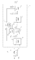
- FIG. 1 is a schematic diagram of a hydrocarbon production apparatus 1 according to Embodiment 1.
- the hydrocarbon production apparatus 1 includes a synthesis gas production section 2 , a hydrocarbon production section 4 , a first separation section 6 , a second separation section 8 and a third separation section 10 .
- the synthesis gas production unit 2 is arranged upstream of the hydrocarbon production unit 4 .
- a second separation section 8 is arranged between the synthesis gas production section 2 and the hydrocarbon production section 4 .
- a first separation section 6 is arranged downstream of the hydrocarbon production section 4 .
- a third separation section 10 is arranged between the first separation section 6 and the synthesis gas production section 2 .
- the third separating section 10 is connected to the second separating section 8 .
- the synthesis gas production unit 2 is supplied with carbon dioxide and hydrogen as raw material gases. The carbon dioxide and hydrogen are then used to produce synthesis gas containing carbon monoxide and hydrogen. Oxygen is also supplied to the synthesis gas production unit 2, and the oxygen is also used for production of synthesis gas.
- the synthesis gas production unit 2 of the present embodiment receives supply of hydrogen and oxygen from the water electrolysis module 12 as an example.
- the water electrolysis module 12 is illustrated as an external device with respect to the hydrocarbon production apparatus 1 in FIG. 1, the water electrolysis module 12 may be incorporated inside the hydrocarbon production apparatus 1 .
- the water electrolysis module 12 is an electrolytic cell that generates hydrogen and oxygen by electrolyzing water.
- the water electrolysis module 12 has a structure in which an oxygen generating electrode having a catalyst such as iridium or platinum and a hydrogen generating electrode having a catalyst such as platinum are separated by a diaphragm having proton conductivity. That is, the water electrolysis module 12 is a solid polymer water electrolysis module.
- Other examples of the water electrolysis module 12 include an alkaline water electrolysis module and a solid oxide water electrolysis module.
- the reactions during electrolysis of water in the polymer electrolyte water electrolysis module are as shown in the following formulas (1) and (2). Reaction Occurring at the Oxygen Evolving Electrode: 2H 2 O ⁇ O 2 +4H + +4e ⁇ (1) Reaction occurring at hydrogen evolution electrode: 4H + +4e ⁇ ⁇ 2H 2 (2)
- the water electrolysis module 12 receives power necessary for water electrolysis from a power supply device (not shown).
- power supply devices include power generation devices that generate power using renewable energy, such as wind power generation devices and solar power generation devices. As a result, it is possible to reduce the amount of carbon dioxide emissions associated with the production of hydrogen and, in turn, the production of target hydrocarbons having 5 or more carbon atoms (hereinafter referred to as “C5+ components” as appropriate).
- the power supply device is not limited to a power generation device that uses renewable energy, and may be a grid power source, a renewable energy power generation device, or a power storage device that stores power from a grid power source. good. Also, a combination of two or more of these may be used.
- carbon dioxide supplied to the synthesis gas production unit 2 for example, carbon dioxide recovered from the atmosphere by direct air recovery (DAC) can be used. Further, carbon dioxide separated and recovered by, for example, a chemical absorption method or a physical absorption method can be used from flue gas discharged from a thermal power plant, a chemical plant, or the like. This is expected to reduce carbon dioxide in the atmosphere. Also, consumption of fossil fuels can be reduced.
- DAC direct air recovery
- the reaction shown in formula (3) occurs, hydrogen contained in the raw material gas is oxidized, and water is produced. Also, the reaction represented by the formula (4) occurs, and the carbon dioxide and hydrogen contained in the raw material gas react to produce carbon monoxide and water.
- the reaction shown in equation (3) is an exothermic reaction.
- the reaction represented by formula (4) is an endothermic reaction.
- the heat required for the reaction shown in formula (4) is covered by the heat generated in the reaction shown in formula (3).
- the synthesis gas production unit 2 generates carbon monoxide from carbon dioxide contained in the raw material gas by using heat generated by oxidation of hydrogen contained in the raw material gas.
- the oxidation of hydrogen provides the reaction heat necessary for the production of carbon monoxide. Coking in can be suppressed. As a result, it is possible to reduce the degree of demand for setting the mixability of the raw material gas and the optimum air-fuel ratio. Moreover, deterioration of the catalyst can be suppressed, and the service life of the catalyst can be extended. Therefore, the production efficiency of the C5+ component can be improved.
- synthesis gas may contain methane in addition to hydrogen and carbon monoxide. This methanation of carbon monoxide can be suppressed by adjusting the temperature of the synthesis gas production section 2 or the like. Syngas may also contain unreacted carbon dioxide.
- the synthesis gas discharged from the synthesis gas production unit 2 is sent to the second separation unit 8.
- the water discharged from the synthesis gas production unit 2 may be separated from the synthesis gas and supplied to, for example, the water electrolysis module 12 or the like.
- the second separation section 8 separates carbon dioxide from the synthesis gas.
- a known carbon dioxide separator can be used for the second separation section 8 .
- Carbon dioxide separated by the second separation unit 8 is supplied to the synthesis gas production unit 2 .
- the synthesis gas production unit 2 is supplied with the carbon dioxide separated by the second separation unit 8 and also uses the carbon dioxide to produce synthesis gas. This improves the utilization of carbon dioxide. Therefore, the production efficiency of the C5+ component can be improved.
- the synthesis gas from which carbon dioxide has been separated in the second separation section 8 is sent to the hydrocarbon production section 4 .
- the H 2 /CO ratio of the synthesis gas supplied to the hydrocarbon production unit 4 is, for example, 1.80-2.30, preferably 1.90-2.20, more preferably 2.00-2. .10.
- the hydrocarbon production unit 4 produces the target C5+ component using the supplied synthesis gas.
- the C5+ component is, for example, normal paraffin having 5 or more carbon atoms.
- the hydrocarbon production section 4 of the present embodiment is composed of a known FT reactor.
- a tubular fixed bed reactor, a slurry bed reactor, or the like can be used as the FT reactor.
- the reaction represented by the following formula (6) occurs, and C5+ components are produced by carbon-carbon chain growth.
- a cobalt catalyst, a precipitated iron catalyst, a ruthenium catalyst, or the like can be used as a catalyst for the FT reaction.
- the rate at which a reaction intermediate having n carbon atoms is heavier to a reaction intermediate having n+1 carbon atoms through carbon-carbon chain growth is expressed by the chain growth probability ⁇ .
- a higher ⁇ means that a higher molecular weight hydrocarbon can be obtained.
- ⁇ varies depending on the type of catalyst and reaction conditions, and is preferably 0.75 to 0.95, more preferably 0.85 to 0.95.
- n of the C5+ component contained at 0.1 mol % or more is an integer of 5 to 60, for example.
- light hydrocarbons such as methane, ethane, propane, and butane which are gaseous at normal temperature and pressure and have 4 or less carbon atoms (hereinafter referred to as “C4-component”) are also produced as by-products.
- C4-component light hydrocarbons such as methane, ethane, propane, and butane which are gaseous at normal temperature and pressure and have 4 or less carbon atoms
- the effluent from the hydrocarbon production section 4 is sent to the first separation section 6.
- This effluent can include not only C5+ and C4- components, but also other by-products such as water, unreacted hydrogen, carbon monoxide, and carbon dioxide.
- the first separation section 6 can be composed of a known gas-liquid separator and separates the effluent into a liquid component and a gaseous component.
- Liquid components include C5+ components and water.
- Gaseous components include hydrogen, carbon monoxide, carbon dioxide and C4-components.
- the gaseous component may contain gaseous C5+ component.
- the liquid components are separated into C5+ components and water by a known oil-water separator (not shown).
- the separated C5+ components undergo upgrade treatment such as hydrotreating as necessary to become hydrocarbon products that can be used as substitutes for kerosene, gas oil, and the like.
- the separated water may be supplied to the water electrolysis module 12 or the like, for example.
- the gas component is sent to the synthesis gas production section 2 as recycled gas.
- hydrogen, carbon monoxide and carbon dioxide are separated from the recycle gas by the third separation section 10 provided between the first separation section 6 and the synthesis gas production section 2 .
- a known gas separator can be used for the third separation section 10 .
- the third separation section 10 as an example performs separation using at least one of a pressure swing adsorption (PSA) method and a membrane separation method.
- PSA pressure swing adsorption
- the third separation section 10 uses the membrane separation method
- the third separation section 10 as an example has at least one of a polyimide film, a carbon film obtained by carbonizing the polyimide film, and a metal film containing Pd.
- the separated hydrogen, carbon monoxide and carbon dioxide are supplied to the second separation section 8 .
- the second separation section 8 separates carbon dioxide from hydrogen, carbon monoxide and carbon dioxide supplied from the third separation section 10 . Therefore, the gas supplied from the third separation section 10 is separated into hydrogen, carbon monoxide, and carbon dioxide. Carbon dioxide separated by the second separation unit 8 is supplied to the synthesis gas production unit 2 .
- the synthesis gas production unit 2 also uses the carbon dioxide to produce synthesis gas. This improves the utilization of carbon dioxide.
- the carbon monoxide and hydrogen separated by the second separation section 8 are supplied to the hydrocarbon production section 4 .
- the hydrocarbon production unit 4 also uses the hydrogen and carbon monoxide to produce C5+ components. This improves the utilization of hydrogen and carbon monoxide. Also, the H 2 /CO ratio of the syngas supplied to the hydrocarbon production section 4 can be adjusted to a value suitable for the FT reaction. Therefore, the production efficiency of the C5+ component can be improved.
- the recycled gas from which hydrogen, carbon monoxide and carbon dioxide are separated is sent to the synthesis gas production section 2 .
- Water is also supplied to the synthesis gas production unit 2, and the water is also used for production of synthesis gas.
- the reforming reaction shown in the following formula (7) occurs, and the C4-component contained in the recycle gas (formula ( 7), denoted as C n H m ) reacts with water to produce carbon monoxide and hydrogen.
- n is an integer of 1-4 and m is an integer of 4-10.
- an exothermic reaction shown in the following formula (8) may occur (formula (8) n and m in are the same as in formula (7)).
- the heat required for the endothermic reactions shown in equations (4) and (7) can be provided by the heat generated in the reaction shown in equation (8) in addition to the heat generated in the reaction shown in equation (3). .
- the synthesis gas production unit 2 receives the supply of the recycled gas and uses the C4-component contained in the recycled gas to produce the synthesis gas. This improves the utilization of the C4-component.
- the temperature of the synthesis gas production unit 2 reaches a temperature suitable for the reaction in the synthesis gas production unit 2. can reduce the energy required to raise the temperature of Therefore, the production efficiency of the C5+ component can be improved.
- FIG. 2 is a schematic diagram of a hydrocarbon production apparatus 1 according to Embodiment 2. As shown in FIG.
- the hydrocarbon production apparatus 1 of the present embodiment includes a reforming section 14 between the third separation section 10 and the synthesis gas production section 2 .
- the recycled gas from which hydrogen, carbon monoxide and carbon dioxide are separated in the third separation section 10 is sent to the reforming section 14 .
- the reforming section 14 the reactions of formulas (9) and (10) described below occur, and the C4- component contained in the recycle gas is reformed into methane.
- n is an integer of 1-4 and m is an integer of 4-10.
- reaction of formula (10) is an equilibrium reaction. Furthermore, in the reforming section 14, an equilibrium reaction represented by Equation (11), which will be described later, also occurs. Therefore, the gas generated in the reforming section 14 may contain carbon monoxide, carbon dioxide, hydrogen and water in addition to methane.
- a known reformer capable of reforming C4-components into methane can be used.
- a steam reformer can be used for the reforming section 14 .
- Water required for the reaction in the reforming section 14 is supplied from the outside, for example.
- the water produced in the synthesis gas production unit 2 and the hydrocarbon production unit 4 may be recycled and supplied to the reforming unit 14 .
- the reaction temperature of the reforming section 14 is, for example, 450°C to 600°C, preferably 450°C to 500°C.
- the recycled gas containing methane produced in the reforming section 14 is sent to the synthesis gas production section 2.
- the synthesis gas production unit 2 receives the supply of this recycled gas and uses the methane, hydrogen, carbon monoxide and carbon dioxide contained in the recycled gas to produce synthesis gas.
- the composition of the synthesis gas is made suitable for the reaction in the hydrocarbon production unit 4. Easy to adjust composition. Therefore, the production efficiency of the C5+ component can be improved.
- the reforming section 14 may be capable of performing a dry reforming reaction represented by the following formula (12). CH 4 +CO 2 ⁇ 2H 2 +2CO (12)
- the hydrocarbon production device 1 may not include the third separation section 10 .
- a recycle gas containing hydrogen, carbon monoxide, carbon dioxide and C4-components or methane is supplied to the synthesis gas production section 2 .
- FIG. 3 is a schematic diagram of a hydrocarbon production apparatus 1 according to Modification 2. As shown in FIG. Although FIG. 3 shows a structure in which the fourth separation section 16 is added to the hydrocarbon production apparatus 1 of Embodiment 1, the fourth separation section 16 is added to the hydrocarbon production apparatus 1 of Embodiment 2. You can also add
- the hydrocarbon production apparatus 1 may have a fourth separation section 16 that receives the supply of hydrogen, carbon monoxide and carbon dioxide from the third separation section 10 instead of the second separation section 8 .
- the fourth separation section 16 separates the hydrogen, carbon monoxide, and carbon dioxide supplied from the third separation section 10 into hydrogen, carbon monoxide, and carbon dioxide.
- a known carbon dioxide separator can be used for the fourth separation section 16 as in the case of the second separation section 8 .
- Carbon dioxide separated by the fourth separation unit 16 may be supplied to the synthesis gas production unit 2 .
- the reforming section 14 performs the dry reforming reaction represented by the above formula (12)
- the carbon dioxide separated by the fourth separation section 16 may be supplied to the reforming section 14 .
- Hydrogen and carbon monoxide separated in the fourth separation section 16 are supplied to the hydrocarbon production section 4 .
- the hydrocarbon production unit 4 also uses the hydrogen and carbon monoxide to produce C5+ components.
- the hydrocarbon production unit 4 may be composed of a known methanol synthesizer and methanol-gasoline reactor (hereinafter referred to as “MTG reactor” as appropriate) instead of the FT reactor.
- MTG reactor methanol-gasoline reactor
- a reaction represented by the following formula (13) occurs, and methanol is synthesized from synthesis gas containing hydrogen and carbon monoxide.
- the reactions of the following formulas (14) and (15) occur in the MTG reactor, and methanol is converted to the target hydrocarbon (in formula (15), as an example, Lower olefins are denoted as C n H 2n ) are obtained.
- n is an integer from 2 to 10, for example.
- the hydrocarbons obtained include olefins, paraffins, aromatics (aromatic hydrocarbons), naphthenes, and the like.
- CO+ 2H2 ⁇ CH3OH (13) CH 3 OH ⁇ 1 ⁇ 2CH 3 —O—CH 3 +1 ⁇ 2H 2 O (14) n/2CH 3 —O—CH 3 ⁇ C n H 2n +n/2H 2 O (15)
- the hydrocarbon production unit 4 may be composed of a known syngas-olefin reactor (hereinafter referred to as “STO reactor” as appropriate) instead of the FT reactor.
- STO reactor syngas-olefin reactor
- the reaction represented by the following formula (16) occurs, and the target hydrocarbon is obtained from the synthesis gas containing hydrogen and carbon monoxide.
- the obtained hydrocarbons mainly contain lower olefins (in formula (16), a lower olefin having n carbon atoms and one double bond is represented as C n H 2n ).
- n is an integer from 2 to 10, for example.
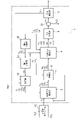
- FIG. 4 is a schematic diagram of a hydrocarbon production apparatus 1 according to Embodiment 3. As shown in FIG.
- the hydrocarbon production apparatus 1 includes a synthesis gas production section 2, a hydrocarbon production section 4, a first separation section 6, a second separation section 8, a product production section 18, a fifth separation section 20, a seventh A separation section 22 and a reforming section 14 are provided.
- the synthesis gas production unit 2 is arranged upstream of the hydrocarbon production unit 4 .
- a second separation section 8 is arranged between the synthesis gas production section 2 and the hydrocarbon production section 4 .
- a first separation section 6 is arranged downstream of the hydrocarbon production section 4 .
- a product manufacturing section 18 is arranged on the downstream side of the first separating section 6 .
- a fifth separation section 20 , a seventh separation section 22 and a reforming section 14 are arranged between the first separation section 6 and the synthesis gas production section 2 .
- the fifth separation section 20 is connected to the hydrocarbon production section 4
- the seventh separation section 22 is connected to the second separation section 8 .
- the synthesis gas production unit 2 uses carbon dioxide and hydrogen to produce synthesis gas containing carbon monoxide and hydrogen.
- the synthesis gas production unit 2 receives supply of hydrogen from the water electrolysis module 12 as an example.
- the reverse shift reaction shown in the above formula (4) occurs, producing a synthesis gas containing at least carbon monoxide and hydrogen.
- the heat required for the reverse shift reaction is supplied from the outside, for example.
- some carbon monoxide can react with hydrogen to produce methane and water as shown in equation (5) above. Therefore, synthesis gas may contain methane in addition to hydrogen and carbon monoxide. Syngas may also contain unreacted carbon dioxide.
- the synthesis gas discharged from the synthesis gas production section 2 is sent to the second separation section 8 .
- the second separation section 8 separates carbon dioxide from the synthesis gas. Carbon dioxide separated by the second separation unit 8 is supplied to the synthesis gas production unit 2 .
- the synthesis gas production unit 2 is supplied with the carbon dioxide separated by the second separation unit 8 and also uses the carbon dioxide to produce synthesis gas.
- the synthesis gas from which carbon dioxide has been separated in the second separation section 8 is sent to the hydrocarbon production section 4 .
- the hydrocarbon production unit 4 produces C5+ components using the supplied synthesis gas. In the hydrocarbon production section 4, the reaction represented by the above formula (6) occurs, and the C5+ component is produced by carbon-carbon chain growth. In the hydrocarbon production section 4, C4-components are also produced as a by-product.
- the effluent from the hydrocarbon production section 4 is sent to the first separation section 6.
- the first separation section 6 can be composed of a known gas-liquid separator and separates the effluent into a liquid component and a gaseous component.
- Liquid components include C5+ components and water.
- Gaseous components include hydrogen, carbon monoxide, carbon dioxide and C4-components.
- the liquid component is separated into a C5+ component and water by a known oil-water separator 24.
- the separated C5+ component is sent to product manufacturing department 18 .
- the product manufacturing department 18 performs upgrading processes such as hydrotreating on the C5+ components supplied from the hydrocarbon manufacturing department 4 to manufacture hydrocarbon products that can be used as substitutes for kerosene, gas oil, and the like.
- the product manufacturing section 18 by-produces the C4-component together with the hydrocarbon product.
- the gas component is used as recycled gas.
- part of the recycle gas is directly returned from the first separation section 6 to the hydrocarbon production section 4 .
- the hydrocarbon production section 4 receives a part of the recycled gas supplied from the first separation section 6 and uses the recycled gas to produce the C5+ component.
- the conversion rate of carbon monoxide in one reaction in the hydrocarbon production section 4, that is, when the syngas is passed through the hydrocarbon production section 4 once, is, for example, about 50 to 60%. Returning a portion of the recycle gas from the first separation section 6 to the hydrocarbon production section 4 to increase the conversion rate to, for example, about 80-99%, or 85%-97%, or 90%-95%. can be done.
- the remaining recycle gas flowing out of the first separation section 6 is sent to the fifth separation section 20 provided between the first separation section 6 and the synthesis gas production section 2 .
- the fifth separation section 20 separates carbon monoxide from the recycled gas.
- a known separator that separates carbon monoxide by the PSA method, for example, can be used for the fifth separation section 20 .
- the carbon monoxide separated by the fifth separation section 20 is supplied to the hydrocarbon production section 4 .
- the hydrocarbon production unit 4 also uses the carbon monoxide to produce C5+ components. This improves the utilization rate of carbon monoxide and improves the production efficiency of C5+ components.
- the load applied to the seventh separation section 22 can be reduced, and an increase in the equipment scale of the seventh separation section 22 can be suppressed.
- the recycled gas from which carbon monoxide has been separated in the fifth separation section 20 is sent to the seventh separation section 22 provided between the fifth separation section 20 and the synthesis gas production section 2 .
- the seventh separation section 22 separates hydrogen and carbon dioxide from the recycle gas supplied from the fifth separation section 20 .
- a known separator that separates hydrogen and carbon dioxide by a membrane separation method, for example, can be used for the seventh separation unit 22 .
- the hydrogen and carbon dioxide separated by the seventh separation section 22 are supplied to the second separation section 8 . This improves the utilization of hydrogen and carbon dioxide and improves the production efficiency of C5+ components.
- the separation of hydrogen and carbon dioxide in the seventh separation section 22 can reduce the load on the reforming section 14 and suppress an increase in the scale of the facility. Therefore, process efficiency in the hydrocarbon production apparatus 1 can be improved.
- the second separation section 8 separates the hydrogen and carbon dioxide supplied from the seventh separation section 22 into hydrogen and carbon dioxide.
- the hydrogen separated by the second separation section 8 is supplied to the hydrocarbon production section 4 .
- the hydrocarbon production unit 4 also uses the hydrogen to produce C5+ components. This improves the utilization of hydrogen and improves the production efficiency of C5+ components.
- Carbon dioxide separated by the second separation unit 8 is supplied to the synthesis gas production unit 2 .
- the synthesis gas production unit 2 also uses the carbon dioxide to produce synthesis gas. This improves the utilization of carbon dioxide and improves the production efficiency of C5+ components.
- the recycle gas from which hydrogen and carbon dioxide are separated in the seventh separation section 22 is sent to the reforming section 14 provided between the seventh separation section 22 and the synthesis gas production section 2 .
- the reactions of the above formulas (9), (10) and (11) occur, and the C4-components contained in the recycled gas are reformed into methane, hydrogen, carbon monoxide and carbon dioxide.
- the recycled gas containing methane, hydrogen, carbon monoxide and carbon dioxide produced in the reforming section 14 is sent to the synthesis gas producing section 2 .
- the synthesis gas production unit 2 receives the supply of this recycled gas and uses the methane, hydrogen, carbon monoxide and carbon dioxide contained in the recycled gas to produce synthesis gas.
- the reaction temperature of the synthesis gas production unit 2 is 700° C. or higher, preferably 800° C. or higher, more preferably 1000° C. or higher
- the reverse reaction of the reaction shown in the above formula (5) produces synthesis gas from methane and water. It can be manufactured efficiently. This improves the utilization of the C4- component and improves the production efficiency of the C5+ component.
- the reforming section 14 is supplied with the C4- component by-produced in the product manufacturing section 18 .
- the reformer 14 also reforms the C4- component into methane, hydrogen, carbon monoxide and carbon dioxide. This improves the utilization of the C4- component and improves the production efficiency of the C5+ component.
- FIG. 5 is a schematic diagram of a hydrocarbon production apparatus 1 according to Modification 5. As shown in FIG. This modification has the same configuration as that of the third embodiment, except that the arrangement of the fifth separating section 20 and the seventh separating section 22 is reversed.
- a part of the recycle gas flowing out from the first separation section 6 is directly returned from the first separation section 6 to the hydrocarbon production section 4 .
- the hydrocarbon production section 4 receives a part of the recycled gas supplied from the first separation section 6 and uses the recycled gas to produce the C5+ component.
- the remaining recycled gas is sent to the seventh separation section 22 provided between the first separation section 6 and the synthesis gas production section 2 .
- the seventh separation section 22 separates hydrogen and carbon dioxide from the recycled gas.
- the hydrogen and carbon dioxide separated by the seventh separation section 22 are supplied to the second separation section 8 . Note that part of the carbon monoxide in the recycle gas can also be separated in the seventh separation section 22 .
- the second separation section 8 separates the hydrogen and carbon dioxide supplied from the seventh separation section 22 into hydrogen and carbon dioxide.
- the hydrogen separated by the second separation section 8 is supplied to the hydrocarbon production section 4 .
- the hydrocarbon production unit 4 also uses the hydrogen to produce C5+ components.
- Carbon dioxide separated by the second separation unit 8 is supplied to the synthesis gas production unit 2 .
- the synthesis gas production unit 2 also uses the carbon dioxide to produce synthesis gas.
- the recycle gas from which hydrogen and carbon dioxide are separated in the seventh separation section 22 is sent to the fifth separation section 20 provided between the seventh separation section 22 and the synthesis gas production section 2 .
- the fifth separation section 20 separates carbon monoxide from the recycle gas supplied from the seventh separation section 22 .
- the carbon monoxide separated by the fifth separation section 20 is supplied to the hydrocarbon production section 4 .
- the hydrocarbon production unit 4 also uses the carbon monoxide to produce C5+ components.
- the recycled gas from which carbon monoxide has been separated in the fifth separation section 20 is sent to the reforming section 14 provided between the fifth separation section 20 and the synthesis gas production section 2 .
- the reformer 14 reforms the C4-components contained in the recycle gas into methane, hydrogen, carbon monoxide and carbon dioxide. Further, the reforming section 14 is supplied with the C4- component by-produced in the product manufacturing section 18 .
- the reformer 14 also reforms the C4- component into methane, hydrogen, carbon monoxide and carbon dioxide.
- the recycled gas containing methane, hydrogen, carbon monoxide and carbon dioxide produced in the reforming section 14 is sent to the synthesis gas producing section 2 .
- the synthesis gas production unit 2 also uses methane, hydrogen, carbon monoxide and carbon dioxide contained in the recycled gas to produce synthesis gas.
- the reaction temperature of the synthesis gas production unit 2 is 700° C. or higher, preferably 800° C. or higher, more preferably 1000° C. or higher
- the reverse reaction of the reaction shown in the above formula (5) produces synthesis gas from methane and water. It can be manufactured efficiently.
- FIG. 6 is a schematic diagram of a hydrocarbon production apparatus 1 according to Embodiment 4. As shown in FIG. The present embodiment differs from the third embodiment in that the hydrocarbon production apparatus 1 includes a sixth separation section 26 instead of the seventh separation section 22 .
- a part of the recycle gas flowing out from the first separation section 6 is directly returned from the first separation section 6 to the hydrocarbon production section 4 .
- the hydrocarbon production section 4 receives a part of the recycled gas supplied from the first separation section 6 and uses the recycled gas to produce the C5+ component.
- the remaining recycled gas is sent to the fifth separation section 20 provided between the first separation section 6 and the synthesis gas production section 2 .
- the fifth separation section 20 separates carbon monoxide from the recycled gas.
- the carbon monoxide separated by the fifth separation section 20 is supplied to the hydrocarbon production section 4 .
- the hydrocarbon production unit 4 also uses the carbon monoxide to produce C5+ components.
- the load on the sixth separation section 26 can be reduced, and an increase in the scale of the sixth separation section 26 can be suppressed.
- the recycled gas from which carbon monoxide has been separated in the fifth separation section 20 is sent to the sixth separation section 26 provided between the fifth separation section 20 and the synthesis gas production section 2 .
- the sixth separation section 26 separates hydrogen from the recycle gas supplied from the fifth separation section 20 .
- a known separator that separates hydrogen by, for example, the PSA method or the membrane separation method can be used for the sixth separation unit 26 .
- the hydrogen separated by the sixth separation section 26 is supplied to the hydrocarbon production section 4 .
- the hydrocarbon production unit 4 also uses the hydrogen to produce C5+ components. This improves the utilization rate of hydrogen. Further, by separating hydrogen in the sixth separation section 26, the load on the reforming section 14 can be reduced, and an increase in the scale of the facility can be suppressed. Therefore, process efficiency in the hydrocarbon production apparatus 1 can be improved.
- the recycle gas from which hydrogen has been separated in the sixth separation section 26 is sent to the reforming section 14 provided between the sixth separation section 26 and the synthesis gas production section 2 .
- the reformer 14 reforms the C4-components contained in the recycle gas into methane, hydrogen, carbon monoxide and carbon dioxide. Further, the reforming section 14 is supplied with the C4- component by-produced in the product manufacturing section 18 .
- the reformer 14 also reforms the C4- component into methane, hydrogen, carbon monoxide and carbon dioxide.
- the recycled gas containing methane, hydrogen, carbon monoxide and carbon dioxide produced in the reforming section 14 is sent to the synthesis gas producing section 2 .
- the synthesis gas production unit 2 also uses methane, hydrogen, carbon monoxide and carbon dioxide contained in the recycled gas to produce synthesis gas.
- the reaction temperature of the synthesis gas production unit 2 is 700° C. or higher, preferably 800° C. or higher, more preferably 1000° C. or higher
- the reverse reaction of the reaction shown in the above formula (5) produces synthesis gas from methane and water. It can be manufactured efficiently.
- FIG. 7 is a schematic diagram of a hydrocarbon production apparatus 1 according to Modification 6. As shown in FIG. This modification has the same configuration as that of the fourth embodiment except that the arrangement of the fifth separation section 20 and the sixth separation section 26 is reversed.
- a part of the recycle gas flowing out from the first separation section 6 is directly returned from the first separation section 6 to the hydrocarbon production section 4 .
- the hydrocarbon production section 4 receives a part of the recycled gas supplied from the first separation section 6 and uses the recycled gas to produce the C5+ component.
- the remaining recycled gas is sent to the sixth separation section 26 provided between the first separation section 6 and the synthesis gas production section 2 .
- the sixth separation section 26 separates hydrogen from the recycle gas.
- the hydrogen separated by the sixth separation section 26 is supplied to the hydrocarbon production section 4 .
- the hydrocarbon production unit 4 also uses the hydrogen to produce C5+ components.
- the recycle gas from which hydrogen has been separated in the sixth separation section 26 is sent to the fifth separation section 20 provided between the sixth separation section 26 and the synthesis gas production section 2 .
- the fifth separation section 20 separates carbon monoxide from the recycle gas supplied from the sixth separation section 26 .
- the carbon monoxide separated by the fifth separation section 20 is supplied to the hydrocarbon production section 4 .
- the hydrocarbon production unit 4 also uses the carbon monoxide to produce C5+ components.
- the recycled gas from which carbon monoxide has been separated in the fifth separation section 20 is sent to the reforming section 14 provided between the fifth separation section 20 and the synthesis gas production section 2 .
- the reformer 14 reforms the C4-components contained in the recycle gas into methane, hydrogen, carbon monoxide and carbon dioxide. Further, the reforming section 14 is supplied with the C4- component by-produced in the product manufacturing section 18 .
- the reformer 14 also reforms the C4- component into methane, hydrogen, carbon monoxide and carbon dioxide.
- the recycled gas containing methane, hydrogen, carbon monoxide and carbon dioxide produced in the reforming section 14 is sent to the synthesis gas producing section 2 .
- the synthesis gas production unit 2 also uses methane, hydrogen, carbon monoxide and carbon dioxide contained in the recycled gas to produce synthesis gas.
- the reaction temperature of the synthesis gas production unit 2 is 700° C. or higher, preferably 800° C. or higher, more preferably 1000° C. or higher
- the reverse reaction of the reaction shown in the above formula (5) produces synthesis gas from methane and water. It can be manufactured efficiently.
- the present invention may be specified by the items described below.
- a synthesis gas production unit (2) that produces a synthesis gas containing carbon monoxide and hydrogen using carbon dioxide and hydrogen;
- a hydrocarbon production unit (4) that produces hydrocarbons (C5+) using synthesis gas;
- a first separation section (6) for separating recycle gas containing light hydrocarbons (C4-) having 4 or less carbon atoms from the effluent from the hydrocarbon production section (4);
- the synthesis gas production unit (2) receives the supply of the recycled gas and uses the recycled gas to produce the synthesis gas.
- the hydrocarbon production unit (4) receives a part of the recycled gas from the first separation unit (6), and uses the recycled gas to produce hydrocarbons (C5+).
- Syngas also contains carbon dioxide
- the hydrocarbon production device (1) comprises a second separation section (8) for separating carbon dioxide from the synthesis gas
- the synthesis gas production unit (2) receives the supply of carbon dioxide separated by the second separation unit (8), and uses the carbon dioxide to produce synthesis gas.
- the recycled gas also contains carbon monoxide
- the hydrocarbon production device (1) comprises a fifth separation section (20) for separating carbon monoxide from the recycle gas
- the hydrocarbon production unit (4) receives the supply of carbon monoxide separated by the fifth separation unit (20), and uses the carbon monoxide to produce hydrocarbons (C5+). 4.
- the hydrocarbon production apparatus according to any one of items 1 to 3.
- the recycled gas also contains hydrogen, carbon monoxide and carbon dioxide
- the hydrocarbon production device (1) comprises a third separation section (10) for separating hydrogen, carbon monoxide and carbon dioxide from the recycle gas
- the second separation section (8) receives supply of hydrogen, carbon monoxide and carbon dioxide from the third separation section (10), and converts the hydrogen, carbon monoxide and carbon dioxide into hydrogen and carbon monoxide and carbon dioxide. separates into carbon and
- the hydrocarbon production unit (4) receives the supply of hydrogen and carbon monoxide separated by the second separation unit (8), and uses the hydrogen and carbon monoxide to produce hydrocarbons (C5+). 4.
- a hydrocarbon production apparatus (1) according to item 3.
- the recycled gas also contains hydrogen, carbon monoxide and carbon dioxide
- the hydrocarbon production device (1) a third separation section (10) for separating hydrogen, carbon monoxide and carbon dioxide from the recycle gas; A fourth separation section that receives supply of hydrogen, carbon monoxide and carbon dioxide from the third separation section (10) and separates the hydrogen, carbon monoxide and carbon dioxide into hydrogen and carbon monoxide and carbon dioxide. (16) and The hydrocarbon production unit (4) receives the supply of hydrogen and carbon monoxide separated by the fourth separation unit (16), and uses the hydrogen and carbon monoxide to produce hydrocarbons (C5+). 4.
- a hydrocarbon production apparatus (1) according to any one of items 1 to 3.
- the recycled gas also contains hydrogen
- the hydrocarbon production device (1) comprises a sixth separation section (26) for separating hydrogen from the recycle gas
- the hydrocarbon production unit (4) receives the supply of hydrogen separated by the sixth separation unit (26), and uses the hydrogen to produce hydrocarbons (C5+). 4.
- a hydrocarbon production apparatus (1) according to any one of items 1 to 3.
- the recycled gas also contains hydrogen, carbon monoxide and carbon dioxide
- the hydrocarbon production device (1) a fifth separation section (20) for separating carbon monoxide from the recycled gas; a seventh separation section (22) that receives supply of the recycled gas from which carbon monoxide has been separated in the fifth separation section (20) and separates hydrogen and carbon dioxide from the recycled gas;
- the second separation unit (2) receives the supply of hydrogen and carbon dioxide separated by the seventh separation unit (22) and separates the hydrogen and carbon dioxide into hydrogen and carbon dioxide,
- the hydrocarbon production section (4) receives the carbon monoxide separated by the fifth separation section (20) and the hydrogen separated by the second separation section (2), and converts the carbon monoxide and hydrogen into hydrocarbons ( C5+) for use in the production of 4.
- the recycled gas also contains hydrogen and carbon monoxide
- the hydrocarbon production device (1) a fifth separation section (20) for separating carbon monoxide from the recycled gas; a sixth separation section (26) that receives supply of the recycled gas from which carbon monoxide has been separated in the fifth separation section (20) and separates hydrogen from the recycled gas;
- the hydrocarbon production section (4) receives the carbon monoxide separated by the fifth separation section (20) and the hydrogen separated by the sixth separation section (26), and converts the carbon monoxide and hydrogen into hydrocarbons ( C5+) for use in the production of 4.
- a hydrocarbon production apparatus (1) according to any one of items 1 to 3.
- the recycled gas also contains hydrogen, carbon monoxide and carbon dioxide
- the hydrocarbon production device (1) a seventh separation section (22) for separating hydrogen and carbon dioxide from the recycled gas; a fifth separation section (20) that receives supply of recycled gas from which hydrogen and carbon dioxide are separated in the seventh separation section (22) and separates carbon monoxide from the recycled gas;
- the second separation section (8) receives the supply of hydrogen and carbon dioxide separated by the seventh separation section (22) and separates the hydrogen and carbon dioxide into hydrogen and carbon dioxide,
- the hydrocarbon production section (4) receives the carbon monoxide separated by the fifth separation section (20) and the hydrogen separated by the second separation section (8), and converts the carbon monoxide and hydrogen into hydrocarbons ( C5+) for use in the production of 4.
- the recycled gas also contains hydrogen and carbon monoxide
- the hydrocarbon production device (1) a sixth separation section (26) for separating hydrogen from the recycled gas; a fifth separation section (20) that receives supply of recycled gas from which hydrogen has been separated in the sixth separation section (26) and separates carbon monoxide from the recycled gas;
- the hydrocarbon production section (4) receives the supply of the hydrogen separated by the sixth separation section (26) and the carbon monoxide separated by the fifth separation section (20), and converts the hydrogen and carbon monoxide into hydrocarbons ( C5+) for use in the production of 4.
- a hydrocarbon production apparatus (1) according to any one of items 1 to 3.
- the synthesis gas production unit (2) receives the supply of methane produced by the reforming unit (14) and also uses the methane to produce synthesis gas.
- a hydrocarbon production apparatus (1) according to any one of items 1 to 11.
- the hydrocarbon production device (1) includes a product production section (18) that receives supply of hydrocarbons (C5+) from the hydrocarbon production section (4) and produces hydrocarbon products,
- the product manufacturing department (18) by-produces light hydrocarbons (C4-) together with hydrocarbon products
- the reforming section (14) receives supply of light hydrocarbons (C4-) from the product manufacturing section (18) and reforms the light hydrocarbons (C4-) into methane, 13.
- a hydrocarbon production apparatus (1) according to item 12.
- a synthesis gas production process for producing a synthesis gas containing carbon monoxide and hydrogen using carbon dioxide and hydrogen;
- the recycled gas is supplied and used to produce synthesis gas.
- Hydrocarbon production method for producing a synthesis gas containing carbon monoxide and hydrogen using carbon dioxide and hydrogen
- a hydrocarbon production process for producing hydrocarbons (C5+) using synthesis gas
- a first separation step of separating a recycle gas containing light hydrocarbons (C4-) having 4 or less carbon atoms from the effluent from the hydrocarbon production process.
- the present invention can be used for hydrocarbon production equipment and hydrocarbon production methods.
- Hydrocarbon production device Syngas production department 4 Hydrocarbon production department 6 First separation part 8 Second separation part 10 Third separation part 12 Water electrolysis module 14 Reforming part 16 Fourth separation Division, 18 Product Manufacturing Division, 20 5th Separation Division, 22 7th Separation Division, 26 6th Separation Division.
Landscapes
- Chemical & Material Sciences (AREA)
- Organic Chemistry (AREA)
- Engineering & Computer Science (AREA)
- Oil, Petroleum & Natural Gas (AREA)
- Chemical Kinetics & Catalysis (AREA)
- General Chemical & Material Sciences (AREA)
- Combustion & Propulsion (AREA)
- Inorganic Chemistry (AREA)
- Materials Engineering (AREA)
- Metallurgy (AREA)
- Electrochemistry (AREA)
- Hydrogen, Water And Hydrids (AREA)
- Organic Low-Molecular-Weight Compounds And Preparation Thereof (AREA)
Priority Applications (4)
| Application Number | Priority Date | Filing Date | Title |
|---|---|---|---|
| JP2023529644A JPWO2022264676A1 (https=) | 2021-06-16 | 2022-04-18 | |
| EP22824671.6A EP4357326A4 (en) | 2021-06-16 | 2022-04-18 | Hydrocarbon production apparatus and hydrocarbon production process |
| AU2022294430A AU2022294430A1 (en) | 2021-06-16 | 2022-04-18 | Hydrocarbon production apparatus and hydrocarbon production method |
| US18/567,077 US20240271045A1 (en) | 2021-06-16 | 2022-04-18 | Hydrocarbon production apparatus and hydrocarbon production method |
Applications Claiming Priority (2)
| Application Number | Priority Date | Filing Date | Title |
|---|---|---|---|
| JP2021100350 | 2021-06-16 | ||
| JP2021-100350 | 2021-06-16 |
Publications (1)
| Publication Number | Publication Date |
|---|---|
| WO2022264676A1 true WO2022264676A1 (ja) | 2022-12-22 |
Family
ID=84527105
Family Applications (1)
| Application Number | Title | Priority Date | Filing Date |
|---|---|---|---|
| PCT/JP2022/018025 Ceased WO2022264676A1 (ja) | 2021-06-16 | 2022-04-18 | 炭化水素製造装置および炭化水素製造方法 |
Country Status (5)
| Country | Link |
|---|---|
| US (1) | US20240271045A1 (https=) |
| EP (1) | EP4357326A4 (https=) |
| JP (1) | JPWO2022264676A1 (https=) |
| AU (1) | AU2022294430A1 (https=) |
| WO (1) | WO2022264676A1 (https=) |
Cited By (1)
| Publication number | Priority date | Publication date | Assignee | Title |
|---|---|---|---|---|
| WO2023203895A1 (ja) * | 2022-04-18 | 2023-10-26 | Eneos株式会社 | 燃料製造装置および燃料製造方法 |
Citations (7)
| Publication number | Priority date | Publication date | Assignee | Title |
|---|---|---|---|---|
| JPS60124693A (ja) * | 1983-11-15 | 1985-07-03 | シエル・インターナシヨネイル・リサーチ・マーチヤツピイ・ベー・ウイ | 炭化水素の製造法 |
| US5324335A (en) * | 1986-05-08 | 1994-06-28 | Rentech, Inc. | Process for the production of hydrocarbons |
| JPH06184559A (ja) * | 1991-05-30 | 1994-07-05 | British Petroleum Co Plc:The | 改良されたガス変換法 |
| JP2008248179A (ja) | 2007-03-30 | 2008-10-16 | Kitakyushu Foundation For The Advancement Of Industry Science & Technology | 一酸化炭素の還元による炭化水素の製造方法 |
| JP2014517806A (ja) * | 2011-02-22 | 2014-07-24 | アレバ | 改質段階を含み、動作条件が選択的に調整される、炭素材料からメタノール又は炭化水素を製造する方法 |
| JP2015517586A (ja) * | 2012-05-09 | 2015-06-22 | エクスパンダー エナジー インコーポレイテッド | Gtl環境での炭化水素燃料の調合のためのフィッシャー・トロプシュ法の改良 |
| WO2019021129A1 (en) * | 2017-07-27 | 2019-01-31 | Sabic Global Technologies B.V. | APPARATUS AND METHOD RELATED TO THE USE OF SYNTHESIS GAS IN OLEFIN PRODUCTION |
Family Cites Families (4)
| Publication number | Priority date | Publication date | Assignee | Title |
|---|---|---|---|---|
| KR101318966B1 (ko) * | 2005-03-16 | 2013-10-17 | 퓨얼코어 엘엘씨 | 합성 탄화수소 화합물 제조를 위한 시스템, 방법 및 조성물 |
| FI20105503L (fi) * | 2010-05-10 | 2011-11-11 | Neste Oil Oyj | Menetelmä hiilivetykoostumuksen tuottamiseksi |
| EP3670443A1 (de) * | 2018-12-20 | 2020-06-24 | Forschungszentrum Jülich GmbH | Verfahren und vorrichtung zur herstellung von flüssigem kraftstoff |
| US11649163B2 (en) * | 2019-04-08 | 2023-05-16 | Haldor Topsøe A/S | Chemical synthesis plant |
-
2022
- 2022-04-18 EP EP22824671.6A patent/EP4357326A4/en active Pending
- 2022-04-18 JP JP2023529644A patent/JPWO2022264676A1/ja active Pending
- 2022-04-18 WO PCT/JP2022/018025 patent/WO2022264676A1/ja not_active Ceased
- 2022-04-18 US US18/567,077 patent/US20240271045A1/en active Pending
- 2022-04-18 AU AU2022294430A patent/AU2022294430A1/en not_active Abandoned
Patent Citations (7)
| Publication number | Priority date | Publication date | Assignee | Title |
|---|---|---|---|---|
| JPS60124693A (ja) * | 1983-11-15 | 1985-07-03 | シエル・インターナシヨネイル・リサーチ・マーチヤツピイ・ベー・ウイ | 炭化水素の製造法 |
| US5324335A (en) * | 1986-05-08 | 1994-06-28 | Rentech, Inc. | Process for the production of hydrocarbons |
| JPH06184559A (ja) * | 1991-05-30 | 1994-07-05 | British Petroleum Co Plc:The | 改良されたガス変換法 |
| JP2008248179A (ja) | 2007-03-30 | 2008-10-16 | Kitakyushu Foundation For The Advancement Of Industry Science & Technology | 一酸化炭素の還元による炭化水素の製造方法 |
| JP2014517806A (ja) * | 2011-02-22 | 2014-07-24 | アレバ | 改質段階を含み、動作条件が選択的に調整される、炭素材料からメタノール又は炭化水素を製造する方法 |
| JP2015517586A (ja) * | 2012-05-09 | 2015-06-22 | エクスパンダー エナジー インコーポレイテッド | Gtl環境での炭化水素燃料の調合のためのフィッシャー・トロプシュ法の改良 |
| WO2019021129A1 (en) * | 2017-07-27 | 2019-01-31 | Sabic Global Technologies B.V. | APPARATUS AND METHOD RELATED TO THE USE OF SYNTHESIS GAS IN OLEFIN PRODUCTION |
Non-Patent Citations (1)
| Title |
|---|
| See also references of EP4357326A4 |
Cited By (1)
| Publication number | Priority date | Publication date | Assignee | Title |
|---|---|---|---|---|
| WO2023203895A1 (ja) * | 2022-04-18 | 2023-10-26 | Eneos株式会社 | 燃料製造装置および燃料製造方法 |
Also Published As
| Publication number | Publication date |
|---|---|
| EP4357326A4 (en) | 2025-06-04 |
| EP4357326A1 (en) | 2024-04-24 |
| JPWO2022264676A1 (https=) | 2022-12-22 |
| US20240271045A1 (en) | 2024-08-15 |
| AU2022294430A1 (en) | 2024-02-01 |
Similar Documents
| Publication | Publication Date | Title |
|---|---|---|
| JP7837944B2 (ja) | 炭化水素の合成プロセス | |
| US20230234842A1 (en) | Chemical synthesis plant | |
| GB2593179A (en) | Production of hydrocarbons | |
| JP7743210B2 (ja) | 炭化水素製造装置および炭化水素製造方法 | |
| US9315452B2 (en) | Process for co-producing commercially valuable products from byproducts of fischer-tropsch process for hydrocarbon fuel formulation in a GTL environment | |
| KR20230134127A (ko) | 연료 합성을 위한 co2 및 증기로부터의 합성 가스 제조 | |
| CN121847002A (zh) | 化学合成设备 | |
| JP2025541768A (ja) | 炭化水素の合成プロセス | |
| US6993911B2 (en) | System for power generation in a process producing hydrocarbons | |
| CA2872194C (en) | Process for co-producing commercially valuable products from byproducts of fischer-tropsch process for hydrocarbon fuel formulation in a gtl environment | |
| WO2022264676A1 (ja) | 炭化水素製造装置および炭化水素製造方法 | |
| JP2024538349A (ja) | 燃料生成システムおよび方法 | |
| WO2023203895A1 (ja) | 燃料製造装置および燃料製造方法 | |
| US12618011B2 (en) | Process for synthesising hydrocarbons | |
| CN104150441A (zh) | 一种费托合成尾气转化为费托合成原料气的方法 | |
| CA3127978C (en) | Chemical synthesis plant | |
| WO2025119922A1 (en) | Process | |
| GB2637133A (en) | Process | |
| WO2025163280A1 (en) | A method and system for synthesising hydrocarbons | |
| EA050687B1 (ru) | Преобразование исходного углеводородного газа в синтез-газ для производства углеводородов | |
| HK40076324B (zh) | 制备合成气的方法 |
Legal Events
| Date | Code | Title | Description |
|---|---|---|---|
| 121 | Ep: the epo has been informed by wipo that ep was designated in this application |
Ref document number: 22824671 Country of ref document: EP Kind code of ref document: A1 |
|
| WWE | Wipo information: entry into national phase |
Ref document number: 2023529644 Country of ref document: JP |
|
| WWE | Wipo information: entry into national phase |
Ref document number: 2022294430 Country of ref document: AU Ref document number: 2022824671 Country of ref document: EP Ref document number: AU2022294430 Country of ref document: AU |
|
| NENP | Non-entry into the national phase |
Ref country code: DE |
|
| ENP | Entry into the national phase |
Ref document number: 2022294430 Country of ref document: AU Date of ref document: 20220418 Kind code of ref document: A |
|
| ENP | Entry into the national phase |
Ref document number: 2022824671 Country of ref document: EP Effective date: 20240116 |