WO2022264336A1 - 制御装置及び制御システム - Google Patents
制御装置及び制御システム Download PDFInfo
- Publication number
- WO2022264336A1 WO2022264336A1 PCT/JP2021/022927 JP2021022927W WO2022264336A1 WO 2022264336 A1 WO2022264336 A1 WO 2022264336A1 JP 2021022927 W JP2021022927 W JP 2021022927W WO 2022264336 A1 WO2022264336 A1 WO 2022264336A1
- Authority
- WO
- WIPO (PCT)
- Prior art keywords
- safe operation
- control
- control device
- unit
- industrial machine
- Prior art date
- Legal status (The legal status is an assumption and is not a legal conclusion. Google has not performed a legal analysis and makes no representation as to the accuracy of the status listed.)
- Ceased
Links
Images

Classifications
-
- G—PHYSICS
- G05—CONTROLLING; REGULATING
- G05B—CONTROL OR REGULATING SYSTEMS IN GENERAL; FUNCTIONAL ELEMENTS OF SUCH SYSTEMS; MONITORING OR TESTING ARRANGEMENTS FOR SUCH SYSTEMS OR ELEMENTS
- G05B19/00—Program-control systems
- G05B19/02—Program-control systems electric
- G05B19/18—Numerical control [NC], i.e. automatically operating machines, in particular machine tools, e.g. in a manufacturing environment, so as to execute positioning, movement or co-ordinated operations by means of program data in numerical form
- G05B19/4155—Numerical control [NC], i.e. automatically operating machines, in particular machine tools, e.g. in a manufacturing environment, so as to execute positioning, movement or co-ordinated operations by means of program data in numerical form characterised by program execution, i.e. part program or machine function execution, e.g. selection of a program
-
- G—PHYSICS
- G05—CONTROLLING; REGULATING
- G05B—CONTROL OR REGULATING SYSTEMS IN GENERAL; FUNCTIONAL ELEMENTS OF SUCH SYSTEMS; MONITORING OR TESTING ARRANGEMENTS FOR SUCH SYSTEMS OR ELEMENTS
- G05B19/00—Program-control systems
- G05B19/02—Program-control systems electric
- G05B19/18—Numerical control [NC], i.e. automatically operating machines, in particular machine tools, e.g. in a manufacturing environment, so as to execute positioning, movement or co-ordinated operations by means of program data in numerical form
- G05B19/406—Numerical control [NC], i.e. automatically operating machines, in particular machine tools, e.g. in a manufacturing environment, so as to execute positioning, movement or co-ordinated operations by means of program data in numerical form characterised by monitoring or safety
- G05B19/4061—Avoiding collision or forbidden zones
-
- G—PHYSICS
- G05—CONTROLLING; REGULATING
- G05B—CONTROL OR REGULATING SYSTEMS IN GENERAL; FUNCTIONAL ELEMENTS OF SUCH SYSTEMS; MONITORING OR TESTING ARRANGEMENTS FOR SUCH SYSTEMS OR ELEMENTS
- G05B19/00—Program-control systems
- G05B19/02—Program-control systems electric
- G05B19/18—Numerical control [NC], i.e. automatically operating machines, in particular machine tools, e.g. in a manufacturing environment, so as to execute positioning, movement or co-ordinated operations by means of program data in numerical form
- G05B19/414—Structure of the control system, e.g. common controller or multiprocessor systems, interface to servo, programmable interface controller
-
- G—PHYSICS
- G05—CONTROLLING; REGULATING
- G05B—CONTROL OR REGULATING SYSTEMS IN GENERAL; FUNCTIONAL ELEMENTS OF SUCH SYSTEMS; MONITORING OR TESTING ARRANGEMENTS FOR SUCH SYSTEMS OR ELEMENTS
- G05B2219/00—Program-control systems
- G05B2219/30—Nc systems
- G05B2219/49—Nc machine tool, till multiple
- G05B2219/49141—Detect near collision and slow, stop, inhibit movement tool
Definitions
- the present invention relates to a control device and a control system, and more particularly to a control device and a control system that cooperate with a cooperative application running on a general-purpose OS of a PC.
- Advanced applications include, for example, machine collision avoidance during machining (interference checking), monitoring of peripheral devices (eg, tool breakage detection, etc.), and machine learning applications.
- the control device when using the machine collision prevention function, sends the preceding position information during machining to the PC. Then, the PC side performs an interference check based on the preceding position. Then, when the occurrence of interference is detected, that fact is transmitted to the control device. The control device stops the movement of the machining axis based on the result of the interference check sent from the PC.
- a general-purpose OS that does not guarantee real-time processing does not guarantee real-time processing by applications. For this reason, the PC may not be able to send the processing result in time for the processing execution request from the control device. For example, if the PC cannot transmit an interference detection signal to the control device, the control device has no choice but to continue machining while the interference check is substantially disabled. In the worst case, the moving parts of the machine may collide with obstacles such as workpieces and jigs. Therefore, a mechanism for monitoring the processing status of applications running on a general-purpose OS from a control device is desired.
- a control system periodically transmits information related to processing of an application that cooperates with control of an industrial machine that operates on a general-purpose OS of a PC (hereinafter referred to as a cooperative application) to a control device.
- the control device monitors the time interval at which information is transmitted from the PC, and determines that the processing on the PC side is behind the control device when a predetermined threshold value is exceeded.
- the control device performs control based on a control command of a safety operation registered in advance, such as an operation to stop the operation of the machine, an operation to suppress the movement speed, an operation to wait for retraction, and the like.
- one aspect of the present disclosure is a control device that controls an industrial machine based on a control program, an application that runs on a general-purpose OS of a PC, and a cooperative application related to control of the industrial machine.
- a command analysis unit that analyzes the blocks of the control program and creates command data based on the commands of the blocks, and a predetermined operating state of the industrial machine a safe operation command storage unit in which safe operation command data for transitioning to a safe state is stored in advance; a reception interval monitoring unit that monitors; a reception interval determination unit that compares the reception interval of regular transmission information with a predetermined threshold value and determines whether the reception interval exceeds the threshold value; If the reception interval is equal to or less than the threshold based on the determination result by the determination unit, the command data generated by the command analysis unit is selected to be used for controlling the industrial machine, and the reception interval is equal to or less than the threshold value.
- a control command selection unit that selects to use the safe operation command data stored in
- control device that controls an industrial machine based on a control program, and a PC running a cooperative application that is an application running on a general-purpose OS and related to control of the industrial machine.
- control device includes a command analysis unit that analyzes blocks of the control program and creates command data based on commands of the blocks; and an operation state of the industrial machine.
- a safe operation command storage unit in which safe operation command data for transitioning to a predetermined safe state is stored in advance; a reception interval monitoring unit that monitors the interval; a reception interval determination unit that compares the reception interval of the periodic transmission information with a predetermined threshold value and determines whether the reception interval exceeds the threshold value; If the reception interval is equal to or less than the threshold based on the determination result by the reception interval determination unit, selecting to use the command data created by the command analysis unit for controlling the industrial machine, and determining the reception interval.
- a control command selection unit that selects to use the safe operation command data stored in the safe operation command storage unit for controlling the industrial machine, and the control command selection unit a control unit that controls the industrial machine based on the selected command data, wherein the PC controls the state of the control device or the state of the industrial machine in order to process the cooperative application.
- a state monitoring unit that transmits request information for reading at least one of them to the control device, and monitors at least one of the state of the control device and the state of the industrial machine based on the result; and the cooperative application.
- a processing result transmitting unit configured to transmit the processing result of (1) to the control device.
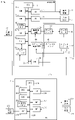
- FIG. 1 is a schematic hardware configuration diagram of a control system according to one embodiment of the present invention
- FIG. 1 is a block diagram showing the general functionality of a control system according to an embodiment of the invention
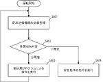
- FIG. 4 is a schematic flow chart illustrating the operational flow of a control system according to one embodiment of the present invention
- FIG. 1 is a schematic hardware configuration diagram showing essential parts of a control device according to an embodiment of the present invention.
- the control device 1 of the present invention constitutes a control system 4 together with a PC 2, which is an installed personal computer.
- a control device 1 controls an industrial machine 3 such as a machine tool or a machining center.
- the control device 1 cooperates with a cooperative application that provides a machine collision prevention function (interference check function) running on the general-purpose OS of the PC 2 .
- a machine collision prevention function interference check function
- the CPU 11 included in the control device 1 is a processor that controls the control device 1 as a whole.
- the CPU 11 reads a system program stored in the ROM 12 via the bus 22 and controls the entire control device 1 according to the system program.
- the RAM 13 temporarily stores calculation data, display data, various data input from the outside, and the like.
- the non-volatile memory 14 is composed of, for example, a memory backed up by a battery (not shown) or an SSD (Solid State Drive), and retains the stored state even when the control device 1 is powered off.
- the nonvolatile memory 14 stores control programs and data read from an external device 72 via the interface 15 , control programs and data input from the input device 71 via the interface 18 , and fog computer data via the network 5 . Control programs, data, and the like acquired from other devices such as 6 and cloud server 7 are stored.
- the data stored in the nonvolatile memory 14 includes, for example, data related to the mechanical configuration of the industrial machine 3, data related to interfering objects such as workpieces and jigs, data related to movement of the moving part along each axis, and other data.
- the control program and data stored in the nonvolatile memory 14 may be developed in the RAM 13 at the time of execution/use.
- Various system programs such as a well-known analysis program are pre-written in the ROM 12 .
- the interface 15 is an interface for connecting the CPU 11 of the control device 1 and an external device 72 such as an external storage medium. From the external device 72 side, for example, a control program and setting data used for controlling the industrial machine 3 are read. Control programs and setting data edited in the control device 1 can be stored in an external storage medium such as a CF card or USB memory (not shown) via the external device 72 .
- a PLC (Programmable Logic Controller) 16 executes a ladder program to control the industrial machine 3 and peripheral devices of the industrial machine 3 (for example, a tool changer, an actuator such as a robot, etc., attached to the industrial machine 3). (sensors, etc.) via the I/O unit 19 for control. It also receives signals from various switches on the operation panel and peripheral devices provided on the main body of the industrial machine 3 , performs necessary signal processing, and then transfers the signals to the CPU 11 .
- the interface 20 is an interface for wired or wireless connection between the CPU of the control device 1 and the PC 2 .
- the connection between the control device 1 and the PC 2 is, for example, serial communication such as RS-485, Ethernet (registered trademark) communication, optical communication, wireless LAN, Wi-Fi (registered trademark), Bluetooth (registered trademark), and other technologies. may be used for communication.
- the control device 1 exchanges data with the PC 2 via the interface 20 .
- each data read into the memory, data obtained as a result of executing the program, etc. are output via the interface 17 and displayed.
- An input device 71 composed of a keyboard, a pointing device, and the like passes commands, data, and the like based on operations by the operator to the CPU 11 via the interface 18 .
- the axis control circuit 30 for moving the moving part provided in the industrial machine 3 receives the movement command amount from the CPU 11 and outputs the movement command to the servo amplifier 40 respectively.
- the servo amplifier 40 receives this command and drives the servo motors 50 provided in the industrial machine 3 .
- the servo motor 50 incorporates a position/velocity detector, and feeds back a position/velocity feedback signal from this position/velocity detector to the axis control circuit 30 to perform position/velocity feedback control.
- Only one axis control circuit 30, one servo amplifier 40, and one servomotor 50 are shown in the hardware configuration diagram of FIG. Only the number of copies is prepared.
- a spindle control circuit 60 receives a spindle rotation command and outputs a spindle speed signal to a spindle amplifier 61 .
- the spindle amplifier 61 receives this spindle speed signal, rotates the spindle motor 62 of the industrial machine at the commanded rotational speed, and drives the tool.
- a position coder 63 is coupled to the spindle motor 62 , the position coder 63 outputs feedback pulses in synchronization with the rotation of the main shaft, and the feedback pulses are read by the CPU 11 .
- the PC 2 is installed together with the control device 1 .
- a CPU 211 included in the PC 2 is a processor that controls the PC 2 as a whole.
- the CPU 211 reads the system program stored in the ROM 212 via the bus 222 and controls the entire PC 2 according to the system program.
- the RAM 213 temporarily stores calculation data, display data, various data input from the outside, and the like.
- the non-volatile memory 214 is composed of, for example, a memory backed up by a battery (not shown) or an SSD (Solid State Drive), etc., and retains the memory state even when the power of the PC 2 is turned off.
- the nonvolatile memory 214 stores data acquired from the control device 1 via the interface 219, data and programs read from the external device 272 via the interface 215, data and programs input via the input device 271, and the like. is stored.
- the data and programs stored in the nonvolatile memory 214 may be developed in the RAM 213 during execution/use.
- the ROM 212 is pre-written with various system programs such as known processing programs, analysis programs, 3D simulation programs, machine collision prevention application programs, and the like.
- the interface 215 is an interface for connecting the CPU 211 of the PC 2 and an external device 272 such as a USB device. From the external device 272 side, for example, programs and parameters used for analysis can be read. Programs edited in the PC 2 and parameters can be stored in the external storage means via the external device 272 .
- the interface 219 is an interface for connecting the CPU 211 of the PC 2 and the control device 1 by wire or wirelessly.
- the PC 2 exchanges data with the control device 1 via the interface 219 .
- each data read into the memory data obtained as a result of executing the control program, system program, etc. are output and displayed via the interface 217.
- An input device 271 composed of a keyboard, a pointing device, and the like passes commands, data, and the like based on the operator's operation to the CPU 211 via the interface 218 .
- FIG. 2 is a schematic block diagram showing the functions provided by the control device 1 and the PC 2 according to the first embodiment of the present invention.
- Each function provided in the control device 1 according to the present embodiment is realized by the CPU 11 provided in the control device 1 shown in FIG.
- Each function of the PC 2 according to this embodiment is realized by the CPU 211 of the PC 2 shown in FIG. 1 executing the system program and controlling the operation of each part of the PC 2 .
- the control device 1 of this embodiment includes a command analysis unit 110, a control command selection unit 115, a control unit 120, a reception interval monitoring unit 125, and a reception interval determination unit .
- the PC 2 also includes a state monitoring section 210 , an application execution section 220 and a processing result transmission section 230 .
- a safe operation command storage unit 170 which is an area for pre-storing commands related to safe operation of the industrial machine 3
- a state information storage unit 180 which is an area for storing information indicating the control state of the industrial machine 3, is prepared, and a control program 190 used for controlling the industrial machine 3 is stored in advance.
- the command analysis unit 110 reads commands block by block from the control program 190, analyzes the commands, and creates data in an executable format. Command analysis unit 110 outputs command data in an executable format to control command selection unit 115 .
- the control command selection unit 115 determines the interval at which the reception interval determination unit 130 receives information (hereinafter referred to as periodical transmission information) created by the processing of an application that cooperates with the control of the industrial machine 3 and is periodically transmitted from the PC. is equal to or less than a predetermined threshold value, command analysis unit 110 outputs command data in an executable format created by analyzing the command to control unit 120 .
- the control command selection unit 115 reads the safety command read from the safety operation command storage unit 170 . It outputs command data related to the operation command to the control unit 120 .
- periodic transmission information that is, information created in the processing of a linked application includes request commands created to acquire information required for processing by the linked application, and information created and output by the linked application. include.
- the safe operation command storage unit 170 stores in advance command data relating to safe operation for shifting the operating state of the industrial machine 3 to a predetermined safe state.
- the safety operation includes, for example, a stop operation for safely stopping the operation of the industrial machine 3, a speed suppression operation for reducing the moving speed of the moving part of the industrial machine 3, a retraction standby operation for retracting the tool from the workpiece and standing by, PC2
- a switching operation to a function built in the control device 1 for a function linked to the control device 1 is exemplified.
- the command data relating to these safe operations may be created in advance according to the characteristics of the industrial machine 3 to be controlled and the content of the control program 190 and stored in the safe operation command storage unit 170 .
- the control command selection unit 115 selects, in addition to the executable command data created by the command analysis unit 110, the cooperative application transmitted from the PC 2.
- Information related to the processing result may be output to the control unit 120 .
- a cooperative application for the machine collision prevention function is running on PC2, and the results of interference checks between moving parts such as spindles and tools and interfering objects such as workpieces, jigs and tables are periodically sent. Suppose you come. In this case, the control command selection unit 115 outputs the result of the interference check to the control unit 120 in addition to the executable command data created by the command analysis unit 110 .
- the control unit 120 controls the industrial machine 3 based on data related to commands input from the control command selection unit 115 . For example, when command data for moving or stopping the moving part of the industrial machine 3 along an axis is input, the control part 120 outputs movement command data for driving the servo motor 50 that drives the axis. Further, the control unit 120 outputs rotation command data for controlling the spindle motor 62, for example, when command data for rotating or stopping the main shaft of the industrial machine 3 is input. In addition, the control unit 120 has functions for general control required to control the industrial machine 3 based on input command data. The results of the processing related to the control of the industrial machine 3 by the control unit 120 are sequentially stored in the state information storage unit 180 .
- the state information storage unit 180 stores, for example, the position and speed of the moving part of the industrial machine 3, the rotation state of the main shaft, the type of tool, the state of peripheral equipment such as a cutting fluid supply device and a machine door.
- the state information storage unit 180 also stores information such as the preceding position of the moving unit that performs the interference check. You can leave it.
- the control unit 120 may refer to the information and use it to control the industrial machine 3. .
- a cooperative application for the machine collision prevention function is running on PC2, and the results of interference checks between moving parts such as spindles and tools and interfering objects such as workpieces, jigs and tables are periodically sent.
- the control unit 120 may control the operation of the industrial machine 3 to stop when the result of the interference check transmitted from the PC 2 indicates a collision between the moving unit and an interfering object.
- the reception interval monitoring unit 125 monitors the reception interval of the regular transmission information sent from the PC2.
- the reception interval monitoring unit 125 stores the reception time of the regular transmission information from the PC 2 as a history. Then, the time elapsed from the time when the last transmitted information was received is output to the reception interval determining section 130 .
- a plurality of pieces of periodical transmission information may be sent from the PC 2 .
- the control device 1 cooperates with the machine collision prevention function operating on the PC2 side
- the PC2 requests the preceding position of the moving part to be subjected to the interference check.
- the result of the interference check regarding the preceding position previously requested from the PC 2 is transmitted.
- the reception interval monitoring unit 125 may individually monitor the reception intervals of the preceding position request and the result of the interference check as regular transmission information.
- the receiving interval determining unit 130 determines that the receiving interval of the periodic transmission information sent from the receiving interval monitoring unit 125 exceeds a predetermined threshold value
- the receiving interval determining unit 130 sends the determination result to the control command selecting unit 115.
- the threshold may be multiple stepped values.
- reception interval determining section 130 outputs to control command selecting section 115 so that it can be grasped at what stage the threshold has been exceeded.
- the safe operation command storage unit 170 is previously stored with different safe operation command data corresponding to the threshold levels. Then, the control command selection unit 115 may output different command data for safe operation to the control unit 120 according to what stage of the threshold value has been exceeded.
- the reception interval monitoring unit 125 monitors a plurality of pieces of periodic transmission information
- different threshold values may be set for each piece of periodic transmission information.
- the safe operation command storage unit 170 stores in advance different safe operation command data corresponding to the types of regular transmission information, and the control command selection unit 115 determines which regular transmission information exceeds the threshold value.
- the command data for different safe operations may be output to the control unit 120 according to the conditions.
- the predetermined threshold used by the reception interval determination unit 130 may be set in advance as a fixed value as described above, or may be dynamically set according to the situation. For example, as in the control device 1 according to the present embodiment, when cooperating with a cooperative application of the machine collision prevention function that operates on the PC 2, the PC 2 acquires the preceding position and transmits the result of the interference check at that position. come. Therefore, the result of the interference check is received before the time when the moving part of the industrial machine 3 reaches this preceding position (hereinafter referred to as the preceding time) and before the moving part can stop before interference. There is a need. Therefore, the threshold used by reception interval determination section 130 is dynamically calculated based on the preceding time. More specifically, a value obtained by multiplying the preceding time by a predetermined coefficient ( ⁇ 1.0) is used as the threshold. By configuring in this way, it is possible to dynamically set an appropriate threshold value for the preceding position that changes depending on the situation.
- ⁇ 1.0 predetermined coefficient
- the state monitoring unit 210 included in the PC 2 monitors the state of the control device 1 periodically.
- the state monitoring unit 210 requests predetermined information stored in the state information storage unit 180 included in the control device 1, for example. Then, information on the state of the control device 1 obtained as a response to the request is output to the application execution unit 220 .
- the state monitoring unit 210 instructs the control device 1 to , and outputs the resulting preceding position of the moving part to the application execution part 220 .
- the application execution unit 220 runs various application programs on the general-purpose OS.
- the cooperative application executed by the application executing section 220 may execute processing using information input from the state monitoring section 210 . Also, the cooperative application may output the processing result to the processing result transmission unit 230 .
- the application execution unit 220 of this embodiment executes an application program that provides a machine collision avoidance function. This machine collision prevention function checks for interference between the moving part and interfering objects such as workpieces, jigs and tables based on the preceding position of the moving part of the industrial machine 3 input from the state monitoring part 210 . Then, the result of the interference check is output to the processing result transmission unit 230 .
- the processing result transmission unit 230 transmits the processing result of the cooperative application by the application execution unit 220 to the control device 1 .
- the processing result transmission unit 230 of the present embodiment transmits the execution result of the interference check by the cooperative application of the machine collision prevention function to the control device 1 .
- FIG. 3 is a schematic flow chart showing the flow of operations in the control device 1 according to this embodiment having the above configuration.
- the reception interval monitoring unit 125 receives a preceding position request from the state monitoring unit 210 provided in the PC 2 and each transmission of the interference check result is monitored as periodical transmission information (step SA01).
- the reception interval determination unit 130 compares the reception interval of each periodic transmission information monitored by the reception interval monitoring unit 125 with a predetermined threshold value (step SA02). If both are equal to or less than the threshold, the control command selection unit 115 outputs the execution format command data created by the command analysis unit 110 and the processing result of the interference check transmitted from the PC 2 to the control unit 120 .
- the control unit 120 controls the industrial machine 3 according to the input command data and the processing result of the interference check (step SA03).
- the control command selection unit 115 selects the safe operation stored in the safe operation command storage unit 170. It outputs command data to the control unit 120 .
- the controller 120 controls the industrial machine 3 to operate safely according to the input command data (step SA04). After executing the safety operation, the operation of the industrial machine 3 is continued or the operation of the industrial machine 3 is interrupted according to the content of the safety operation.
- control device 1 With the control device 1 having the above configuration, it is possible to shift the control of the industrial machine 3 to safe operation when the reception interval of the periodic transmission information periodically transmitted from the PC 2 is delayed. As a result, when a cooperative application on the PC side that runs on a general-purpose OS is used, it is possible to reduce the influence of problems such as operation delays and hang-ups on the PC side on the machine operation.
- the threshold value used for determining the reception interval step by step for example, when the reception interval of the periodic transmission information exceeds the threshold value, the moving speed of the moving part of the industrial machine 3 is suppressed step by step. It is possible to respond flexibly, such as temporarily stopping.
- the control command selection unit 115 when the reception interval determination unit 130 determines that the reception interval of regular transmission information transmitted from the PC 2 exceeds a predetermined threshold in advance, command data relating to different safety operations may be output to the control unit 120 according to the state of the control device 1, the state of the industrial machine 3, the state of the peripheral device, and the like.
- the safe operation command storage unit 170 stores in advance a plurality of safe operation command data respectively corresponding to the control states of the control device 1 .
- control command selection unit 115 can read from the state information storage unit 180 the position and speed of the moving part of the industrial machine 3, the rotation state of the main shaft, the type of tool, the cutting fluid supply device and the machine door. , the execution block number of the control program 190, the load state of the servo motor 50 and the spindle motor 62 fed back from the industrial machine 3, and the like. can.
- the present invention is not limited to the above-described examples of the embodiments, and can be implemented in various modes by adding appropriate modifications.
- the control device 1 cooperates with the cooperation application of the machine collision prevention function that operates on the PC 2 side was shown.
- it can also be linked with other linked applications.
- a cooperative application for detecting tool breakage can be run on the PC 2
- a peripheral device of the industrial machine 3 such as a sensor is connected to the PC 2
- the PC 2 can detect the broken state of the tool. can.
- the PC 2 side periodically transmits the broken state of the tool to the control device 1, and the reception interval monitoring section 125 of the control device 1 monitors this information as regular transmission information.
- the PC 2 executes a cooperative application related to machine learning, and the PC 2 cooperates with the control device 1 .
- the inside and the surroundings of the industrial machine 3 are captured by a plurality of cameras, etc., and the captured moving images are analyzed by a machine learning cooperative application on the PC 2 to analyze the operating state and the surrounding state, and the analysis results are sent to the control device 1.
- the industrial machine 3 may be made to take a safe action when the transmission of the analysis result from the PC 2 is delayed.
- control device 2 PC 3 industrial machine 4 control system 5 network 6 fog computer 7 cloud server 11
- CPU 12 ROMs 13 RAM 14 non-volatile memory 15, 17, 18, 20 interface 19 I/O unit 22 bus 30 axis control circuit 40
- servo amplifier 50 servo motor 60 spindle control circuit 61 spindle amplifier 62 spindle motor 63 position coder 70 display device 71 input device 72 external Equipment 110 Command analysis unit 115
- Control command selection unit 120 Control unit 125 Reception interval monitoring unit 130 Reception interval determination unit 170 Safe operation command storage unit 180
- State information storage unit 190 Control program 211 CPU 212 ROMs 213 RAM 214 nonvolatile memory 215, 217, 218, 219 interface 222 bus 270 display device 271 input device 272 external device 210 state monitoring unit 220 application execution unit 230 processing result transmission unit
Landscapes
- Engineering & Computer Science (AREA)
- Human Computer Interaction (AREA)
- Manufacturing & Machinery (AREA)
- Physics & Mathematics (AREA)
- General Physics & Mathematics (AREA)
- Automation & Control Theory (AREA)
- Numerical Control (AREA)
Abstract
Description
そこで、制御装置から汎用OS上で動作するアプリケーションの処理状況を監視する仕組みが望まれている。
上記課題を解決する。
図1は本発明の一実施形態による制御装置の要部を示す概略的なハードウェア構成図である。本発明の制御装置1は、併設されたパソコンであるPC2と共に制御システム4を構成する。制御装置1は、例えば工作機械やマシニングセンタなどの産業用機械3を制御する。以下では、制御装置1が、PC2の汎用OSの上で動作している機械衝突防止機能(干渉チェック機能)を提供する連携アプリケーションと連携しているものとして説明する。
制御装置1とPC2で動作する機械衝突防止機能との連携動作が開始されると、受信間隔監視部125は、PC2が備える状態監視部210からの先行位置の要求、及び処理結果送信部230からの干渉チェック結果の送信のそれぞれを定期送信情報として監視する(ステップSA01)。
例えば、上記実施形態では制御装置1がPC2側で動作する機械衝突防止機能の連携アプリケーションと連携する例を示した。しかしながら、その他の連携アプリケーションと連携させることもできる。例えば、工具折損を検知するための連携アプリケーションをPC2で動作させ、センサ等の産業用機械3の周辺装置とPC2を接続し、PC2側で工具の折損状態を検出する場合にも対応することができる。この場合、PC2側から定期的に工具の折損状態を制御装置1に対して送信し、この情報を定期送信情報として制御装置1の受信間隔監視部125で監視するようにすればよい。
2 PC
3 産業用機械
4 制御システム
5 ネットワーク
6 フォグコンピュータ
7 クラウドサーバ
11 CPU
12 ROM
13 RAM
14 不揮発性メモリ
15,17,18,20 インタフェース
19 I/Oユニット
22 バス
30 軸制御回路
40 サーボアンプ
50 サーボモータ
60 スピンドル制御回路
61 スピンドルアンプ
62 スピンドルモータ
63 ポジションコーダ
70 表示装置
71 入力装置
72 外部機器
110 指令解析部
115 制御指令選択部
120 制御部
125 受信間隔監視部
130 受信間隔判定部
170 安全動作指令記憶部
180 状態情報記憶部
190 制御用プログラム
211 CPU
212 ROM
213 RAM
214 不揮発性メモリ
215,217,218,219 インタフェース
222 バス
270 表示装置
271 入力装置
272 外部機器
210 状態監視部
220 アプリケーション実行部
230 処理結果送信部
Claims (8)
- 制御用プログラムに基づいて産業用機械を制御する制御装置であって、PCの汎用OS上で動作するアプリケーションであって前記産業用機械の制御に係る連携アプリケーションと連携して該産業用機械の制御をする制御装置において、
前記制御用プログラムのブロックを解析し、該ブロックの指令に基づく指令データを作成する指令解析部と、
前記産業用機械の動作状態を所定の安全な状態へと移行するための安全動作の指令データが予め記憶される安全動作指令記憶部と、
前記PCから送信される前記連携アプリケーションに係る処理で作成された定期送信情報の受信間隔を監視する受信間隔監視部と、
定期送信情報の前記受信間隔を予め定めた所定の閾値と比較し、該受信間隔が該閾値を超えているか否かを判定する受信間隔判定部と、
前記受信間隔判定部による判定結果に基づいて、前記受信間隔が前記閾値以下である場合には、前記指令解析部が作成した指令データを前記産業用機械の制御に用いることを選択し、前記受信間隔が前記閾値を超えた場合には、前記安全動作指令記憶部に記憶される安全動作の指令データを前記産業用機械の制御に用いることを選択する制御指令選択部と、
前記制御指令選択部が選択した指令データに基づいて前記産業用機械を制御する制御部と、
を備えた制御装置。 - 前記連携アプリケーションは、先行位置に基づいて干渉チェックを行う機械衝突防止機能のアプリケーションであり、
前記定期送信情報は、少なくとも前記連携アプリケーションからの前記干渉チェックの結果情報を含む、
請求項1に記載の制御装置。 - 前記安全動作は、前記産業用機械を安全に停止する停止動作、前記産業用機械の移動部の移動速度を低下させる速度抑制動作、前記産業用機械の工具をワークからリトラクトして待機するリトラクト待機動作、または前記制御装置の内部監視機能への切り替え動作のいずれかである、
請求項2に記載の制御装置。 - 前記安全動作指令記憶部には、前記定期送信情報の種類にそれぞれ対応した複数の安全動作の指令データが予め記憶されており、
前記制御指令選択部は、前記定期送信情報の受信間隔が前記閾値を超えた場合に、前記安全動作指令記憶部に記憶された複数の安全動作の指令データの中から前記定期送信情報の種類に応じた安全動作の指令データを選択する、
請求項1に記載の制御装置。 - 前記閾値として、複数の段階的な値が用意されており、
前記安全動作指令記憶部には、前記閾値の段階にそれぞれ対応した複数の安全動作の指令データが予め記憶されており、
前記制御指令選択部は、前記定期送信情報の受信間隔が前記閾値を超えた場合に、前記安全動作指令記憶部に記憶された複数の安全動作の指令データの中から前記閾値の段階に応じた安全動作の指令データを選択する、
請求項1に記載の制御装置。 - 前記閾値は、前記制御装置の状態又は前記産業用機械の状態に基づいて動的に算出される、
請求項1に記載の制御装置。 - 前記安全動作指令記憶部には、前記制御装置の状態又は前記産業用機械の状態にそれぞれ対応した複数の安全動作の指令データが予め記憶されており、
前記制御指令選択部は、前記定期送信情報の受信間隔が前記閾値を超えた場合に、前記安全動作指令記憶部に記憶された複数の安全動作の指令データの中から前記制御装置の状態又は前記産業用機械の状態に応じた安全動作の指令データを選択する、
請求項1に記載の制御装置。 - 制御用プログラムに基づいて産業用機械を制御する制御装置と、汎用OS上で動作するアプリケーションであって前記産業用機械の制御に係る連携アプリケーションが動作しているPCとが連携して構成される制御システムにおいて、
前記制御装置は、
前記制御用プログラムのブロックを解析し、該ブロックの指令に基づく指令データを作成する指令解析部と、
前記産業用機械の動作状態を所定の安全な状態へと移行するための安全動作の指令データが予め記憶される安全動作指令記憶部と、
前記PCから送信される前記連携アプリケーションに係る処理で作成された定期送信情報の受信間隔を監視する受信間隔監視部と、
定期送信情報の前記受信間隔を予め定めた所定の閾値と比較し、該受信間隔が該閾値を超えているか否かを判定する受信間隔判定部と、
前記受信間隔判定部による判定結果に基づいて、前記受信間隔が前記閾値以下である場合には、前記指令解析部が作成した指令データを前記産業用機械の制御に用いることを選択し、前記受信間隔が前記閾値を超えた場合には、前記安全動作指令記憶部に記憶される安全動作の指令データを前記産業用機械の制御に用いることを選択する制御指令選択部と、
前記制御指令選択部が選択した指令データに基づいて前記産業用機械を制御する制御部と、
を備え、
前記PCは、
前記連携アプリケーションの処理を行うために、前記制御装置に係る状態又は前記産業用機械に係る状態の少なくともいずれかを読み出す要求情報を前記制御装置へと送信し、その結果に基づいて前記制御装置に係る状態又は前記産業用機械に係る状態の少なくともいずれかを監視する状態監視部と、
前記連携アプリケーションの処理の結果を前記制御装置に対して送信する処理結果送信部と、
を備える、
制御システム。
Priority Applications (5)
| Application Number | Priority Date | Filing Date | Title |
|---|---|---|---|
| DE112021007470.9T DE112021007470T5 (de) | 2021-06-16 | 2021-06-16 | Steuervorrichtung und steuersystem |
| US18/567,771 US20240272606A1 (en) | 2021-06-16 | 2021-06-16 | Control device and control system |
| CN202180099133.7A CN117425863A (zh) | 2021-06-16 | 2021-06-16 | 控制装置以及控制系统 |
| JP2023528861A JP7568853B2 (ja) | 2021-06-16 | 2021-06-16 | 制御装置及び制御システム |
| PCT/JP2021/022927 WO2022264336A1 (ja) | 2021-06-16 | 2021-06-16 | 制御装置及び制御システム |
Applications Claiming Priority (1)
| Application Number | Priority Date | Filing Date | Title |
|---|---|---|---|
| PCT/JP2021/022927 WO2022264336A1 (ja) | 2021-06-16 | 2021-06-16 | 制御装置及び制御システム |
Publications (1)
| Publication Number | Publication Date |
|---|---|
| WO2022264336A1 true WO2022264336A1 (ja) | 2022-12-22 |
Family
ID=84527311
Family Applications (1)
| Application Number | Title | Priority Date | Filing Date |
|---|---|---|---|
| PCT/JP2021/022927 Ceased WO2022264336A1 (ja) | 2021-06-16 | 2021-06-16 | 制御装置及び制御システム |
Country Status (5)
| Country | Link |
|---|---|
| US (1) | US20240272606A1 (ja) |
| JP (1) | JP7568853B2 (ja) |
| CN (1) | CN117425863A (ja) |
| DE (1) | DE112021007470T5 (ja) |
| WO (1) | WO2022264336A1 (ja) |
Cited By (1)
| Publication number | Priority date | Publication date | Assignee | Title |
|---|---|---|---|---|
| WO2026004168A1 (ja) * | 2024-06-28 | 2026-01-02 | Ntt株式会社 | 制御装置 |
Citations (3)
| Publication number | Priority date | Publication date | Assignee | Title |
|---|---|---|---|---|
| JP2006072399A (ja) * | 2004-08-31 | 2006-03-16 | Yaskawa Electric Corp | モーションコントロールシステム |
| JP2014059607A (ja) * | 2012-09-14 | 2014-04-03 | Toshiba Mach Co Ltd | 表示端末及び表示システム |
| JP2014191724A (ja) * | 2013-03-28 | 2014-10-06 | Mitsubishi Electric Corp | 入出力制御装置 |
Family Cites Families (8)
| Publication number | Priority date | Publication date | Assignee | Title |
|---|---|---|---|---|
| JPH1133867A (ja) * | 1997-07-14 | 1999-02-09 | Komatsu Koki Kk | 工作機械の工具干渉保護方法及び保護装置 |
| JP4221016B2 (ja) * | 2006-07-25 | 2009-02-12 | ファナック株式会社 | 干渉チェックを行う数値制御装置 |
| US8374718B2 (en) * | 2008-04-22 | 2013-02-12 | Mitsubishi Electric Corporation | Numerical control method and apparatus therefor |
| CN103105819B (zh) * | 2012-12-31 | 2019-10-11 | 深圳市配天智造装备股份有限公司 | 数控系统、数控系统的控制方法 |
| TWI641933B (zh) * | 2016-01-15 | 2018-11-21 | 施教競 | Processing method of processing machine |
| JP6654926B2 (ja) * | 2016-02-24 | 2020-02-26 | 本田技研工業株式会社 | 処理時間の予測方法 |
| DE102016014989B4 (de) * | 2016-12-15 | 2019-02-14 | Kuka Roboter Gmbh | Kollisionsüberwachung eines Roboters |
| WO2020176473A1 (en) * | 2019-02-27 | 2020-09-03 | Veo Robotics, Inc. | System architecture for safety applications |
-
2021
- 2021-06-16 DE DE112021007470.9T patent/DE112021007470T5/de active Pending
- 2021-06-16 CN CN202180099133.7A patent/CN117425863A/zh active Pending
- 2021-06-16 US US18/567,771 patent/US20240272606A1/en active Pending
- 2021-06-16 JP JP2023528861A patent/JP7568853B2/ja active Active
- 2021-06-16 WO PCT/JP2021/022927 patent/WO2022264336A1/ja not_active Ceased
Patent Citations (3)
| Publication number | Priority date | Publication date | Assignee | Title |
|---|---|---|---|---|
| JP2006072399A (ja) * | 2004-08-31 | 2006-03-16 | Yaskawa Electric Corp | モーションコントロールシステム |
| JP2014059607A (ja) * | 2012-09-14 | 2014-04-03 | Toshiba Mach Co Ltd | 表示端末及び表示システム |
| JP2014191724A (ja) * | 2013-03-28 | 2014-10-06 | Mitsubishi Electric Corp | 入出力制御装置 |
Cited By (1)
| Publication number | Priority date | Publication date | Assignee | Title |
|---|---|---|---|---|
| WO2026004168A1 (ja) * | 2024-06-28 | 2026-01-02 | Ntt株式会社 | 制御装置 |
Also Published As
| Publication number | Publication date |
|---|---|
| DE112021007470T5 (de) | 2024-01-18 |
| JP7568853B2 (ja) | 2024-10-16 |
| US20240272606A1 (en) | 2024-08-15 |
| JPWO2022264336A1 (ja) | 2022-12-22 |
| CN117425863A (zh) | 2024-01-19 |
Similar Documents
| Publication | Publication Date | Title |
|---|---|---|
| KR102857309B1 (ko) | 런타임 적응가능 안전 한계를 가진 로봇 팔 안전 시스템 | |
| CN102208888B (zh) | 电动机驱动系统、电动机控制器和安全功能扩展器 | |
| JP7033704B2 (ja) | エンコーダの異常検出方法 | |
| US10246929B2 (en) | Machine tool | |
| CN110174873B (zh) | 伺服控制装置 | |
| CN110100210B (zh) | 控制装置及电动机控制系统 | |
| JP2008027376A (ja) | 数値制御装置 | |
| JP7064063B1 (ja) | 制御装置 | |
| JP7669804B2 (ja) | ロボット制御システム、情報処理装置、情報処理方法およびプログラム | |
| WO2022264336A1 (ja) | 制御装置及び制御システム | |
| JP5778891B2 (ja) | ロボット制御装置 | |
| CN201711968U (zh) | 工业机器人 | |
| US9622201B2 (en) | Synchronization of control device | |
| US10649432B2 (en) | Numerical controller with program check function by override switch | |
| US20180364681A1 (en) | Numerical controller | |
| US10401826B2 (en) | Numerical controller facilitating measure to be taken after detection of interference | |
| JP7695368B2 (ja) | 診断装置、及びプログラムを記録した記録媒体 | |
| US20180181101A1 (en) | Numerical controller | |
| JP7488474B2 (ja) | ロボット制御装置 | |
| JP7568854B2 (ja) | 制御装置、干渉チェック装置、及び制御システム | |
| JP2007172068A (ja) | 数値制御装置 | |
| JP7355965B1 (ja) | 数値制御装置及び数値制御システム | |
| JP7832328B2 (ja) | 数値制御装置 | |
| JP7460663B2 (ja) | 制御システム | |
| WO2022097607A1 (ja) | 制御装置 |
Legal Events
| Date | Code | Title | Description |
|---|---|---|---|
| 121 | Ep: the epo has been informed by wipo that ep was designated in this application |
Ref document number: 21946013 Country of ref document: EP Kind code of ref document: A1 |
|
| WWE | Wipo information: entry into national phase |
Ref document number: 2023528861 Country of ref document: JP |
|
| WWE | Wipo information: entry into national phase |
Ref document number: 112021007470 Country of ref document: DE |
|
| WWE | Wipo information: entry into national phase |
Ref document number: 202180099133.7 Country of ref document: CN Ref document number: 18567771 Country of ref document: US |
|
| 122 | Ep: pct application non-entry in european phase |
Ref document number: 21946013 Country of ref document: EP Kind code of ref document: A1 |