WO2022264301A1 - 電子機器 - Google Patents
電子機器 Download PDFInfo
- Publication number
- WO2022264301A1 WO2022264301A1 PCT/JP2021/022795 JP2021022795W WO2022264301A1 WO 2022264301 A1 WO2022264301 A1 WO 2022264301A1 JP 2021022795 W JP2021022795 W JP 2021022795W WO 2022264301 A1 WO2022264301 A1 WO 2022264301A1
- Authority
- WO
- WIPO (PCT)
- Prior art keywords
- vehicle
- fins
- heat transfer
- main surface
- electronic device
- Prior art date
- Legal status (The legal status is an assumption and is not a legal conclusion. Google has not performed a legal analysis and makes no representation as to the accuracy of the status listed.)
- Ceased
Links
Images



Classifications
-
- B—PERFORMING OPERATIONS; TRANSPORTING
- B61—RAILWAYS
- B61C—LOCOMOTIVES; MOTOR RAILCARS
- B61C17/00—Arrangement or disposition of parts; Details or accessories not otherwise provided for; Use of control gear and control systems
- B61C17/04—Arrangement or disposition of driving cabins, footplates or engine rooms; Ventilation thereof
-
- H—ELECTRICITY
- H05—ELECTRIC TECHNIQUES NOT OTHERWISE PROVIDED FOR
- H05K—PRINTED CIRCUITS; CASINGS OR CONSTRUCTIONAL DETAILS OF ELECTRIC APPARATUS; MANUFACTURE OF ASSEMBLAGES OF ELECTRICAL COMPONENTS
- H05K7/00—Constructional details common to different types of electric apparatus
- H05K7/20—Modifications to facilitate cooling, ventilating, or heating
- H05K7/20845—Modifications to facilitate cooling, ventilating, or heating for automotive electronic casings
- H05K7/20854—Heat transfer by conduction from internal heat source to heat radiating structure
-
- H—ELECTRICITY
- H05—ELECTRIC TECHNIQUES NOT OTHERWISE PROVIDED FOR
- H05K—PRINTED CIRCUITS; CASINGS OR CONSTRUCTIONAL DETAILS OF ELECTRIC APPARATUS; MANUFACTURE OF ASSEMBLAGES OF ELECTRICAL COMPONENTS
- H05K7/00—Constructional details common to different types of electric apparatus
- H05K7/20—Modifications to facilitate cooling, ventilating, or heating
- H05K7/2029—Modifications to facilitate cooling, ventilating, or heating using a liquid coolant with phase change in electronic enclosures
- H05K7/20336—Heat pipes, e.g. wicks or capillary pumps
-
- H—ELECTRICITY
- H05—ELECTRIC TECHNIQUES NOT OTHERWISE PROVIDED FOR
- H05K—PRINTED CIRCUITS; CASINGS OR CONSTRUCTIONAL DETAILS OF ELECTRIC APPARATUS; MANUFACTURE OF ASSEMBLAGES OF ELECTRICAL COMPONENTS
- H05K7/00—Constructional details common to different types of electric apparatus
- H05K7/20—Modifications to facilitate cooling, ventilating, or heating
- H05K7/2039—Modifications to facilitate cooling, ventilating, or heating characterised by the heat transfer by conduction from the heat generating element to a dissipating body
- H05K7/20409—Outer radiating structures on heat dissipating housings, e.g. fins integrated with the housing
- H05K7/20418—Outer radiating structures on heat dissipating housings, e.g. fins integrated with the housing the radiating structures being additional and fastened onto the housing
-
- H—ELECTRICITY
- H05—ELECTRIC TECHNIQUES NOT OTHERWISE PROVIDED FOR
- H05K—PRINTED CIRCUITS; CASINGS OR CONSTRUCTIONAL DETAILS OF ELECTRIC APPARATUS; MANUFACTURE OF ASSEMBLAGES OF ELECTRICAL COMPONENTS
- H05K7/00—Constructional details common to different types of electric apparatus
- H05K7/20—Modifications to facilitate cooling, ventilating, or heating
- H05K7/20845—Modifications to facilitate cooling, ventilating, or heating for automotive electronic casings
- H05K7/20881—Liquid coolant with phase change
-
- H—ELECTRICITY
- H05—ELECTRIC TECHNIQUES NOT OTHERWISE PROVIDED FOR
- H05K—PRINTED CIRCUITS; CASINGS OR CONSTRUCTIONAL DETAILS OF ELECTRIC APPARATUS; MANUFACTURE OF ASSEMBLAGES OF ELECTRICAL COMPONENTS
- H05K7/00—Constructional details common to different types of electric apparatus
- H05K7/20—Modifications to facilitate cooling, ventilating, or heating
- H05K7/2089—Modifications to facilitate cooling, ventilating, or heating for power electronics, e.g. for inverters for controlling motor
- H05K7/20936—Liquid coolant with phase change
Definitions
- the electronic components that generate heat even when the railway vehicle is stopped are not sufficiently cooled in the power conversion device disclosed in Patent Document 1 while the railway vehicle is stopped.
- the power conversion device disclosed in Patent Document 1 has low cooling performance due to natural convection. This problem is not limited to power conversion devices that supply power to air conditioners, lighting equipment, and the like mounted on railroad vehicles, but may occur in electronic devices that include electronic components that generate heat not only when the vehicle is running but also when it is stopped.
- the electronic device of the present disclosure includes a housing, a heat-conducting heat-receiving block, a heat-transfer member, and one or more fins.
- the housing accommodates electronic components, has an opening formed in the upper part in the vertical direction, and is installed on the roof of the vehicle.
- the heat receiving block is attached to the housing with the electronic component attached to the first main surface and the opening of the housing closed by the first main surface.
- the heat transfer member is attached to a second main surface opposite to the first main surface of the heat receiving block, extends in a direction away from the second main surface, and transfers heat transferred from the electronic component via the heat receiving block to a second main surface. 2 Transmit in a direction away from the main surface.
- the one or more fins were attached to the heat transfer member with the main surface tilted with respect to the horizontal plane when the vehicle was positioned horizontally, and the heat was transferred from the electronic component via the heat receiving block and the heat transfer member. Dissipate heat into the air.
- An electronic device includes a heat transfer member that transfers heat transferred from an electronic component, and a heat transfer member that is attached to the heat transfer member such that the main surface is tilted with respect to the horizontal plane when the vehicle is positioned horizontally. , and fins for dissipating heat transferred from the electronic component to the air. As a result, it is possible to obtain an electronic device capable of cooling electronic components even when the vehicle is stopped.
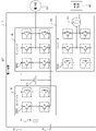
- the transformer 11 has a primary winding with one end connected to the positive input terminal 1 a and the other end connected to the negative input terminal 1 b, and a secondary winding connected to the converter 12 .
- the transformer 11 steps down the 25 kV single-phase AC power supplied from the current collector to 1520 V single-phase AC power, and supplies the stepped-down AC power to the converter 12 .
- the converter 12 has two sets of two switching elements SW1 connected in series. One set of switching elements SW1 and the other set of switching elements SW1 are connected in parallel with each other. One end of the secondary winding of the transformer 11 is connected to the connection point of the two switching elements SW1 of one set, and the secondary winding of the transformer 11 is connected to the connection point of the two switching elements SW1 of the other set. ends are connected.
- Each switching element SW1 has an IGBT (Insulated Gate Bipolar Transistor) and a free wheel diode whose anode is connected to the emitter terminal of the IGBT and whose cathode is connected to the collector terminal of the IGBT.
- a gate signal from a control unit (not shown) is supplied to the gate terminal of the IGBT of each switching element SW1 provided in the converter 12 to control on/off of the IGBT, that is, on/off of each switching element SW1.
- the converter 12 converts AC power supplied from the transformer 11 into DC power.
- the inverter 13 has three sets of two switching elements SW2 connected in series.
- the three sets of switching elements SW2 respectively correspond to the U-phase, V-phase and W-phase of the three-phase AC power.
- the switching element SW2 corresponding to the U phase, the switching element SW2 corresponding to the V phase, and the switching element SW2 corresponding to the W phase are connected in parallel with each other.
- Each switching element SW2 has an IGBT and a freewheeling diode, like the switching element SW1.
- a gate signal from a control unit (not shown) is supplied to the gate terminals of the IGBTs of the switching elements SW2 of the inverter 13 to control on/off of the IGBTs, that is, on/off of the switching elements SW2.
- the switching operation of each switching element SW2 causes the inverter 13 to convert the DC power into three-phase AC power and supply the three-phase AC power to the electric motor 61 .
- the switching elements SW1, SW2 and SW3 are repeatedly turned on and off, that is, perform switching operations and generate heat.
- the air conditioner 62 must be operated while the railway vehicle is stopped. Therefore, while the railway vehicle is stopped, inverter 13 is stopped and converter 12 and inverter 14 are in operation.
- the switching element SW2 does not generate heat, but the switching elements SW1 and SW3 repeatedly turn on and off and generate heat.
- the electronic device 1 cools the electronic components including the switching elements SW1, SW2, and SW3 by running wind when the railroad vehicle is running, and cools the electronic components including the switching elements SW1 and SW3 by natural convection when the railroad vehicle is stopped.
- the electronic device 1 is provided on the roof 100a of the vehicle 100.
- FIG. 3 which is a cross-sectional view taken along line III-III in FIG. 2
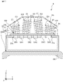
- the electronic device 1 is installed on a roof 100a and houses electronic components including switching elements SW1, SW2, and SW3. and a heat-conducting heat-receiving block 21 attached to the housing 20 with the electronic component attached to the first main surface 21a and the opening 20a of the housing 20 closed.
- the electronic device 1 further includes a heat transfer member 22 attached to the second main surface 21b of the heat receiving block 21 and transferring heat transferred from the electronic component via the heat receiving block 21 in a direction away from the second main surface 21b. , and fins 23 that are attached to the heat transfer member 22 and radiate heat transferred from the electronic component through the heat receiving block 21 and the heat transfer member 22 to the air.
- the electronic device 1 preferably includes a cover 30 that covers the heat transfer member 22 and the fins 23 and is attached to the housing 20 .
- the housing 20 is attached to the upper part of the roof 100a in the vertical direction.
- the housing 20 has such rigidity and strength that it does not deform even under the maximum expected vibration of the railway vehicle.
- the housing 20 is made of a metal member such as iron or aluminum.
- An opening 20a is formed in the upper portion of the housing 20 in the vertical direction.
- the heat receiving block 21 is attached to the housing 20 while closing the opening 20a.
- the heat receiving block 21 is a flat plate member made of a member having a high thermal conductivity, such as a metal member such as iron or aluminum, and attached to the outer surface of the housing 20 while closing the opening 20a.
- Electronic components that generate heat, specifically, switching elements SW1, SW2, and SW3 are attached to the first main surface 21a of the heat receiving block 21 .
- a heat transfer member 22 is attached to a second main surface 21b located opposite to the first main surface 21a. With the vehicle 100 positioned horizontally, the first main surface 21a and the second main surface 21b are horizontal.
- the heat transfer member 22 extends in a direction away from the second main surface 21b, and transfers heat transferred from the electronic component via the heat receiving block 21 in a direction away from the second main surface 21b.
- heat transfer member 22 has a heat pipe in which a refrigerant is sealed.
- the heat transfer member 22 has, as a heat pipe, a mother pipe 24a attached to the heat receiving block 21 and a branch pipe 24b attached to the mother pipe 24a and communicating with the mother pipe 24a.
- a refrigerant that exists in a gas-liquid two-phase state at room temperature is sealed inside the main pipe 24a and the branch pipe 24b.
- the coolant is, for example, water.
- FIG. 3 and FIG. 4 which is a cross-sectional view taken along line IV-IV in FIG. 3, a plurality of mother pipes 24a extending in the X-axis direction are arranged side by side in the Y-axis direction.
- eight mother pipes 24a extending in the X-axis direction are arranged side by side in the Y-axis direction.
- the mother pipe 24a is inserted into a groove formed in the second main surface 21b of the heat receiving block 21 and attached to the heat receiving block 21 by an attachment method such as bonding with an adhesive or soldering.
- the mother pipe 24a is a pipe made of a member having high thermal conductivity, such as a metal member such as iron or aluminum.
- a plurality of branch pipes 24b are attached to each mother pipe 24a.
- Each branch pipe 24b extends in the Z-axis direction.
- the branch pipe 24b is attached to the mother pipe 24a by an attachment method such as welding or soldering, and communicates with the mother pipe 24a.
- the branch pipe 24b is a pipe made of a member having high thermal conductivity, such as a metal member such as iron or aluminum.
- the length of the branch pipe 24b is set within the vehicle limit on the cross section perpendicular to the traveling direction of the vehicle 100, that is, on the YZ plane. Vehicle limits indicate the maximum dimensions of vehicle 100 .
- the fins 23 are attached to the heat transfer member 22 . Specifically, the fins 23 are attached to the heat transfer member 22 with the heat transfer member 22 inserted through the through holes formed in the fins 23 . The fins 23 attached to the heat transfer member 22 radiate the heat transferred from the electronic component through the heat receiving block 21 and the heat transfer member 22 to the surrounding air.
- the fins 23 are plate members made of a member having high thermal conductivity, such as a metal member such as iron or aluminum.
- the main surface of the fins 23 is preferably parallel to the X-axis. Since the running wind generated when the vehicle 100 is running flows in the X-axis direction, heat can be efficiently transmitted from the fins 23 to the running wind flowing between the fins 23 by making the main surfaces of the fins 23 parallel to the X-axis. can be done. As a result, it becomes possible to cool the electronic parts including the switching elements SW1, SW2, and SW3.
- the fins 23 are attached to the heat transfer member 22 with their main surfaces inclined with respect to the horizontal plane when the vehicle 100 is horizontally positioned. Since the main surfaces of the fins 23 are inclined with respect to the horizontal plane, the air warmed by heat transfer from the fins 23 moves vertically upward along the fins 23 . Due to the air flow described above, air flows in from the outside, and heat is transferred from the fins 23 to the inflowing air. Since the main surfaces of the fins 23 are tilted with respect to the horizontal plane, the above-described air flow is generated, and the electronic components including the switching elements SW1, SW2, and SW3 can be cooled.
- the fins 23 located at both ends in the Y-axis direction are attached to the heat transfer member 22 not horizontally, but in such a direction that the position in the vertical direction increases toward the center in the Y-axis direction.
- the fins 23 located at the center in the Y-axis direction are positioned vertically at one end 231 near the center of the vehicle 100 among both ends in the Y-axis direction when the vehicle 100 is horizontally positioned. is attached to the heat transfer member 22, that is, the branch pipe 24b in a direction lower than the other end 232 in the vertical direction.
- the fin 23 located in the center in the Y-axis direction is attached to the heat transfer member 22 not horizontally, but in such a direction that the position in the vertical direction increases toward the end in the Y-axis direction.
- the cover 30 is attached to the housing 20 while covering the heat receiving block 21 , the heat transfer member 22 and the fins 23 .
- the surface of the cover 30 along the X-axis direction is provided with a plurality of ventilators for allowing external air to flow into the cover 30 and for causing the air that has flowed near the heat transfer member 22 and the fins 23 to flow out of the cover 30.
- a hole 30a is formed.
- the surface of the cover 30 that intersects the X-axis direction allows external air to flow into the inside of the cover 30, and the air that has flowed near the heat transfer member 22 and the fins 23 is directed to the outside of the cover 30.
- a plurality of ventilation holes 30b are formed to allow the air to flow out.
- the cooling of the electronic components included in the electronic device 1 having the above configuration will be described below.
- Heat generated by at least one of switching elements SW1, SW2, and SW3 is transferred to the refrigerant via heat receiving block 21 and main pipe 24a.
- the refrigerant vaporizes.
- the vaporized refrigerant moves in the Z-axis positive direction inside the branch pipe 24b.
- the refrigerant is cooled and liquefied by transferring heat to the air around the heat transfer member 22 through the branch pipes 24b and the fins 23 while moving in the positive direction of the Z axis.
- the liquefied refrigerant moves along the inner wall of the branch pipe 24b in the negative direction of the Z axis.
- traveling wind is generated that flows in the negative direction of the X axis as indicated by arrow AR1 in FIG.
- arrow AR1 in FIG. 5
- Running wind passes between the fins 23 .
- heat is transferred from the fins 23 to the running wind to cool the switching elements SW1, SW2, and SW3.
- the density of the air warmed by heat transfer from the fins 23 is lower than the density of the distant room temperature air, for example, the air outside the cover 30 .
- the buoyant force caused by the difference in air density exceeds the viscous force of the air, air flows around the fins 23 .
- the ratio of buoyant force to viscous force in natural convection is represented by the Grashof number Gr in the following equation (1). The larger the Grashof number Gr, the more likely natural convection occurs.
- g indicates gravitational acceleration (unit: m/s 2 ).
- ⁇ indicates the body expansion coefficient (unit: 1/K) of fluid, specifically air.
- ⁇ T indicates a representative temperature difference, more specifically, a temperature difference between the heating element and the fluid, that is, a temperature difference (unit: K) between the temperature of the fins 23 and the air.
- L represents a representative length, specifically, the length of the heating element along the air flow, that is, the length of the fins 23 along the air flow.
- ⁇ represents the dynamic viscosity coefficient of fluid, specifically air (unit: m 2 /s).
- the fins 23 are attached to the heat transfer member 22 in such a direction that the main surface is inclined with respect to the horizontal plane. For this reason, the value of the representative length L is increased and the Grashof number Gr is increased as compared with the conventional electronic device in which the fins are provided horizontally. In other words, natural convection is more likely to occur than in conventional electronic devices with horizontal fins. As shown in FIG. 7, the air that has moved vertically upward due to the heat transferred from the vertically lower fins 23 or branch pipes 24b located vertically downwards travels along the fins 23 that are inclined with respect to the horizontal plane. Further move upward in the vertical direction.
- the air inside the cover 30 is warmed by heat transfer from the fins 23 and moves vertically upward along the fins 23, as indicated by the arrow AR2 in FIG.
- the air that has moved upward in the vertical direction flows out of the cover 30 through ventilation holes 30 a formed in the vertical upper portion of the cover 30 .
- the air outside the cover 30 flows into the inside of the cover 30 through the ventilation holes 30a formed in the side surface of the cover 30, as indicated by an arrow AR3. do.
- the air outside the cover 30 flows into the cover 30 through the ventilation holes 30b (not shown in FIG. 8). In FIG. 8, only part of the air flow is shown to avoid complicating the drawing.
- the air that has flowed into the cover 30 is warmed by heat transfer from the fins 23, moves vertically upward along the fins 23, and flows out of the cover 30 through the ventilation holes 30a. . Since the fins 23 are attached to the heat transfer member 22 in such a direction that the main surfaces are inclined with respect to the horizontal plane, air flows vertically upward along the fins 23 . In this manner, by utilizing natural convection, switching elements SW1, SW2, and SW3 can be cooled even when vehicle 100 is stopped.
- the value of the representative length L in the above equation (1) increases and the Grashof number Gr increases. Cooling performance by natural convection is improved. However, if the angle between the main surface of the fins 23 and the horizontal plane is increased while the vehicle 100 is positioned horizontally, the number of fins 23 that can be installed within the vehicle limits is reduced. As the number of fins 23 decreases, the cooling performance decreases due to the decrease in the heat radiation area. 23 is preferably determined according to the space in which it can be installed.
- the electronic device 1 includes the fins 23 attached to the heat transfer member 22 such that the main surface is inclined with respect to the horizontal plane when the vehicle 100 is positioned horizontally.
- the air warmed by heat transfer from the fins 23 moves vertically upward along the fins 23 .
- the fins 23 are inclined with respect to the horizontal plane, an air flow is generated that moves vertically upward along the fins 23 , and the electronic device 1 uses natural convection to perform switching even when the vehicle 100 is stopped. It becomes possible to cool the electronic parts including the elements SW1, SW2, and SW3.
- Embodiment 2 The installation position of the electronic device 1 and the arrangement of the heat transfer member 22 and the fins 23 are not limited to the above examples, and are arbitrary as long as the electronic components can be cooled using natural convection.
- an electronic device 2 provided in a housing portion 100b formed on a roof 100a of a vehicle 100 and including a heat transfer member 22 extending in a direction forming an acute angle with respect to a second main surface 21b will be described in Embodiment 2. .
- the roof 100a of the vehicle 100 is formed with a housing portion 100b, which is a concave portion with an open upper portion in the vertical direction. Specifically, the opening surface of the housing portion 100b is located on the same plane as the upper end of the roof 100a of the vehicle 100 in the vertical direction.
- the housing portion 100 b houses the housing 20 of the electronic device 2 . Specifically, the bottom surface of the housing 20 is attached to the bottom surface of the housing portion 100b.
- At least part of the heat transfer member 22 and at least part of the fins 23 are preferably positioned vertically above the upper end of the roof 100a in the vertical direction in order to improve the cooling performance.
- the components of the electronic device 2 are the same as those of the electronic device 1 according to Embodiment 1, but the arrangement of the heat transfer member 22 and the fins 23 is different from that of the electronic device 1 .
- the heat transfer member 22 extends in a direction forming an acute angle with respect to the second main surface 21b.
- the heat transfer member 22 includes a mother pipe 24a similar to that of the first embodiment, and a branch pipe 24b attached to the mother pipe 24a in a direction extending in a direction forming an acute angle with respect to the second main surface 21b. have.
- the branch pipe 24b is separated from the second main surface 21b and extends in the direction from the center in the width direction toward the end.
- mother pipes 24a are attached to the second main surface 21b in the Y-axis direction.
- the branch pipes 24b attached to the four mother pipes 24a positioned on the Y-axis negative direction side of the Y-axis direction center of the second main surface 21b are separated from the second main surface 21b and extend in the Y-axis negative direction. Extend.
- the branch pipes 24b attached to the four mother pipes 24a located on the Y-axis positive direction side of the Y-axis direction center of the second main surface 21b are separated from the second main surface 21b and directed in the Y-axis positive direction. direction.
- the fins 23 are attached to the heat transfer member 22 so that the main surface is inclined with respect to the horizontal plane when the vehicle 100 is horizontally positioned. Specifically, the fins 23 are attached to the heat transfer member 22 so that the main surfaces thereof are perpendicular to the extending direction of the branch pipes 24b. Since the heat transfer member 22 extends in a direction forming an acute angle with respect to the second main surface 21b, the main surfaces of the fins 23 orthogonal to the extending direction of the branch pipes 24b are inclined with respect to the second main surface 21b. Since the second main surface 21b is horizontal when the vehicle 100 is positioned horizontally, the main surfaces of the fins 23 are inclined with respect to the horizontal plane.
- the vertical position of one end 231 near the center of the vehicle 100 is higher than the vertical position of the other end 232 .
- the running wind passes through the fins 23 as in the first embodiment, and heat is transferred from the fins 23 to the running wind to cool the switching elements SW1, SW2, and SW3.
- the air that has flowed into the cover 30 is warmed by heat transfer from the fins 23, moves vertically upward along the fins 23, and flows out of the cover 30 through the ventilation holes 30a. . Since the fins 23 are attached to the branch pipes 24b in a direction perpendicular to the extension direction of the branch pipes 24b extending in a direction forming an acute angle with respect to the second main surface 21b, the fins 23 move vertically upward along the fins 23. air flow is generated. In this manner, by utilizing natural convection, switching elements SW1, SW2, and SW3 can be cooled even when vehicle 100 is stopped.
- the value of the representative length L in the above equation (1) becomes larger and the Grashof number Gr becomes larger, so that the cooling performance by natural convection is improved. get higher
- the number of fins 23 that can be installed within the vehicle limits becomes smaller. As the number of fins 23 decreases, the cooling performance decreases due to the decrease in the heat radiation area. It is preferably determined according to available space.
- the acute angle formed by the extending direction of the branch pipe 24b and the second main surface 21b is preferably 75 degrees or more.
- the acute angle between the extension direction of the branch pipe 24b and the second main surface 21b is preferably 75 degrees or more and 85 degrees or less.
- the electronic device 2 includes the heat transfer member 22 extending in a direction forming an acute angle with respect to the second main surface 21b, and the heat transfer member 22 extending in a direction and a fin 23 attached to the heat transfer member 22 at.
- the air warmed by heat transfer from the fins 23 moves vertically upward along the fins 23 .
- the fins 23 are inclined with respect to the horizontal plane, an air flow is generated that moves vertically upward along the fins 23 , and the electronic device 1 uses natural convection to perform switching even when the vehicle 100 is stopped. It becomes possible to cool the electronic parts including the elements SW1, SW2, and SW3.
- the present disclosure is not limited to the above embodiments.
- the above embodiments can be combined arbitrarily.
- the inverter 14 can supply power not only to the air conditioner 62 but also to any load device that is in operation when the vehicle 100 is stopped.
- the inverter 14 can supply power to a lighting device, a door opening/closing device of the vehicle 100, and the like.
- the shape of the housing 20 is arbitrary as long as it accommodates electronic components including the switching elements SW1, SW2, and SW3 inside and can be attached to the roof 100a.
- the vertical upper surface of the housing 25 included in the electronic device 3 shown in FIG. 12 is tilted with respect to the horizontal plane when the vehicle 100 is positioned horizontally.
- the opening surface of the opening 25a is inclined with respect to the horizontal plane.
- the second main surface 21b of the heat receiving block 21 that closes the opening 25a that is tilted with respect to the horizontal plane is tilted with respect to the horizontal plane when the vehicle 100 is positioned horizontally.
- the heat transfer member 22 should just extend in the direction orthogonal to the 2nd main surface 21b.
- the heat transfer member 22 extends in a direction forming an acute angle with respect to the horizontal plane.
- the branch pipe 24b is attached to the mother pipe 24a in a direction extending in a direction orthogonal to the second main surface 21b.
- the fins 23 may be attached to the heat transfer member 22 so that the main surface is perpendicular to the direction in which the heat transfer member 22 extends.
- the fins 23 may be attached to the branch pipe 24b so that the main surfaces thereof are perpendicular to the extending direction of the branch pipe 24b. Since the heat transfer member 22 extends in a direction forming an acute angle with respect to the horizontal plane, the main surfaces of the fins 23 are inclined with respect to the horizontal plane. As a result, while the vehicle 100 is stopped, an air flow vertically upward along the fins 23 is generated, and the electronic components including the switching elements SW1, SW2, SW3 can be cooled by natural convection.
- the heat-receiving block 21 may be a plate-like member having a curved surface protruding away from the housing 20 .
- the heat transfer member 22 may be extended in a direction forming an acute angle with respect to the horizontal plane while the vehicle 100 is positioned horizontally.
- the heat-receiving block 21 may be formed of a single plate-like member, or may be formed by combining a plurality of plate-like members.
- the electronic components attached to the heat receiving block 21 are not limited to the switching elements SW1, SW2, and SW3, and may be arbitrary electronic components housed inside the housings 20 and 25, such as thyristors and diodes.
- the arrangement of the heat transfer member 22, specifically, the arrangement of the branch pipe 24b is not limited to the above example, and is arbitrary as long as it is possible to cool the electronic components using natural convection.
- the branch pipe 24b provided at a position near the end of the vehicle 100 in the Y-axis direction is separated from the second main surface 21b and is located at the end of the vehicle 100 in the Y-axis direction. extending toward the part.
- Branch pipe 24b provided near the center in the Y-axis direction of vehicle 100 is separated from second main surface 21b and extends in a direction toward the center in the Y-axis direction.
- the two branch pipes 24b near the end of the vehicle 100 in the negative Y-axis direction are separated from the second main surface 21b and extend in the negative Y-axis direction.
- the two branch pipes 24b near the end of the vehicle 100 in the positive Y-axis direction are separated from the second main surface 21b and extend in the positive Y-axis direction.
- the two branch pipes 24b positioned on the Y-axis negative direction side are separated from the second main surface 21b and extend in the Y-axis positive direction.
- the two branch pipes 24b positioned in the positive Y-axis direction are separated from the second main surface 21b and extend in the negative Y-axis direction.
- the number, shape, and arrangement position of the fins 23 are not limited to the above examples, and are arbitrary.
- the fins 23 may be plate-like members having curved surfaces.
- each fin 23 may have a different shape.
- a plurality of fins 23 may be arranged in the Z-axis direction. In this case, the vertically lower fins 23 may be attached to all the heat transfer members 22 .
- the shape of the cover 30 is arbitrary as long as it covers the heat transfer member 22 and the fins 23 and allows air to flow inside.
- the cover 30 may have a curved top surface in the vertical direction.
- the cover 30 may have a flat top surface in the vertical direction.
- the cover 30 preferably has a shape that maximizes internal space within the vehicle limits.
Landscapes
- Engineering & Computer Science (AREA)
- Microelectronics & Electronic Packaging (AREA)
- Physics & Mathematics (AREA)
- Thermal Sciences (AREA)
- Automation & Control Theory (AREA)
- Transportation (AREA)
- Mechanical Engineering (AREA)
- Cooling Or The Like Of Electrical Apparatus (AREA)
Priority Applications (5)
| Application Number | Priority Date | Filing Date | Title |
|---|---|---|---|
| PCT/JP2021/022795 WO2022264301A1 (ja) | 2021-06-16 | 2021-06-16 | 電子機器 |
| PCT/JP2021/047825 WO2022264460A1 (ja) | 2021-06-16 | 2021-12-23 | 電子機器 |
| JP2023529450A JP7408017B2 (ja) | 2021-06-16 | 2021-12-23 | 電子機器 |
| US18/555,891 US20240206132A1 (en) | 2021-06-16 | 2021-12-23 | Electronic device |
| DE112021007818.6T DE112021007818T5 (de) | 2021-06-16 | 2021-12-23 | Elektronische Einrichtung |
Applications Claiming Priority (1)
| Application Number | Priority Date | Filing Date | Title |
|---|---|---|---|
| PCT/JP2021/022795 WO2022264301A1 (ja) | 2021-06-16 | 2021-06-16 | 電子機器 |
Publications (1)
| Publication Number | Publication Date |
|---|---|
| WO2022264301A1 true WO2022264301A1 (ja) | 2022-12-22 |
Family
ID=84525986
Family Applications (2)
| Application Number | Title | Priority Date | Filing Date |
|---|---|---|---|
| PCT/JP2021/022795 Ceased WO2022264301A1 (ja) | 2021-06-16 | 2021-06-16 | 電子機器 |
| PCT/JP2021/047825 Ceased WO2022264460A1 (ja) | 2021-06-16 | 2021-12-23 | 電子機器 |
Family Applications After (1)
| Application Number | Title | Priority Date | Filing Date |
|---|---|---|---|
| PCT/JP2021/047825 Ceased WO2022264460A1 (ja) | 2021-06-16 | 2021-12-23 | 電子機器 |
Country Status (4)
| Country | Link |
|---|---|
| US (1) | US20240206132A1 (https=) |
| JP (1) | JP7408017B2 (https=) |
| DE (1) | DE112021007818T5 (https=) |
| WO (2) | WO2022264301A1 (https=) |
Families Citing this family (2)
| Publication number | Priority date | Publication date | Assignee | Title |
|---|---|---|---|---|
| WO2023144914A1 (ja) * | 2022-01-26 | 2023-08-03 | 三菱電機株式会社 | 電子機器 |
| JPWO2025224805A1 (https=) * | 2024-04-22 | 2025-10-30 |
Citations (3)
| Publication number | Priority date | Publication date | Assignee | Title |
|---|---|---|---|---|
| JPH01139019U (https=) * | 1988-03-18 | 1989-09-22 | ||
| JP2000092819A (ja) * | 1998-09-10 | 2000-03-31 | Toshiba Corp | 半導体冷却装置 |
| JP2016201446A (ja) * | 2015-04-09 | 2016-12-01 | 三菱電機株式会社 | 車両用変圧器 |
Family Cites Families (13)
| Publication number | Priority date | Publication date | Assignee | Title |
|---|---|---|---|---|
| JPS63174501A (ja) * | 1987-01-14 | 1988-07-19 | Toshiba Corp | 電気車の制御装置 |
| JP3094780B2 (ja) * | 1994-04-05 | 2000-10-03 | 株式会社日立製作所 | 電子装置 |
| JP2000161880A (ja) * | 1998-11-26 | 2000-06-16 | Toshiba Corp | ヒートパイプ式冷却器 |
| JP2001118976A (ja) * | 1999-10-20 | 2001-04-27 | Hitachi Ltd | 電子部品の冷却装置 |
| JP2003079164A (ja) * | 2001-08-31 | 2003-03-14 | Toshiba Transport Eng Inc | 電力変換装置 |
| JP5466073B2 (ja) * | 2010-04-23 | 2014-04-09 | 株式会社日立製作所 | 電力変換装置および鉄道車両 |
| JP6097648B2 (ja) * | 2013-07-10 | 2017-03-15 | 株式会社日立製作所 | 電力変換装置及びこれを搭載した鉄道車両 |
| FR3029485B1 (fr) * | 2014-12-03 | 2018-03-16 | Alstom Transport Technologies | Dispositif aeraulique de refroidissement d'un element d'un vehicule ferroviaire et vehicule ferroviaire correspondant |
| US20160255746A1 (en) * | 2015-02-27 | 2016-09-01 | Laird Technologies, Inc. | Heat sinks including heat pipes and related methods |
| CN105845648A (zh) * | 2016-05-10 | 2016-08-10 | 成都中微电微波技术有限公司 | 一种微电子器件树形散热器 |
| JP7045457B2 (ja) * | 2017-12-08 | 2022-03-31 | ケーエムダブリュ・インコーポレーテッド | 電装素子の放熱装置 |
| JP2021022795A (ja) | 2019-07-26 | 2021-02-18 | キヤノン株式会社 | 画像読取装置 |
| KR20210061682A (ko) * | 2019-11-20 | 2021-05-28 | 주식회사 브이씨텍 | 하이브리드 냉각 구조를 갖는 철도 차량용 인버터 스택 |
-
2021
- 2021-06-16 WO PCT/JP2021/022795 patent/WO2022264301A1/ja not_active Ceased
- 2021-12-23 US US18/555,891 patent/US20240206132A1/en active Pending
- 2021-12-23 WO PCT/JP2021/047825 patent/WO2022264460A1/ja not_active Ceased
- 2021-12-23 DE DE112021007818.6T patent/DE112021007818T5/de active Granted
- 2021-12-23 JP JP2023529450A patent/JP7408017B2/ja active Active
Patent Citations (3)
| Publication number | Priority date | Publication date | Assignee | Title |
|---|---|---|---|---|
| JPH01139019U (https=) * | 1988-03-18 | 1989-09-22 | ||
| JP2000092819A (ja) * | 1998-09-10 | 2000-03-31 | Toshiba Corp | 半導体冷却装置 |
| JP2016201446A (ja) * | 2015-04-09 | 2016-12-01 | 三菱電機株式会社 | 車両用変圧器 |
Also Published As
| Publication number | Publication date |
|---|---|
| JP7408017B2 (ja) | 2024-01-04 |
| US20240206132A1 (en) | 2024-06-20 |
| WO2022264460A1 (ja) | 2022-12-22 |
| JPWO2022264460A1 (https=) | 2022-12-22 |
| DE112021007818T5 (de) | 2024-03-28 |
Similar Documents
| Publication | Publication Date | Title |
|---|---|---|
| CA2688583C (en) | Electric power converting apparatus | |
| JP3469475B2 (ja) | 鉄道車両用半導体冷却装置 | |
| JP6169187B2 (ja) | 電力変換装置 | |
| CN113226833B (zh) | 用于感应功率传输垫的固定部件 | |
| CN218788733U (zh) | 功率转换装置 | |
| JP7408017B2 (ja) | 電子機器 | |
| JP2012070525A (ja) | 車両用の電源装置 | |
| WO2019021532A1 (ja) | 電力変換装置 | |
| JP6081091B2 (ja) | 鉄道車両用制御装置 | |
| US11818868B2 (en) | Cooling device and power conversion device | |
| JP7520259B2 (ja) | 電子機器 | |
| GB2523625A (en) | Power conversion device and railway vehicle equipped with the same | |
| JP2005123459A (ja) | 半導体冷却装置 | |
| JP7408031B2 (ja) | 電子機器 | |
| CN106169835A (zh) | 车辆用驱动装置 | |
| JP7665100B2 (ja) | 電子機器 | |
| JP7504294B2 (ja) | 電子機器 | |
| JP2020171196A (ja) | 鉄道車両の電力変換装置 | |
| JP4421132B2 (ja) | 鉄道車両用電力変換装置 | |
| HK40112516A (en) | Electronic device | |
| JP2017200305A (ja) | 鉄道車両の電力変換装置 | |
| JP2011097673A (ja) | 電源装置 | |
| WO2023199442A1 (ja) | 電力変換装置 | |
| JP2003273299A (ja) | 車両用半導体冷却装置 | |
| JP2022090825A (ja) | 電力変換装置 |
Legal Events
| Date | Code | Title | Description |
|---|---|---|---|
| 121 | Ep: the epo has been informed by wipo that ep was designated in this application |
Ref document number: 21945979 Country of ref document: EP Kind code of ref document: A1 |
|
| NENP | Non-entry into the national phase |
Ref country code: DE |
|
| 122 | Ep: pct application non-entry in european phase |
Ref document number: 21945979 Country of ref document: EP Kind code of ref document: A1 |
|
| NENP | Non-entry into the national phase |
Ref country code: JP |