WO2022264271A1 - 温度推定システムおよび温度推定方法 - Google Patents
温度推定システムおよび温度推定方法 Download PDFInfo
- Publication number
- WO2022264271A1 WO2022264271A1 PCT/JP2021/022707 JP2021022707W WO2022264271A1 WO 2022264271 A1 WO2022264271 A1 WO 2022264271A1 JP 2021022707 W JP2021022707 W JP 2021022707W WO 2022264271 A1 WO2022264271 A1 WO 2022264271A1
- Authority
- WO
- WIPO (PCT)
- Prior art keywords
- temperature
- subject
- temperature sensor
- heart rate
- skin
- Prior art date
- Legal status (The legal status is an assumption and is not a legal conclusion. Google has not performed a legal analysis and makes no representation as to the accuracy of the status listed.)
- Ceased
Links
Images














Classifications
-
- G—PHYSICS
- G01—MEASURING; TESTING
- G01K—MEASURING TEMPERATURE; MEASURING QUANTITY OF HEAT; THERMALLY-SENSITIVE ELEMENTS NOT OTHERWISE PROVIDED FOR
- G01K13/00—Thermometers specially adapted for specific purposes
- G01K13/20—Clinical contact thermometers for use with humans or animals
-
- A—HUMAN NECESSITIES
- A61—MEDICAL OR VETERINARY SCIENCE; HYGIENE
- A61B—DIAGNOSIS; SURGERY; IDENTIFICATION
- A61B5/00—Measuring for diagnostic purposes; Identification of persons
- A61B5/01—Measuring temperature of body parts ; Diagnostic temperature sensing, e.g. for malignant or inflamed tissue
-
- A—HUMAN NECESSITIES
- A61—MEDICAL OR VETERINARY SCIENCE; HYGIENE
- A61B—DIAGNOSIS; SURGERY; IDENTIFICATION
- A61B5/00—Measuring for diagnostic purposes; Identification of persons
- A61B5/02—Detecting, measuring or recording for evaluating the cardiovascular system, e.g. pulse, heart rate, blood pressure or blood flow
- A61B5/024—Measuring pulse rate or heart rate
- A61B5/02416—Measuring pulse rate or heart rate using photoplethysmograph signals, e.g. generated by infrared radiation
-
- A—HUMAN NECESSITIES
- A61—MEDICAL OR VETERINARY SCIENCE; HYGIENE
- A61B—DIAGNOSIS; SURGERY; IDENTIFICATION
- A61B5/00—Measuring for diagnostic purposes; Identification of persons
- A61B5/02—Detecting, measuring or recording for evaluating the cardiovascular system, e.g. pulse, heart rate, blood pressure or blood flow
- A61B5/024—Measuring pulse rate or heart rate
- A61B5/02444—Details of sensor
-
- A—HUMAN NECESSITIES
- A61—MEDICAL OR VETERINARY SCIENCE; HYGIENE
- A61B—DIAGNOSIS; SURGERY; IDENTIFICATION
- A61B5/00—Measuring for diagnostic purposes; Identification of persons
- A61B5/68—Arrangements of detecting, measuring or recording means, e.g. sensors, in relation to patient
- A61B5/6801—Arrangements of detecting, measuring or recording means, e.g. sensors, in relation to patient specially adapted to be attached to or worn on the body surface
- A61B5/6802—Sensor mounted on worn items
- A61B5/681—Wristwatch-type devices
-
- G—PHYSICS
- G01—MEASURING; TESTING
- G01K—MEASURING TEMPERATURE; MEASURING QUANTITY OF HEAT; THERMALLY-SENSITIVE ELEMENTS NOT OTHERWISE PROVIDED FOR
- G01K7/00—Measuring temperature based on the use of electric or magnetic elements directly sensitive to heat ; Power supply therefor, e.g. using thermoelectric elements
- G01K7/42—Circuits effecting compensation of thermal inertia; Circuits for predicting the stationary value of a temperature
- G01K7/427—Temperature calculation based on spatial modeling, e.g. spatial inter- or extrapolation
Definitions
- the present invention relates to a temperature estimation system and a temperature estimation method for noninvasively and accurately estimating the internal temperature of a subject such as a living body.
- Core body temperature is known as an index for measuring circadian rhythms.
- the most common methods of measuring core body temperature are methods such as inserting a thermometer into the rectum or measuring the temperature of the eardrum with the ear closed, and measuring core body temperature during daily activities or during sleep. It was a very stressful method.
- Patent Document 1 As a technique for non-invasively measuring the core body temperature of a living body, there is a technique for estimating the core body temperature by replacing the heat flow with a one-dimensional equivalent circuit model (Patent Document 1, Non-Patent Document 1).
- Patent Document 1 and Non-Patent Document 1 estimate the core body temperature T cbt of the living body 100 using a thermal equivalent circuit model of the living body 100 and the sensor 101 as shown in FIG. 26 .
- the core body temperature T cbt of the living body 100 is determined by the temperature T skin on the surface side of the sensor 101 in contact with the living body 100 and the surface opposite to the surface in contact with the living body 100. It can be estimated using the equation (1) from the temperature T top of the upper surface of the sensor 101 on the side.
- T cbt T skin + ⁇ H skin (1)
- H skin is the heat flux on the skin surface of the living body 100 and is represented by Equation (2).
- H skin (T skin ⁇ T top )/R skin (2)
- ⁇ is a proportional coefficient related to the thermal resistance R body of the living body 100
- R skin is the thermal resistance of the sensor 101 .
- Patent Literature 1 and Non-Patent Literature 1 the flow of heat transported from the living body 100 through the sensor 101 to the outside air is assumed to be steady.
- the living body 100 runs or suddenly moves from a warm place to a cold place, there is a problem that a transitional error occurs in the estimation of the core body temperature T cbt .
- the thermal resistance R body of the living body 100 is assumed to be constant regardless of time, and the proportionality coefficient ⁇ is also assumed to be constant.
- the blood flow state near the skin of the living body 100 also changes depending on the posture and movement of the living body 100 . For this reason, the thermal resistance R body is not constant and changes every moment.
- the difference between the true core body temperature T ref and the estimated core body temperature T cbt is when the temperature T top of the upper surface of the sensor 101 and the temperature T skin of the skin surface of the person are in the steady state when the wind hits the person. This is due to the fact that there is a difference in the time it takes for the blood to settle down, and that the blood flow changes depending on the person's posture. In addition, in a state where the wind is constantly changing, it cannot be expected that the temperature will settle down to a steady state even if the person is at rest and there is no change in the blood flow. Further, in the conventional method, it is necessary to calibrate the proportionality coefficient ⁇ using another sensor such as an eardrum thermometer each time the measurement is performed, even in a state where the heat flow can be assumed to be stationary.
- the temperature distribution inside an object can generally be described by the following heat conduction equation.
- T is temperature
- k thermal conductivity
- c heat capacity
- ⁇ density
- Q internal heat generation
- Q is a term generated during exercise or the like.
- .DELTA. is the operator of the second derivative with respect to space, which is .differential.2/.differential.x2 + .differential.2/.differential.y2 + .differential.2/ .differential.z2 in a three - dimensional orthogonal coordinate system.
- Values k, ⁇ , and c related to thermal characteristics vary from time to time due to various factors such as the amount of water in human skin, dilation and contraction of capillaries due to human activity, sweating, and dilation and contraction of blood vessels due to blood pressure that changes with human posture. It changes moment by moment. Since ⁇ in Equation (1) is a proportionality coefficient corresponding to k/( ⁇ c), the proportionality coefficient ⁇ also changes from moment to moment.
- Patent Document 1 and Non-Patent Document 1 use a one-dimensional thermal equivalent circuit model.
- the equivalent circuit model no longer holds. In other words, it is possible to estimate the internal temperature of an object with a sufficiently stable heat flow, but it is not possible to estimate the internal temperature of a non-stationary dynamic object such as a living body. Therefore, it is necessary to obtain the internal temperature (core body temperature T cbt ) or the proportionality coefficient ⁇ in some way taking into consideration the equation (3).
- the present invention has been made to solve the above-described problems, and is a temperature estimation system and a temperature estimation system capable of reducing an estimation error of the internal temperature of a subject such as a living body without calibrating a proportionality coefficient each time measurement is performed.
- the purpose is to provide an estimation method.
- a temperature estimation system of the present invention comprises a heat insulating material, a first temperature sensor provided on a surface of the heat insulating material facing a subject and configured to measure the temperature of the surface of the subject, a second temperature sensor configured to measure the temperature inside the heat insulating material directly above the temperature sensor of, and a temperature of the surface of the subject at a position remote from the first temperature sensor and a learner configured to estimate a proportional coefficient related to the thermal resistance of the subject based on the measurement results of the first, second, and third temperature sensors and a temperature calculator configured to calculate the internal temperature of the subject based on the measurement results of the first and second temperature sensors and the proportional coefficient.
- one configuration example of the temperature estimation system of the present invention further includes a heart rate measuring unit configured to measure the heart rate of the subject, and the learning device comprises the first, second, and third The proportionality coefficient is estimated based on the measurement result of the temperature sensor and the measurement result of the heart rate measuring unit.
- the temperature estimation system of the present invention includes a heat insulating material, a first temperature sensor provided on a surface of the heat insulating material facing a subject and configured to measure the temperature of the surface of the subject, and A second temperature sensor configured to measure the temperature inside the heat insulating material immediately above the first temperature sensor, and measuring the temperature of the surface of the subject at a position away from the first temperature sensor and a learner configured to estimate the internal temperature of the subject based on the measurement results of the first, second, and third temperature sensors.
- one configuration example of the temperature estimation system of the present invention further includes a heart rate measuring unit configured to measure the heart rate of the subject, and the learning device comprises the first, second, and third The internal temperature of the subject is estimated based on the measurement result of the temperature sensor and the measurement result of the heart rate measuring unit.
- one configuration example of the temperature estimation system of the present invention includes a plurality of the learners prepared in advance to correspond to the state of the subject or the environment around the subject, and the first temperature sensor Based on at least one of the measurement result and the measurement result of the second temperature sensor, a learner corresponding to the state of the subject or the environment surrounding the subject is selected from the plurality of learners for the estimation. It is characterized by further comprising a selection unit configured to select for.
- one configuration example of the temperature estimation system of the present invention includes a plurality of the learners prepared in advance to correspond to the state of the subject or the environment around the subject, and the first temperature sensor Based on at least one of the measurement result, the measurement result of the second temperature sensor, and the measurement result of the heart rate measurement unit, the state of the subject or the surroundings of the subject is selected from among the plurality of learners. It is characterized by further comprising a selection unit configured to select a learner corresponding to the environment for the estimation.
- the temperature estimation method of the present invention includes a first step of measuring the temperature of the surface of the subject with a first temperature sensor provided on a surface of a heat insulating material facing the subject; A second step of measuring the temperature inside the heat insulating material directly above with a second temperature sensor, and measuring the temperature of the surface of the subject at a position away from the first temperature sensor with a third temperature sensor a third step of measuring; and a fourth step of estimating a proportional coefficient related to the thermal resistance of the subject based on the measurement results of the first, second, and third steps with a learned learner; and a fifth step of calculating the internal temperature of the subject based on the measurement results of the first and second steps and the proportional coefficient.
- one configuration example of the temperature estimation method of the present invention further includes a sixth step of measuring the heart rate of the subject, wherein the fourth step is the same as the first, second, and third steps.
- the method is characterized by including a step of estimating the proportional coefficient based on the measurement result and the measurement result of the sixth step.
- the internal temperature of the object can be estimated with high accuracy without calibrating the proportional coefficient each time measurement is performed.
- the internal temperature of the object can be estimated with high accuracy without calibrating the proportionality coefficient each time measurement is performed.
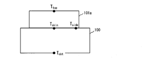
- FIG. 1 is a schematic diagram in which sensors are arranged on the surface of a living body.
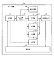
- FIG. 2 is a block diagram showing the configuration of the temperature estimation system according to the first embodiment of the invention.
- 3 is a plan view showing the surface of the housing of the temperature measuring unit of FIG. 2.
- FIG. 4 is a block diagram showing another example of the temperature measuring section according to the first embodiment of the present invention.
- 5 is a plan view showing the surface of the housing of the temperature measuring unit of FIG. 4.
- FIG. FIG. 6 is a block diagram showing another example of the temperature measuring section according to the first embodiment of the present invention.
- FIG. 7 is a block diagram showing another example of the temperature measuring section according to the first embodiment of the present invention.
- FIG. 1 is a schematic diagram in which sensors are arranged on the surface of a living body.
- FIG. 2 is a block diagram showing the configuration of the temperature estimation system according to the first embodiment of the invention.
- 3 is a plan view showing the surface of the housing of the temperature measuring unit of
- FIG. 8 is a block diagram showing another example of the temperature measuring section according to the first embodiment of the present invention.
- 9 is a plan view showing the surface of the housing of the temperature measuring unit of FIG. 8.
- FIG. 10 is a block diagram showing another example of the temperature measurement section according to the first embodiment of the present invention.
- FIG. 11 is a block diagram showing another example of the temperature measuring section according to the first embodiment of the present invention.
- 12 is a plan view showing the surface of the housing of the temperature measuring unit of FIG. 11.
- FIG. 13 is a plan view showing another arrangement example of the temperature sensors according to the first embodiment of the present invention.
- FIG. 14 is a plan view showing another arrangement example of the temperature sensors according to the first embodiment of the present invention.
- FIG. 15 is a block diagram showing another example of the temperature measurement section according to the first embodiment of the present invention
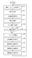
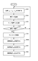
- FIG. 16 is a flow chart explaining the operation of the temperature estimation system according to the first example of the present invention.
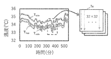
- FIG. 17 is a diagram for explaining a tensor generation method according to the first embodiment of the present invention.
- FIG. 18 is a flow chart explaining another operation of the temperature estimation system according to the first example of the present invention.
- FIG. 19A is a diagram showing an example of core body temperature estimated by the method of the first embodiment of the present invention.
- FIG. 19B is a diagram showing an example of true core body temperature measured by a tympanic thermometer.
- FIG. 20 is a block diagram showing the configuration of the server device of the temperature estimation system according to the second embodiment of the present invention.
- FIG. 20 is a block diagram showing the configuration of the server device of the temperature estimation system according to the second embodiment of the present invention.
- FIG. 21 is a flow chart explaining the operation of the temperature estimation system according to the second embodiment of the present invention.
- FIG. 22 is a flow chart explaining another operation of the temperature estimation system according to the first example of the present invention.
- FIG. 23 is a flow chart explaining another operation of the temperature estimation system according to the first example of the present invention.
- FIG. 24 is a flow chart explaining another operation of the temperature estimation system according to the second example of the present invention.
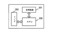
- FIG. 25 is a block diagram showing a configuration example of a computer that implements the temperature estimation system according to the first and second examples of the present invention.
- FIG. 26 is a diagram showing a thermal equivalent circuit model of a living body and a sensor.
- FIG. 27 is a diagram showing an example of the core body temperature estimated by the conventional method and the true core body temperature measured by the tympanic thermometer.
- FIG. 1 shows a schematic diagram in which the sensor 101a is arranged on the surface of the living body 100. As shown in FIG. In the living body 100 in the vicinity of the sensor 101a, the heat conduction equation shown in Equation (3) also holds.
- Values k, ⁇ , and c related to thermal characteristics are parameters that change from moment to moment. That is, although the values of k, ⁇ , and c change from moment to moment, they are assumed to be substantially uniform spatially. It can be said that the heat conduction equation of formula (3) in the vicinity of the sensor 101a is also related to the deep temperature T cbt . Also, the proportionality coefficient ⁇ related to the thermal resistance of the living body 100 corresponds to k/(c ⁇ ) and is therefore related to the heat conduction equation of Equation (3) in the vicinity of the sensor 101a.
- the core body temperature T cbt can be estimated from Equation (1) using the proportionality coefficient ⁇ estimated based on Equation (3).
- the core body temperature Tcbt can be estimated from the function f that indicates the relationship between the temperatures Tskin , Ttop , Tside , the heart rate N, and the core body temperature Tcbt .
- T cbt f (T skin , T top , T side , N) (4)
- the proportionality coefficient ⁇ can be estimated from the function g representing the relationship between the temperatures T skin , T top , T side and the heart rate N, and the proportionality coefficient ⁇ .
- ⁇ g(T skin , T top , T side , N) (5)
- equation (3) it is difficult to associate equation (3) with T skin , T top , T side , and N using elementary functions, but it is possible to associate them using dimensionless numbers or convolutional neural networks.
- FIG. 2 is a block diagram showing the configuration of the temperature estimation system according to the first embodiment of the present invention.
- the temperature estimation system includes a temperature measurement unit 1 (temperature measurement device), a heartbeat measurement unit 2 (heartbeat measurement device), a terminal 3 such as a PC (Personal Computer) or a smartphone, and a server device 4 .
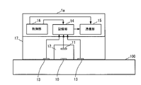
- the temperature measurement unit 1 includes a temperature sensor 10 that measures the temperature T skin of the skin surface of a living body 100 (subject such as a human body) and a temperature sensor 10 that measures the temperature T top inside the heat insulating material 12 directly above the temperature sensor 10 . 11, a heat insulating material 12 for holding the temperature sensor 10 and the temperature sensor 11, a temperature sensor 13 for measuring the temperature T side of the skin surface of the living body 100 at a position distant from the temperature sensor 10, and a storage for storing data.
- a storage unit 14, a communication unit 15 for transmitting data of temperatures T skin , T top , and T side to the terminal 3, and a control unit 16 for controlling reading/writing and communication of data to the storage unit 14 are provided.
- the temperature measurement unit 1 is arranged, for example, so that the surface of the housing 17 made of resin and the heat insulating material 12 exposed on this surface are in contact with the skin of the living body 100 .
- the temperature sensor 10 is provided on the surface of the heat insulating material 12 facing the living body.
- the temperature sensor 11 is provided inside the heat insulating material 12 right above the temperature sensor 10 .
- the heat insulating material 12 holds the temperature sensors 10 and 11 and serves as a resistor against heat flowing into the temperature sensors 11 .
- a material of the heat insulating material 12 is, for example, PET resin.
- the temperature sensor 13 is arranged at a position away from the temperature sensor 10 so as to be in contact with the skin of the living body 100 .
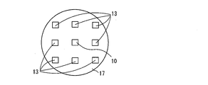
- FIG. 3 is a plan view showing the surface of the housing 17 of the temperature measurement unit 1 that is in contact with the living body 100.
- the temperature sensor 13 is arranged at one place around the temperature sensor 10 .
- a plurality of temperature sensors 13 may be arranged around the temperature sensor 10 .
- the heart rate measurement unit 2 measures the heart rate N of the living body 100 by, for example, a photoplethysmographic method.
- An example of the heartbeat measuring unit 2 is a wristwatch-type heartbeat measuring device.
- the server device 4 has a communication unit 40 for transmitting and receiving data to and from the terminal 3, a storage unit 41 for storing data, and converts the temperatures T skin , T side , T top and the heart rate N into tensors.
- a tensor generator 42 and a trained learner 43 for estimating the proportional coefficient ⁇ for the temperatures T skin , T side , T top or the proportional coefficient ⁇ for the temperatures T skin , T side , T top and the heart rate N.
- a machine learning unit 44 that performs machine learning of the learning device 43
- a temperature calculation unit 45 that calculates the core body temperature T cbt (internal temperature) of the living body 100 .
- FIG. 4 is a diagram showing another example of the temperature measurement unit.
- the temperature measurement unit 1a shown in FIG. FIG. 5 is a plan view showing the surface of the housing 17 of the temperature measuring unit 1a that contacts the living body 100. As shown in FIG. As shown in FIG. 5, a plurality of temperature sensors 13 are arranged around the temperature sensor 10 on the surface of the housing 17 of the temperature measurement unit 1a.
- FIG. 6 is a diagram showing another example of the temperature measurement unit.
- the temperature measurement unit 1b of FIG. 6 is provided with a housing 17 that houses the temperature sensors 10 and 13 and the heat insulating material 12, and a housing 18 that houses the storage unit 14, the communication unit 15, and the control unit 16. is.
- a wire 19 connects the temperature sensors 10 and 13 to the device on the housing 18 side.
- the arrangement of the temperature sensors 10 and 13 viewed from the living body 100 side is the same as in FIG.
- FIG. 7 is a diagram showing another example of the temperature measurement unit.
- a temperature measuring unit 1c of FIG. 7 is obtained by arranging a plurality of heat insulating materials 20 around the heat insulating material 12 in the temperature measuring unit 1b of FIG.
- the temperature sensor 10 is provided on the surface of the heat insulating material 12 facing the living body.
- the temperature sensor 13 is provided on the surface of the heat insulating material 20 facing the living body.
- Temperature sensor 11 is provided inside heat insulating materials 12 and 20 directly above temperature sensors 10 and 13 .
- the arrangement of the temperature sensors 10 and 13 viewed from the living body 100 side is the same as in FIG.
- FIG. 8 is a diagram showing another example of the temperature measurement unit.
- a temperature measuring unit 1d of FIG. 8 is obtained by arranging the temperature sensor 13 doubly around the temperature sensor 10 in the temperature measuring unit 1b of FIG.
- FIG. 9 is a plan view showing the surface of the housing 17 of the temperature measuring unit 1d that contacts the living body 100. As shown in FIG.
- FIG. 10 is a diagram showing another example of the temperature measurement unit.
- a temperature measurement unit 1e shown in FIG. 10 is the same as the temperature measurement unit 1a shown in FIG.
- Temperature sensors 10 , 11 , 13 are insulated from the outside air by internal structure 21 .
- the internal structure 21 is made of a material with good thermal conductivity, such as aluminum.
- the internal structure 21 has, for example, a truncated cone shape or a dome shape, and covers the temperature sensors 10 , 11 , 13 and the heat insulating material 12 .
- the arrangement of the temperature sensors 10 and 13 viewed from the living body 100 side is the same as in FIG.
- FIG. 11 is a diagram showing another example of the temperature measurement unit.
- a temperature measurement unit 1f in FIG. 11 has the same configuration as the temperature measurement unit 1e in FIG. However, the temperature sensor 13 is arranged outside the internal structure 21 instead of inside.
- FIG. 12 is a plan view showing the surface of the housing 17 of the temperature measuring unit 1f that contacts the living body 100. As shown in FIG.
- the temperature sensors 13 may be arranged as shown in FIG. Also, temperature sensors 13 may be arranged as shown in FIG.
- FIG. 15 is a diagram showing another example of the temperature measurement unit.
- a temperature measurement unit 1g of FIG. 15 incorporates a heart rate measurement unit 2 therein.
- the arrangement of the temperature sensors 10 and 13 viewed from the living body 100 side is the same as in FIG.
- FIG. 16 is a flowchart explaining the operation of the temperature estimation system of this embodiment. Note that FIG. 16 illustrates an example in which the heart rate measurement unit 2 is not used.
- the temperature sensors 10 of the temperature measuring units 1, 1a to 1g measure the temperature T skin of the skin surface of the living body 100.
- FIG. The temperature sensor 13 measures the temperature T side of the skin surface of the living body 100 at a position away from the temperature sensor 10 .
- the temperature sensor 11 measures the temperature T top inside the heat insulating material 12 at a position away from the living body 100 (step S100 in FIG. 16).
- the measurement data of the temperature sensors 10, 13, 11 are temporarily stored in the storage unit 14.
- FIG. Temperature sensors 10, 13, and 11 measure temperatures T skin , T side , and T top , respectively, at regular intervals, for example, every second.
- the communication units 15 of the temperature measurement units 1, 1a to 1g transmit data of the temperatures T skin , T side , and T top to the terminal 3 such as a PC or smart phone (step S101 in FIG. 16).
- the terminal 3 transmits the received temperature data T skin , T side , and T top to the server device 4 (step S102 in FIG. 16).
- the communication unit 40 of the server device 4 stores the received temperature data T skin , T side , and T top in the storage unit 41 .
- the tensor generation unit 42 of the server device 4 after the time ⁇ (for example, 1024 seconds) required to acquire the time-series data required for the data set used for deep learning (YES in step S103 in FIG. 16), Time-series data of temperatures T skin , T side , and T top for time ⁇ are converted into tensors (step S104 in FIG. 16).
- the tensor generation unit 42 subtracts 32° C. from each of the temperatures T skin , T side , and T top , and further subtracts Normalize the temperatures T skin , T side and T top respectively by dividing the latter data by 4°C. Then, as shown in the example of the tensor Te in FIG. 17, the time data of the normalized temperatures T skin , T side , and T top are arranged as pixels of the tensor (image).
- each temperature T top is normalized, and the data of each time of the normalized temperature T top are arranged as pixels of the tensor.
- each temperature T side is normalized, and the data of each time of the normalized temperature T side are arranged as pixels of the tensor. good.
- the learning device 43 of the server device 4 determines the relationship between the temperatures T skin , T side , and T top and the proportionality coefficient ⁇ , or the relationship between the temperatures T skin , T side , and T top , the heart rate N, and the proportionality coefficient ⁇ . It is a model constructed by software that models The learning device 43 outputs the estimation result of the proportionality coefficient ⁇ when the tensor is input from the tensor generator 42 (step S105 in FIG. 16). Examples of the learning device 43 include, for example, a CNN (Convolutional Neural Network) learning device.
- the learning device 43 needs to be trained in advance. Specifically, at the time of the preliminary test, time-series data of the temperatures T skin , T side , and T top of the living body 100 are acquired, and at the same time, time-series data of the true core body temperature T ref is acquired by, for example, an eardrum thermometer. .
- the time-series data of the temperatures T skin , T side , T top and the proportional coefficient ⁇ are converted into tensors by the tensor generator 42 .
- the machine learning unit 44 of the server device 4 performs machine learning of the learning device 43 using tensors. Specifically, the machine learning unit 44 uses the time-series data of the temperatures T skin , T side , and T top as input variables of the learning device 43 and the proportionality coefficient ⁇ as the output variable of the learning device 43 , the target output Machine learning is performed by the learner 43 so as to obtain variables. In this way, the learning device 43 can be trained before estimating the proportional coefficient ⁇ in step S105.
- the temperature calculation unit 45 of the server device 4 calculates the heat flux H skin of the skin surface of the living body 100 based on the temperatures T skin and T top using Equation (2), and calculates the temperature T skin and the heat flux H skin as Based on the proportional coefficient ⁇ estimated by the learning device 43, the core body temperature T cbt of the living body 100 is calculated by the equation (1) (step S106 in FIG. 16).
- the thermal resistance R skin of the heat insulating material 12 is pre-stored in the storage unit 41 .
- the temperature calculator 45 may calculate the core body temperature T cbt by Equation (7) without using the heat flux H skin .
- Tcbt Tskin + ⁇ ( Tskin ⁇ Ttop ) (7)
- the core body temperature T cbt is calculated using the latest values among the time-series data of the temperatures T skin and T top for the time ⁇ .
- representative values for example, average values
- the core body temperature T cbt may be calculated using the temperature T top measured by the temperature sensor 11 at one predetermined location.
- a representative value for example, an average value of the temperature T top measured by the temperature sensor 11 may be used.
- the core body temperature T cbt it is sufficient to know the core body temperature T cbt to the first decimal place in the range of about 30° C. to 42.0° C. with respect to the temperature accuracy of ⁇ 0.1° C. Therefore, when using a CNN learning device, for example, 120 output layers of the learning device 43 should be prepared.
- the estimated value of the core body temperature T cbt may be extremely large or small.
- the probability of occurrence of such an abnormal value of core body temperature T cbt is small. Therefore, abnormal values of the core body temperature T cbt can be sufficiently removed by statistical signal processing such as a particle filter and a first-order lag filter used in classical control.
- the communication unit 40 of the server device 4 transmits the data of the core body temperature T cbt calculated by the temperature calculation unit 45 to the terminal 3 (step S107 in FIG. 16).
- the terminal 3 displays the value of the core body temperature T cbt received from the server device 4 (step S108 in FIG. 16).
- the core body temperature T cbt is calculated for each time ⁇ .
- the estimation error of the core body temperature T cbt can be reduced.
- the heart rate measurement unit 2 measures the heart rate N (instantaneous heart rate) of the living body 100 at regular intervals, for example, every second (step S109 in FIG. 18).
- the heart rate measuring unit 2 transmits the data of the heart rate N to the terminal 3 (step S110 in FIG. 18).
- the data of the heart rate N is transmitted from the communication section 15 to the terminal 3 .
- the terminal 3 transmits the received temperature data T skin , T side , T top and heart rate data N to the server device 4 (step S102a in FIG. 18).
- the communication unit 40 of the server device 4 stores the received temperature data T skin , T side , and T top data and the heart rate N data in the storage unit 41 .
- the tensor generation unit 42 of the server device 4 After the lapse of time ⁇ (YES in step S103 in FIG. 18), the tensor generation unit 42 of the server device 4 generates time-series data of the temperatures T skin , T side , and T top for the time ⁇ and the heart rate N for the time ⁇ . is converted into a tensor (step S104a in FIG. 18).
- data of the heart rate N can be arranged as pixels of a tensor in the same manner as the temperatures T skin , T side , and T top .
- the learning device 43 of the server device 4 outputs the estimation result of the proportional coefficient ⁇ when the tensor is input from the tensor generator 42 (step S105a in FIG. 18).
- time-series data of the temperatures T skin , T side , and T top of the living body 100 and the heart rate N are acquired at the time of the preliminary test, and at the same time, the true core body temperature T ref is measured by the eardrum thermometer. Get the time series data of .
- Time-series data of the proportionality coefficient ⁇ is obtained by calculating the proportionality coefficient ⁇ according to the equation (6) using data of temperatures T skin , T top , and T ref at the same time.
- the tensor generator 42 converts the time-series data of the temperatures T skin , T side , and T top , the heart rate N, and the proportional coefficient ⁇ into tensors.
- the machine learning unit 44 of the server device 4 uses the time-series data of the temperatures T skin , T side , and T top and the time-series data of the heart rate N as input variables for the learning device 43 , and the proportional coefficient ⁇ as the output of the learning device 43 .
- Machine learning is performed by the learner 43 so as to obtain the target output variable as the variable. In this way, the learning device 43 can be trained before estimating the proportional coefficient ⁇ in step S105a.
- steps S106 to S108 are as described above. In this way, by using the data of the heart rate N, even when the exercise intensity of the living body 100 is high, the estimation error of the core body temperature T cbt can be reduced.
- FIG. 19A shows the core body temperature Tcbt estimated by the method of this embodiment when a person goes back and forth between indoors and outdoors in daily life, or lays down.
- Body temperature (tympanic temperature) T ref is shown in FIG. 19B.
- noise is suppressed and errors are corrected, and an estimation result close to the eardrum temperature is obtained. I understand.
- the core body temperature T cbt can be estimated with high accuracy without being affected by the blood flow of the living body, the outside temperature, or the wind. be able to.
- FIG. 20 is a block diagram showing the configuration of the server device of the temperature estimation system according to the second embodiment of the present invention.
- the server device 4a of this embodiment includes a communication unit 40, a storage unit 41, a tensor generation unit 42, and a plurality of learning devices 43 prepared in advance to correspond to the state of the living body 100 or the surrounding environment of the living body 100. -1 to 43-3, a machine learning unit 44, a temperature calculation unit 45, and a plurality of learners 43-1 to 43-3 based on at least one of temperatures T skin , T top , and heart rate N. and a selection unit 46 for selecting a learning device corresponding to the state of the living body 100 or the surrounding environment from among them.
- the configuration of the temperature measurement units 1, 1a to 1g is as explained in the first embodiment.
- the accuracy of the proportional coefficient ⁇ can be determined for the required temperature accuracy.
- the temperature accuracy is ⁇ 0.1° C.
- the coefficient of proportionality ⁇ which changes depending on the state of blood flow, is about 2.0 to 12.0, and it is sufficient to know to the first decimal place. . Therefore, when using a CNN learner, for example, if 100 output layers of the learner are prepared, the variation and accuracy of the proportional coefficient ⁇ can be dealt with. If the range of ⁇ can be limited to some extent, there is an advantage that the output layer can be made smaller than when estimating the core body temperature as it is.
- FIG. 21 is a flow chart for explaining the operation of the temperature estimation system of this embodiment.
- the temperature sensors 10, 13, 11 of the temperature measuring units 1, 1a-1g measure the temperatures T skin , T side , T top , for example, every second (step S200 in FIG. 21).
- the communication units 15 of the temperature measurement units 1, 1a to 1g transmit data of temperatures T skin , T side , and T top to the terminal 3 (step S201 in FIG. 21).
- the heart rate measurement unit 2 measures the heart rate N (instantaneous heart rate) of the living body 100 every second, for example (step S202 in FIG. 21).
- the heart rate measuring unit 2 transmits the data of the heart rate N to the terminal 3 (step S203 in FIG. 21).
- step S203 in FIG. 21 As shown in FIG. 15 , when the heart rate measurement unit 2 is provided inside the temperature measurement unit 1 g, data of the heart rate N is transmitted from the communication unit 15 to the terminal 3 .
- the terminal 3 transmits the received temperature data T skin , T side , T top and heart rate data N to the server device 4 a (step S 204 in FIG. 21).
- the tensor generation unit 42 of the server device 4a After the lapse of time ⁇ (YES in step S205 in FIG. 21), the tensor generation unit 42 of the server device 4a generates time-series data of the temperatures T skin , T side , and T top for the time ⁇ and the heart rate N for the time ⁇ . is converted into a tensor (step S206 in FIG. 21).
- the selection unit 46 of the server device 4a selects a learner to be used for estimating the proportionality coefficient ⁇ from the learners 43-1 to 43-3 prepared in advance.
- the proportional coefficient ⁇ is about 2 to 6, and about 40 output layers of the learning device are sufficient.
- it is desirable to widen the range of the output layer of the prepared learner because the deep body temperature changes greatly in a hot or cold environment.
- a learning device 43-1 corresponding to an exercise state or a hot/cold environment a learning device 43-2 corresponding to daily life, and a learning device 43-3 corresponding to a sleeping state are prepared in advance.
- the selection unit 46 selects a learning device to be used, using the skin surface temperature T skin , the temperature T top at the top of the sensor, or the heart rate N as an index.
- the selection unit 46 determines that the temperature T skin is lower than the threshold T skin — th . If either the heart rate N is higher than the threshold value N th (YES in step S207 in FIG. 21), it is determined that the learner 43-1 is to be used (step S208 in FIG. 21).
- Ttop_th_high is a temperature threshold for determining whether or not the environment is hot with high outside air.
- Ttop_th_low is a temperature threshold for determining whether or not the environment is cold with low outside air.
- T skin — th is a temperature value for determining whether the living body 100 is in a fever state due to a cold or the like, or whether it is in a fever state due to exercise.
- N th is a heart rate threshold for determining whether the living body 100 is in an exercise state.
- the selection unit 46 determines to use the learning device 43-3 (step S210).
- the threshold N th — low is a heart rate threshold for determining whether the living body 100 is in a sleeping state or in a resting state.
- the selection unit 46 determines that the learning device 43-2 is used (step S211 in FIG. 21).
- the latest values may be used to make the determinations in steps S207 and S209. Determination may be made using representative values (for example, average values) of the minute temperatures T skin , T top , and the heart rate N, respectively. Further, when the temperature T top is measured by a plurality of temperature sensors 11, the temperature T top measured by the temperature sensor 11 at one predetermined location may be used for the determination in step S207. A representative value (for example, an average value) of the temperature T top measured by the sensor 11 may be used for determination.
- the learner selected by the selector 46 outputs the estimation result of the proportional coefficient ⁇ for the tensor input from the tensor generator 42 (step 21 in FIG. 21). S212).
- the learning devices 43-1 to 43-3 need to be learned in advance according to their corresponding environments and usage scenes. That is, the learner 43-1 learns by acquiring the data of the temperatures T skin , T side , T top , and T ref and the heart rate N of the living body 100 under exercise or hot/cold environments.
- the learner 43-2 acquires data on the temperatures T skin , T side , T top , T ref and the heart rate N of the living body 100 during daily life and performs learning.
- the learner 43-3 acquires data of the temperatures T skin , T side , T top , and T ref and the heart rate N of the living body 100 in the sleeping state and performs learning.
- steps S213-S215 in FIG. 21 is the same as the processing of steps S106-S108 of the first embodiment.
- the core body temperature T cbt is calculated for each time ⁇ .
- the temperature sensors 10 and 13 may not come into direct contact with the skin of the living body 100.
- a thin sheet member made of a material having a small heat capacity such as PET resin is provided on the surface of the housing 17 on the living body side, and the temperature sensors 10 and 13 detect the skin surface temperatures T skin and T of the living body 100 via this member. You may make it measure side .
- the core body temperature T cbt is calculated after estimating the proportional coefficient ⁇ by the learners 43, 43-1 to 43-3.
- the core body temperature T cbt may be estimated by 43-3.
- the machine learning unit 44 of the server device 4, 4a uses the temperatures T skin , T side , T top , T Machine learning is performed by the learners 43, 43-1 to 43-3 using tensors converted from each time-series data of ref . Specifically, the machine learning unit 44 uses the time-series data of the temperatures T skin , T side , and T top as input variables for the learning devices 43 and 43-1 to 43-3, and the deep body temperature T ref as the learning device 43. , 43-1 to 43-3, machine learning is performed by the learners 43, 43-1 to 43-3 so as to obtain desired output variables.
- the machine learning unit 44 uses tensors converted from the respective time-series data of the temperatures T skin , T side , T top , and T ref acquired during the preliminary test and the heart rate N. Machine learning is performed by the learners 43, 43-1 to 43-3. Specifically, the machine learning unit 44 uses the time-series data of the temperatures T skin , T side , and T top and the time-series data of the heart rate N as input variables for the learning devices 43, 43-1 to 43-3, Using the deep body temperature T ref as an output variable of the learners 43, 43-1 to 43-3, machine learning is performed by the learners 43, 43-1 to 43-3 so as to obtain target output variables.
- the temperature calculator 45 becomes unnecessary when the core body temperature T cbt is estimated by the learners 43, 43-1 to 43-3.
- 22 and 23 show the operation for estimating core body temperature T cbt in the first embodiment
- FIG. 24 shows the operation for estimating core body temperature T cbt in the second embodiment.
- FIG. 22 shows an example in which the heart rate measuring section 2 is not used
- FIG. 23 shows an example in which the heart rate measuring section 2 is used.
- the learning device 43 outputs the result of estimating the core body temperature T cbt for the tensor input from the tensor generator 42 (step S106a).
- the learner selected by the selector 46 among the learners 43-1 to 43-3 outputs the result of estimating the core body temperature T cbt for the tensor input from the tensor generator 42 ( Step S213a).
- the storage unit 14, the communication unit 15, and the control unit 16 of the temperature measurement units 1, 1a to 1g described in the first and second embodiments are a computer having a CPU (Central Processing Unit), a storage device, and an interface. , can be implemented by a program that controls these hardware resources.
- a configuration example of this computer is shown in FIG.
- the computer comprises a CPU 200 , a storage device 201 and an interface device (I/F) 202 .
- the I/F 202 is connected to the temperature sensors 10, 11, 13, the hardware of the communication unit 15, and the like.
- a temperature estimation program for realizing the temperature estimation method of the present invention is stored in storage device 201 .
- the CPU 200 executes the processes described in the first and second embodiments according to programs stored in the storage device 201 .
- Each of the terminal 3 and the server devices 4 and 4a can also be implemented by a computer.
- the present invention can be applied to techniques for estimating the internal temperature of a subject such as a living body.
- Reference Signs List 1 1a to 1g temperature measurement unit 2 heartbeat measurement unit 3 terminal 4, 4a server device 10, 11, 13 temperature sensor 12, 20 heat insulator 14, 41 storage unit DESCRIPTION OF SYMBOLS 15, 40... Communication part 16... Control part 17, 18... Case, 19... Wiring, 21... Internal structure, 42... Tensor generation part, 43, 43-1 to 43-3... Learning device, 44... Machine learning unit, 45 temperature calculation unit, 46 selection unit.
Landscapes
- Health & Medical Sciences (AREA)
- Life Sciences & Earth Sciences (AREA)
- Physics & Mathematics (AREA)
- Medical Informatics (AREA)
- Surgery (AREA)
- Engineering & Computer Science (AREA)
- Biomedical Technology (AREA)
- Heart & Thoracic Surgery (AREA)
- Biophysics (AREA)
- Molecular Biology (AREA)
- Pathology (AREA)
- Animal Behavior & Ethology (AREA)
- General Health & Medical Sciences (AREA)
- Public Health (AREA)
- Veterinary Medicine (AREA)
- Cardiology (AREA)
- General Physics & Mathematics (AREA)
- Physiology (AREA)
- Measuring And Recording Apparatus For Diagnosis (AREA)
Abstract
温度推定システムは、生体(100)の表面の温度を計測する温度センサ(10)と、断熱材(12)の内部の温度を計測する温度センサ(11)と、温度センサ(10)から離れた位置の生体(100)の表面の温度を計測する温度センサ(13)と、温度センサ(10,11,13)の計測結果に基づいて生体(100)の熱抵抗に関連する比例係数を推定する学習器(43)と、温度センサ(10,11)の計測結果と比例係数に基づいて生体(100)の深部体温を算出する温度算出部(45)とを備える。
Description
本発明は、生体等の被検体の内部温度を非侵襲に精度良く推定する温度推定システムおよび温度推定方法に関するものである。
人間の持つ概日リズム、いわゆる体内時計は、睡眠、運動、仕事の質だけでなく、投薬の効果や疾患の発症など我々の体に関する様々なものと密接に関連していることが近年の時間生物学の研究からわかってきた。概日リズムは、ほぼ一定に刻まれているが、生活の中で暴露される光、運動、食生活、また、年齢や性別によっても大きく変化することが知られている。
概日リズムを測るための指標としては深部体温が知られている。しかし、一般に深部体温を測る方法は、直腸に温度計を挿入するか、あるいは耳を密閉した状態で鼓膜の温度を測るなどの方法であり、日々の活動中や睡眠中に深部体温を測る方法としては非常にストレスがかかる方法であった。
一方、生体の深部体温を非侵襲に測定する技術としては、疑似的に熱の流れを一次元等価回路モデルに置き換えて、生体の深部体温を推定する技術がある(特許文献1、非特許文献1参照)。
特許文献1、非特許文献1に開示された方法は、図26に示すように生体100とセンサ101の熱等価回路モデルを用いて、生体100の深部体温Tcbtを推定するものである。生体100の深部体温Tcbtは、生体100の表面に、熱抵抗Rsensorを有するセンサ101を置いたとき、生体100と接するセンサ101の表面側の温度Tskinと、生体100と接する面と反対側のセンサ101の上面の温度Ttopとから、式(1)を用いて推定できる。
Tcbt=Tskin+α×Hskin ・・・(1)
Tcbt=Tskin+α×Hskin ・・・(1)
ここで、Hskinは生体100の皮膚表面の熱流束であり、式(2)で表される。
Hskin=(Tskin-Ttop)/Rskin ・・・(2)
また、αは生体100の熱抵抗Rbodyに関連する比例係数、Rskinはセンサ101の熱抵抗である。
Hskin=(Tskin-Ttop)/Rskin ・・・(2)
また、αは生体100の熱抵抗Rbodyに関連する比例係数、Rskinはセンサ101の熱抵抗である。
しかしながら、特許文献1、非特許文献1に開示された従来の方法では、生体100からセンサ101を通って外気へ輸送される熱の流れを定常と仮定するため、生体100に風が当たったり、生体100が走ったり、生体100が温かい場所から急に冷たい場所に移動したりした場合には、深部体温Tcbtの推定に過渡的な誤差が生じるという課題があった。
また、従来の方法では、生体100の熱抵抗Rbodyを時間に関係なく一定とし、比例係数αも一定と仮定していた。しかし、生体100の皮膚近傍の血流状態は、生体100の姿勢や運動などでも変化する。このため、熱抵抗Rbodyは一定ではなく時々刻々と変化する。
人が日常生活の中で室内外を行き来したり、姿勢を横にしたりしたときに、従来の方法で推定した深部体温Tcbtと鼓膜温度計によって計測した真の深部体温(鼓膜温)Trefとを図27に示す。
真の深部体温Trefと、推定した深部体温Tcbtとの差は、人に風が当たったときに、センサ101の上面の温度Ttopと人の皮膚表面の温度Tskinとがそれぞれ定常状態に落ち着く迄の時間に差があることと、人の姿勢によって血流が変化することなどに起因している。また、風が絶えず変化しているような状態では、人が安静にしていて血流変化がないような状態でも、温度が定常状態に落ち着くことが期待できない。
また、従来の方法は、熱の流れが定常と仮定できる状態においても、測定の度に鼓膜温度計などの別のセンサを用いて比例係数αを逐一校正する必要がある。
また、従来の方法は、熱の流れが定常と仮定できる状態においても、測定の度に鼓膜温度計などの別のセンサを用いて比例係数αを逐一校正する必要がある。
物体内の温度分布は一般に下式の熱伝導方程式で記述することができる。

式(3)において、Tは温度、kは熱伝導率、cは熱容量、ρは密度、Qは内部での発熱である。Qは運動時等に発生する項である。Δは空間に関する二回微分の演算子で、3次元の直交座標系においては∂2/∂x2+∂2/∂y2+∂2/∂z2である。熱特性に関する値k,ρ,cは、人の肌の水分量、人の活動による毛細血管の拡張収縮、発汗、人の姿勢などで変化する血圧による血管の拡張収縮など、様々な要因で時々刻々と変化する。式(1)におけるαは、k/(ρc)に相当する比例係数であるため、比例係数αも時々刻々と変化することになる。
特許文献1、非特許文献1に開示された従来の方法では、1次元熱等価回路モデルを用いているが、先に述べているように熱容量cや密度ρといったパラメータが変化すると、1次元熱等価回路モデルは成り立たなくなる。言い換えれば、熱の流れが十分に安定している対象であれば内部温度を推定できるが、生体のような非定常な動的な対象では内部温度を推定することはできない。そのため、何らかの方法で式(3)を考慮に入れて内部温度(深部体温Tcbt)あるいは比例係数αを求める必要がある。
K.Kitamura et al.,"Development of a new method for the noninvasive measurement of deep body temperature without a heater",Medical Engineering & Physics,vol.32,No.1,pp.1-6,2010
本発明は、上記課題を解決するためになされたもので、測定の度に比例係数を校正することなく、生体等の被検体の内部温度の推定誤差を低減することができる温度推定システムおよび温度推定方法を提供することを目的とする。
本発明の温度推定システムは、断熱材と、被検体と向かい合う前記断熱材の面に設けられ、前記被検体の表面の温度を計測するように構成された第1の温度センサと、前記第1の温度センサの直上の前記断熱材の内部の温度を計測するように構成された第2の温度センサと、前記第1の温度センサから離れた位置の前記被検体の表面の温度を計測するように構成された第3の温度センサと、前記第1、第2、第3の温度センサの計測結果に基づいて前記被検体の熱抵抗に関連する比例係数を推定するように構成された学習器と、前記第1、第2の温度センサの計測結果と前記比例係数とに基づいて前記被検体の内部温度を算出するように構成された温度算出部とを備えることを特徴とするものである。
また、本発明の温度推定システムの1構成例は、前記被検体の心拍数を計測するように構成された心拍測定部をさらに備え、前記学習器は、前記第1、第2、第3の温度センサの計測結果と前記心拍測定部の計測結果とに基づいて前記比例係数を推定することを特徴とするものである。
また、本発明の温度推定システムの1構成例は、前記被検体の心拍数を計測するように構成された心拍測定部をさらに備え、前記学習器は、前記第1、第2、第3の温度センサの計測結果と前記心拍測定部の計測結果とに基づいて前記比例係数を推定することを特徴とするものである。
また、本発明の温度推定システムは、断熱材と、被検体と向かい合う前記断熱材の面に設けられ、前記被検体の表面の温度を計測するように構成された第1の温度センサと、前記第1の温度センサの直上の前記断熱材の内部の温度を計測するように構成された第2の温度センサと、前記第1の温度センサから離れた位置の前記被検体の表面の温度を計測するように構成された第3の温度センサと、前記第1、第2、第3の温度センサの計測結果に基づいて前記被検体の内部温度を推定するように構成された学習器とを備えることを特徴とするものである。
また、本発明の温度推定システムの1構成例は、前記被検体の心拍数を計測するように構成された心拍測定部をさらに備え、前記学習器は、前記第1、第2、第3の温度センサの計測結果と前記心拍測定部の計測結果とに基づいて前記被検体の内部温度を推定することを特徴とするものである。
また、本発明の温度推定システムの1構成例は、前記被検体の心拍数を計測するように構成された心拍測定部をさらに備え、前記学習器は、前記第1、第2、第3の温度センサの計測結果と前記心拍測定部の計測結果とに基づいて前記被検体の内部温度を推定することを特徴とするものである。
また、本発明の温度推定システムの1構成例は、前記被検体の状態または前記被検体の周囲の環境に対応するために予め用意された前記学習器を複数備え、前記第1の温度センサの計測結果と前記第2の温度センサの計測結果の少なくとも一方に基づいて、前記複数の学習器の中から、前記被検体の状態または前記被検体の周囲の環境に対応した学習器を前記推定のために選択するように構成された選択部をさらに備えることを特徴とするものである。
また、本発明の温度推定システムの1構成例は、前記被検体の状態または前記被検体の周囲の環境に対応するために予め用意された前記学習器を複数備え、前記第1の温度センサの計測結果と前記第2の温度センサの計測結果と前記心拍測定部の計測結果のうち少なくとも1つに基づいて、前記複数の学習器の中から、前記被検体の状態または前記被検体の周囲の環境に対応した学習器を前記推定のために選択するように構成された選択部をさらに備えることを特徴とするものである。
また、本発明の温度推定システムの1構成例は、前記被検体の状態または前記被検体の周囲の環境に対応するために予め用意された前記学習器を複数備え、前記第1の温度センサの計測結果と前記第2の温度センサの計測結果と前記心拍測定部の計測結果のうち少なくとも1つに基づいて、前記複数の学習器の中から、前記被検体の状態または前記被検体の周囲の環境に対応した学習器を前記推定のために選択するように構成された選択部をさらに備えることを特徴とするものである。
また、本発明の温度推定方法は、被検体と向かい合う断熱材の面に設けられた第1の温度センサによって前記被検体の表面の温度を計測する第1のステップと、前記第1の温度センサの直上の前記断熱材の内部の温度を第2の温度センサによって計測する第2のステップと、前記第1の温度センサから離れた位置の前記被検体の表面の温度を第3の温度センサによって計測する第3のステップと、前記第1、第2、第3のステップの計測結果に基づいて前記被検体の熱抵抗に関連する比例係数を学習済みの学習器によって推定する第4のステップと、前記第1、第2のステップの計測結果と前記比例係数とに基づいて前記被検体の内部温度を算出する第5のステップとを含むことを特徴とするものである。
また、本発明の温度推定方法の1構成例は、前記被検体の心拍数を計測する第6のステップをさらに含み、前記第4のステップは、前記第1、第2、第3のステップの計測結果と前記第6のステップの計測結果とに基づいて前記比例係数を推定するステップを含むことを特徴とするものである。
また、本発明の温度推定方法の1構成例は、前記被検体の心拍数を計測する第6のステップをさらに含み、前記第4のステップは、前記第1、第2、第3のステップの計測結果と前記第6のステップの計測結果とに基づいて前記比例係数を推定するステップを含むことを特徴とするものである。
本発明によれば、第1、第2、第3の温度センサの計測結果に基づいて、または第1、第2、第3の温度センサの計測結果と心拍測定部の計測結果とに基づいて比例係数を推定し、被検体の内部温度を算出することにより、測定の度に比例係数を校正することなく、被検体の内部温度を高精度に推定することができる。
また、本発明では、第1、第2、第3の温度センサの計測結果に基づいて、または第1、第2、第3の温度センサの計測結果と心拍測定部の計測結果とに基づいて被検体の内部温度を推定することにより、測定の度に比例係数を校正することなく、被検体の内部温度を高精度に推定することができる。
[発明の原理]
式(3)における∂T/∂t,ΔT,Qに相当する値を測定することができれば、式(3)のk/(cρ)を推定することができる。生体100の表面にセンサ101aを配置した模式図を図1に示す。センサ101aの近傍の生体100においても、式(3)に示す熱伝導方程式は成り立っている。
式(3)における∂T/∂t,ΔT,Qに相当する値を測定することができれば、式(3)のk/(cρ)を推定することができる。生体100の表面にセンサ101aを配置した模式図を図1に示す。センサ101aの近傍の生体100においても、式(3)に示す熱伝導方程式は成り立っている。
熱特性に関する値k,ρ,cは時々刻々と変化するパラメータであるが、k,ρ,cの空間的な特性の変化は比較的小さいという特徴がある。すなわち、k,ρ,cの値は時々刻々と変化するものの、空間的にはほぼ一様という仮定が成り立つ。センサ101aの近傍での式(3)の熱伝導方程式は、深部温度Tcbtとも関連していると言える。また、生体100の熱抵抗に関連する比例係数αは、k/(cρ)に対応するため、センサ101aの近傍での式(3)の熱伝導方程式と関連している。
したがって、センサ101aの近傍での式(3)の関係を基に深部体温Tcbtを推定することが可能である。また、式(3)を基に推定される比例係数αを用いて、式(1)から深部体温Tcbtを推定することができる。
ここで、センサ101aの近傍で式(3)の関係を考えると、∂T/∂t,ΔTを推定するには、温度の時系列データと生体100の表面の温度分布と生体100の表面からセンサ101aに流れ込む熱とを測る必要がある。例えば図1のように従来の温度Tskin,Ttopに加えて、Tskinから離れた位置の皮膚表面の温度Tsideを測定すれば、TskinとTsideとの差、およびTskinとTtopとの差からΔTに対応する値を求めることができる。一方、Qは、生体100の運動の強度と密接に関係しているため、生体100の心拍数Nや活動量Aから類推することができる。
つまり、温度Tskin,Ttop,Tsideおよび心拍数Nと、深部体温Tcbtとの関係を示す関数fにより、深部体温Tcbtを推定することができる。
Tcbt=f(Tskin,Ttop,Tside,N) ・・・(4)
Tcbt=f(Tskin,Ttop,Tside,N) ・・・(4)
また、温度Tskin,Ttop,Tsideおよび心拍数Nと、比例係数αとの関係を示す関数gにより、比例係数αを推定することができる。
α=g(Tskin,Ttop,Tside,N) ・・・(5)
α=g(Tskin,Ttop,Tside,N) ・・・(5)
一般に、式(3)とTskin,Ttop,Tside,Nとを初等関数で対応付けることは困難であるが、無次元数あるいは畳み込みニューラルネットワークを用いて対応付けることが可能である。
[第1の実施例]
以下、本発明の実施例について図面を参照して説明する。図2は本発明の第1の実施例に係る温度推定システムの構成を示すブロック図である。温度推定システムは、温度測定部1(温度測定装置)と、心拍測定部2(心拍測定装置)と、PC(Personal Computer)やスマートフォン等からなる端末3と、サーバ装置4とから構成される。
以下、本発明の実施例について図面を参照して説明する。図2は本発明の第1の実施例に係る温度推定システムの構成を示すブロック図である。温度推定システムは、温度測定部1(温度測定装置)と、心拍測定部2(心拍測定装置)と、PC(Personal Computer)やスマートフォン等からなる端末3と、サーバ装置4とから構成される。
温度測定部1は、生体100(人体などの被検体)の皮膚表面の温度Tskinを計測する温度センサ10と、温度センサ10の直上の断熱材12の内部の温度Ttopを計測する温度センサ11と、温度センサ10と温度センサ11とを保持する断熱材12と、温度センサ10から離れた位置の生体100の皮膚表面の温度Tsideを計測する温度センサ13と、データの記憶のための記憶部14と、温度Tskin,Ttop,Tsideのデータを端末3に送信する通信部15と、記憶部14へのデータの読み書きや通信を制御する制御部16とを備えている。
温度測定部1は、例えば樹脂製の筐体17の表面とこの表面に露出する断熱材12とが生体100の皮膚と接触するように配置される。温度センサ10は、断熱材12の生体側の面に設けられる。温度センサ11は、温度センサ10の直上の断熱材12の内部に設けられる。断熱材12は、温度センサ10と温度センサ11とを保持し、且つ温度センサ11に流入する熱に対する抵抗体となる。断熱材12の材料としては、例えばPET樹脂がある。また、温度センサ13は、温度センサ10から離れた位置に、生体100の皮膚と接触するように配置される。
図3は生体100と接する温度測定部1の筐体17の表面を示す平面図である。図3に示すように、温度センサ13は、温度センサ10の周囲の一箇所に配置される。後述のように、温度センサ13を、温度センサ10の周囲に複数個配置してもよい。
心拍測定部2は、例えば光電脈波法により生体100の心拍数Nを測定する。心拍測定部2の例としては、例えば腕時計型の心拍測定装置がある。
サーバ装置4は、端末3とのデータの送受信のための通信部40と、データの記憶のための記憶部41と、温度Tskin,Tside,Ttopと心拍数Nとをテンソルに変換するテンソル生成部42と、温度Tskin,Tside,Ttopに対する比例係数α、または温度Tskin,Tside,Ttopと心拍数Nとに対する比例係数αを推定するための学習済みの学習器43と、学習器43の機械学習を行う機械学習部44と、生体100の深部体温Tcbt(内部温度)を算出する温度算出部45とを備えている。
図4は温度測定部の別の例を示す図である。図4の温度測定部1aは、温度センサ13を複数備えるものである。図5は生体100と接する温度測定部1aの筐体17の表面を示す平面図である。図5に示すように、温度測定部1aの筐体17の表面には温度センサ10の周囲に複数の温度センサ13が配置されている。
図6は温度測定部の別の例を示す図である。図6の温度測定部1bは、温度センサ10,13と断熱材12とを収容する筐体17と、記憶部14と通信部15と制御部16とを収容する筐体18とを別にしたものである。温度センサ10,13と筐体18側のデバイスとの間は配線19によって接続されている。生体100側から見た温度センサ10,13の配置は図5と同様である。
図7は温度測定部の別の例を示す図である。図7の温度測定部1cは、図6の温度測定部1bにおいて、断熱材12の周囲に複数の断熱材20を配置したものである。温度センサ10は、断熱材12の生体側の面に設けられる。温度センサ13は、断熱材20の生体側の面に設けられる。温度センサ11は、温度センサ10,13の直上の断熱材12,20の内部に設けられる。生体100側から見た温度センサ10,13の配置は図5と同様である。
図8は温度測定部の別の例を示す図である。図8の温度測定部1dは、図6の温度測定部1bにおいて、温度センサ13を温度センサ10の周囲に2重に配置したものである。図9は生体100と接する温度測定部1dの筐体17の表面を示す平面図である。
図10は温度測定部の別の例を示す図である。図10の温度測定部1eは、図4の温度測定部1aにおいて、筐体17内に外気や風の影響を抑制する内部構造体21を設けたものである。温度センサ10,11,13は、内部構造体21によって外気から遮断される。内部構造体21は、例えばアルミのような熱伝導率が良い材料からなる。内部構造体21は、例えば円錐台状やドーム状の形状で、温度センサ10,11,13と断熱材12とを覆うようになっている。生体100側から見た温度センサ10,13の配置は図5と同様である。
図11は温度測定部の別の例を示す図である。図11の温度測定部1fは、図10の温度測定部1eと同様の構成を有する。ただし、温度センサ13を内部構造体21の内側ではなく、外側に配置している。図12は生体100と接する温度測定部1fの筐体17の表面を示す平面図である。
また、温度測定部1a,1b,1c,1e,1fにおいて、温度センサ13を図13のように配置してもよい。また、温度測定部1a,1b,1c,1e,1fにおいて、温度センサ13を図14のように配置してもよい。
図15は温度測定部の別の例を示す図である。図15の温度測定部1gは、心拍測定部2を内部に組み込んだものである。生体100側から見た温度センサ10,13の配置は図5と同様である。
図16は本実施例の温度推定システムの動作を説明するフローチャートである。なお、図16では、心拍測定部2を使用しない例について説明する。
温度測定部1,1a~1gの温度センサ10は、生体100の皮膚表面の温度Tskinを計測する。温度センサ13は、温度センサ10から離れた位置の生体100の皮膚表面の温度Tsideを計測する。温度センサ11は、生体100から遠ざかる位置の断熱材12の内部の温度Ttopを計測する(図16ステップS100)。温度センサ10,13,11の計測データは記憶部14にいったん格納される。温度センサ10,13,11は、それぞれ温度Tskin,Tside,Ttopを一定間隔、例えば1秒おきに計測する。
温度測定部1,1a~1gの通信部15は、温度Tskin,Tside,TtopのデータをPCやスマートフォン等からなる端末3に送信する(図16ステップS101)。
端末3は、受信した温度Tskin,Tside,Ttopのデータをサーバ装置4に送信する(図16ステップS102)。サーバ装置4の通信部40は、受信した温度Tskin,Tside,Ttopのデータを記憶部41に格納する。
端末3は、受信した温度Tskin,Tside,Ttopのデータをサーバ装置4に送信する(図16ステップS102)。サーバ装置4の通信部40は、受信した温度Tskin,Tside,Ttopのデータを記憶部41に格納する。
次に、サーバ装置4のテンソル生成部42は、深層学習に利用するデータセットに必要な時系列データの取得に必要な時間τ(例えば1024秒)の経過後に(図16ステップS103においてYES)、時間τ分の温度Tskin,Tside,Ttopの各時系列データをテンソルに変換する(図16ステップS104)。
例えば図17に示すような1秒おきに計測された温度Tskin,Tside,Ttopの時系列データがあったとする。テンソル生成部42は、温度Tskin,Tside,Ttopの1024秒分の各時系列データをテンソルに変換する場合、温度Tskin,Tside,Ttopからそれぞれ32℃を減算し、さらに減算後のデータを4℃で除算することにより、温度Tskin,Tside,Ttopをそれぞれ正規化する。そして、図17のテンソルTeの例で示すように、正規化した温度Tskin,Tside,Ttopのそれぞれの時間のデータをテンソル(画像)のピクセルとして並べていけばよい。
なお、複数の温度センサ11によって温度Ttopを計測する場合についても、それぞれの温度Ttopを正規化し、正規化した温度Ttopのそれぞれの時間のデータをテンソルのピクセルとして並べていけばよい。同様に、複数の温度センサ13によって温度Tsideを計測する場合についても、それぞれの温度度Tsideを正規化し、正規化した温度度Tsideのそれぞれの時間のデータをテンソルのピクセルとして並べていけばよい。
次に、サーバ装置4の学習器43は、温度Tskin,Tside,Ttopと比例係数αとの関係、または温度Tskin,Tside,Ttopと心拍数Nと比例係数αとの関係をモデル化した、ソフトウェア的に構築されたモデルである。学習器43は、テンソル生成部42からテンソルが入力されたときの比例係数αの推定結果を出力する(図16ステップS105)。学習器43の例としては、例えばCNN(Convolutional Neural Network)学習器がある。
学習器43は、事前に学習させておくことが必要である。具体的には、事前の試験時に、生体100の温度Tskin,Tside,Ttopの各時系列データを取得すると同時に、例えば鼓膜温度計によって真の深部体温Trefの時系列データを取得する。同時刻の温度Tskin,Ttop,Trefのデータを用いて、式(6)により比例係数αを算出することを時刻毎に行うことにより、比例係数αの時系列データを得る。
α=(Tref-Tskin)/(Tskin-Ttop) ・・・(6)
α=(Tref-Tskin)/(Tskin-Ttop) ・・・(6)
そして、温度Tskin,Tside,Ttopと比例係数αの各時系列データをテンソル生成部42によってテンソルに変換する。サーバ装置4の機械学習部44は、テンソルを用いて学習器43の機械学習を行う。具体的には、機械学習部44は、温度Tskin,Tside,Ttopの各時系列データを学習器43の入力変数とし、比例係数αを学習器43の出力変数として、目的とする出力変数が得られるように学習器43の機械学習を行う。こうして、ステップS105の比例係数αの推定の前に、学習器43を学習させておくことができる。
次に、サーバ装置4の温度算出部45は、温度Tskin,Ttopに基づいて生体100の皮膚表面の熱流束Hskinを式(2)により算出し、温度Tskinと熱流束Hskinと学習器43が推定した比例係数αとに基づいて生体100の深部体温Tcbtを式(1)により算出する(図16ステップS106)。断熱材12の熱抵抗Rskinは、記憶部41に予め記憶されている。なお、温度算出部45は、熱流束Hskinを用いずに、式(7)により深部体温Tcbtを算出してもよい。
Tcbt=Tskin+α×(Tskin-Ttop) ・・・(7)
Tcbt=Tskin+α×(Tskin-Ttop) ・・・(7)
深部体温Tcbtの算出に使用する温度Tskin,Ttopについては、時間τ分の温度Tskin,Ttopの時系列データのうち、それぞれ最新の値を用いて深部体温Tcbtを算出してもよいし、時間τ分の温度Tskin,Ttopのそれぞれの代表値(例えば平均値)を用いてもよい。また、複数の温度センサ11によって温度Ttopを計測する場合には、所定の一箇所の温度センサ11によって計測された温度Ttopを用いて深部体温Tcbtを算出してもよいし、複数の温度センサ11によって計測された温度Ttopの代表値(例えば平均値)を用いてもよい。
本実施例では、温度精度±0.1℃に対して30℃から42.0℃程度の範囲で小数点第1位程度まで深部体温Tcbtが分かれば充分である。そのため、例えばCNN学習器を用いる場合、学習器43の出力層を120個用意しておけばよい。
なお、学習器43の学習が十分でなかったり過学習なデータが含まれたりする場合は、深部体温Tcbtの推定値が極端に大きかったり小さかったりすることがある。このような深部体温Tcbtの異常値が生じる確率は小さい。このため、パーティクルフィルタ等の統計的な信号処理と古典制御で用いられる1次遅れ系のフィルタとによって、深部体温Tcbtの異常値を十分に取り除くことができる。
サーバ装置4の通信部40は、温度算出部45によって算出された深部体温Tcbtのデータを端末3に送信する(図16ステップS107)。
端末3は、サーバ装置4から受信した深部体温Tcbtの値を表示する(図16ステップS108)。
端末3は、サーバ装置4から受信した深部体温Tcbtの値を表示する(図16ステップS108)。
以上のようにして、時間τ毎に深部体温Tcbtが算出される。本実施例では、深部体温Tcbtの推定誤差を低減することができる。
なお、生体100の運動強度が大きいときは、生体100の心拍数Nも取得した方がよい。この場合の温度推定システムの動作を図18を用いて説明する。ステップS100,S101の処理は上記で説明したとおりである。
心拍測定部2は、一定間隔、例えば1秒おきに生体100の心拍数N(瞬時心拍数)を計測する(図18ステップS109)。心拍測定部2は、心拍数Nのデータを端末3に送信する(図18ステップS110)。なお、図15に示したように、温度測定部1gの内部に心拍測定部2が設けられている場合には、通信部15から端末3に心拍数Nのデータを送信する。
端末3は、受信した温度Tskin,Tside,Ttopのデータと心拍数Nのデータをサーバ装置4に送信する(図18ステップS102a)。サーバ装置4の通信部40は、受信した温度Tskin,Tside,Ttopのデータと心拍数Nのデータを記憶部41に格納する。
サーバ装置4のテンソル生成部42は、時間τの経過後に(図18ステップS103においてYES)、時間τ分の温度Tskin,Tside,Ttopと時間τ分の心拍数Nの各時系列データをテンソルに変換する(図18ステップS104a)。ここでは、温度Tskin,Tside,Ttopと同様に、心拍数Nのデータをテンソルのピクセルとして並べていけばよい。
サーバ装置4の学習器43は、テンソル生成部42からテンソルが入力されたときの比例係数αの推定結果を出力する(図18ステップS105a)。心拍数Nのデータを用いる場合、事前の試験時に、生体100の温度Tskin,Tside,Ttopと心拍数Nの各時系列データを取得すると同時に、鼓膜温度計によって真の深部体温Trefの時系列データを取得する。同時刻の温度Tskin,Ttop,Trefのデータを用いて、式(6)により比例係数αを算出することを時刻毎に行うことにより、比例係数αの時系列データを得る。
そして、温度Tskin,Tside,Ttopと心拍数Nと比例係数αの各時系列データをテンソル生成部42によってテンソルに変換する。サーバ装置4の機械学習部44は、温度Tskin,Tside,Ttopの各時系列データと心拍数Nの時系列データを学習器43の入力変数とし、比例係数αを学習器43の出力変数として、目的とする出力変数が得られるように学習器43の機械学習を行う。こうして、ステップS105aの比例係数αの推定の前に、学習器43を学習させておくことができる。
ステップS106~S108の処理は上記で説明したとおりである。こうして、心拍数Nのデータを用いることにより、生体100の運動強度が大きいときにおいても、深部体温Tcbtの推定誤差を低減することができる。
人が日常生活の中で室内外を行き来したり、姿勢を横にしたりしたときに、本実施例の方法で推定した深部体温Tcbtを図19Aに示し、鼓膜温度計によって計測した真の深部体温(鼓膜温)Trefを図19Bに示す。図27に示した従来の方法で推定した深部体温Tcbtと比べて、本実施例によれば、ノイズが抑制されると共に誤差が補正され、鼓膜温に近い推定結果が得られていることが分かる。本実施例によれば、測定の度に比例係数αを校正する必要がなく、かつ生体の血流の影響や、外気温や風の影響を受けずに高精度に深部体温Tcbtを推定することができる。
[第2の実施例]
次に、本発明の第2の実施例について説明する。図20は本発明の第2の実施例に係る温度推定システムのサーバ装置の構成を示すブロック図である。本実施例のサーバ装置4aは、通信部40と、記憶部41と、テンソル生成部42と、生体100の状態または生体100の周囲の環境に対応するために予め用意された複数の学習器43-1~43-3と、機械学習部44と、温度算出部45と、温度Tskin,Ttop、心拍数Nのうち少なくとも1つに基づいて、複数の学習器43-1~43-3の中から、生体100の状態または周囲の環境に対応した学習器を選択する選択部46とを備えている。
温度測定部1,1a~1gの構成は第1の実施例で説明したとおりである。
次に、本発明の第2の実施例について説明する。図20は本発明の第2の実施例に係る温度推定システムのサーバ装置の構成を示すブロック図である。本実施例のサーバ装置4aは、通信部40と、記憶部41と、テンソル生成部42と、生体100の状態または生体100の周囲の環境に対応するために予め用意された複数の学習器43-1~43-3と、機械学習部44と、温度算出部45と、温度Tskin,Ttop、心拍数Nのうち少なくとも1つに基づいて、複数の学習器43-1~43-3の中から、生体100の状態または周囲の環境に対応した学習器を選択する選択部46とを備えている。
温度測定部1,1a~1gの構成は第1の実施例で説明したとおりである。
必要となる温度精度に対して、比例係数αの精度を決めることができる。本実施例では、温度精度±0.1℃に対して、血流などの状態で変化する比例係数αは、およそ2.0から12.0程度で小数点第1位程度まで分かれば充分である。そのため、例えばCNN学習器を用いる場合、学習器の出力層を100個用意しておけば比例係数αの変化と精度に対応できる。αの範囲をある程度限定できる場合は深部体温をそのまま推定する場合よりも、出力層を小さくできるメリットがある。
図21は本実施例の温度推定システムの動作を説明するフローチャートである。第1の実施例と同様に、温度測定部1,1a~1gの温度センサ10,13,11は、温度Tskin,Tside,Ttopを例えば1秒おきに計測する(図21ステップS200)。
温度測定部1,1a~1gの通信部15は、温度Tskin,Tside,Ttopのデータを端末3に送信する(図21ステップS201)。
温度測定部1,1a~1gの通信部15は、温度Tskin,Tside,Ttopのデータを端末3に送信する(図21ステップS201)。
心拍測定部2は、例えば1秒おきに生体100の心拍数N(瞬時心拍数)を計測する(図21ステップS202)。心拍測定部2は、心拍数Nのデータを端末3に送信する(図21ステップS203)。図15に示したように、温度測定部1gの内部に心拍測定部2が設けられている場合には、通信部15から端末3に心拍数Nのデータを送信する。
端末3は、受信した温度Tskin,Tside,Ttopのデータと心拍数Nのデータをサーバ装置4aに送信する(図21ステップS204)。
サーバ装置4aのテンソル生成部42は、時間τの経過後に(図21ステップS205においてYES)、時間τ分の温度Tskin,Tside,Ttopと時間τ分の心拍数Nの各時系列データをテンソルに変換する(図21ステップS206)。
サーバ装置4aのテンソル生成部42は、時間τの経過後に(図21ステップS205においてYES)、時間τ分の温度Tskin,Tside,Ttopと時間τ分の心拍数Nの各時系列データをテンソルに変換する(図21ステップS206)。
次に、サーバ装置4aの選択部46は、予め用意された学習器43-1~43-3の中から、比例係数αの推定に使用する学習器を選択する。学習器の出力層の範囲を環境や利用シーンによって切り替えることで、より精度の高い推定を行うことができる。例えば、一般に健常者の睡眠中は、健常者が室内に居て外気温も安定している。このため、比例係数αは2から6程度であり、学習器の出力層は40個程度あればよい。一方、人が屋外で運動する場合は、暑熱または寒冷の環境下で深部体温の変化も大きいため、用意しておく学習器の出力層の範囲を広げておくことが望ましい。
そこで、深部体温の推定の高精度化のため、学習器を複数個用意しておき、場面ごとに切り替えることが望ましい。例えば運動状態または暑熱・寒冷の環境に対応する学習器43-1と、日常生活に対応する学習器43-2と、睡眠状態に対応する学習器43-3とを予め用意する。選択部46は、皮膚表面の温度Tskin、センサ上部の温度Ttop、または心拍数Nを指標として、使用する学習器を選択する。
具体的には、選択部46は、温度Ttopが閾値Ttop_th_highより高い場合、温度Ttopが閾値Ttop_th_lowより低い場合、温度Tskinが閾値Tskin_thより高い場合、心拍数Nが閾値Nthより高い場合のいずれかが成立するときに(図21ステップS207においてYES)、学習器43-1を使用すると判定する(図21ステップS208)。
Ttop_th_highは、外気が高い暑熱環境下か否かを判定するための温度閾値である。Ttop_th_lowは、外気が低い寒冷環境下か否かを判定するための温度閾値である。Tskin_thは、生体100が風邪等による発熱状態か否か、または運動による発熱状態か否かを判定するための温度値である。Nthは、生体100が運動状態か否かを判定するための心拍数閾値である。
一方、選択部46は、ステップS207の判定が成立せず、心拍数Nが閾値Nth_lowより低いときには(図21ステップS209においてYES)、学習器43-3を使用すると判定する(図21ステップS210)。閾値Nth_lowは、生体100が睡眠状態か否か、または安静な状態か否かを判定するための心拍数閾値である。
選択部46は、ステップS207,S209の判定がいずれも成立しないときには(ステップS209においてNO)、学習器43-2を使用すると判定する(図21ステップS211)。
なお、時間τ分の温度Tskin,Ttopと時間τ分の心拍数Nの各時系列データのうち、それぞれ最新の値を用いてステップS207,S209の判定を行ってもよいし、時間τ分の温度Tskin,Ttop、心拍数Nのそれぞれの代表値(例えば平均値)を用いて判定を行ってもよい。また、複数の温度センサ11によって温度Ttopを計測する場合には、所定の一箇所の温度センサ11によって計測された温度Ttopを用いてステップS207の判定を行ってもよいし、複数の温度センサ11によって計測された温度Ttopの代表値(例えば平均値)を用いて判定を行ってもよい。
サーバ装置4aの学習器43-1~43-3のうち、選択部46によって選択された学習器は、テンソル生成部42から入力されたテンソルに対する比例係数αの推定結果を出力する(図21ステップS212)。
学習器43-1~43-3は、それぞれ対応する環境や利用シーンに応じて事前に学習しておく必要がある。すなわち、学習器43-1については、運動状態または暑熱・寒冷の環境下での生体100の温度Tskin,Tside,Ttop,Trefと心拍数Nのデータを取得して学習を行う。学習器43-2については、日常の生活中の生体100の温度Tskin,Tside,Ttop,Trefと心拍数Nのデータを取得して学習を行う。学習器43-3については、睡眠状態の生体100の温度Tskin,Tside,Ttop,Trefと心拍数Nのデータを取得して学習を行う。
図21のステップS213~S215の処理は、第1の実施例のステップS106~S108の処理と同じである。
以上のようにして、時間τ毎に深部体温Tcbtが算出される。学習器43-1~43-3をクラウドサーバ側に設ける場合、学習器43-1~43-3の学習を逐次進め、利用しながら更新と高精度化を進めていくことができる。
以上のようにして、時間τ毎に深部体温Tcbtが算出される。学習器43-1~43-3をクラウドサーバ側に設ける場合、学習器43-1~43-3の学習を逐次進め、利用しながら更新と高精度化を進めていくことができる。
なお、温度センサ10,13の保護のため、温度センサ10,13が生体100の皮膚と直に触れないようにしてもよい。例えばPET樹脂などの熱容量の小さい材料からなる薄いシート状の部材を生体側の筐体17の表面に設け、この部材を介して温度センサ10,13が生体100の皮膚表面の温度Tskin,Tsideを計測するようにしてもよい。
また、第1、第2の実施例では、学習器43,43-1~43-3によって比例係数αを推定した後に深部体温Tcbtを算出しているが、学習器43,43-1~43-3によって深部体温Tcbtを推定するようにしてもよい。
また、第1、第2の実施例では、学習器43,43-1~43-3によって比例係数αを推定した後に深部体温Tcbtを算出しているが、学習器43,43-1~43-3によって深部体温Tcbtを推定するようにしてもよい。
学習器43,43-1~43-3によって深部体温Tcbtを推定する場合、サーバ装置4,4aの機械学習部44は、事前の試験時に取得した温度Tskin,Tside,Ttop,Trefの各時系列データから変換されたテンソルを用いて学習器43,43-1~43-3の機械学習を行う。具体的には、機械学習部44は、温度Tskin,Tside,Ttopの各時系列データを学習器43,43-1~43-3の入力変数とし、深部体温Trefを学習器43,43-1~43-3の出力変数として、目的とする出力変数が得られるように学習器43,43-1~43-3の機械学習を行う。
心拍数Nのデータを用いる場合、機械学習部44は、事前の試験時に取得した温度Tskin,Tside,Ttop,Trefと心拍数Nの各時系列データから変換されたテンソルを用いて学習器43,43-1~43-3の機械学習を行う。具体的には、機械学習部44は、温度Tskin,Tside,Ttopの各時系列データと心拍数Nの時系列データを学習器43,43-1~43-3の入力変数とし、深部体温Trefを学習器43,43-1~43-3の出力変数として、目的とする出力変数が得られるように学習器43,43-1~43-3の機械学習を行う。
学習器43,43-1~43-3によって深部体温Tcbtを推定する場合、温度算出部45が不要になることは言うまでもない。第1の実施例において深部体温Tcbtを推定する場合の動作を図22、図23に示し、第2の実施例において深部体温Tcbtを推定する場合の動作を図24に示す。図22は心拍測定部2を使用しない例を示し、図23は心拍測定部2を使用する例を示している。
図22、図23の例では、学習器43は、テンソル生成部42から入力されたテンソルに対する深部体温Tcbtの推定結果を出力する(ステップS106a)。
図24の例では、学習器43-1~43-3のうち、選択部46によって選択された学習器は、テンソル生成部42から入力されたテンソルに対する深部体温Tcbtの推定結果を出力する(ステップS213a)。
図24の例では、学習器43-1~43-3のうち、選択部46によって選択された学習器は、テンソル生成部42から入力されたテンソルに対する深部体温Tcbtの推定結果を出力する(ステップS213a)。
なお、比例係数αに対して深部体温Tcbtは変動が連続的かつ緩やかなので、通常は比例係数αを推定した方が精度がよい。
第1、第2の実施例で説明した温度測定部1,1a~1gの記憶部14と通信部15と制御部16とは、CPU(Central Processing Unit)、記憶装置及びインタフェースを備えたコンピュータと、これらのハードウェア資源を制御するプログラムによって実現することができる。このコンピュータの構成例を図25に示す。
コンピュータは、CPU200と、記憶装置201と、インタフェース装置(I/F)202とを備えている。I/F202には、温度センサ10,11,13、通信部15のハードウェア等が接続される。このようなコンピュータにおいて、本発明の温度推定方法を実現させるための温度推定プログラムは、記憶装置201に格納される。CPU200は、記憶装置201に格納されたプログラムに従って第1、第2の実施例で説明した処理を実行する。
端末3とサーバ装置4,4aの各々についてもコンピュータによって実現することができる。
端末3とサーバ装置4,4aの各々についてもコンピュータによって実現することができる。
本発明は、生体等の被検体の内部温度を推定する技術に適用することができる。
1,1a~1g…温度測定部、2…心拍測定部、3…端末、4,4a…サーバ装置、10,11,13…温度センサ、12,20…断熱材、14,41…記憶部、15,40…通信部、16…制御部、17,18…筐体、19…配線、21…内部構造体、42…テンソル生成部、43,43-1~43-3…学習器、44…機械学習部、45…温度算出部、46…選択部。
Claims (8)
- 断熱材と、
被検体と向かい合う前記断熱材の面に設けられ、前記被検体の表面の温度を計測するように構成された第1の温度センサと、
前記第1の温度センサの直上の前記断熱材の内部の温度を計測するように構成された第2の温度センサと、
前記第1の温度センサから離れた位置の前記被検体の表面の温度を計測するように構成された第3の温度センサと、
前記第1、第2、第3の温度センサの計測結果に基づいて前記被検体の熱抵抗に関連する比例係数を推定するように構成された学習器と、
前記第1、第2の温度センサの計測結果と前記比例係数とに基づいて前記被検体の内部温度を算出するように構成された温度算出部とを備えることを特徴とする温度推定システム。 - 請求項1記載の温度推定システムにおいて、
前記被検体の心拍数を計測するように構成された心拍測定部をさらに備え、
前記学習器は、前記第1、第2、第3の温度センサの計測結果と前記心拍測定部の計測結果とに基づいて前記比例係数を推定することを特徴とする温度推定システム。 - 断熱材と、
被検体と向かい合う前記断熱材の面に設けられ、前記被検体の表面の温度を計測するように構成された第1の温度センサと、
前記第1の温度センサの直上の前記断熱材の内部の温度を計測するように構成された第2の温度センサと、
前記第1の温度センサから離れた位置の前記被検体の表面の温度を計測するように構成された第3の温度センサと、
前記第1、第2、第3の温度センサの計測結果に基づいて前記被検体の内部温度を推定するように構成された学習器とを備えることを特徴とする温度推定システム。 - 請求項3記載の温度推定システムにおいて、
前記被検体の心拍数を計測するように構成された心拍測定部をさらに備え、
前記学習器は、前記第1、第2、第3の温度センサの計測結果と前記心拍測定部の計測結果とに基づいて前記被検体の内部温度を推定することを特徴とする温度推定システム。 - 請求項1または3記載の温度推定システムにおいて、
前記被検体の状態または前記被検体の周囲の環境に対応するために予め用意された前記学習器を複数備え、
前記第1の温度センサの計測結果と前記第2の温度センサの計測結果の少なくとも一方に基づいて、前記複数の学習器の中から、前記被検体の状態または前記被検体の周囲の環境に対応した学習器を前記推定のために選択するように構成された選択部をさらに備えることを特徴とする温度推定システム。 - 請求項2または4記載の温度推定システムにおいて、
前記被検体の状態または前記被検体の周囲の環境に対応するために予め用意された前記学習器を複数備え、
前記第1の温度センサの計測結果と前記第2の温度センサの計測結果と前記心拍測定部の計測結果のうち少なくとも1つに基づいて、前記複数の学習器の中から、前記被検体の状態または前記被検体の周囲の環境に対応した学習器を前記推定のために選択するように構成された選択部をさらに備えることを特徴とする温度推定システム。 - 被検体と向かい合う断熱材の面に設けられた第1の温度センサによって前記被検体の表面の温度を計測する第1のステップと、
前記第1の温度センサの直上の前記断熱材の内部の温度を第2の温度センサによって計測する第2のステップと、
前記第1の温度センサから離れた位置の前記被検体の表面の温度を第3の温度センサによって計測する第3のステップと、
前記第1、第2、第3のステップの計測結果に基づいて前記被検体の熱抵抗に関連する比例係数を学習済みの学習器によって推定する第4のステップと、
前記第1、第2のステップの計測結果と前記比例係数とに基づいて前記被検体の内部温度を算出する第5のステップとを含むことを特徴とする温度推定方法。 - 請求項7記載の温度推定方法において、
前記被検体の心拍数を計測する第6のステップをさらに含み、
前記第4のステップは、前記第1、第2、第3のステップの計測結果と前記第6のステップの計測結果とに基づいて前記比例係数を推定するステップを含むことを特徴とする温度推定方法。
Priority Applications (3)
| Application Number | Priority Date | Filing Date | Title |
|---|---|---|---|
| US18/563,148 US20240260837A1 (en) | 2021-06-15 | 2021-06-15 | Temperature estimation system and temperature estimation method |
| JP2023528810A JP7593494B2 (ja) | 2021-06-15 | 2021-06-15 | 温度推定システムおよび温度推定方法 |
| PCT/JP2021/022707 WO2022264271A1 (ja) | 2021-06-15 | 2021-06-15 | 温度推定システムおよび温度推定方法 |
Applications Claiming Priority (1)
| Application Number | Priority Date | Filing Date | Title |
|---|---|---|---|
| PCT/JP2021/022707 WO2022264271A1 (ja) | 2021-06-15 | 2021-06-15 | 温度推定システムおよび温度推定方法 |
Publications (1)
| Publication Number | Publication Date |
|---|---|
| WO2022264271A1 true WO2022264271A1 (ja) | 2022-12-22 |
Family
ID=84526315
Family Applications (1)
| Application Number | Title | Priority Date | Filing Date |
|---|---|---|---|
| PCT/JP2021/022707 Ceased WO2022264271A1 (ja) | 2021-06-15 | 2021-06-15 | 温度推定システムおよび温度推定方法 |
Country Status (3)
| Country | Link |
|---|---|
| US (1) | US20240260837A1 (ja) |
| JP (1) | JP7593494B2 (ja) |
| WO (1) | WO2022264271A1 (ja) |
Citations (6)
| Publication number | Priority date | Publication date | Assignee | Title |
|---|---|---|---|---|
| US20180092545A1 (en) * | 2016-09-30 | 2018-04-05 | Samsung Electronics Co., Ltd. | Wrist temperature rhythm acquisition apparatus and method, core temperature rhythm acquisition apparatus and method, and wearable device |
| JP2018183564A (ja) * | 2017-04-26 | 2018-11-22 | パナソニックIpマネジメント株式会社 | 深部体温測定装置、深部体温測定システム及び深部体温測定方法 |
| US20190323895A1 (en) * | 2018-04-24 | 2019-10-24 | Helen Of Troy Limited | System and method for human temperature regression using multiple structures |
| JP2019207124A (ja) * | 2018-05-28 | 2019-12-05 | 日本電信電話株式会社 | 生体内温度測定装置および生体内温度測定方法 |
| JP2020003291A (ja) * | 2018-06-27 | 2020-01-09 | 日本電信電話株式会社 | 生体内温度測定装置および生体内温度測定方法 |
| JP2021010721A (ja) * | 2019-07-08 | 2021-02-04 | ダイキン工業株式会社 | 学習装置、推定装置、及び、環境調整システム。 |
-
2021
- 2021-06-15 JP JP2023528810A patent/JP7593494B2/ja active Active
- 2021-06-15 US US18/563,148 patent/US20240260837A1/en active Pending
- 2021-06-15 WO PCT/JP2021/022707 patent/WO2022264271A1/ja not_active Ceased
Patent Citations (6)
| Publication number | Priority date | Publication date | Assignee | Title |
|---|---|---|---|---|
| US20180092545A1 (en) * | 2016-09-30 | 2018-04-05 | Samsung Electronics Co., Ltd. | Wrist temperature rhythm acquisition apparatus and method, core temperature rhythm acquisition apparatus and method, and wearable device |
| JP2018183564A (ja) * | 2017-04-26 | 2018-11-22 | パナソニックIpマネジメント株式会社 | 深部体温測定装置、深部体温測定システム及び深部体温測定方法 |
| US20190323895A1 (en) * | 2018-04-24 | 2019-10-24 | Helen Of Troy Limited | System and method for human temperature regression using multiple structures |
| JP2019207124A (ja) * | 2018-05-28 | 2019-12-05 | 日本電信電話株式会社 | 生体内温度測定装置および生体内温度測定方法 |
| JP2020003291A (ja) * | 2018-06-27 | 2020-01-09 | 日本電信電話株式会社 | 生体内温度測定装置および生体内温度測定方法 |
| JP2021010721A (ja) * | 2019-07-08 | 2021-02-04 | ダイキン工業株式会社 | 学習装置、推定装置、及び、環境調整システム。 |
Non-Patent Citations (1)
| Title |
|---|
| MATSUNAGA, DAICHI ET AL.: "Examination on the estimation of human core body temperature using non-invasive measurements method for changes in convection of outside air", PROCEEDINGS OF THE 2019 IEICE COMMUNICATIONS SOCIETY CONFERENCE, 27 August 2019 (2019-08-27), pages 379, ISSN: 1349-1415 * |
Also Published As
| Publication number | Publication date |
|---|---|
| JP7593494B2 (ja) | 2024-12-03 |
| JPWO2022264271A1 (ja) | 2022-12-22 |
| US20240260837A1 (en) | 2024-08-08 |
Similar Documents
| Publication | Publication Date | Title |
|---|---|---|
| JP6763142B2 (ja) | 内部温度測定装置、リスト装着型装置及び内部温度測定方法 | |
| US9410854B2 (en) | Methods and devices for measuring core body temperature | |
| EP2459976B1 (en) | Sensor and method for determining a core body temperature | |
| RU2602676C2 (ru) | Устройство для обнаружения лихорадки | |
| JP7073919B2 (ja) | 生体内温度測定装置および生体内温度測定方法 | |
| JP6973296B2 (ja) | 生体内温度測定装置および生体内温度測定方法 | |
| JP2016508755A (ja) | カロリーエネルギー摂取量及び/又は主要栄養素組成を推定するためのシステム及び装置 | |
| CN111741710B (zh) | 核心温度检测系统和方法 | |
| CN109154527A (zh) | 校准用于测量个体体温的热通量传感器 | |
| JP7741797B2 (ja) | 温度測定装置および温度測定方法 | |
| CN117204825A (zh) | 鼓膜温度测量装置、血糖测量方法、系统及设备 | |
| JP7593494B2 (ja) | 温度推定システムおよび温度推定方法 | |
| US20250277706A1 (en) | System and method for temperature determination | |
| CN114061780A (zh) | 一种用于可穿戴设备的人体体温监测系统及方法 | |
| CN117204847A (zh) | 血糖测量方法、设备及介质 | |
| WO2019184677A1 (zh) | 连续测量核心体温方法及装置 | |
| EP4374779B1 (en) | Electronic device and method of estimating blood flow information using the same | |
| Finvers et al. | Wireless temporal artery bandage thermometer | |
| JP7786610B2 (ja) | 温度測定装置、方法およびプログラム | |
| JP7392837B2 (ja) | 温度測定装置および温度測定方法 | |
| JP2022541008A (ja) | 快適性及び精度を最適化するための方法を備えた装着可能な生体電位パッチ | |
| CN115655472B (zh) | 体温测量方法、装置、电子设备及可读存储介质 | |
| JP7683807B2 (ja) | 温度測定装置 | |
| JP7761135B2 (ja) | 発汗分析装置および方法 | |
| CN209391915U (zh) | 连续测量核心体温装置 |
Legal Events
| Date | Code | Title | Description |
|---|---|---|---|
| 121 | Ep: the epo has been informed by wipo that ep was designated in this application |
Ref document number: 21945950 Country of ref document: EP Kind code of ref document: A1 |
|
| WWE | Wipo information: entry into national phase |
Ref document number: 2023528810 Country of ref document: JP |
|
| NENP | Non-entry into the national phase |
Ref country code: DE |
|
| 122 | Ep: pct application non-entry in european phase |
Ref document number: 21945950 Country of ref document: EP Kind code of ref document: A1 |