WO2022260010A1 - 車両制御装置、車両制御プログラム、及び車両制御システム - Google Patents
車両制御装置、車両制御プログラム、及び車両制御システム Download PDFInfo
- Publication number
- WO2022260010A1 WO2022260010A1 PCT/JP2022/022822 JP2022022822W WO2022260010A1 WO 2022260010 A1 WO2022260010 A1 WO 2022260010A1 JP 2022022822 W JP2022022822 W JP 2022022822W WO 2022260010 A1 WO2022260010 A1 WO 2022260010A1
- Authority
- WO
- WIPO (PCT)
- Prior art keywords
- command
- vehicle control
- output
- commands
- unit
- Prior art date
- Legal status (The legal status is an assumption and is not a legal conclusion. Google has not performed a legal analysis and makes no representation as to the accuracy of the status listed.)
- Ceased
Links
Images




Classifications
-
- B—PERFORMING OPERATIONS; TRANSPORTING
- B60—VEHICLES IN GENERAL
- B60R—VEHICLES, VEHICLE FITTINGS, OR VEHICLE PARTS, NOT OTHERWISE PROVIDED FOR
- B60R16/00—Electric or fluid circuits specially adapted for vehicles and not otherwise provided for; Arrangement of elements of electric or fluid circuits specially adapted for vehicles and not otherwise provided for
- B60R16/02—Electric or fluid circuits specially adapted for vehicles and not otherwise provided for; Arrangement of elements of electric or fluid circuits specially adapted for vehicles and not otherwise provided for electric constitutive elements
- B60R16/037—Electric or fluid circuits specially adapted for vehicles and not otherwise provided for; Arrangement of elements of electric or fluid circuits specially adapted for vehicles and not otherwise provided for electric constitutive elements for occupant comfort, e.g. for automatic adjustment of appliances according to personal settings, e.g. seats, mirrors, steering wheel
-
- B—PERFORMING OPERATIONS; TRANSPORTING
- B60—VEHICLES IN GENERAL
- B60R—VEHICLES, VEHICLE FITTINGS, OR VEHICLE PARTS, NOT OTHERWISE PROVIDED FOR
- B60R16/00—Electric or fluid circuits specially adapted for vehicles and not otherwise provided for; Arrangement of elements of electric or fluid circuits specially adapted for vehicles and not otherwise provided for
- B60R16/02—Electric or fluid circuits specially adapted for vehicles and not otherwise provided for; Arrangement of elements of electric or fluid circuits specially adapted for vehicles and not otherwise provided for electric constitutive elements
-
- G—PHYSICS
- G06—COMPUTING OR CALCULATING; COUNTING
- G06F—ELECTRIC DIGITAL DATA PROCESSING
- G06F8/00—Arrangements for software engineering
- G06F8/30—Creation or generation of source code
-
- G—PHYSICS
- G06—COMPUTING OR CALCULATING; COUNTING
- G06F—ELECTRIC DIGITAL DATA PROCESSING
- G06F9/00—Arrangements for program control, e.g. control units
- G06F9/06—Arrangements for program control, e.g. control units using stored programs, i.e. using an internal store of processing equipment to receive or retain programs
- G06F9/44—Arrangements for executing specific programs
- G06F9/4401—Bootstrapping
- G06F9/4411—Configuring for operating with peripheral devices; Loading of device drivers
Definitions
- the present disclosure relates to a vehicle control device, a vehicle control program, and a vehicle control system configured to control a controlled object.
- Patent Document 1 discloses a configuration in which a vehicle includes a program called an adapter for adapting a command from an application to a control program.
- the adapter has a function for adding or changing an application that provides services, and the control program has a function for controlling a controlled object such as a voice control device.
- Patent Document 1 has a wide range of programs to be modified, such as the need to modify not only the adapter but also the control program when making changes such as adding or updating applications. problem was found. This is because if a plurality of conflicting commands are input to the control program when the application is changed, the operation of the control program may malfunction.
- One aspect of the present disclosure is that, in a vehicle control device, a vehicle control program, and a vehicle control system configured to control a controlled object, it is possible to narrow the range of the program to be modified when the application is changed. It is to provide the technology that is possible.
- One aspect of the present disclosure is a vehicle control device located in a vehicle and configured to control a controlled object by transmitting commands to a control program for controlling the controlled object.
- the control program has multiple interfaces for exchanging parameters.
- the vehicle control device includes at least one first command section, multiple output sections, and at least one second command section.
- the first command unit is configured to output a first command, which is a command that does not specify an interface, to the control program.
- the output unit is configured to output the input command to the corresponding interface.
- the second command section selects an output section to transmit a command from among the plurality of output sections based on the first command, and transmits a command corresponding to the first command to the selected output section. is configured to cause each of the selected outputs to send to the interface a second command representing the output.
- Each of the plurality of output units is configured such that, for each of the plurality of interfaces, only one output unit transmits the second command to the interface.
- each of the multiple output units is configured so that only one output unit transmits the second command to each of the multiple interfaces. Therefore, when changing the first command section such as an application, it is possible to eliminate the need to change the control program only by changing the configuration of the second command section. Therefore, the range of programs to be corrected can be narrowed.
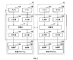
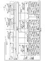
- FIG. 2 is a block diagram showing the hardware configuration of the vehicle control system;
- FIG. 2 is a block diagram showing the software configuration of an ECU;
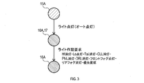
- FIG. It is an explanatory view showing a processing procedure in the first operation example.
- FIG. 11 is an explanatory diagram showing a processing procedure in a second operation example;
- FIG. 11 is an explanatory diagram showing a processing procedure in a third operation example;
- FIG. 11 is an explanatory diagram showing a processing procedure in a fourth operation example;
- FIG. 14 is an explanatory diagram showing a processing procedure in a fifth operation example;
- FIG. 11 is an explanatory diagram showing destinations of commands by an output unit in another embodiment; It is a block diagram showing an example of the hardware constitutions of the vehicle control system in other embodiments. 4 is a flow chart showing basic processing executed in a vehicle control system; FIG. 11 is a block diagram showing an example of a hardware configuration of a vehicle control system according to yet another embodiment; FIG.
- the ECUs 10, 20, 30, and 40 in the embodiment correspond to the vehicle control device in the present disclosure
- the applications 15A, 15B, 25A, and 25B in the embodiment correspond to the first command section in the present disclosure.
- the calculation units 17 and 27 in the embodiment correspond to the second command units in the present disclosure
- the output units 18 and 28 in the embodiments correspond to the arbitration units in the present disclosure.
- the control IFs 19 and 29 in the embodiments correspond to interfaces in the present disclosure
- the API section 6 in the embodiments corresponds to the vehicle control program in the present disclosure.
- a vehicle control system 1 shown in FIG. 1 is mounted in a vehicle such as a passenger car, for example, and includes a plurality of ECUs 10, 20, 30, 40 (hereinafter 10 to 40), various control units 50, 55, 60, 65 (hereinafter 50 to 40). 65) and controlled objects 51, 56, 61, 66 (hereinafter 51 to 66).
- the plurality of ECUs 10-40 are configured to control controlled objects 51-66.
- ECU represents an electronic control unit.
- the various control units 50 to 65 include, for example, an engine control unit 50, a light control unit 55, a horn control unit 60, and a power supply control unit 65.
- the controlled objects 51 to 66 include an engine 51, various lights 56, a horn 61, and a generator 66, for example.
- the engine control unit 50 has a function of controlling the engine 51 by driving valves, motors, and other actuators of the engine 51 according to commands received from the calculation units 17 and 27, which will be described later.
- the light control unit 55 has a function of controlling the various lights 56 by driving actuators such as switches for turning on/off the various lights 56 according to commands from the calculation units 17 and 27 .
- the horn control unit 60 has a function of controlling the horn 61 by driving an actuator such as a switch for operating the horn 61 according to commands from the calculation units 17 and 27 .
- the power control unit 65 has a function of controlling the power generation amount (for example, excitation current) from the generator 66 according to commands from the calculation units 17 and 27 .
- the plurality of ECUs 10 to 40 respectively include CPUs 11, 21, 31, 41 (hereinafter 11 to 41), semiconductor memories 12, 22, 32, 42 such as RAM, ROM, and flash memory (hereinafter, memories 12 to 42). It is constructed around a well-known microcomputer having .
- the plurality of ECUs 10-40 are provided with communication units 13, 23, 33, 43 (hereinafter referred to as 13-43) for communicating with other ECUs 10-40 and various control units 50-65 via communication lines 5, respectively.
- the CPUs 11-41 executing programs stored in non-transitional substantive recording media.
- the memories 12 to 42 correspond to non-transitional substantive recording media storing programs. Also, by executing this program, a method corresponding to the program is executed.
- the non-transitional substantive recording medium means a recording medium excluding electromagnetic waves.
- the number of microcomputers constituting the plurality of ECUs 10 to 40 may be one or more.
- FIG. 2 shows the functional configuration of the ECU 10 and the ECU 20 realized by the CPUs 11 and 21 executing programs.
- the ECUs 30 and 40 may have functions similar to those of the ECU 10 and the ECU 20, although description thereof will be omitted.
- a plurality of applications 15 and 25 are programs for providing services to vehicle users.
- the plurality of applications 15 and 25 indirectly send commands to the controlled objects 51-66 to operate the controlled objects 51-66, thereby providing useful functions to the user.
- the applications 15 and 25 are configured to generate a first command that does not specify the control IFs 19 and 29 for the control programs 190 and 290 .
- "Command" represents commands, commands such as arguments, function calls, etc. among data used in the control programs 190 and 290.
- the multiple applications 15 and 25 are general-purpose programs that can support many vehicle types and grades, rather than programs created specifically for vehicle types and grades. Therefore, the applications 15 and 25 cannot specify how the vehicle in which they are mounted controls the controlled objects 51-66. Therefore, the applications 15 and 25 output commands that do not specify the specific control amounts of the controlled objects 51 to 66, in other words, the control IFs 19 and 29 that the control programs 190 and 290 use.
- multiple applications 15, 25 generate desired abstract behavioral content. For example, the plurality of applications 15 and 25 only instruct the operation contents to turn on the lights, and do not specifically include in the operation contents which lights are to be turned on.
- the plurality of control programs 190, 290 are programs created specifically for vehicle types, grades, etc., unlike the plurality of applications 15, 25.
- the multiple control programs 190, 290 comprise multiple control IFs 19A, 19B, 29A, 29B (hereinafter referred to as 19, 29) for exchanging multiple instructions.
- a plurality of control IFs 19 and 29 of this embodiment each handle only one command.
- the control programs 190 and 290 are programs for controlling the controlled objects 51 to 66.
- the control programs 190 and 290 calculate the actuation amount of actuators included in the controlled objects 51 to 66, and send commands including the actuation amounts to the various control units 50. Send to ⁇ 65.
- the control programs 190 and 290 may be arranged in various control units 50 to 65 to which commands are output.
- the API unit 6 is a program that functions as an API (Application Programming Interface) for matching commands handled by the multiple applications 15 and 25 with commands handled by the multiple control programs 190 and 290.
- the API unit 6 includes a plurality of input units 16A, 16B, 26A, 26B (hereinafter 16, 26), a plurality of calculation units 17, 27, and a plurality of output units 18A, 18B, 28A, 28B (hereinafter 18, 28). And prepare.
- the API section 6 is arranged across the plurality of ECUs 10 and 20 .
- the API section 6 may be arranged in a single ECU 10-40.
- a plurality of input units 16 and 26 are programs having a function of receiving commands from applications 15 and 25 .
- the plurality of calculation units 17 and 27 have a function of selecting the output units 18 and 28 to transmit commands from among the plurality of output units 18 and 28 .
- the plurality of computing units 17 and 27 select the output units 18 and 28 required for embodying the first command.
- the plurality of calculation units 17 and 27 have a function of communicating with the other ECUs 10-40 and cooperating with the other ECUs 10-40 to generate a second command (or an intermediate command in the present disclosure).
- the plurality of computing units 17 and 27 need not always be configured to generate the second command, and may be configured to extract the second command preset according to the first command.
- the plurality of calculation units 17 and 27 have a function of transmitting the generated second command or the read second command to the selected output units 18 and 28 .
- the first commands output by the applications 15 and 25 are commands that do not specify the control IFs 19 and 29 as described above.
- the second command is a command corresponding to the first command and a command designating the control IFs 19 and 29 .
- the second command is a command for specifying a controlled object and transmitting control contents to the controlled object.
- the plurality of output units 18 and 28 are provided for each of the plurality of control IFs 19 and 29 and are configured to output the input commands to the corresponding control IFs 19 and 29 . That is, the plurality of output units 18 and 28 are arranged in a one-to-one relationship with the plurality of control IFs 19 and 29 .
- each of the multiple control IFs 19 and 29 can handle multiple commands.
- the control IFs 19 and 29 receive commands for individually controlling multiple types of lights for each type of light.
- the output units 18 and 28 may be arranged for each command handled by the control IFs 19 and 29 .
- the application 15A first generates a command to turn on the light by executing processing corresponding to the application 15A.
- This command corresponds to the first command in the present disclosure, and is a command that does not specify the control IFs 19 and 29 .
- the first command may include only one abstract command, for example, "Turn on the lights.”
- the first command may not include a command specifying a specific controlled object, such as specifying which light is to be turned on, or specifying a device whose operation is to be stopped when the light is turned on.
- a command to turn on the light from the application 15A is input to the input unit 16A, and the calculation unit 17 performs necessary calculations to realize the command to turn on the light.
- the input section 16A and the calculation section 17 are illustrated as one element.
- the calculation unit 17 performs necessary calculations such as processing for selecting the output units 18 and 28 to output the command, processing for generating the second command, and sending the second command to the control IFs 19 and 29 for each of the selected output units 18 and 28. process to send to.
- the second command is a command corresponding to the first command, and includes control contents for the controlled objects 51 to 66 based on the first command.
- the content of control here specifies the object to be controlled, it may be abstract content such as turning on/off a specific light or lighting with a predetermined brightness. This is because the control programs 190 and 290 compute specific control contents such as which actuator is to be operated with what control amount.
- the calculation unit 17 selects the output unit 18A as the output units 18 and 28 that output commands, for example. Then, as the second command, a command to turn off the high beam, tail lamp, clearance lamp, panel lamp, daytime running light and rear fog lamp among various lights 56, and a command to turn on the low beam and front fog lamp are generated. That is, the calculation unit 17 generates a plurality of second commands for the selected output units 18 and 28 based on one first command.
- the calculation unit 17 may also include the priority of the second command in the command.
- the priority is associated in advance according to the type of the second command, for example. For example, a command to turn on a light is previously associated with "low", which has a relatively low priority.
- the priority includes, for example, relatively high priority "high”, relatively low priority "low”, and priority "medium” intermediate between "high” and “low”. are prepared, and the second command is transmitted with one of these priorities associated with it.
- the calculation unit 17 transmits the second command to the selected output unit 18A, thereby instructing the selected output unit 18A to transmit the second command to the control IF 19A.
- the output unit 18A receives the second command and transfers the second command to the control IF 19A. In this case, the output unit 18A sends multiple second commands for controlling multiple lights to the control IF 19A.
- control program 190 calculates a specific actuation amount of the actuator based on the second command, and sends the calculation result to the light control section 55 . Further, the operation amount and the like may be calculated by the light control section 55 . The light control unit 55 operates various lights 56 upon receiving the operation amount and the like.
- the application 15A in this operation example executes processing when, for example, the user receives an instruction to execute a car finder, which is a function for making it easier for the user to find his/her own vehicle while the vehicle is parked.
- the application 15A determines that the car finder function should be executed on the program, as shown in FIG. 4, the application 15A transmits a command to execute the car finder to the input unit 16A.
- the command to execute the car finder corresponds to the first command of the present disclosure.
- a command to execute the car finder is input to the input unit 16A, and the calculation unit 17 performs necessary calculations to realize the command to execute the car finder.
- the calculation unit 17 selects a plurality of output units 18A and 18B as shown in FIG. 4, for example. This is because there are two types of commands corresponding to the control IFs 19 and 29 to which commands should be sent.
- the output section 18A corresponds to, for example, the control IF 19A for various lights 56, and the output section 18B corresponds to the control IF 19B for the horn 61.
- the calculation unit 17 generates, as a second command to be sent to the output unit 18A, a command to turn on the hazard lamps and turn them off after one minute. Further, the calculation unit 17 generates a horn sounding request as a second command to be transmitted to the output unit 18B. That is, the calculation unit 17 is configured to select a plurality of output units 18 and 28 based on one first command and generate a second command for each of the selected multiple output units 18 and 28 .
- the calculation unit 17 causes the selected output units 18A and 18B to transmit the second command.
- the output units 18A and 18B receive the second command and transfer the second command to the control IF 19A.
- the output section 18A sends a second command for controlling the hazard lamps to the control IF 19A
- the output section 18B sends a second command for controlling the horn 61 to the control IF 19B.
- the third working example is largely similar to the first working example. However, it differs in that the calculation unit 17 selects the output unit 18B in addition to the output unit 18A, and that the calculation unit 17 generates and transmits a power securing request as a second command to the output unit 18B.
- the calculation unit 17 generates a command to increase the amount of power generated by the power generator 66 as the second command to the output unit 18B, and transmits this second command to the output unit 18B.
- the control program 190 receives the second command, generates a control amount for the power generator 66, and transmits an instruction based on the control amount to the power control unit 65. FIG. Then, the amount of power generated by the power generator 66 corresponding to the instruction is secured.
- the calculator 17 has a plurality of functions for generating the second command.
- a plurality of functions for generating the second command are represented as a first calculation section 17A and a second calculation section 17B in FIG.
- the first calculation unit 17A generates, as a second command, a command to turn on the hazard lamps and turn them off after one minute.
- the second calculation unit 17B generates, as a second command, a command for turning on the low beams and turning on the hazard lamps. These second commands are transmitted with the same output unit 18A selected as the output destination.
- the output unit 18A may receive conflicting commands that are overlapping commands or conflicting commands. Therefore, the output unit 18A is configured to arbitrate the multiple second commands when receiving the multiple second commands generated by the multiple calculation units 17 and 27 .
- Arbitration refers to processing for setting whether or not to accept individual second commands, and for setting the priority of processing order, processing waiting time, etc. when multiple second commands are received and processing is to be executed. Reconciliation may also include ignoring duplicate processing.
- the output units 18 and 28 perform arbitration according to preset rules for each of a plurality of second commands that can be input. At this time, the priority included in the second command may be used.
- the output units 18 and 28 are configured to selectively output a plurality of second commands to the control IFs 19 and 29 based on the arbitration results. In other words, the output units 18 and 28 may select a plurality of second commands and output only the selected second commands to the control IFs 19 and 29 .
- the output unit 18A ignores one of the commands to turn on the hazard lamps received from both the first calculation unit 17A and the second calculation unit 17B, and , all of which are accepted. The output unit 18A then sends the arbitrated second command to the control IF 19A.
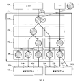
- the configuration of the API section 6 is hierarchized, and commands are transmitted in order from the upper layer to the lower layer in one direction. be done. It should be noted that not only the fifth operation example, but also the API units 6 of the first to fourth operation examples are similarly hierarchized.
- the API unit 6 has a layer on the application 15 side as an upper layer, and a layer on the control program 190 and 290 side as a lower layer. It has an internal vehicle control composite layer 17F, a simplification layer 17G, and output units 18 and 28 .
- the functions of the computing unit 17 are further subdivided into an inter-vehicle-control compounding layer 17E, an intra-vehicle-control compounding layer 17F, and a simplification layer 17G.
- the output units 18 and 28 are provided with an output unit 18C, and the control IFs 19 and 29 are provided with a control IF 19C corresponding to the output unit 18C.
- any one of the layers 17E, 17F, and 17G has one or more of the functions that the calculation unit 17 has. Further, although illustration of the input units 16 and 26 is omitted, the input units 16 and 26 are positioned in a higher layer than the vehicle control compound layer 17E.
- the inter-vehicle control compound layer 17E is the first layer in FIG. 8, that is, the top layer, and provides an abstract API that spans multiple domains related to vehicle control.
- the inter-vehicle control compound layer 17E executes the following control when receiving a request from an application using an abstract API called "driver awakening” for awakening a driver who is drowsy. have a function.
- the vehicle control composite layer 17E controls the steering vibration and sound volume to be "high (that is, change to a louder volume)" and the air conditioner cool air to "strong (that is, changes that the air volume is increased)". Run. In other words, it is control over the HMI system domain and the body system domain.
- the inter-vehicle control compound layer 17E has a function of arbitrating across domains regarding vehicle control. For example, when a control request for turning on the lights or turning on the air conditioner is received, the remaining battery capacity is referred to determine whether or not execution is possible depending on whether the remaining battery capacity is sufficient. In other words, it is arbitration across the body system domain and the power domain.
- the vehicle control compound layer 17F is the second layer in FIG. 8, that is, the second layer from the top layer, and provides an abstract API within one domain of vehicle control. For example, it provides an abstracted API called "light on in auto mode".
- the vehicle control compound layer 17F performs arbitration within the vehicle control domain. For example, when a request for "turning on lights in auto mode" and "passing" are issued at the same time, it is determined how to control. Both are abstracted APIs within the body system domain and are arbitration within the body system domain.
- the simplification layer 17G is the third layer in FIG. 8, that is, the third layer from the top layer, and has a function of hiding detailed parameters of vehicle control.
- the simplification layer 17G is configured to determine the control amount of vehicle control or the order of vehicle control. For example, a parameter designated as "High/Mid/Low” in the abstract API is converted into a specific control amount (for example, torque value). Further, for example, when "blinking for 10 seconds" is specified, a process of repeating "ON, OFF, waiting for 1 second" is executed.
- the output units 18 and 28 are layers also called base layers, which are the fourth layer in FIG. 8, that is, the fourth layer from the top layer.
- the output units 18 and 28 are configured to correspond one-to-one with the control IFs 19A-19C and 29A-29C for controlling the sensors and actuators and APIs provided by the ECUs 141-148.
- each layer 17E, 17F, 17G, 18 is set so that it is passed only to lower layers in one direction and is not passed to the same layer and upper layers.
- the inter-vehicle control compound layer 17E (In addition, the input section 16) may be added or changed.
- the application 15 can be added without changing the control programs 190 and 290 by limiting the part affected by the addition of the application 15 to a part of the API section 6 .
- One aspect of the present disclosure is to control the controlled objects 51 to 66 by transmitting commands to the control programs 190 and 290 located in the vehicle and for controlling the controlled objects 51 to 66.
- ECUs 10 to 40 configured.
- the control programs 190, 290 comprise a plurality of control IF's 19, 29 for exchanging commands.
- Each of the ECUs 10-40 includes at least one application 15, 25, a plurality of output units 18, 28, and at least one computing unit 17, 27.
- the applications 15 and 25 are configured to generate a first command that does not specify the control IFs 19 and 29 for the control programs 190 and 290 .
- the output units 18 and 28 are provided at least for each of the plurality of control IFs 19 and 29 and configured to output the input commands to the corresponding control IFs 19 and 29 .
- the calculation units 17 and 27 are configured to select the output units 18 and 28 to transmit the command from among the plurality of output units 18 and 28 based on the first command. Further, the computing units 17 and 27 generate or extract a second command, which is a command corresponding to the first command and represents a command to be transmitted to the selected output units 18 and 28, for each of the selected output units 18 and 28. configured as The calculation units 17 and 27 are configured to transmit the second command to the control IFs 19 and 29 for each of the selected output units 18 and 28 . Each of the plurality of output units 18 and 28 is configured so that there is only one output unit 18 and 28 that transmits the second command to the control IFs 19 and 29 for each of the plurality of control IFs 19 and 29. .
- the applications 15 and 25, the calculation units 17 and 27 (second command units), and the output units 18 and 28 are the applications 15 and 25, the calculation units 17 and 27, the output units 18 28 are hierarchically arranged.
- commands are configured to be transmitted in one direction according to this hierarchical order.
- the flow of commands from applications 15 and 25 to control programs 190 and 290 can be unidirectional. Therefore, the processing in the applications 15 and 25, the calculation units 17 and 27, and the output units 18 and 28 can be prevented from becoming an infinite loop.
- At least the calculation units 17 and 27 are configured to communicate with the other ECUs 10-40 and cooperate with the other ECUs 10-40 to generate the second command. According to such a configuration, the processing load of each ECU 10-40 can be reduced because the processing is distributed in cooperation with other ECUs 10-40.
- a plurality of computing units 17 and 27 are provided.
- the output units 18 and 28 (arbitration units) generate a plurality of second It is configured to arbitrate between two orders.
- the output units 18 and 28 are configured to selectively output a plurality of second commands to the control IFs 19 and 29 based on the result of arbitration.
- the calculation units 17 and 27 select the plurality of output units 18 and 28 based on one first command, and the plurality of output units 18 and 28 that select the second command configured to generate each
- the second commands for the plurality of output units 18 and 28 are generated based on one first command. can be abstracted.
- the computing units 17, 27 are configured to generate a plurality of second commands for selected output units 18, 28 based on one first command. According to such a configuration, since a plurality of second commands for the selected output units 18 and 28 are generated based on one first command, there is no need to prepare a plurality of first commands. Directives can be more abstract.
- the configuration including the engine 51, the various lights 56, the horn 61, and the power generator 66 as the controlled objects 51 to 66 has been described, but the configuration is not limited to this.
- the ECUs 10 to 40 may be configured to control these.
- the calculation unit 17 generates and transmits a plurality of second commands to the selected output units 18 and 28 based on one first command.
- the computing unit 17 may sequentially transmit a plurality of second commands.
- the order and timing of transmitting the plurality of second commands may be set in advance.
- the calculation unit 17 may transmit a plurality of second commands in order according to preset priorities.
- the computing unit 17 selects a plurality of output units 18A and 18B based on one first command, and issues a second command to these multiple output units 18A and 18B.
- a plurality of second commands may be transmitted in order according to preset priorities.
- one output unit 18, 28 is configured to transmit commands to one control IF 19, 29, but the configuration is not limited to this.
- one output section 28B may be configured to transmit commands to a plurality of control IFs 29B and 29C.
- the interface in the present disclosure includes an overall configuration that can handle multiple commands (for example, multiple control IFs 19 and 29) and a portion that handles only one type of command (for example, , part of a plurality of control IFs 19 and 29).
- each of the plurality of output units 18 and 28 has only one output unit 18 and 28 for transmitting the second command to the control IFs 19 and 29 for each of the plurality of control IFs 19 and 29. It should be configured to be The control IFs 19A-19C and 29A-29C correspond to the first input section in the present disclosure.
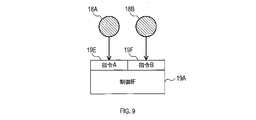
- each of the plurality of output units 18 and 28 transmits a second command to each reception unit that receives commands handled by the plurality of control IFs 19 and 29. It may be configured to be only one. Specifically, as shown in FIG. 9, the case where the control IF 19A handles commands A and B and includes a receiving unit 19E for receiving the command A and a receiving unit 19F for receiving the command B will be described.
- the reception units 19E and 19F correspond to the first input units in the present disclosure.
- the reception unit 19E is configured to receive commands only from the output unit 18A
- the reception unit 19F is configured to receive commands only from the output unit 18B.
- the relationship between the number of control interfaces 19 and 29 and the number of output units 18 and 28 is one-to-many. is set to one-to-one.
- the above configuration can be implemented as a specific configuration as shown in FIG. 10, for example.
- the vehicle service unit 107 shown in FIG. 10 has a function corresponding to the inter-vehicle control compound layer 17E, and the state management unit 108 includes the intra-vehicle control compound layer 17F, the simplification layer 17G, and the inter-vehicle control compound layer 17F. It has functions corresponding to the output units 18 and 28 .
- a vehicle control system 100 shown in FIG. 10 is mostly mounted on a vehicle and includes a plurality of ECUs 110, 115, 120, 125, 130, 141 to 148 (hereinafter, a large number of ECUs 110, etc.). Vehicle control system 100 may include center 135 outside the vehicle.
- the center 135 is configured as a server capable of providing functions to the vehicle.
- the center 135 can, for example, provide the vehicle with functions related to automatic driving or the like.
- a large number of ECUs 110, etc. and a center 135 are respectively provided with CPUs 111, 116, 121, 126, 131, 136 (hereinafter referred to as CPUs 111 to 136), semiconductor memories 112, 117, 122, 127 such as RAM, ROM, flash memory, etc. 132, 137 (hereinafter referred to as memories 112 to 137).
- the ECUs 141 to 148 also include CPUs 141A, 142A, 143A, 144A, 145A, 146A, 147A and 148A, and memories 141B, 142B, 143B, 144B, 145B, 146B, 147B and 148B, respectively.
- Controlled objects include, for example, actuators such as engines, brakes, motors, various lights, display devices, air conditioners, seats, horns, and generators, and sensors such as cameras and millimeter waves. Note that illustration of the controlled object is omitted.
- the controlled objects are individually controlled by ECUs 141 to 148, which are operation control devices.
- the ECUs 141 to 148 include an ECUF 141 having a camera control section 191, an ECUG 142 having a millimeter wave control section 192, an ECUH 143 having a brake control section 193, and an ECUI 144 having a steering control section 194. It also includes an ECUJ 145 having a display control section 195 , an ECUK 146 having a sound control section 196 , an ECUL 147 having an HVAC control section 198 , and an ECUM 148 having a seat control section 199 .
- Each control unit 191-199 has an operation control program for operating the controlled object.
- the camera control unit 191 acquires an image captured by the vehicle-mounted camera, and controls exposure and the like of the vehicle-mounted camera.
- the millimeter wave control unit 192 controls a millimeter wave radar provided in the vehicle and acquires detection results obtained by the millimeter wave radar.
- the brake control unit 193 controls the brake.
- a steering control unit 194 controls steering.
- the display control unit 195 controls indicators such as meters and warning lights.
- the sound control unit 196 controls sounds such as warning sounds and voices generated from the speaker.
- a light control unit 197 controls various lights mounted on the vehicle. Note that the light control unit 197 is provided in the ECUE 130 .
- the HVAC control unit 198 controls the in-vehicle air conditioner. HVAC stands for Heating Ventilation and Air-Conditioning.
- a seat control unit 199 controls an electric power seat of the vehicle.
- the CPUs 111 to 131 executing programs stored in non-transitional substantive recording media.
- the memories 112 to 132 correspond to non-transitional substantive recording media storing programs.
- a method corresponding to the program is executed.
- the non-transitional substantive recording medium means a recording medium excluding electromagnetic waves.
- the number of microcomputers that constitute the large number of ECUs 110 and the like and the center 135 may be one or more.
- the ECUA 110 implements functions as applications (hereinafter referred to as apps) 161 and 162, a vehicle API 171, and an athletic equipment control unit 182 by executing programs.
- apps applications
- ECUB 115 implements a function as application 163 .
- the center 135 implements functions as an application 164 .
- Applications 161 to 164 are programs for providing services to vehicle users.
- the applications 161 to 164 indirectly transmit commands to the controlled object and operate the controlled object to provide useful functions to the user.
- These applications 161 to 164 may be installed in the ECUA 110, may be installed in the ECUB 115, or may be installed in the center 135. FIG.
- the applications 161-164 are configured to generate a first command, which is a command that does not directly specify the control units 191-199 described later, to the vehicle API 171.
- the “command” includes commands such as operation requests, commands such as arguments, function calls, and the like among the data used by the vehicle API 171 .
- the "command” may include priority information indicating which command should be preferentially processed.
- the applications 161 to 164 are general-purpose programs that can support many vehicle types and grades, rather than programs created specifically for vehicle types and grades. Therefore, the applications 161 to 164 cannot specify how the vehicle in which they are mounted controls the controlled object. Therefore, the applications 161 to 164 output commands that do not specify the specific control amounts of the controlled objects, in other words, the control units 191 to 199 that the vehicle API 171 uses. On the other hand, the applications 161-164 generate desired abstract operation contents. For example, the applications 161 to 164 only instruct the operation contents to turn on the lights in the auto mode, and do not specifically include in the operation contents which lights are to be turned on.
- At least one of the applications 161 to 164 is also referred to as a service application 106 below.
- the vehicle API 171 unlike the applications 161 to 164, is a program created specifically for the vehicle type, grade, and the like. That is, the vehicle API 171 is a program that absorbs differences in vehicle types, grades, etc. so that the applications 161 to 164 do not need to be aware of the differences in vehicle types, grades, and the like.
- the vehicle API 171 is a program that functions as an API for matching commands handled by the applications 161 to 164 with commands handled by the state management unit 108 and the equipment management unit 109, which will be described later. Note that API is an abbreviation for Application Programming Interface.
- the vehicle API 171 is mounted on the ECUA 110.
- the vehicle API 171 receives commands from its own ECUA 110 , other ECUs such as the ECUB 115 , and a plurality of applications 161 to 164 installed in the center 135 .
- At least one of the vehicle APIs 171 is hereinafter also referred to as the vehicle service unit 107 .
- the vehicle service unit 107 may be provided with a plurality of vehicle APIs.
- the ECUC 20 realizes the function as the state recognition section 181.
- FIG. ECUD 25 realizes a function as HMI system state recognition section 183 .
- ECUE 130 implements a function as body system control unit 184 .
- At least one of the state recognition unit 181 , the exercise system equipment control unit 182 , the HMI system state recognition unit 183 , and the body system control unit 184 is hereinafter also referred to as the state management unit 108 .
- the state recognition unit 181, the motor system equipment control unit 182, the HMI system state recognition unit 183, and the body system control unit 184 correspond to the domains of state recognition, the motor system, the HMI system, and the body system, respectively. It is a functional part that controls the ECU to which it belongs.
- the state management unit 108 is one of the programs for controlling controlled objects.
- the state management unit 108 calculates the actuation amount of an actuator or sensor to be controlled, and sends a command including the actuation amount to various control units 191-199.
- the state management unit 108 has a function of generating a second command that embodies the first command when the abstracted first command is input.
- the vehicle service unit 107 may have the function of generating the second command that embodies the first command.
- the state management unit 108 is also a program for sending data obtained from sensors or actuators to the service application 106.
- the state management unit 108 implements a "state recognition" function and an "equipment control" function.
- the state recognition function converts sensor data or actuators obtained from the equipment management unit 109 (control units 191 to 199 to be described later) into a format suitable for the vehicle service unit 107, and transmits the converted data to the vehicle service unit 107. do.
- the equipment control function distributes drive instructions from the vehicle service unit 107 to the equipment management unit 109 .
- the state management unit 108 may be mounted in the same ECUA 110 as the vehicle API 171, or may be mounted in another ECU, the ECUC 120, the ECUD 125, or the ECUE 130.
- the state recognition unit 181 , the motor system equipment control unit 182 , the HMI system state recognition unit 183 , and the body system control unit 184 as the state management unit 108 may all be mounted on the same ECUA 110 as the vehicle API 171 . Alternatively, it may be installed in a distributed manner in each ECU that controls each domain.
- the state recognition function implements a function for classifying individual sensor raw data acquired by the equipment management unit 109 from vehicle sensors into data for each sensing target that is easy for the service application 106 to use. In addition, it implements a function of integrating data, converting it into information with a higher degree of abstraction, and transmitting it to the vehicle service section 107 .
- each control unit 191 to 199 constituting the equipment management unit 109 acquires individual information that the vehicle speed is 0 km/h, the shift position is P, and the driver is not in the vehicle. Based on this, the main focus is to indicate that the vehicle is parked. This information is further transmitted to service application 106 via vehicle service section 107 .
- the vehicle service unit 107 may combine the ack from the lights and the ack from the horn into one operation result and respond to the service application 106 .
- ack is a response to a light and horn control request.
- a car finder is a function of an application that notifies a user of the location of a vehicle such as a parking lot in an easy-to-understand manner.
- each control unit 191 to 199 for example, engine, steering, shift, door, window, air conditioner, etc.
- the equipment management unit 109 that is most suitable for realizing the vehicle operation request from the service application 106 is selected. do. Then, the data is converted into a data format that can be accepted by each of the control units 191 to 199, and distributed in consideration of the data transmission order.
- the equipment control function requests "1000Nm output to the engine, -0.1rad output to the steering request to do” is output.
- the vehicle operation request is "transition to parking state”.
- the equipment control function "Request to shift to P, request to turn off the air conditioner, request to fully close the window, request to lock the door when the request on the left is completed and the occupant is unmanned. Request to migrate" is output.
- the state management unit 108 is divided into a plurality of programs for each type of vehicle operation corresponding to the type of the first command.
- the types of vehicle motions include, for example, driving systems such as turning, running, and stopping of the vehicle, HMI systems related to information presentation to the user, body systems related to changes in the state of the body, and the like.
- the state management unit 108 is provided with management functions 81 to 84 according to the type of domain. It is stored in the memory 132 or the memory 112 of the ECUA 110, which is an integrated ECU.
- the state management unit 108 is classified not by means of implementation (for example, the control units 191 to 199) that are likely to depend on vehicle variations, but by vehicle operations that the service application 106 is likely to request.
- the state recognition unit 181 acquires information from the camera control unit 191 and the millimeter wave control unit 192 , converts it into information on the positions of vehicles and pedestrians, and outputs the information to the vehicle service unit 107 .
- the motor system equipment control unit 182 converts the vehicle operation request into control amounts for the brake control unit 193 and the steering control unit 194 and outputs the control amounts.
- the HMI system state recognition unit 183 receives a command such as an alarm, determines whether or not to perform notification using the display control unit 195 and the sound control unit 196, and outputs a control amount.
- the body system control unit 184 receives a command regarding the vehicle environment, determines which one of the light control unit 197, the HVAC control unit 198, the seat control unit 199, etc. should be operated, converts it into a suitable command, and outputs it. do.
- the architecture in the vehicle network consists of the equipment management unit 109 as the first layer, the state management unit 108 as the second layer, the vehicle service unit 107 as the third layer, and the service application 106 as the fourth layer. Configured.
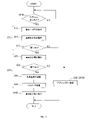
- the service application 106 transmits an operation request (that is, the first command in the present disclosure) to the vehicle service unit 107.
- the vehicle service unit 107 determines in S110 whether or not there is an operation request from the service application 106, and repeats S110 until an operation request is received. Then, if there is an operation request, the process proceeds to S10.
- the vehicle service unit 107 determines whether the operation request is accepted in S10.
- the operation request acceptance determination is a process of determining whether or not each of the control units 191 to 199 can accept the first command.
- the vehicle service unit 107 interprets the abstracted API in S12, performs arbitration within vehicle control in S14, and determines whether or not the arbitration was successful in S16. If the arbitration was successful, the process proceeds to S20, and if the arbitration was not successful, the process proceeds to S150 (or S120).
- the vehicle service unit 107 determines whether or not the first command can be accepted based on at least one of the vehicle equipment, the vehicle state, and the command syntax included in the first command. configured to The vehicle equipment and vehicle state indicate the equipment and state of the vehicle in which the vehicle control system 100 is mounted.
- the vehicle service unit 107 determines whether or not the operation request from the service application 106 can be accepted based on, for example, the following six items.
- Authentication/Authorization Whether or not the requesting service application 106 is authenticated, whether or not there is an access right to the vehicle service unit 107 ⁇ 5>
- Vehicle Abnormality of service unit 107 Whether or not an abnormality (e.g., data or communication abnormality, operation outside normal specifications, etc.) has occurred in vehicle service unit 107 ⁇ 6>>
- the number of requests that can be made within the range indicates the number of requests that are received within a predetermined period of time.
- an operation request that does not match the vehicle state is rejected. For example, while traveling at a speed of 100 km/h, the operation request to open the door is rejected.
- a determination item may be set for each vehicle API 171 in the vehicle service section 107 . In other words, there may be items for which determination is not performed.
- the memory 112 stores equipment information of the vehicle, the authentication status of the service application 106 and whether or not there is an access right, the current vehicle status related to the equipment, and the abnormality information of the vehicle and both service departments.
- the memory 112 also stores information that the vehicle service section 107 refers to when determining whether or not the vehicle can be accepted, such as cache state information.
- the vehicle service unit 107 If the vehicle service unit 107 cannot arbitrate, the vehicle service unit 107 sends an error to the service application 106 in S120 to the effect that the first command cannot be accepted.
- the state management unit 108 receives an operation request from the vehicle service unit 107 and performs operation request arbitration in S20.
- the state management unit 108 determines whether or not the first command can be accepted in consideration of competition between the first command and other commands different from the first command and the second command.
- the state management unit 108 determines whether or not the request can be received in consideration of conflict with a request received by another API (for example, another vehicle API) different from the requested API (for example, the vehicle API 171).
- the state management unit 108 performs arbitration between vehicle controls in S22, and determines in S24 whether or not the arbitration was successful. If arbitration fails, an error is sent to the service application 106 at S150. If arbitration is successful, the processing order is controlled in S26, parameter conversion is performed in S28, and the process proceeds to S160.
- the above-described operation request acceptance determination refers to the vehicle state, etc., and determines whether or not the operation request can be accepted regardless of other commands. was judged.
- the operation request arbitration of this process including “arbitration between vehicle controls” in S22) it is determined whether or not the operation request can be accepted in consideration of conflicts with other commands. Note that, when the operation request can be accepted, state management unit 108 generates a second command that embodies the abstracted first command as an operation instruction.
- the state management unit 108 determines whether or not the operation request can be accepted, for example, based on the following five items. ⁇ 1>> Request priority arbitration: Whether or not the priority of the first command is higher than requests based on other applications or user operations ⁇ 2>> Request source cancellation request: The request source requests cancellation of the request, and the request is processed ⁇ 3>> User cancel request: Whether or not an operation interruption request has been issued by the user ⁇ 4>> Request processing load overload: Whether or not the controlled target receives more requests than it can process ⁇ 5>>
- Abnormal state management unit 108/equipment management unit 109 Whether or not an abnormality (eg, data or communication abnormality, normal operation outside normal operation) has occurred in the state management unit 108 or equipment management unit 109 , The priority is specified by the application, and the operation based on the priority is determined by the receiving side. However, the receiving side may ignore the priority specified by the application.
- Request priority arbitration Whether or not the priority of the first command is higher than requests based on other
- the state management unit 108 determines that the request cannot be accepted if there is a possibility that the vehicle drive control amount that satisfies both of the requests will cause the vehicle to deviate from the road.
- priority information for requests, information about requester cancellation, information about user cancellation, and thresholds (for example, the number of requests, control amount, processing load, etc.) that can be processed by the controlled object are stored in the memory 112 or the memories 22 and 27. , 32.
- the memory 112 or the memories 22 , 27 , and 32 also store information that the state management unit 108 refers to when judging acceptance, such as abnormality information of the state management unit 108 and the equipment management unit 109 .
- the state management unit 108 outputs a second command (that is, an operation instruction) based on the first command to each control unit 191 to 199 of the equipment management unit 109 in S160.
- a second command that is, an operation instruction
- Each control unit 191 to 199 is loaded with an operation control program for operating the object to be controlled, and each control unit 191 to 199 of the equipment management unit 109 that receives the operation instruction executes the operation control program. . That is, the memory of each ECU 141-148, which is each operation control device, stores an operation control program that constitutes each control unit 191-199, and the program is executed by the CPU.
- the vehicle control system 201 of this embodiment is mounted on a vehicle.
- the vehicle may have autonomous driving capabilities in addition to manual driving capabilities.
- the vehicle may be a hybrid vehicle having an engine and an electric motor as driving sources.
- the vehicle is not limited to a vehicle having an automatic driving function and a hybrid vehicle, and may be a vehicle having only a manual driving function, or a vehicle having only an engine or only an electric motor as a drive source.
- the vehicle equipped with the vehicle control system 201 is simply referred to as a vehicle.
- the vehicle control system 201 includes one ECU 202 and multiple ECUs 203 .
- the ECU 202 integrates the plurality of ECUs 203 to achieve coordinated control of the vehicle as a whole. That is, the ECU 202 functions as an integrated ECU.
- the ECU 203 is provided for each domain divided according to the function of the vehicle, and mainly controls the multiple ECUs 4 existing within the domain. Domains are, for example, powertrain (motor system), body and chassis.
- the ECU 204 that controls the engine, the ECU 204 that controls the motor, and the ECU 204 that controls the battery are connected to the ECU 203 belonging to the power train domain.
- an ECU 204 that controls an air conditioner, an ECU 204 that controls a door, and the like are connected to the ECU 203 belonging to the domain of the body.
- the ECU 203 belonging to the chassis domain is connected to, for example, an ECU 204 that controls brakes, an ECU 204 that controls steering, and the like.
- the ECU 203 and the ECU 204 are electronic control units mainly composed of microcomputers having a CPU, a ROM, a RAM, and the like.
- the ECU 202 includes a control section 211 and an in-vehicle communication section 212 .
- the control unit 211 is an electronic control device mainly composed of a microcomputer including a CPU 221, a ROM 222, a RAM 223, and the like.
- Various functions of the microcomputer are realized by the CPU 221 executing a program stored in a non-transitional substantive recording medium.
- the ROM 222 corresponds to the non-transitional substantive recording medium storing the program.
- a method corresponding to the program is executed.
- part or all of the functions executed by the CPU 221 may be configured as hardware using one or more ICs or the like.
- the number of microcomputers constituting the control unit 211 may be one or more.
- the in-vehicle communication unit 212 is connected to the plurality of ECUs 203 via CAN or Ethernet (registered trademark), and performs data communication with the plurality of ECUs 203 .
- the vehicle control system 201 further includes an external communication device 205 .
- the vehicle-external communication device 205 performs data communication with a vehicle-external communication device via a wide-area wireless communication network.
- the vehicle-external communication device 205 is an electronic control device mainly composed of a microcomputer having a CPU, a ROM, a RAM, and the like.
- the ECU 202 performs data communication with the external communication device 205 via the internal communication unit 212 .
- the ECUs 10-40 and techniques thereof described in this disclosure are provided by configuring a processor and memory programmed to perform one or more functions embodied by a computer program. It may be implemented by a computer. Alternatively, the ECUs 10-40 and techniques described in this disclosure may be implemented by a dedicated computer provided by configuring a processor with one or more dedicated hardware logic circuits. Alternatively, the ECUs 10-40 and techniques thereof described in this disclosure are a combination of a processor and memory programmed to perform one or more functions and a processor configured by one or more hardware logic circuits. may be implemented by one or more dedicated computers configured by Computer programs may also be stored as computer-executable instructions on a computer-readable non-transitional tangible storage medium. The method of realizing the function of each part included in the ECUs 10 to 40 does not necessarily include software, and all the functions may be realized using one or more pieces of hardware.
- a plurality of functions possessed by one component in the above embodiment may be realized by a plurality of components, or a function possessed by one component may be realized by a plurality of components. . Also, a plurality of functions possessed by a plurality of components may be realized by a single component, or a function realized by a plurality of components may be realized by a single component. Also, part of the configuration of the above embodiment may be omitted. Moreover, at least part of the configuration of the above embodiment may be added or replaced with respect to the configuration of the other above embodiment.
- a vehicle control device such as the ECUs 10 to 40 that constitute the vehicle control system 1, 101, and 201, and a computer that functions as the vehicle control device.
- the present disclosure can also be implemented in various forms such as a program, a non-transitional substantive recording medium such as a semiconductor memory storing this program, and a vehicle control method.
Landscapes
- Engineering & Computer Science (AREA)
- Mechanical Engineering (AREA)
- Software Systems (AREA)
- General Engineering & Computer Science (AREA)
- Theoretical Computer Science (AREA)
- Physics & Mathematics (AREA)
- General Physics & Mathematics (AREA)
- Stored Programmes (AREA)
- Control Of Driving Devices And Active Controlling Of Vehicle (AREA)
Abstract
Description
なお、実施形態におけるECU10,20,30,40は、本開示での車両制御装置に相当し、実施形態におけるアプリケーション15A,15B,25A,25Bは、本開示での第1指令部に相当する。また、実施形態における演算部17,27は、本開示での第2指令部に相当し、実施形態における出力部18,28は、本開示での調停部に相当する。また、実施形態における制御IF19,29は、本開示でのインタフェースに相当し、実施形態におけるAPI部6は、本開示での車両制御プログラムに相当する。
[1-1.構成]
図1に示す車両制御システム1は、例えば乗用車等の車両に搭載され、複数のECU10,20,30,40(以下10~40)と、各種制御部50,55,60,65(以下50~65)と、被制御対象51,56,61,66(以下51~66)と、を備える。複数のECU10~40は、被制御対象51~66を制御するように構成される。なお、ECUは電子制御装置を表す。
上記構成を用いた第1作動例として、アプリケーション15の作動に起因して、各種ライト56を作動させる処理を、図3用いて説明する。アプリケーション15Aは、例えば、図示しない照度センサから得られる照度の値に応じて、各種ライト56に対する指令を生成する。
優先度は、例えば、第2指令の種別に応じて予め対応付けられている。例えば、ライトを点灯させる指令に対しては、優先度が相対的に低い「低」が予め対応付けられる。なお、優先度には、例えば、相対的に優先度が高い「高」、優先度が相対的に低い「低」、及び優先度が「高」と「低」との中間である「中」が準備され、第2指令はこれら何れかの優先度が対応付けられて送信される。
次に、上記構成を用いた第2作動例として、アプリケーション15の作動に起因して、各種ライト56及びホーン61を作動させる処理を、図4用いて説明する。本作動例でのアプリケーション15Aは、例えば、車両の駐車中に、ユーザが自身の車両を見つけやすくするための機能であるカーファインダを実行するよう指示を受けた場合に処理を実行する。
演算部17は、例えば、図4に示すように、複数の出力部18A及び18Bを選択する。指令を送るべき制御IF19,29に対応する指令が2種類存在するからである。出力部18Aは、例えば、各種ライト56に対する制御IF19Aに対応し、出力部18Bは、ホーン61に対応する制御IF19Bに対応する。
出力部18A及び18Bは、第2指令を受けて、制御IF19Aに第2指令を転送する。この場合、出力部18Aは、ハザードランプを制御するための第2指令を制御IF19Aに送り、出力部18Bは、ホーン61を制御するための第2指令を制御IF19Bに送る。
次に、上記構成を用いた第3作動例を、図5を用いて説明する。第3作動例は、第1作動例と大部分が同様である。ただし、演算部17が出力部18Aに加えて出力部18Bを選択すること、演算部17が出力部18Bに対する第2指令として、電力確保要求を生成し、送信する点が異なる。
演算部17は、第2指令を生成するための複数の機能を備える。第2指令を生成するための複数の機能を図6では、第1演算部17A、第2演算部17Bと表記する。
図7に示す参考例の構成では、上層である演算部17Zから下層の出力部18Zに指令が伝達され、さらに、同層の別の出力部18Yに指令が伝達され、さらにこの出力部18Yから上層である演算部17Zに指令が伝達される。
以上詳述した実施形態によれば、以下の効果を奏する。
(1a)本開示の一態様は、車両内に位置し、被制御対象51~66を制御するための制御プログラム190,290に指令を送信することで被制御対象51~66を制御するように構成されたECU10~40である。制御プログラム190,290は、指令をやりとりするための複数の制御IF19,29を備える。ECU10~40は、少なくとも1つのアプリケーション15,25と、複数の出力部18,28と、少なくとも1つの演算部17,27と、を備える。
このような構成によれば、他のECU10~40と協働し、処理を分散するため、個々のECU10~40の処理負荷を低減することができる。
このような構成によれば、1つの第1指令に基づいて、選択された出力部18,28に対する複数の第2指令を生成するので、複数の第1指令を準備する必要がなく、第1指令をより抽象化することができる。
以上、本開示の実施形態について説明したが、本開示は前述の実施形態に限定されることなく、種々変形して実施することができる。
上記の構成は、例えば、図10に示すような具体的構成として実現することができる。なお、図10で示す車両サービス部107は、前述の車両制御間複合化層17Eに対応する機能を備え、状態管理部108は、前述の車両制御内複合化層17F、簡易化層17G、及び出力部18,28に対応する機能を備える。
多数のECU110等、及びセンタ135は、それぞれ、CPU111,116,121,126,131,136(以下、CPU111~136)と、RAM、ROM、フラッシュメモリ等の半導体メモリ112,117,122,127,132,137(以下、メモリ112~137)と、を有する周知のマイクロコンピュータを中心に構成される。また、ECU141~148は、それぞれ、CPU141A,142A,143A,144A,145A,146A,147A,148A、及びメモリ141B,142B,143B,144B,145B,146B,147B,148Bを備える。
車両API171は、アプリ161~164とは異なり、車種、グレード等に特化して作成されるプログラムである。すなわち、車両API171は、アプリ161~164が車種、グレード等の相違を意識する必要がなくなるよう、車種、グレード等の相違を吸収するプログラムである。車両API171は、アプリ161~164で取り扱う指令と後述する状態管理部108及び装備管理部109で取り扱う指令とを適合させるためのAPIとして機能するプログラムである。なお、APIは、Application Programming Interfaceの略である。
ここで、ECUC20は、状態認識部181としての機能を実現する。ECUD25は、HMI系状態認識部183としての機能を実現する。ECUE130は、ボデー系制御部184としての機能を実現する。以下では、状態認識部181、運動系装備制御部182、HMI系状態認識部183、ボデー系制御部184のうちの少なくとも1つを状態管理部108とも表記する。状態認識部181、運動系装備制御部182、HMI系状態認識部183、及びボデー系制御部184は、それぞれ、状態認識、運動系、HMI系、及びボデー系というドメインに対応し、各ドメインに属するECUを統括する機能部である。
運動系装備制御部182は、車両の作動要求を、ブレーキ制御部193及びステア制御部194の制御量に変換して出力する。
ボデー系制御部184は、例えば、車両環境に関する指令を受けて、ライト制御部197、HVAC制御部198、シート制御部199等の何れか作動させるかを決定し、適合する指令に変換して出力する。
≪1≫構文:プログラム上のAPIの構文に誤りがあるか否か
≪2≫装備情報:その車両に動作させたい被制御対象が備えられているか否か
≪3≫動作可能レベル:動作させたい装備が現在動作要求を受け付け可能か否か
≪4≫認証・認可:要求元であるサービスアプリ106が認証されているか否か、車両サービス部107へのアクセス権があるか否か
≪5≫車両サービス部107の異常:車両サービス部107に異常(例えば、データや通信異常、正常規定外動作等)が発生しているか否か
≪6≫キャッシュ状態:状態管理部108にて受付不可と判定された以降、同指令について受付可能になりえる時間経過したか否か
なお、≪3≫において、「装備が受け付け可能」とは、その動作要求範囲や、一定期間内の要求可能回数が範囲内であることを表す。ただし、要求可能回数が範囲内とは、所定時間内で受けた要求の回数等を表す。また、≪3≫においては、車両状態に合致しない動作要求を拒絶する。例えば、時速100km/hでの走行中において、ドアを開ける動作要求を拒絶する。
なお、車両サービス部107における車両API171毎に、判定項目が設定されてもよい。つまり、判定を実施されない項目があってもよい。ここで、車両が備えている装備情報、サービスアプリ106の認証状態及びアクセス権の有無、装備に関係する現在の車両状態、車及び両サービス部の異常情報は、メモリ112に記憶されている。また、キャッシュ状態の情報など車両サービス部107が受付可否を判定するにあたり参照する情報も、メモリ112に記憶されている。
≪1≫要求優先度調停:他アプリやユーザ操作に基づく要求よりも第1指令の優先度が高いか否か
≪2≫要求元キャンセル要求:要求元が要求キャンセルを要求し、該要求を処理中か否か
≪3≫ユーザキャンセル要求:ユーザによる動作中断要求が発生しているか否か
≪4≫要求処理負荷オーバー:被制御対象にて処理可能な数以上の要求を受けているか否か
≪5≫状態管理部108・装備管理部109の異常:状態管理部108又は装備管理部109で異常(例えばデータや通信異常、正常規定外動作)が発生しているか否か
なお、≪1≫において、優先度はアプリに指定させ、優先度に基づく動作は受け側で判定する。ただし、受け側でアプリが指定した優先度を無視して処理してもよい。
上記の構成は、例えば、図12に示すような具体的構成として実現することもできる。この例において、本実施形態の車両制御システム201は、車両に搭載される。車両は、手動運転機能に加えて自動運転機能を有していてもよい。車両は、走行駆動源として、エンジンと電動モータとを有するハイブリッド車両であってもよい。車両は、自動運転機能を有する車両とハイブリッド車両とに限らず、手動運転機能のみを備える車両であってもよいし、走行駆動源としてエンジンのみ又は電動モータのみを有する車両であってもよい。以下では、車両制御システム201を搭載する車両を、単に車両という。
シャシドメインに属するECU203には、例えば、ブレーキを制御するECU204、及び、ステアリングを制御するECU204等が接続される。
ECU202は、制御部211と、車内通信部212とを備える。
車両制御システム201は、更に車外通信装置205を備える。車外通信装置205は、広域無線通信網を介して、車両外の通信装置との間でデータ通信を行う。車外通信装置205は、CPU、ROM及びRAM等を備えたマイクロコンピュータを中心に構成された電子制御装置である。ECU202は、車内通信部212を介して、車外通信装置205との間でデータ通信を行う。
Claims (14)
- 車両内に位置し、被制御対象(51,56,61,66)を制御するための制御プログラム(190,290)に指令を送信することで前記被制御対象を制御するように構成された車両制御装置(10,20,30,40)であって、
前記制御プログラムは、指令をやりとりするための複数のインタフェース(19A,19B,19C,29A,29B)を備え、
前記制御プログラムに対して前記インタフェースを指定しない指令である第1指令を出力するように構成された少なくとも1つの第1指令部(15A,15B,25A,25B)と、
入力された指令を対応する前記インタフェースに出力するように構成された複数の出力部(18A,18B,18C,28A,28B)と、
前記第1指令に基づいて、前記複数の出力部のうちの指令を送信させる出力部を選択し、前記第1指令に対応する指令であって、該選択した出力部に送信させる指令を表す第2指令を前記選択した出力部毎に出力することで、前記第2指令を前記インタフェースに対して送信させるように構成された少なくとも1つの第2指令部(17,27)と、
を備え、
前記複数の出力部のそれぞれは、前記複数のインタフェース毎に、該インタフェースに対して、前記第2指令を送信する前記出力部が1つのみになる
ように構成された車両制御装置。 - 請求項1に記載の車両制御装置であって、
前記第1指令部、前記第2指令部、及び前記出力部は、前記第1指令部、前記第2指令部、前記出力部の順で階層化されており、該階層の順に従って一方向に指令が伝達される
ように構成された車両制御装置。 - 請求項1又は請求項2に記載の車両制御装置であって、
少なくとも前記第2指令部は、他の車両制御装置と通信しつつ、該他の車両制御装置と協働して前記第2指令を生成する
ように構成された車両制御装置。 - 請求項1から請求項3の何れか1項に記載の車両制御装置であって、
前記第2指令部は複数備えられ、
前記複数の出力部のうちの何れかが前記複数の第2指令部にて生成された複数の第2指令を受けた場合に、前記複数の第2指令の調停を行うように構成された調停部(18,28)、をさらに備え、
前記出力部は、前記調停の結果に基づいて、前記複数の第2指令を選択的に前記インタフェースに出力する
ように構成された車両制御装置。 - 請求項1から請求項4までのいずれか1項に記載の車両制御装置であって、
前記第2指令部は、1つの前記第1指令に基づいて、複数の前記出力部を選択し、前記第2指令を前記選択した複数の出力部毎に生成する
ように構成された車両制御装置。 - 請求項1から請求項5までのいずれか1項に記載の車両制御装置であって、
前記第2指令部は、1つの前記第1指令に基づいて、前記選択された出力部に対する複数の前記第2指令を生成する
ように構成された車両制御装置。 - 車両内に位置し、被制御対象を制御するための制御プログラムに指令を送信することで前記被制御対象を制御するように構成された車両制御装置(10,20,30,40)が実行する車両制御プログラムであって、
指令をやりとりするための複数のインタフェース(19A,19B,19C,29A,29B)を備える制御プログラムに対する指令であり、かつ前記インタフェースを指定しない指令である第1指令を入力し、
入力された指令を対応する前記インタフェースに出力するように構成された複数のプログラムを複数の出力部(18A,18B,18C,28A,28B)として、
前記第1指令に基づいて、前記複数の出力部のうちの指令を送信させる出力部を選択し、前記第1指令に対応する指令であって、該選択した出力部に送信させる指令を表す第2指令を前記選択した出力部毎に前記インタフェースに対して送信させる、
機能を実現するための車両制御プログラム。 - 車両制御装置(10,20,30,40)が実行するように構成された車両制御プログラムであって、
アプリケーションからの抽象化された第1指令を受け付けるように構成された入力部(16,26)、
被制御対象を制御するための制御プログラムのインタフェースへの出力を行うように構成された複数の出力部(18,28)、
前記第1指令の具現化に必要となる前記出力部を選択し、該選択した出力部へ中間指令を送信するように構成された演算部(17,27)、
としての機能を実行し、かつ、
前記出力部は、対応する前記インタフェースを介して前記中間指令に応じた第2指令を送信し、
前記複数の出力部のそれぞれは、前記複数のインタフェース毎に、該インタフェースに対して、前記第2指令を送信する前記出力部が1つのみになる
ように設定される車両制御プログラム。 - 車両に搭載された被制御対象(51,56,61,66)を制御するように構成された複数の第1車両制御装置(50、55、60、65、141~148)と、前記複数の第1車両制御装置と通信可能に接続された第2車両制御装置(10、20、30、40、110)と、を備える車両制御システム(1)であって、
前記第1車両制御装置は、
前記第2車両制御装置から送信された指令を受け付けるように構成された複数の第1入力部(19A,19B,19C,29A,29B、19E,19F)と、
前記第1入力部により受け付けた指令に基づいて被制御対象を制御する複数の制御部(190,290)と、
を備え、
前記第2車両制御装置は、
アプリケーション(15A,15B,25A,25B)からの指令を受け付けるように構成された第2入力部(16A,16B,26A,26B)と、
前記第2入力部で受け付けたアプリケーションからの指令を処理するように構成された演算部(17,27)と、
前記演算部による処理結果に基づいて、前記第1車両制御装置への指令を出力するように構成された複数の出力部(18A,18B,28A,28B)と、を備え、
前記複数の出力部のそれぞれは、前記複数の第1入力部のそれぞれに対応し、前記出力部は対応する前記第1入力部へのみ指令を出力するよう構成される、車両制御システム。 - 請求項9に記載の車両制御システムであって、
前記第2車両制御装置は、当該第2車両制御装置が実行可能な複数の機能として、
車両制御の複数のドメインに跨る指令を処理するように構成された第1階層(17E)と、
車両制御の1つのドメイン内における指令を処理するように構成された第2階層(17F)と、
車両制御の制御量、又は車両制御の序列を決定するように構成された第3階層(17G)と、
前記出力部を有する第4階層(18A)と、
のうちの少なくとも2以上の階層を有する、車両制御システム。 - 請求項10に記載の車両制御システムであって、
前記第1階層、前記第2階層、前記第3階層、及び前記第4階層は、前記第1階層、前記第2階層、前記第3階層、前記第4階層の順で階層化されており、該階層の順に従って一方向に指令が伝達されるように構成される、車両制御システム。 - 請求項9から請求項11の何れか1項に記載の車両制御システムであって、
前記演算部は、
車両制御の複数ドメイン間で指令を調停するように構成された第1演算部(17E、108)と、
車両制御の1つのドメイン内で指令を調停するように構成された第2演算部(17F、107)と、
車両制御の制御量又は序列を決定するように構成された第3演算部(17G、108)と、
を備える、車両制御システム。 - 請求項10を引用する請求項12に記載の車両制御システムであって、
前記第2演算部は前記第2階層に含まれ、
前記第2演算部は、車両制御の各ドメインに対応して複数設けられる
車両制御システム。 - 車両に搭載された被制御対象(51,56,61,66)を制御する指令を受け付けるように構成された複数の第1入力部(19A,19B,19C,29A,29B、19E,19F)を有する複数の電子制御装置(50、55、60、65、141~148)と通信可能に接続された車両制御装置(10、20、30、40、110)であって、
アプリケーション(15A,15B,25A,25B)からの指令を受け付けるように構成された第2入力部(16A,16B,26A,26B)と、
前記第2入力部で受け付けたアプリケーションからの指令を処理するように構成された演算部(17,27)と、
前記演算部による処理結果に基づいて、前記複数の電子制御装置への指令を出力するように構成された複数の出力部(18A,18B,28A,28B)と、を備え、
前記複数の出力部のそれぞれは、前記複数の第1入力部のそれぞれに対応し、前記出力部は対応する前記第1入力部へのみ指令を出力するよう構成される、車両制御装置。
Priority Applications (5)
| Application Number | Priority Date | Filing Date | Title |
|---|---|---|---|
| CN202280040374.9A CN117425587A (zh) | 2021-06-07 | 2022-06-06 | 车辆控制装置、车辆控制程序以及车辆控制系统 |
| JP2023527854A JP7626217B2 (ja) | 2021-06-07 | 2022-06-06 | 車両制御装置、車両制御プログラム、及び車両制御システム |
| DE112022002947.1T DE112022002947T5 (de) | 2021-06-07 | 2022-06-06 | Fahrzeugsteuerungsvorrichtung, fahrzeugsteuerungsprogramm und fahrzeugsteuerungssystem |
| GB2317779.3A GB2621753A (en) | 2021-06-07 | 2022-06-06 | Vehicle control device, vehicle control program, and vehicle control system |
| US18/528,189 US20240101049A1 (en) | 2021-06-07 | 2023-12-04 | Vehicle control device, non-transitory computer-readable storage medium storing vehicle control program, and vehicle control system |
Applications Claiming Priority (2)
| Application Number | Priority Date | Filing Date | Title |
|---|---|---|---|
| JP2021-095279 | 2021-06-07 | ||
| JP2021095279 | 2021-06-07 |
Related Child Applications (1)
| Application Number | Title | Priority Date | Filing Date |
|---|---|---|---|
| US18/528,189 Continuation US20240101049A1 (en) | 2021-06-07 | 2023-12-04 | Vehicle control device, non-transitory computer-readable storage medium storing vehicle control program, and vehicle control system |
Publications (1)
| Publication Number | Publication Date |
|---|---|
| WO2022260010A1 true WO2022260010A1 (ja) | 2022-12-15 |
Family
ID=84425082
Family Applications (1)
| Application Number | Title | Priority Date | Filing Date |
|---|---|---|---|
| PCT/JP2022/022822 Ceased WO2022260010A1 (ja) | 2021-06-07 | 2022-06-06 | 車両制御装置、車両制御プログラム、及び車両制御システム |
Country Status (6)
| Country | Link |
|---|---|
| US (1) | US20240101049A1 (ja) |
| JP (1) | JP7626217B2 (ja) |
| CN (1) | CN117425587A (ja) |
| DE (1) | DE112022002947T5 (ja) |
| GB (1) | GB2621753A (ja) |
| WO (1) | WO2022260010A1 (ja) |
Cited By (3)
| Publication number | Priority date | Publication date | Assignee | Title |
|---|---|---|---|---|
| WO2024237242A1 (ja) * | 2023-05-15 | 2024-11-21 | 株式会社デンソー | 車両制御装置、及び車両制御方法 |
| WO2024237230A1 (ja) * | 2023-05-15 | 2024-11-21 | 株式会社デンソー | 車両制御システム |
| WO2024257706A1 (ja) * | 2023-06-14 | 2024-12-19 | 株式会社デンソー | 車載装置、サービス提供方法およびサービス提供プログラム |
Citations (5)
| Publication number | Priority date | Publication date | Assignee | Title |
|---|---|---|---|---|
| JP2001270399A (ja) * | 2000-03-24 | 2001-10-02 | Denso Corp | 車両用制御装置及び記録媒体 |
| WO2009093732A1 (ja) * | 2008-01-24 | 2009-07-30 | Autonetworks Technologies, Ltd. | 機器制御装置及び機器制御プログラム |
| JP2011162116A (ja) * | 2010-02-12 | 2011-08-25 | Omron Automotive Electronics Co Ltd | 制御システム |
| WO2016151743A1 (ja) * | 2015-03-24 | 2016-09-29 | 三菱電機株式会社 | 機器制御装置、車両用電子制御装置、車両用電子制御システム、機器制御方法及び機器制御プログラム |
| JP2020074191A (ja) * | 2020-01-23 | 2020-05-14 | 日立オートモティブシステムズ株式会社 | 車載処理装置 |
Family Cites Families (4)
| Publication number | Priority date | Publication date | Assignee | Title |
|---|---|---|---|---|
| JP6113538B2 (ja) * | 2012-03-23 | 2017-04-12 | 株式会社東芝 | 制御装置、制御方法、プログラムおよび半導体装置 |
| CN104272203B (zh) * | 2012-05-11 | 2016-10-12 | 三菱电机株式会社 | 控制装置以及控制方法 |
| JP7043736B2 (ja) | 2016-06-02 | 2022-03-30 | 株式会社デンソー | 車両用電子制御装置及び車両用サービス管理システム |
| JP6775662B1 (ja) | 2019-12-19 | 2020-10-28 | 株式会社Pfu | 媒体搬送装置、制御方法及び制御プログラム |
-
2022
- 2022-06-06 WO PCT/JP2022/022822 patent/WO2022260010A1/ja not_active Ceased
- 2022-06-06 GB GB2317779.3A patent/GB2621753A/en active Pending
- 2022-06-06 CN CN202280040374.9A patent/CN117425587A/zh active Pending
- 2022-06-06 JP JP2023527854A patent/JP7626217B2/ja active Active
- 2022-06-06 DE DE112022002947.1T patent/DE112022002947T5/de active Pending
-
2023
- 2023-12-04 US US18/528,189 patent/US20240101049A1/en active Pending
Patent Citations (5)
| Publication number | Priority date | Publication date | Assignee | Title |
|---|---|---|---|---|
| JP2001270399A (ja) * | 2000-03-24 | 2001-10-02 | Denso Corp | 車両用制御装置及び記録媒体 |
| WO2009093732A1 (ja) * | 2008-01-24 | 2009-07-30 | Autonetworks Technologies, Ltd. | 機器制御装置及び機器制御プログラム |
| JP2011162116A (ja) * | 2010-02-12 | 2011-08-25 | Omron Automotive Electronics Co Ltd | 制御システム |
| WO2016151743A1 (ja) * | 2015-03-24 | 2016-09-29 | 三菱電機株式会社 | 機器制御装置、車両用電子制御装置、車両用電子制御システム、機器制御方法及び機器制御プログラム |
| JP2020074191A (ja) * | 2020-01-23 | 2020-05-14 | 日立オートモティブシステムズ株式会社 | 車載処理装置 |
Cited By (3)
| Publication number | Priority date | Publication date | Assignee | Title |
|---|---|---|---|---|
| WO2024237242A1 (ja) * | 2023-05-15 | 2024-11-21 | 株式会社デンソー | 車両制御装置、及び車両制御方法 |
| WO2024237230A1 (ja) * | 2023-05-15 | 2024-11-21 | 株式会社デンソー | 車両制御システム |
| WO2024257706A1 (ja) * | 2023-06-14 | 2024-12-19 | 株式会社デンソー | 車載装置、サービス提供方法およびサービス提供プログラム |
Also Published As
| Publication number | Publication date |
|---|---|
| JP7626217B2 (ja) | 2025-02-04 |
| GB2621753A (en) | 2024-02-21 |
| JPWO2022260010A1 (ja) | 2022-12-15 |
| DE112022002947T5 (de) | 2024-04-25 |
| US20240101049A1 (en) | 2024-03-28 |
| CN117425587A (zh) | 2024-01-19 |
Similar Documents
| Publication | Publication Date | Title |
|---|---|---|
| CN113242320B (zh) | 智能驾驶系统、方法、设备及存储介质 | |
| CN112540592B (zh) | 用于确保安全的具有双自主驾驶系统的自主驾驶车辆 | |
| WO2022260010A1 (ja) | 車両制御装置、車両制御プログラム、及び車両制御システム | |
| CN112429012A (zh) | 汽车电控系统、自动驾驶控制方法及汽车 | |
| CN111071181A (zh) | 车辆仲裁系统 | |
| JP2018098733A (ja) | 車載ネットワークシステム | |
| JP7322536B2 (ja) | 移動体の制御装置 | |
| US20240380820A1 (en) | Vehicle control system, vehicle control method, and vehicle control program product | |
| US20250191038A1 (en) | Service providing system, server, on-vehicle device, storage medium storing service providing program, and service providing method | |
| CN116834744A (zh) | 计算机实现的方法、电子设备和机器可读介质 | |
| JP2020078022A (ja) | ネットワークシステム | |
| JP7794299B2 (ja) | 車両制御装置、及び車両制御システム | |
| US20240190447A1 (en) | Data provision system, vehicle control system, vehicle control device, and storage medium storing data conversion program | |
| CN120382855A (zh) | 一种自动驾驶系统及汽车 | |
| CN116691732A (zh) | 用于控制自动驾驶车辆的装置及方法 | |
| US12097890B2 (en) | Middleware software layer for vehicle autonomy subsystems | |
| US20250171036A1 (en) | Vehicle control device, inquiry method, storage medium storing program, and vehicle control system | |
| JP7852725B2 (ja) | 車両制御装置、車両制御システム、受付判定方法、及びプログラム | |
| CN115771469A (zh) | 运算装置 | |
| CN118679469A (zh) | 资源仲裁的方法和仲裁节点 | |
| US20250187554A1 (en) | Onboard device, center device, storage medium storing vehicle control program, and vehicle control method | |
| JP7816636B2 (ja) | 車両制御装置、及び車両制御方法 | |
| WO2024085010A1 (ja) | 車両の制御装置、車両制御システム、制御方法、及びプログラム | |
| JP2024105184A (ja) | 車両用制御装置及び車両用制御方法 |
Legal Events
| Date | Code | Title | Description |
|---|---|---|---|
| 121 | Ep: the epo has been informed by wipo that ep was designated in this application |
Ref document number: 22820189 Country of ref document: EP Kind code of ref document: A1 |
|
| WWE | Wipo information: entry into national phase |
Ref document number: 2023527854 Country of ref document: JP |
|
| ENP | Entry into the national phase |
Ref document number: 202317779 Country of ref document: GB Kind code of ref document: A Free format text: PCT FILING DATE = 20220606 |
|
| WWE | Wipo information: entry into national phase |
Ref document number: 2317779.3 Country of ref document: GB |
|
| WWE | Wipo information: entry into national phase |
Ref document number: 202280040374.9 Country of ref document: CN |
|
| WWE | Wipo information: entry into national phase |
Ref document number: 112022002947 Country of ref document: DE |
|
| WWP | Wipo information: published in national office |
Ref document number: 2317779.3 Country of ref document: GB |
|
| 122 | Ep: pct application non-entry in european phase |
Ref document number: 22820189 Country of ref document: EP Kind code of ref document: A1 |