WO2022259343A1 - 車両開発支援システム - Google Patents
車両開発支援システム Download PDFInfo
- Publication number
- WO2022259343A1 WO2022259343A1 PCT/JP2021/021651 JP2021021651W WO2022259343A1 WO 2022259343 A1 WO2022259343 A1 WO 2022259343A1 JP 2021021651 W JP2021021651 W JP 2021021651W WO 2022259343 A1 WO2022259343 A1 WO 2022259343A1
- Authority
- WO
- WIPO (PCT)
- Prior art keywords
- vehicle
- ecu
- real
- support system
- image
- Prior art date
- Legal status (The legal status is an assumption and is not a legal conclusion. Google has not performed a legal analysis and makes no representation as to the accuracy of the status listed.)
- Ceased
Links
Images


Classifications
-
- G—PHYSICS
- G09—EDUCATION; CRYPTOGRAPHY; DISPLAY; ADVERTISING; SEALS
- G09B—EDUCATIONAL OR DEMONSTRATION APPLIANCES; APPLIANCES FOR TEACHING, OR COMMUNICATING WITH, THE BLIND, DEAF OR MUTE; MODELS; PLANETARIA; GLOBES; MAPS; DIAGRAMS
- G09B9/00—Simulators for teaching or training purposes
- G09B9/02—Simulators for teaching or training purposes for teaching control of vehicles or other craft
- G09B9/04—Simulators for teaching or training purposes for teaching control of vehicles or other craft for teaching control of land vehicles
-
- B—PERFORMING OPERATIONS; TRANSPORTING
- B60—VEHICLES IN GENERAL
- B60K—ARRANGEMENT OR MOUNTING OF PROPULSION UNITS OR OF TRANSMISSIONS IN VEHICLES; ARRANGEMENT OR MOUNTING OF PLURAL DIVERSE PRIME-MOVERS IN VEHICLES; AUXILIARY DRIVES FOR VEHICLES; INSTRUMENTATION OR DASHBOARDS FOR VEHICLES; ARRANGEMENTS IN CONNECTION WITH COOLING, AIR INTAKE, GAS EXHAUST OR FUEL SUPPLY OF PROPULSION UNITS IN VEHICLES
- B60K35/00—Instruments specially adapted for vehicles; Arrangement of instruments in or on vehicles
- B60K35/20—Output arrangements, i.e. from vehicle to user, associated with vehicle functions or specially adapted therefor
- B60K35/21—Output arrangements, i.e. from vehicle to user, associated with vehicle functions or specially adapted therefor using visual output, e.g. blinking lights or matrix displays
- B60K35/22—Display screens
-
- B—PERFORMING OPERATIONS; TRANSPORTING
- B60—VEHICLES IN GENERAL
- B60K—ARRANGEMENT OR MOUNTING OF PROPULSION UNITS OR OF TRANSMISSIONS IN VEHICLES; ARRANGEMENT OR MOUNTING OF PLURAL DIVERSE PRIME-MOVERS IN VEHICLES; AUXILIARY DRIVES FOR VEHICLES; INSTRUMENTATION OR DASHBOARDS FOR VEHICLES; ARRANGEMENTS IN CONNECTION WITH COOLING, AIR INTAKE, GAS EXHAUST OR FUEL SUPPLY OF PROPULSION UNITS IN VEHICLES
- B60K35/00—Instruments specially adapted for vehicles; Arrangement of instruments in or on vehicles
- B60K35/20—Output arrangements, i.e. from vehicle to user, associated with vehicle functions or specially adapted therefor
- B60K35/21—Output arrangements, i.e. from vehicle to user, associated with vehicle functions or specially adapted therefor using visual output, e.g. blinking lights or matrix displays
- B60K35/23—Head-up displays [HUD]
-
- B—PERFORMING OPERATIONS; TRANSPORTING
- B60—VEHICLES IN GENERAL
- B60K—ARRANGEMENT OR MOUNTING OF PROPULSION UNITS OR OF TRANSMISSIONS IN VEHICLES; ARRANGEMENT OR MOUNTING OF PLURAL DIVERSE PRIME-MOVERS IN VEHICLES; AUXILIARY DRIVES FOR VEHICLES; INSTRUMENTATION OR DASHBOARDS FOR VEHICLES; ARRANGEMENTS IN CONNECTION WITH COOLING, AIR INTAKE, GAS EXHAUST OR FUEL SUPPLY OF PROPULSION UNITS IN VEHICLES
- B60K35/00—Instruments specially adapted for vehicles; Arrangement of instruments in or on vehicles
- B60K35/80—Arrangements for controlling instruments
-
- B—PERFORMING OPERATIONS; TRANSPORTING
- B60—VEHICLES IN GENERAL
- B60K—ARRANGEMENT OR MOUNTING OF PROPULSION UNITS OR OF TRANSMISSIONS IN VEHICLES; ARRANGEMENT OR MOUNTING OF PLURAL DIVERSE PRIME-MOVERS IN VEHICLES; AUXILIARY DRIVES FOR VEHICLES; INSTRUMENTATION OR DASHBOARDS FOR VEHICLES; ARRANGEMENTS IN CONNECTION WITH COOLING, AIR INTAKE, GAS EXHAUST OR FUEL SUPPLY OF PROPULSION UNITS IN VEHICLES
- B60K35/00—Instruments specially adapted for vehicles; Arrangement of instruments in or on vehicles
- B60K35/90—Calibration of instruments, e.g. setting initial or reference parameters; Testing of instruments, e.g. detecting malfunction
-
- B—PERFORMING OPERATIONS; TRANSPORTING
- B60—VEHICLES IN GENERAL
- B60K—ARRANGEMENT OR MOUNTING OF PROPULSION UNITS OR OF TRANSMISSIONS IN VEHICLES; ARRANGEMENT OR MOUNTING OF PLURAL DIVERSE PRIME-MOVERS IN VEHICLES; AUXILIARY DRIVES FOR VEHICLES; INSTRUMENTATION OR DASHBOARDS FOR VEHICLES; ARRANGEMENTS IN CONNECTION WITH COOLING, AIR INTAKE, GAS EXHAUST OR FUEL SUPPLY OF PROPULSION UNITS IN VEHICLES
- B60K37/00—Dashboards
-
- G—PHYSICS
- G01—MEASURING; TESTING
- G01M—TESTING STATIC OR DYNAMIC BALANCE OF MACHINES OR STRUCTURES; TESTING OF STRUCTURES OR APPARATUS, NOT OTHERWISE PROVIDED FOR
- G01M17/00—Testing of vehicles
- G01M17/007—Wheeled or endless-tracked vehicles
-
- G—PHYSICS
- G06—COMPUTING OR CALCULATING; COUNTING
- G06F—ELECTRIC DIGITAL DATA PROCESSING
- G06F3/00—Input arrangements for transferring data to be processed into a form capable of being handled by the computer; Output arrangements for transferring data from processing unit to output unit, e.g. interface arrangements
- G06F3/01—Input arrangements or combined input and output arrangements for interaction between user and computer
- G06F3/011—Arrangements for interaction with the human body, e.g. for user immersion in virtual reality
-
- G—PHYSICS
- G06—COMPUTING OR CALCULATING; COUNTING
- G06F—ELECTRIC DIGITAL DATA PROCESSING
- G06F3/00—Input arrangements for transferring data to be processed into a form capable of being handled by the computer; Output arrangements for transferring data from processing unit to output unit, e.g. interface arrangements
- G06F3/01—Input arrangements or combined input and output arrangements for interaction between user and computer
- G06F3/017—Gesture based interaction, e.g. based on a set of recognized hand gestures
-
- G—PHYSICS
- G06—COMPUTING OR CALCULATING; COUNTING
- G06F—ELECTRIC DIGITAL DATA PROCESSING
- G06F30/00—Computer-aided design [CAD]
- G06F30/20—Design optimisation, verification or simulation
-
- B—PERFORMING OPERATIONS; TRANSPORTING
- B60—VEHICLES IN GENERAL
- B60K—ARRANGEMENT OR MOUNTING OF PROPULSION UNITS OR OF TRANSMISSIONS IN VEHICLES; ARRANGEMENT OR MOUNTING OF PLURAL DIVERSE PRIME-MOVERS IN VEHICLES; AUXILIARY DRIVES FOR VEHICLES; INSTRUMENTATION OR DASHBOARDS FOR VEHICLES; ARRANGEMENTS IN CONNECTION WITH COOLING, AIR INTAKE, GAS EXHAUST OR FUEL SUPPLY OF PROPULSION UNITS IN VEHICLES
- B60K2360/00—Indexing scheme associated with groups B60K35/00 or B60K37/00 relating to details of instruments or dashboards
- B60K2360/16—Type of output information
- B60K2360/162—Visual feedback on control action
-
- B—PERFORMING OPERATIONS; TRANSPORTING
- B60—VEHICLES IN GENERAL
- B60K—ARRANGEMENT OR MOUNTING OF PROPULSION UNITS OR OF TRANSMISSIONS IN VEHICLES; ARRANGEMENT OR MOUNTING OF PLURAL DIVERSE PRIME-MOVERS IN VEHICLES; AUXILIARY DRIVES FOR VEHICLES; INSTRUMENTATION OR DASHBOARDS FOR VEHICLES; ARRANGEMENTS IN CONNECTION WITH COOLING, AIR INTAKE, GAS EXHAUST OR FUEL SUPPLY OF PROPULSION UNITS IN VEHICLES
- B60K2360/00—Indexing scheme associated with groups B60K35/00 or B60K37/00 relating to details of instruments or dashboards
- B60K2360/583—Data transfer between instruments
-
- B—PERFORMING OPERATIONS; TRANSPORTING
- B60—VEHICLES IN GENERAL
- B60Y—INDEXING SCHEME RELATING TO ASPECTS CROSS-CUTTING VEHICLE TECHNOLOGY
- B60Y2304/00—Optimising design; Manufacturing; Testing
- B60Y2304/09—Testing or calibrating during manufacturing
-
- G—PHYSICS
- G06—COMPUTING OR CALCULATING; COUNTING
- G06F—ELECTRIC DIGITAL DATA PROCESSING
- G06F30/00—Computer-aided design [CAD]
- G06F30/10—Geometric CAD
- G06F30/15—Vehicle, aircraft or watercraft design
Definitions
- the present invention relates to a vehicle development support system that supports vehicle development.
- the above-mentioned prior art aims to reduce the cost and time required for evaluation by visualizing the virtual space and the vehicle model and providing them to the evaluator.
- the arrangement and dimensions are only visually evaluated by video, and the operational feeling of the operation device cannot be evaluated by bodily sensation.
- the above-mentioned conventional technology performs driving simulation, it does not support the operation of the in-vehicle equipment and the vehicle behavior associated with the operation input of the operation device. It is difficult to properly assess behavior. For this reason, it is difficult for the conventional technology described above to evaluate the operator's feeling of operation of an operation device equivalent to a real machine together with the operation of the in-vehicle device associated with the operation.
- the present invention is to support the development of a vehicle that can evaluate the operation feeling of the operator for the operation device together with the operation of the in-vehicle equipment accompanying the operation without manufacturing the actual vehicle.
- the purpose is to provide a system.
- a visualization device for generating a video including an operation device mounted on a vehicle, and a video generated by the visualization device a virtual operating device that displays an image including the operating device that is displayed and outputs an operation signal in response to a pseudo operation input by an operator to the image of the operating device that is displayed; an ECU that outputs a signal; a real-time simulator that simulates the operation of the vehicle-mounted device according to the control signal and outputs a simulation result to the imaging device and the ECU; and a simulation result of the real-time simulator that is sent to the ECU.
- a synchronizing device for synchronizing input communication and communication for inputting the control signal to the real-time simulator, wherein the visualization device updates the image including the operation device according to the simulation result of the real-time simulator.
- the vehicle development support system it is possible to evaluate the operator's feeling of operation of the operation device together with the operation of the vehicle-mounted equipment accompanying the operation without producing an actual machine.
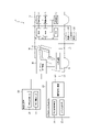
- FIG. 1 is an explanatory diagram showing the system configuration of a vehicle development support system according to an embodiment of the present invention
- FIG. FIG. 2 is a block diagram showing the signal flow of the vehicle development support system
- FIG. 2 is a block diagram showing the signal flow of the vehicle development support system
- FIG. 2 is a sequence diagram showing signal processing in one control cycle of each part in the vehicle development support system
- 1 is a block diagram showing a configuration example of a virtual operating device in a vehicle development support system
- FIG. FIG. 4 is an explanatory diagram showing an example of a pseudo operation input in the virtual space of the virtual operation device
- FIG. 11 is an explanatory diagram showing another example of pseudo operation input in the virtual space of the virtual operation device
- FIG. 4 is an explanatory diagram showing the positional relationship between the virtual space of the virtual operating device and the actual operating device;
- a vehicle development support system 1 includes an imaging device 30 that generates an image including an operation device mounted on a vehicle, and displays an image including the operation device generated by the imaging device 30, A virtual operating device 10 that outputs an operation signal corresponding to a pseudo-operation input by an operator on the displayed image of the operating device, an ECU 2 that outputs a control signal for controlling the on-vehicle device by the operation signal, and an on-vehicle device by the control signal. while simulating the operation of the real-time simulator 20 and outputting the simulation results to the imaging device 30 and the ECU 2; and a synchronizing device 4 for synchronizing, and the visualization device 30 updates the image including the operation device according to the simulation result of the real-time simulator 20 .
- the vehicle development support system 1 constructs a closed-loop system in which an operator (person) M in a cockpit C intervenes.
- a cockpit C in which an operator M boards is installed in a frame 1M.
- the vehicle development support system 1 includes an ECU (Electronic Control Unit) 2 mounted on the vehicle and onboard equipment 3 controlled by the ECU2.
- ECU Electronic Control Unit
- FIG. 1 shows an example in which a plurality of ECUs 2 and a plurality of in-vehicle devices 3 are provided.
- a plurality of ECUs 2 and a plurality of in-vehicle devices 3 are selected or all of them to be evaluated.
- a plurality of ECUs 2 in the vehicle development support system 1 are connected so as to be able to communicate with each other via a communication line L1 of an in-vehicle network (for example, CAN (Controller Area Network), etc.), like the actual vehicle.
- CAN Controller Area Network
- the vehicle development support system 1 includes a virtual operation device 10.
- the virtual operation device 10 matches the position coordinates of the operation device of the in-vehicle device 3 installed on the frame 1M with the coordinate system of the virtual space, so that the operator M can actually move the operation device installed on the frame 1M. Simulate operation of the operation device in the virtual space while touching the .
- the virtual operation device 10 corresponds to an operation device in which vehicle operation mechanisms (steering operation mechanism, accelerator operation mechanism, brake operation mechanism, shift operation mechanism, switches for operating the in-vehicle device 3) are installed on the frame 1M. and set it in the virtual space.
- vehicle operation mechanisms steering operation mechanism, accelerator operation mechanism, brake operation mechanism, shift operation mechanism, switches for operating the in-vehicle device 3
- the operating device installed on the frame 1M may be one that simulates the shape of the operating device to be mounted, and more preferably simulates the texture of the touch.
- the vehicle development support system 1 includes one or more virtual ECUs 2V as required.
- the virtual ECU2V simulates the electronic control-like behavior (electronic control function) of the real ECU when it is installed in the vehicle instead of the physical ECU (real ECU) installed in the actual vehicle. It can be configured using a general-purpose controller such as rapid control prototyping (RCP) or a PC.
- RCP rapid control prototyping
- PC general-purpose controller
- the virtual ECU 2V is one form of the ECU 2, and the ECU 2 described later includes the virtual ECU 2V unless otherwise distinguished from the real ECU.
- the vehicle development support system 1 includes a real-time simulator 20.
- the real-time simulator 20 can be configured by a computer having a plurality of processors and a memory in which programs executed by the processors are stored.
- the real-time simulator 20 calculates the physical state quantity for operating the on-vehicle device 3 based on the control signal output by the ECU 2 (real ECU) or the virtual ECU 2V, simulates the operation of the on-vehicle device 3, Simulate vehicle behavior with
- the software configuration of the real-time simulator 20 includes a vehicle motion calculation unit (vehicle motion calculation model) 21 that calculates physical state quantities of on-vehicle devices and vehicles to be controlled and outputs simulation results, and a vehicle motion calculation model that affects vehicle behavior. It has a vehicle exterior environment computation unit (vehicle environment computation model) 22 that computes the environment and reflects it in the simulation results, and an event generation unit (event generation model) 23 that generates an event in the vehicle exterior environment and reflects it in the simulation results.
- vehicle motion calculation model vehicle motion calculation model
- vehicle environment computation model vehicle environment computation model
- event generation unit event generation model
- the vehicle development support system 1 includes a visualization device 30.
- the visualization device 30 is configured by a computer that processes image information, and transmits to the virtual operation device 10 described above an image of the interior of the vehicle including an image of an operation device mounted on the actual vehicle. Also, the visualization device 30 updates the above-described image according to the simulation result by the real-time simulator 20 and transmits it to the virtual operation device 10 .
- the visualization device 30 generates image information based on the simulation result of the real-time simulator 20 and allows the operator M to view the generated image information through the virtual operation device 10.
- the processor of the visualization device 30 and a video display output unit 32 which is a program for outputting the generated video information by operating the processor of the imaging device 30 .
- the vehicle development support system 1 includes a synchronization device 4 that synchronizes communication for inputting the simulation result of the real-time simulator 20 to the ECU 2 and communication for inputting the control signal of the ECU 2 to the real-time simulator 20 .
- the synchronizer 4 is an interface that synchronously connects the communication line L1 on the ECU 2 side and the communication line L2 on the real-time simulator 20 side.
- the process of sending simulation results can be synchronized.
- One ECU 2 and another ECU 2 included in the vehicle development support system 1 are communicatively connected to each other via a communication line L1 of an in-vehicle network (eg, CAN), so that synchronous communication can be performed with each other. It is possible.
- an in-vehicle network eg, CAN
- a part of the in-vehicle device 3 to be mounted on the vehicle is arranged in the frame 1M of the vehicle development support system 1.
- the in-vehicle equipment 3 arranged in the frame 1M includes various sensors and actuators for operating the equipment.
- the vehicle development support system 1 it is possible to omit, for example, the power train system in-vehicle equipment from the frame 1M.
- the vehicle development support system 1 can deploy ECUs that control all the on-vehicle devices to be mounted on the actual vehicle, including the on-vehicle devices omitted from the frame 1M, by the ECU 2 (real ECU) and the virtual ECU 2V. .
- FIG. 2 shows a case where an on-vehicle device 3 controlled by an ECU 2 to be evaluated is arranged in a frame 1M.
- the in-vehicle device 3 here includes an actuator 3A for operating the device and a sensor 3B for detecting the operation of the actuator 3A.
- the virtual operation device 10 when the operator M performs a pseudo operation input a on the virtual operation device 10, the virtual operation device 10 inputs an operation signal b to the ECU 2 to be evaluated. Further, depending on the type of the vehicle-mounted device 3, an operation signal b is input to the vehicle-mounted device 3, thereby operating the actuator 3A, and a detection signal c of the sensor 3B detecting the operation is input to the ECU 2 as an input signal.
- the ECU 2 performs arithmetic processing according to the input signal and outputs a control signal d.
- the actuator 3A is operated by the control signal d, and the sensor 3B detects the operation and transmits the detection signal c to the ECU 2, and the ECU 2 sends a control signal based on the detection signal c.
- a closed loop is constructed that outputs d.
- the control signal d output by the ECU 2 is transmitted to the other ECU 2', and the other ECU 2' performs arithmetic processing according to the control signal d, and outputs the control signal e.
- a closed loop is formed in which the signal is sent to the ECU 2, and the ECU 2 sends a control signal d based on the control signal e to the ECU 2'.
- a control signal d is transmitted to the real-time simulator 20 via the synchronizer 4, and the real-time simulator 20 performs arithmetic processing (vehicle motion calculation processing, etc.) according to the control signal d.
- the control signal d of the ECU 2 to be evaluated is processed according to the operation signal b, the detection signal c, the control signal e, and the simulation result f, and is output. 10, the operation of the ECU 2, the operation of the in-vehicle device 3, and the operation of the other ECU 2'.
- the other ECU 2' here can be configured as an ECU 2 to which another operation signal b is input. f is transmitted, and a control signal e is transmitted to the real-time simulator 20 from another ECU 2'.
- FIG. 3 shows a case where the vehicle-mounted device controlled by the ECU 2 to be evaluated is not arranged on the frame 1M.
- the ECU 2 when the operation signal b associated with the pseudo operation input a by the operator M is input from the virtual operation device 10 to the ECU 2 to be evaluated, the ECU 2 outputs the control signal d, and the control signal d is output from the other ECU 2 ' and to the real-time simulator 20 via the synchronizer 4 .
- a closed loop is formed in which the control signal e is fed back in response to the transmission of the control signal d.
- a closed loop is constructed in which the simulation result f feeds back to the transmission of the control signal d.
- the other ECU 2' here can also be configured to receive the operation signal b and the simulation result f as described above.
- FIG. 4 shows signal processing for one control cycle of each system configuration in the vehicle development support system 1.
- the ECU 2 and the real-time simulator 20 are connected for communication via the synchronizer 4, thereby synchronizing the processing for each control cycle. That is, the ECU 2 and the real-time simulator 20 are in a state of being able to transmit and receive synchronized signals like other ECUs connected to the ECU 2 via an in-vehicle network (eg, CAN).
- an in-vehicle network eg, CAN
- the ECU 2 determines whether or not the operation signal b has been input in the previous control cycle (step S10). Skip the step and end the current control cycle.
- the ECU 2 also determines whether or not the detection signal c is input from the sensor 3B in the previous control cycle (step S12). d is calculated (step S13), and step S13 is skipped when there is no input of the detection signal c.
- the ECU 2 also determines whether or not the simulation result f has been input from the real-time simulator 20 in the previous control cycle (step S14).
- the signal d is calculated (step S15), and step S15 is skipped when the simulation result f is not input.
- the ECU 2 After calculating the control signal d in one control cycle, the ECU 2 transmits the calculated control signal d to the in-vehicle device 3 and the real-time simulator 20, and ends the processing of one control cycle.
- the in-vehicle device 3 operates the actuator 3A according to the control signal d (step S01), and the sensor 3B detects the operating state of the actuator 3A.
- a signal c is sent to the ECU 2 (step S02).
- the real-time simulator 20 determines whether or not there is a setting change in the control cycle synchronized with the processing of the ECU 2 described above (step S20). (step S21), and if there is no setting change, the initial setting or the previous setting is maintained (step S24).
- step S22 determines whether or not there is an event generation instruction.
- step S23 is skipped.
- the real-time simulator 20 determines whether or not the control signal d is received (step S25). In that case, step S26 is skipped. Then, the real-time simulator 20 transmits the simulation result f calculated in one control cycle to the ECU 2 (step S27), and ends the current control cycle.
- the ECU 2 and the real-time simulator 20 proceed with processing in mutually synchronized control cycles.
- the visualization device 30 does not necessarily perform processing in synchronization with each control cycle of the ECU 2 or the real-time simulator 20, but the control signal d output by the ECU 2 reflecting the simulation result f and the image
- the video display output of the rendering device 30 is synchronized with the input timing of the pseudo operation input a at a predetermined timing that gives a sense of realism.
- the image information generation unit 31 when the visualization device 30 receives the simulation result f transmitted from the real-time simulator 20 (step S30), the image information generation unit 31 generates image information (step S31), and outputs image display.
- the video signal is output to the virtual operating device 10 by the unit 32 (step S32).
- the video output (step S32) is performed every time the ECU 2 or the real-time simulator 20 performs a plurality of control cycles, so that the video output of the imaging device 30 can be synchronized with the output timing of the control signal d.
- the real-time simulator 20 is in a state of simulating sensors and ECUs connected to the in-vehicle network.
- the output information of sensors and ECUs which cannot be obtained unless the vehicle is actually driven, can be generated from the simulation result f of the real-time simulator 20 and put on the in-vehicle network.
- the ECU 2 and the in-vehicle equipment 3 are operated by operating the virtual operation device 10, and the operation state is reflected in the video in real time.
- the operating performance of the in-vehicle device 3 can be evaluated.
- FIG. 5 shows a configuration example of the virtual operation device 10 and the imaging device 30.
- the virtual operation device 10 includes a sensor unit 10A configured with various sensors, an information processing unit 10B configured with one or more processors, a head-mounted display 10D, and an operation device that the operator M actually touches and operates. (including an operation unit of the in-vehicle device 3, etc.).
- the operation device that the operator M actually touches and operates may generate a signal or may not generate a signal.
- the sensor unit 10A includes a line-of-sight sensor (a line-of-sight detection device 10A1) that detects the line of sight of the operator M and an input motion sensor (a motion detection device 10A2) that detects the motion of the operator M's hand. Information on the direction of the line of sight and the movement of the hand or the like is transmitted to the information processing section 10B. Note that the sensor section 10A and the head mounted display 10D can be integrated.
- the information processing section 10B includes an input action determination section 10B1 and an image generation section 10B2 as programs for processing information sent from the sensor section 10A, and corresponds to the direction in which the operator M is looking.
- An image is generated, an input image associated with movement of a hand or the like is synthesized in the image, and an input operation determination is performed to output an operation signal b from the movement.
- the operation signal b may be output based on the actual motion of the operating device installed on the frame 1M.
- the visualization device 30 has an image database 10C in addition to the above-described configuration.
- the image database 10C accumulates image data necessary for the information processing section 10B to generate an image.
- the image data includes a vehicle interior image database 10C1 in which the image of the vehicle interior of the development vehicle (vehicle interior image) can be changed in various settings, and images of various operation devices (operation device images) mounted on the development vehicle. It has an operating device image database 10C2 that allows various settings to be changed.
- the visualization device 30 updates the image according to the simulation result f of the real-time simulator 20, and at that time, takes in the image of the operation device from the image database 10C.
- the operator M By wearing the head-mounted display 10D on the head of the operator M, the operator M can visually recognize the image generated by the information processing unit 10B, and the operator M can visually recognize the virtual space.
- the operator M wears the head-mounted display 10D and visually recognizes the image generated by the information processing unit 10B. , and an input image simulating the motion of the operator M's hand or the like detected by the sensor unit 10A (motion detection device).
- the feeling of operating the physical operating device can be felt.
- the feeling of pseudo-operating the operating device displayed in the virtual space is superimposed, and the operator M feels as if he/she is actually operating the operating device in the virtual space.
- the virtual space can be displayed stereoscopically with parallax.
- the virtual space is recognized as a three-dimensional real space by the operator M, and the above-described sense of reality is heightened, so that the operator can feel as if he or she is operating a real vehicle.
- the output of the imaging device 30 described above that is, the image of the simulation result f of the real-time simulator 20 is input to the information processing section 10B of the virtual operating device 10 .
- the image of the input simulation result f is synthesized with the image of the virtual operation device 10 in correspondence with the operation signal b output from the virtual operation device 10, and is output to the head mounted display 10D.
- the image displayed on the head-mounted display 10D can only be viewed by the operator M alone. It is possible to allow a plurality of evaluators to view the image visually recognized by the user and share information for evaluation.
- the virtual operation device 10 of the vehicle development support system 1 includes the video F of the simulation result f described above, the video of the vehicle interior image G, the accelerator pedal 11, the steering wheel 12, the brake pedal 13, Images of the operation device image P such as the shift lever 14 and the center panel 15 are synthesized and displayed. Further, an input image H representing the pseudo operation input a of the operator M is displayed as a moving image matching the motion of the hand of the pseudo operation input a by being synthesized with the above-described image.
- the virtual operation device 10 when the operator M performs a pseudo-operation input a, the input image H moves in response to the pseudo-operation input a in the virtual space visually recognized by the operator M, simulating the operation. , the operation signal b is output by moving the operation device image P corresponding to the movement.
- the ECU 2 and the real-time simulator 20 are processed in mutually synchronized control cycles, and the video output of the imaging device 30 is such that a realistic feeling can be obtained with respect to the control cycle of the real-time simulator 20. Synchronization is achieved, and similarly, the image display output of the visualization device 30 and the output of the operation signal b of the virtual operation device 10 are also synchronized at a predetermined timing that gives a sense of realism.
- FIG. 6 shows an example of a pseudo operation input a in which the center panel is touched with the index finger of the left hand while operating the steering wheel 12 with the right hand.
- FIG. 7 shows an example of operating the steering wheel 12 and the shift lever 14 with the pseudo operation input a.
- a driving operation for driving the vehicle is performed by such a pseudo operation input a
- the image F of the simulation result f becomes an image simulating the vehicle behavior corresponding to the operation, as described above.
- the operator M can experience the situation of driving the vehicle by visually recognizing the image F, and at the same time, can experience the feeling of operating the mounted operating device.
- the operating device image P and the vehicle interior image G to be displayed in the virtual space can be displayed by appropriately selecting those mounted on the development vehicle from the image database 10C.
- the planning and development stage it is possible to simultaneously set the operation device and vehicle interior that affect the operation evaluation.
- the operation device image P and the vehicle interior image G are displayed as images corresponding to the line-of-sight direction of the operator M, it is possible to evaluate in the planning and development stages with more realistic images.
- FIG. 8 shows the positional relationship between the virtual space of the virtual operating device 10 and the actual operating device installed on the frame 1M.
- the positional coordinates in the virtual space match the positional coordinates of the operating device including the actual in-vehicle device 3 installed on the frame 1M.
- the positions of the images of the operation device image P such as the accelerator pedal 11, the steering wheel 12, the brake pedal 13, the shift lever 14, and the center panel 15 displayed in the virtual space are the operation positions installed on the frame 1M.
- the positions correspond to the equipment models (accelerator pedal model 11', steering wheel model 12', brake pedal model 13', shift lever model 14', and center panel model 15').
- models of the operating device as models that generate electric signals, there are an accelerator pedal model 11', a steering wheel model 12', a brake pedal model 13', and a shift lever model 14'.
- Other features include wipers, opening and closing windows, and side mirrors.
- These models can be configured with a 3D printer or the like, and may be non-moving models other than those for motion evaluation.
- the motion evaluation of the center panel 15 can be performed by the transition of images in the virtual space.
- the operation device realized in the frame 1M may be a model, so that the manufacturing time and manufacturing cost can be reduced, and the operating feeling of the model can be improved.
- HMI Human Machine Interface
- the vehicle development support system 1 As described above, according to the vehicle development support system 1 according to the embodiment of the present invention, at the planning and design stage of vehicle development, the operations of the ECU 2 and the onboard equipment 3 are evaluated, and at the same time, the operation of the vehicle under development is evaluated. It is possible to evaluate the operability of the device and the fit of the vehicle interior. As a result, it is possible to make decisions about the direction of development and identify issues at an early stage in vehicle development, thereby effectively supporting vehicle development.
Landscapes
- Engineering & Computer Science (AREA)
- Theoretical Computer Science (AREA)
- General Engineering & Computer Science (AREA)
- Physics & Mathematics (AREA)
- General Physics & Mathematics (AREA)
- Transportation (AREA)
- Chemical & Material Sciences (AREA)
- Combustion & Propulsion (AREA)
- Mechanical Engineering (AREA)
- Human Computer Interaction (AREA)
- Aviation & Aerospace Engineering (AREA)
- Business, Economics & Management (AREA)
- Educational Administration (AREA)
- Educational Technology (AREA)
- Computer Hardware Design (AREA)
- Evolutionary Computation (AREA)
- Geometry (AREA)
- Processing Or Creating Images (AREA)
Priority Applications (4)
| Application Number | Priority Date | Filing Date | Title |
|---|---|---|---|
| JP2023527186A JP7792405B2 (ja) | 2021-06-07 | 2021-06-07 | 車両開発支援システム |
| PCT/JP2021/021651 WO2022259343A1 (ja) | 2021-06-07 | 2021-06-07 | 車両開発支援システム |
| US17/925,108 US20240404422A1 (en) | 2021-06-07 | 2021-06-07 | Vehicle development support system |
| DE112021007779.1T DE112021007779T5 (de) | 2021-06-07 | 2021-06-07 | Fahrzeugentwicklungs-unterstützungssystem |
Applications Claiming Priority (1)
| Application Number | Priority Date | Filing Date | Title |
|---|---|---|---|
| PCT/JP2021/021651 WO2022259343A1 (ja) | 2021-06-07 | 2021-06-07 | 車両開発支援システム |
Publications (1)
| Publication Number | Publication Date |
|---|---|
| WO2022259343A1 true WO2022259343A1 (ja) | 2022-12-15 |
Family
ID=84424990
Family Applications (1)
| Application Number | Title | Priority Date | Filing Date |
|---|---|---|---|
| PCT/JP2021/021651 Ceased WO2022259343A1 (ja) | 2021-06-07 | 2021-06-07 | 車両開発支援システム |
Country Status (4)
| Country | Link |
|---|---|
| US (1) | US20240404422A1 (https=) |
| JP (1) | JP7792405B2 (https=) |
| DE (1) | DE112021007779T5 (https=) |
| WO (1) | WO2022259343A1 (https=) |
Families Citing this family (1)
| Publication number | Priority date | Publication date | Assignee | Title |
|---|---|---|---|---|
| EP4516558A1 (en) * | 2023-08-30 | 2025-03-05 | Harman Becker Automotive Systems GmbH | Chip architecture |
Citations (4)
| Publication number | Priority date | Publication date | Assignee | Title |
|---|---|---|---|---|
| JPH06297983A (ja) * | 1992-07-01 | 1994-10-25 | Mazda Motor Corp | 自動車の特性変更装置及び方法 |
| JP2004145685A (ja) * | 2002-10-25 | 2004-05-20 | Fujitsu Ten Ltd | シミュレ−ション装置、及び操作情報記憶方法 |
| KR20160099917A (ko) * | 2015-02-13 | 2016-08-23 | 조영철 | 운전 연습 방법 및 장치 |
| WO2021075089A1 (ja) * | 2019-10-15 | 2021-04-22 | 本田技研工業株式会社 | 車両検査システムおよび位置合わせ方法 |
Family Cites Families (5)
| Publication number | Priority date | Publication date | Assignee | Title |
|---|---|---|---|---|
| US20020052724A1 (en) * | 2000-10-23 | 2002-05-02 | Sheridan Thomas B. | Hybrid vehicle operations simulator |
| JP4666209B2 (ja) | 2005-03-29 | 2011-04-06 | マツダ株式会社 | 車両企画支援システム |
| DE102006045503A1 (de) * | 2006-09-27 | 2008-04-03 | Abb Technology Ag | System und Verfahren zur Integration von Prozessleitsystemen in eine Trainingssimulation |
| WO2008047555A1 (fr) * | 2006-09-27 | 2008-04-24 | Fujitsu Ten Limited | Dispositif de simulation, modèle de simulation et dispositif de formation de modèle de simulation |
| US20210294944A1 (en) * | 2020-03-19 | 2021-09-23 | Nvidia Corporation | Virtual environment scenarios and observers for autonomous machine applications |
-
2021
- 2021-06-07 JP JP2023527186A patent/JP7792405B2/ja active Active
- 2021-06-07 WO PCT/JP2021/021651 patent/WO2022259343A1/ja not_active Ceased
- 2021-06-07 DE DE112021007779.1T patent/DE112021007779T5/de active Pending
- 2021-06-07 US US17/925,108 patent/US20240404422A1/en active Pending
Patent Citations (4)
| Publication number | Priority date | Publication date | Assignee | Title |
|---|---|---|---|---|
| JPH06297983A (ja) * | 1992-07-01 | 1994-10-25 | Mazda Motor Corp | 自動車の特性変更装置及び方法 |
| JP2004145685A (ja) * | 2002-10-25 | 2004-05-20 | Fujitsu Ten Ltd | シミュレ−ション装置、及び操作情報記憶方法 |
| KR20160099917A (ko) * | 2015-02-13 | 2016-08-23 | 조영철 | 운전 연습 방법 및 장치 |
| WO2021075089A1 (ja) * | 2019-10-15 | 2021-04-22 | 本田技研工業株式会社 | 車両検査システムおよび位置合わせ方法 |
Non-Patent Citations (1)
| Title |
|---|
| SASAKI, SHIGERU, INDUSTRIAL SCIENCE, vol. 48, no. 5, 1 May 2016 (2016-05-01), pages 61 - 64 * |
Also Published As
| Publication number | Publication date |
|---|---|
| US20240404422A1 (en) | 2024-12-05 |
| JPWO2022259343A1 (https=) | 2022-12-15 |
| JP7792405B2 (ja) | 2025-12-25 |
| DE112021007779T5 (de) | 2024-03-28 |
Similar Documents
| Publication | Publication Date | Title |
|---|---|---|
| JP4523346B2 (ja) | ディスプレイシステム | |
| CN114896817B (zh) | 一种车辆在环融合测试系统及方法 | |
| US11797093B2 (en) | Integrating tactile nonvirtual controls in a virtual reality (VR) training simulator | |
| JP2009276996A (ja) | 情報処理装置、情報処理方法 | |
| KR20170005971A (ko) | 증강현실 기술을 이용한 특수 차량 훈련용 시뮬레이터시스템 및 그 방법 | |
| CN109643219A (zh) | 用于与在车辆中的显示设备上呈现的图像内容进行交互的方法 | |
| JP7637235B2 (ja) | 電子制御ユニットの評価装置及び評価方法 | |
| JP7792405B2 (ja) | 車両開発支援システム | |
| WO2019130919A1 (ja) | 交通流制御装置、走行シナリオのデータ構造 | |
| CN109710077B (zh) | 基于vr的虚拟物体碰撞判断方法、装置及机车实训系统 | |
| KR20170131111A (ko) | Ar 기기를 적용한 다차종 시뮬레이터 | |
| JP2007256030A (ja) | 車載カメラのキャリブレーション装置およびキャリブレーション方法 | |
| US20110060557A1 (en) | Method and system for testing a vehicle design | |
| CN113079366A (zh) | 一种4d乘坐场景模拟系统 | |
| JP2013130928A (ja) | 設計支援装置、設計支援方法及びプログラム | |
| JP7534545B2 (ja) | 車両開発支援システム | |
| Papa et al. | A new interactive railway virtual simulator for testing preventive safety | |
| KR20210133344A (ko) | 혼합 현실 체험 기구의 제어 장치 및 방법 | |
| KR20120065186A (ko) | 혼합현실 기반 자동차 디자인 검증 장치 및 방법 | |
| KR20060063187A (ko) | 핸드 인터페이스를 이용한 가상 생산 시스템 및 그 방법 | |
| KR20190079913A (ko) | 가상현실 기반으로 오토마타를 조립하고 시뮬레이션하는 장치 및 방법 | |
| JP2010134302A (ja) | 運転シミュレータのcg表示制御システムおよび方法 | |
| KR20090000901A (ko) | 체험학습시스템 | |
| US12559124B2 (en) | Driving support device | |
| EP4657139A1 (en) | System for the interactive prototyping of products, corresponding operation method and computer program product |
Legal Events
| Date | Code | Title | Description |
|---|---|---|---|
| 121 | Ep: the epo has been informed by wipo that ep was designated in this application |
Ref document number: 21945022 Country of ref document: EP Kind code of ref document: A1 |
|
| WWE | Wipo information: entry into national phase |
Ref document number: 2023527186 Country of ref document: JP |
|
| WWE | Wipo information: entry into national phase |
Ref document number: 112021007779 Country of ref document: DE |
|
| 122 | Ep: pct application non-entry in european phase |
Ref document number: 21945022 Country of ref document: EP Kind code of ref document: A1 |