WO2022259343A1 - Vehicle development support system - Google Patents
Vehicle development support system Download PDFInfo
- Publication number
- WO2022259343A1 WO2022259343A1 PCT/JP2021/021651 JP2021021651W WO2022259343A1 WO 2022259343 A1 WO2022259343 A1 WO 2022259343A1 JP 2021021651 W JP2021021651 W JP 2021021651W WO 2022259343 A1 WO2022259343 A1 WO 2022259343A1
- Authority
- WO
- WIPO (PCT)
- Prior art keywords
- vehicle
- ecu
- real
- support system
- image
- Prior art date
Links
- 238000011161 development Methods 0.000 title claims abstract description 54
- 238000004088 simulation Methods 0.000 claims abstract description 38
- 238000004891 communication Methods 0.000 claims abstract description 15
- 230000004044 response Effects 0.000 claims abstract description 5
- 230000033001 locomotion Effects 0.000 claims description 22
- 238000012800 visualization Methods 0.000 claims description 16
- 238000001514 detection method Methods 0.000 claims description 13
- 238000003384 imaging method Methods 0.000 claims description 12
- 230000035807 sensation Effects 0.000 abstract description 2
- 238000012545 processing Methods 0.000 description 12
- 230000001360 synchronised effect Effects 0.000 description 9
- 238000010586 diagram Methods 0.000 description 8
- 238000011156 evaluation Methods 0.000 description 8
- 230000010365 information processing Effects 0.000 description 7
- 238000004364 calculation method Methods 0.000 description 6
- 230000007246 mechanism Effects 0.000 description 5
- 238000004519 manufacturing process Methods 0.000 description 3
- 238000000034 method Methods 0.000 description 3
- 230000005540 biological transmission Effects 0.000 description 2
- 230000008859 change Effects 0.000 description 2
- 238000013461 design Methods 0.000 description 2
- 238000005516 engineering process Methods 0.000 description 2
- 230000006870 function Effects 0.000 description 2
- 230000008569 process Effects 0.000 description 2
- 230000001953 sensory effect Effects 0.000 description 2
- 230000009471 action Effects 0.000 description 1
- 238000012986 modification Methods 0.000 description 1
- 230000004048 modification Effects 0.000 description 1
- 238000009877 rendering Methods 0.000 description 1
- 230000007704 transition Effects 0.000 description 1
Images


Classifications
-
- G—PHYSICS
- G01—MEASURING; TESTING
- G01M—TESTING STATIC OR DYNAMIC BALANCE OF MACHINES OR STRUCTURES; TESTING OF STRUCTURES OR APPARATUS, NOT OTHERWISE PROVIDED FOR
- G01M17/00—Testing of vehicles
- G01M17/007—Wheeled or endless-tracked vehicles
-
- G—PHYSICS
- G06—COMPUTING; CALCULATING OR COUNTING
- G06T—IMAGE DATA PROCESSING OR GENERATION, IN GENERAL
- G06T19/00—Manipulating 3D models or images for computer graphics
Definitions
- the present invention relates to a vehicle development support system that supports vehicle development.
- the above-mentioned prior art aims to reduce the cost and time required for evaluation by visualizing the virtual space and the vehicle model and providing them to the evaluator.
- the arrangement and dimensions are only visually evaluated by video, and the operational feeling of the operation device cannot be evaluated by bodily sensation.
- the above-mentioned conventional technology performs driving simulation, it does not support the operation of the in-vehicle equipment and the vehicle behavior associated with the operation input of the operation device. It is difficult to properly assess behavior. For this reason, it is difficult for the conventional technology described above to evaluate the operator's feeling of operation of an operation device equivalent to a real machine together with the operation of the in-vehicle device associated with the operation.
- the present invention is to support the development of a vehicle that can evaluate the operation feeling of the operator for the operation device together with the operation of the in-vehicle equipment accompanying the operation without manufacturing the actual vehicle.
- the purpose is to provide a system.
- a visualization device for generating a video including an operation device mounted on a vehicle, and a video generated by the visualization device a virtual operating device that displays an image including the operating device that is displayed and outputs an operation signal in response to a pseudo operation input by an operator to the image of the operating device that is displayed; an ECU that outputs a signal; a real-time simulator that simulates the operation of the vehicle-mounted device according to the control signal and outputs a simulation result to the imaging device and the ECU; and a simulation result of the real-time simulator that is sent to the ECU.
- a synchronizing device for synchronizing input communication and communication for inputting the control signal to the real-time simulator, wherein the visualization device updates the image including the operation device according to the simulation result of the real-time simulator.
- the vehicle development support system it is possible to evaluate the operator's feeling of operation of the operation device together with the operation of the vehicle-mounted equipment accompanying the operation without producing an actual machine.
- FIG. 1 is an explanatory diagram showing the system configuration of a vehicle development support system according to an embodiment of the present invention
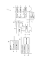
- FIG. FIG. 2 is a block diagram showing the signal flow of the vehicle development support system
- FIG. 2 is a block diagram showing the signal flow of the vehicle development support system
- FIG. 2 is a sequence diagram showing signal processing in one control cycle of each part in the vehicle development support system
- 1 is a block diagram showing a configuration example of a virtual operating device in a vehicle development support system
- FIG. FIG. 4 is an explanatory diagram showing an example of a pseudo operation input in the virtual space of the virtual operation device
- FIG. 11 is an explanatory diagram showing another example of pseudo operation input in the virtual space of the virtual operation device
- FIG. 4 is an explanatory diagram showing the positional relationship between the virtual space of the virtual operating device and the actual operating device;
- a vehicle development support system 1 includes an imaging device 30 that generates an image including an operation device mounted on a vehicle, and displays an image including the operation device generated by the imaging device 30, A virtual operating device 10 that outputs an operation signal corresponding to a pseudo-operation input by an operator on the displayed image of the operating device, an ECU 2 that outputs a control signal for controlling the on-vehicle device by the operation signal, and an on-vehicle device by the control signal. while simulating the operation of the real-time simulator 20 and outputting the simulation results to the imaging device 30 and the ECU 2; and a synchronizing device 4 for synchronizing, and the visualization device 30 updates the image including the operation device according to the simulation result of the real-time simulator 20 .
- the vehicle development support system 1 constructs a closed-loop system in which an operator (person) M in a cockpit C intervenes.
- a cockpit C in which an operator M boards is installed in a frame 1M.
- the vehicle development support system 1 includes an ECU (Electronic Control Unit) 2 mounted on the vehicle and onboard equipment 3 controlled by the ECU2.
- ECU Electronic Control Unit
- FIG. 1 shows an example in which a plurality of ECUs 2 and a plurality of in-vehicle devices 3 are provided.
- a plurality of ECUs 2 and a plurality of in-vehicle devices 3 are selected or all of them to be evaluated.
- a plurality of ECUs 2 in the vehicle development support system 1 are connected so as to be able to communicate with each other via a communication line L1 of an in-vehicle network (for example, CAN (Controller Area Network), etc.), like the actual vehicle.
- CAN Controller Area Network
- the vehicle development support system 1 includes a virtual operation device 10.
- the virtual operation device 10 matches the position coordinates of the operation device of the in-vehicle device 3 installed on the frame 1M with the coordinate system of the virtual space, so that the operator M can actually move the operation device installed on the frame 1M. Simulate operation of the operation device in the virtual space while touching the .
- the virtual operation device 10 corresponds to an operation device in which vehicle operation mechanisms (steering operation mechanism, accelerator operation mechanism, brake operation mechanism, shift operation mechanism, switches for operating the in-vehicle device 3) are installed on the frame 1M. and set it in the virtual space.
- vehicle operation mechanisms steering operation mechanism, accelerator operation mechanism, brake operation mechanism, shift operation mechanism, switches for operating the in-vehicle device 3
- the operating device installed on the frame 1M may be one that simulates the shape of the operating device to be mounted, and more preferably simulates the texture of the touch.
- the vehicle development support system 1 includes one or more virtual ECUs 2V as required.
- the virtual ECU2V simulates the electronic control-like behavior (electronic control function) of the real ECU when it is installed in the vehicle instead of the physical ECU (real ECU) installed in the actual vehicle. It can be configured using a general-purpose controller such as rapid control prototyping (RCP) or a PC.
- RCP rapid control prototyping
- PC general-purpose controller
- the virtual ECU 2V is one form of the ECU 2, and the ECU 2 described later includes the virtual ECU 2V unless otherwise distinguished from the real ECU.
- the vehicle development support system 1 includes a real-time simulator 20.
- the real-time simulator 20 can be configured by a computer having a plurality of processors and a memory in which programs executed by the processors are stored.
- the real-time simulator 20 calculates the physical state quantity for operating the on-vehicle device 3 based on the control signal output by the ECU 2 (real ECU) or the virtual ECU 2V, simulates the operation of the on-vehicle device 3, Simulate vehicle behavior with
- the software configuration of the real-time simulator 20 includes a vehicle motion calculation unit (vehicle motion calculation model) 21 that calculates physical state quantities of on-vehicle devices and vehicles to be controlled and outputs simulation results, and a vehicle motion calculation model that affects vehicle behavior. It has a vehicle exterior environment computation unit (vehicle environment computation model) 22 that computes the environment and reflects it in the simulation results, and an event generation unit (event generation model) 23 that generates an event in the vehicle exterior environment and reflects it in the simulation results.
- vehicle motion calculation model vehicle motion calculation model
- vehicle environment computation model vehicle environment computation model
- event generation unit event generation model
- the vehicle development support system 1 includes a visualization device 30.
- the visualization device 30 is configured by a computer that processes image information, and transmits to the virtual operation device 10 described above an image of the interior of the vehicle including an image of an operation device mounted on the actual vehicle. Also, the visualization device 30 updates the above-described image according to the simulation result by the real-time simulator 20 and transmits it to the virtual operation device 10 .
- the visualization device 30 generates image information based on the simulation result of the real-time simulator 20 and allows the operator M to view the generated image information through the virtual operation device 10.
- the processor of the visualization device 30 and a video display output unit 32 which is a program for outputting the generated video information by operating the processor of the imaging device 30 .
- the vehicle development support system 1 includes a synchronization device 4 that synchronizes communication for inputting the simulation result of the real-time simulator 20 to the ECU 2 and communication for inputting the control signal of the ECU 2 to the real-time simulator 20 .
- the synchronizer 4 is an interface that synchronously connects the communication line L1 on the ECU 2 side and the communication line L2 on the real-time simulator 20 side.
- the process of sending simulation results can be synchronized.
- One ECU 2 and another ECU 2 included in the vehicle development support system 1 are communicatively connected to each other via a communication line L1 of an in-vehicle network (eg, CAN), so that synchronous communication can be performed with each other. It is possible.
- an in-vehicle network eg, CAN
- a part of the in-vehicle device 3 to be mounted on the vehicle is arranged in the frame 1M of the vehicle development support system 1.
- the in-vehicle equipment 3 arranged in the frame 1M includes various sensors and actuators for operating the equipment.
- the vehicle development support system 1 it is possible to omit, for example, the power train system in-vehicle equipment from the frame 1M.
- the vehicle development support system 1 can deploy ECUs that control all the on-vehicle devices to be mounted on the actual vehicle, including the on-vehicle devices omitted from the frame 1M, by the ECU 2 (real ECU) and the virtual ECU 2V. .
- FIG. 2 shows a case where an on-vehicle device 3 controlled by an ECU 2 to be evaluated is arranged in a frame 1M.
- the in-vehicle device 3 here includes an actuator 3A for operating the device and a sensor 3B for detecting the operation of the actuator 3A.
- the virtual operation device 10 when the operator M performs a pseudo operation input a on the virtual operation device 10, the virtual operation device 10 inputs an operation signal b to the ECU 2 to be evaluated. Further, depending on the type of the vehicle-mounted device 3, an operation signal b is input to the vehicle-mounted device 3, thereby operating the actuator 3A, and a detection signal c of the sensor 3B detecting the operation is input to the ECU 2 as an input signal.
- the ECU 2 performs arithmetic processing according to the input signal and outputs a control signal d.
- the actuator 3A is operated by the control signal d, and the sensor 3B detects the operation and transmits the detection signal c to the ECU 2, and the ECU 2 sends a control signal based on the detection signal c.
- a closed loop is constructed that outputs d.
- the control signal d output by the ECU 2 is transmitted to the other ECU 2', and the other ECU 2' performs arithmetic processing according to the control signal d, and outputs the control signal e.
- a closed loop is formed in which the signal is sent to the ECU 2, and the ECU 2 sends a control signal d based on the control signal e to the ECU 2'.
- a control signal d is transmitted to the real-time simulator 20 via the synchronizer 4, and the real-time simulator 20 performs arithmetic processing (vehicle motion calculation processing, etc.) according to the control signal d.
- the control signal d of the ECU 2 to be evaluated is processed according to the operation signal b, the detection signal c, the control signal e, and the simulation result f, and is output. 10, the operation of the ECU 2, the operation of the in-vehicle device 3, and the operation of the other ECU 2'.
- the other ECU 2' here can be configured as an ECU 2 to which another operation signal b is input. f is transmitted, and a control signal e is transmitted to the real-time simulator 20 from another ECU 2'.
- FIG. 3 shows a case where the vehicle-mounted device controlled by the ECU 2 to be evaluated is not arranged on the frame 1M.
- the ECU 2 when the operation signal b associated with the pseudo operation input a by the operator M is input from the virtual operation device 10 to the ECU 2 to be evaluated, the ECU 2 outputs the control signal d, and the control signal d is output from the other ECU 2 ' and to the real-time simulator 20 via the synchronizer 4 .
- a closed loop is formed in which the control signal e is fed back in response to the transmission of the control signal d.
- a closed loop is constructed in which the simulation result f feeds back to the transmission of the control signal d.
- the other ECU 2' here can also be configured to receive the operation signal b and the simulation result f as described above.
- FIG. 4 shows signal processing for one control cycle of each system configuration in the vehicle development support system 1.
- the ECU 2 and the real-time simulator 20 are connected for communication via the synchronizer 4, thereby synchronizing the processing for each control cycle. That is, the ECU 2 and the real-time simulator 20 are in a state of being able to transmit and receive synchronized signals like other ECUs connected to the ECU 2 via an in-vehicle network (eg, CAN).
- an in-vehicle network eg, CAN
- the ECU 2 determines whether or not the operation signal b has been input in the previous control cycle (step S10). Skip the step and end the current control cycle.
- the ECU 2 also determines whether or not the detection signal c is input from the sensor 3B in the previous control cycle (step S12). d is calculated (step S13), and step S13 is skipped when there is no input of the detection signal c.
- the ECU 2 also determines whether or not the simulation result f has been input from the real-time simulator 20 in the previous control cycle (step S14).
- the signal d is calculated (step S15), and step S15 is skipped when the simulation result f is not input.
- the ECU 2 After calculating the control signal d in one control cycle, the ECU 2 transmits the calculated control signal d to the in-vehicle device 3 and the real-time simulator 20, and ends the processing of one control cycle.
- the in-vehicle device 3 operates the actuator 3A according to the control signal d (step S01), and the sensor 3B detects the operating state of the actuator 3A.
- a signal c is sent to the ECU 2 (step S02).
- the real-time simulator 20 determines whether or not there is a setting change in the control cycle synchronized with the processing of the ECU 2 described above (step S20). (step S21), and if there is no setting change, the initial setting or the previous setting is maintained (step S24).
- step S22 determines whether or not there is an event generation instruction.
- step S23 is skipped.
- the real-time simulator 20 determines whether or not the control signal d is received (step S25). In that case, step S26 is skipped. Then, the real-time simulator 20 transmits the simulation result f calculated in one control cycle to the ECU 2 (step S27), and ends the current control cycle.
- the ECU 2 and the real-time simulator 20 proceed with processing in mutually synchronized control cycles.
- the visualization device 30 does not necessarily perform processing in synchronization with each control cycle of the ECU 2 or the real-time simulator 20, but the control signal d output by the ECU 2 reflecting the simulation result f and the image
- the video display output of the rendering device 30 is synchronized with the input timing of the pseudo operation input a at a predetermined timing that gives a sense of realism.
- the image information generation unit 31 when the visualization device 30 receives the simulation result f transmitted from the real-time simulator 20 (step S30), the image information generation unit 31 generates image information (step S31), and outputs image display.
- the video signal is output to the virtual operating device 10 by the unit 32 (step S32).
- the video output (step S32) is performed every time the ECU 2 or the real-time simulator 20 performs a plurality of control cycles, so that the video output of the imaging device 30 can be synchronized with the output timing of the control signal d.
- the real-time simulator 20 is in a state of simulating sensors and ECUs connected to the in-vehicle network.
- the output information of sensors and ECUs which cannot be obtained unless the vehicle is actually driven, can be generated from the simulation result f of the real-time simulator 20 and put on the in-vehicle network.
- the ECU 2 and the in-vehicle equipment 3 are operated by operating the virtual operation device 10, and the operation state is reflected in the video in real time.
- the operating performance of the in-vehicle device 3 can be evaluated.
- FIG. 5 shows a configuration example of the virtual operation device 10 and the imaging device 30.
- the virtual operation device 10 includes a sensor unit 10A configured with various sensors, an information processing unit 10B configured with one or more processors, a head-mounted display 10D, and an operation device that the operator M actually touches and operates. (including an operation unit of the in-vehicle device 3, etc.).
- the operation device that the operator M actually touches and operates may generate a signal or may not generate a signal.
- the sensor unit 10A includes a line-of-sight sensor (a line-of-sight detection device 10A1) that detects the line of sight of the operator M and an input motion sensor (a motion detection device 10A2) that detects the motion of the operator M's hand. Information on the direction of the line of sight and the movement of the hand or the like is transmitted to the information processing section 10B. Note that the sensor section 10A and the head mounted display 10D can be integrated.
- the information processing section 10B includes an input action determination section 10B1 and an image generation section 10B2 as programs for processing information sent from the sensor section 10A, and corresponds to the direction in which the operator M is looking.
- An image is generated, an input image associated with movement of a hand or the like is synthesized in the image, and an input operation determination is performed to output an operation signal b from the movement.
- the operation signal b may be output based on the actual motion of the operating device installed on the frame 1M.
- the visualization device 30 has an image database 10C in addition to the above-described configuration.
- the image database 10C accumulates image data necessary for the information processing section 10B to generate an image.
- the image data includes a vehicle interior image database 10C1 in which the image of the vehicle interior of the development vehicle (vehicle interior image) can be changed in various settings, and images of various operation devices (operation device images) mounted on the development vehicle. It has an operating device image database 10C2 that allows various settings to be changed.
- the visualization device 30 updates the image according to the simulation result f of the real-time simulator 20, and at that time, takes in the image of the operation device from the image database 10C.
- the operator M By wearing the head-mounted display 10D on the head of the operator M, the operator M can visually recognize the image generated by the information processing unit 10B, and the operator M can visually recognize the virtual space.
- the operator M wears the head-mounted display 10D and visually recognizes the image generated by the information processing unit 10B. , and an input image simulating the motion of the operator M's hand or the like detected by the sensor unit 10A (motion detection device).
- the feeling of operating the physical operating device can be felt.
- the feeling of pseudo-operating the operating device displayed in the virtual space is superimposed, and the operator M feels as if he/she is actually operating the operating device in the virtual space.
- the virtual space can be displayed stereoscopically with parallax.
- the virtual space is recognized as a three-dimensional real space by the operator M, and the above-described sense of reality is heightened, so that the operator can feel as if he or she is operating a real vehicle.
- the output of the imaging device 30 described above that is, the image of the simulation result f of the real-time simulator 20 is input to the information processing section 10B of the virtual operating device 10 .
- the image of the input simulation result f is synthesized with the image of the virtual operation device 10 in correspondence with the operation signal b output from the virtual operation device 10, and is output to the head mounted display 10D.
- the image displayed on the head-mounted display 10D can only be viewed by the operator M alone. It is possible to allow a plurality of evaluators to view the image visually recognized by the user and share information for evaluation.
- the virtual operation device 10 of the vehicle development support system 1 includes the video F of the simulation result f described above, the video of the vehicle interior image G, the accelerator pedal 11, the steering wheel 12, the brake pedal 13, Images of the operation device image P such as the shift lever 14 and the center panel 15 are synthesized and displayed. Further, an input image H representing the pseudo operation input a of the operator M is displayed as a moving image matching the motion of the hand of the pseudo operation input a by being synthesized with the above-described image.
- the virtual operation device 10 when the operator M performs a pseudo-operation input a, the input image H moves in response to the pseudo-operation input a in the virtual space visually recognized by the operator M, simulating the operation. , the operation signal b is output by moving the operation device image P corresponding to the movement.
- the ECU 2 and the real-time simulator 20 are processed in mutually synchronized control cycles, and the video output of the imaging device 30 is such that a realistic feeling can be obtained with respect to the control cycle of the real-time simulator 20. Synchronization is achieved, and similarly, the image display output of the visualization device 30 and the output of the operation signal b of the virtual operation device 10 are also synchronized at a predetermined timing that gives a sense of realism.
- FIG. 6 shows an example of a pseudo operation input a in which the center panel is touched with the index finger of the left hand while operating the steering wheel 12 with the right hand.
- FIG. 7 shows an example of operating the steering wheel 12 and the shift lever 14 with the pseudo operation input a.
- a driving operation for driving the vehicle is performed by such a pseudo operation input a
- the image F of the simulation result f becomes an image simulating the vehicle behavior corresponding to the operation, as described above.
- the operator M can experience the situation of driving the vehicle by visually recognizing the image F, and at the same time, can experience the feeling of operating the mounted operating device.
- the operating device image P and the vehicle interior image G to be displayed in the virtual space can be displayed by appropriately selecting those mounted on the development vehicle from the image database 10C.
- the planning and development stage it is possible to simultaneously set the operation device and vehicle interior that affect the operation evaluation.
- the operation device image P and the vehicle interior image G are displayed as images corresponding to the line-of-sight direction of the operator M, it is possible to evaluate in the planning and development stages with more realistic images.
- FIG. 8 shows the positional relationship between the virtual space of the virtual operating device 10 and the actual operating device installed on the frame 1M.
- the positional coordinates in the virtual space match the positional coordinates of the operating device including the actual in-vehicle device 3 installed on the frame 1M.
- the positions of the images of the operation device image P such as the accelerator pedal 11, the steering wheel 12, the brake pedal 13, the shift lever 14, and the center panel 15 displayed in the virtual space are the operation positions installed on the frame 1M.
- the positions correspond to the equipment models (accelerator pedal model 11', steering wheel model 12', brake pedal model 13', shift lever model 14', and center panel model 15').
- models of the operating device as models that generate electric signals, there are an accelerator pedal model 11', a steering wheel model 12', a brake pedal model 13', and a shift lever model 14'.
- Other features include wipers, opening and closing windows, and side mirrors.
- These models can be configured with a 3D printer or the like, and may be non-moving models other than those for motion evaluation.
- the motion evaluation of the center panel 15 can be performed by the transition of images in the virtual space.
- the operation device realized in the frame 1M may be a model, so that the manufacturing time and manufacturing cost can be reduced, and the operating feeling of the model can be improved.
- HMI Human Machine Interface
- the vehicle development support system 1 As described above, according to the vehicle development support system 1 according to the embodiment of the present invention, at the planning and design stage of vehicle development, the operations of the ECU 2 and the onboard equipment 3 are evaluated, and at the same time, the operation of the vehicle under development is evaluated. It is possible to evaluate the operability of the device and the fit of the vehicle interior. As a result, it is possible to make decisions about the direction of development and identify issues at an early stage in vehicle development, thereby effectively supporting vehicle development.
Abstract
Provided is a vehicle development support system that makes it possible to, without producing an actual device, evaluate the operational sensation of an operator of an operation device together with the behavior of vehicle-mounted equipment accompanying the operator operation. This vehicle development support system comprises a conversion-to-video device for generating a video including an operation device to be mounted in a vehicle, a virtual operation device for displaying the video including the operation device that has been generated by the conversion-to-video device and outputting an operation signal corresponding to pseudo-operation input by an operator in relation to the displayed operation device video, an ECU for outputting a control signal for controlling vehicle-mounted equipment in response to the operation signal, a real-time simulator for simulating the behavior of the vehicle-mounted equipment according to the control signal and outputting the simulation results to the conversion-to-video device and ECU, and a synchronization device for synchronizing communication for inputting the simulation results of the real-time simulator into the ECU and communication for inputting the control signal into the real-time simulator. The conversion-to-video device updates the video including the operation device according to the simulation results of the real-time simulator.
Description
本発明は、車両の開発を支援する車両開発支援システムに関するものである。
The present invention relates to a vehicle development support system that supports vehicle development.
従来、画面上に車両モデル(外観モデルや内装モデル)を表示して、バーチャル空間内での走行シミュレーションで車両モデルを評価する車両企画支援システムが知られている(下記特許文献1参照)。
Conventionally, there is known a vehicle planning support system that displays a vehicle model (exterior model and interior model) on a screen and evaluates the vehicle model through a running simulation in a virtual space (see Patent Document 1 below).
車両に装備する操作装置は、配置状態や形態によって操作者の操作感が異なるので、その官能評価は車両開発において重要であるが、実機を各種作成して、開発の企画段階や設計段階で官能評価することはコストと時間を要する。
Since the operating feeling of the operating device installed in the vehicle differs depending on the layout and shape of the operator, sensory evaluation is important in vehicle development. Evaluation is costly and time consuming.
これに対して、前述した従来技術は、バーチャル空間と車両モデルを映像化して評価者に提供することで、評価に要するコストと時間の低減を図ってはいるが、ステアリングやペダルなどの操作装置に関しては、配置や寸法を映像で視認評価しているにすぎず、操作装置の操作感を体感して評価することはできない。また、前述した従来技術は、走行シミュレーションは行っているものの、操作装置の操作入力に伴う車載機器の動作や車両挙動のシミュレーションには対応していないため、操作装置の操作とそれに伴う車載機器の動作とを適正に評価することが難しい。このため、前述した従来技術は、実機相当の操作装置に対する操作者の操作感をその操作に伴う車載機器の動作と合わせて評価することが難しい。
On the other hand, the above-mentioned prior art aims to reduce the cost and time required for evaluation by visualizing the virtual space and the vehicle model and providing them to the evaluator. With regard to, the arrangement and dimensions are only visually evaluated by video, and the operational feeling of the operation device cannot be evaluated by bodily sensation. In addition, although the above-mentioned conventional technology performs driving simulation, it does not support the operation of the in-vehicle equipment and the vehicle behavior associated with the operation input of the operation device. It is difficult to properly assess behavior. For this reason, it is difficult for the conventional technology described above to evaluate the operator's feeling of operation of an operation device equivalent to a real machine together with the operation of the in-vehicle device associated with the operation.
本発明は、このような従来技術の課題に鑑み、実機を制作することなく、操作装置に対する操作者の操作感をその操作に伴う車載機器の動作と合わせて評価することができる車両の開発支援システムを提供することを目的とする。
In view of such problems of the prior art, the present invention is to support the development of a vehicle that can evaluate the operation feeling of the operator for the operation device together with the operation of the in-vehicle equipment accompanying the operation without manufacturing the actual vehicle. The purpose is to provide a system.
このような課題を解決するために、本発明の一実施形態における車両開発支援システムにあっては、車両に搭載される操作装置を含む映像を生成する映像化装置と、前記映像化装置で生成された前記操作装置を含む映像を表示し、表示した前記操作装置の映像に対する操作者の疑似操作入力に応じた操作信号を出力するバーチャル操作装置と、前記操作信号により、車載機器を制御する制御信号を出力するECUと、前記制御信号により、前記車載機器の動作をシミュレートすると共に、シミュレーション結果を前記映像化装置と前記ECUに出力するリアルタイムシミュレータと、前記リアルタイムシミュレータのシミュレーション結果を前記ECUに入力する通信と前記制御信号を前記リアルタイムシミュレータに入力する通信とを同期させる同期装置と、を有し、前記映像化装置は、前記リアルタイムシミュレータのシミュレーション結果に応じて前記操作装置を含む映像を更新する。
In order to solve such problems, in a vehicle development support system according to one embodiment of the present invention, a visualization device for generating a video including an operation device mounted on a vehicle, and a video generated by the visualization device a virtual operating device that displays an image including the operating device that is displayed and outputs an operation signal in response to a pseudo operation input by an operator to the image of the operating device that is displayed; an ECU that outputs a signal; a real-time simulator that simulates the operation of the vehicle-mounted device according to the control signal and outputs a simulation result to the imaging device and the ECU; and a simulation result of the real-time simulator that is sent to the ECU. a synchronizing device for synchronizing input communication and communication for inputting the control signal to the real-time simulator, wherein the visualization device updates the image including the operation device according to the simulation result of the real-time simulator. do.
本発明の一実施形態における車両開発支援システムにあっては、実機を制作することなく、操作装置に対する操作者の操作感をその操作に伴う車載機器の動作と合わせて評価することができる。
In the vehicle development support system according to one embodiment of the present invention, it is possible to evaluate the operator's feeling of operation of the operation device together with the operation of the vehicle-mounted equipment accompanying the operation without producing an actual machine.
以下、図面を参照して本発明の実施形態を説明する。以下の説明で、異なる図における同一符号は同一機能の部位を示しており、各図における重複説明は適宜省略する。
Hereinafter, embodiments of the present invention will be described with reference to the drawings. In the following description, the same reference numerals in different figures denote portions having the same function, and duplication of description in each figure will be omitted as appropriate.
本発明の実施形態に係る車両開発支援システム1は、車両に搭載される操作装置を含む映像を生成する映像化装置30と、映像化装置30で生成された操作装置を含む映像を表示し、表示した操作装置の映像に対する操作者の疑似操作入力に応じた操作信号を出力するバーチャル操作装置10と、操作信号により、車載機器を制御する制御信号を出力するECU2と、制御信号により、車載機器の動作をシミュレートすると共に、シミュレーション結果を映像化装置30とECU2に出力するリアルタイムシミュレータ20と、リアルタイムシミュレータ20のシミュレーション結果をECU2に入力する通信と制御信号をリアルタイムシミュレータ20に入力する通信とを同期させる同期装置4と、を有し、映像化装置30は、リアルタイムシミュレータ20のシミュレーション結果に応じて操作装置を含む映像を更新する。
A vehicle development support system 1 according to an embodiment of the present invention includes an imaging device 30 that generates an image including an operation device mounted on a vehicle, and displays an image including the operation device generated by the imaging device 30, A virtual operating device 10 that outputs an operation signal corresponding to a pseudo-operation input by an operator on the displayed image of the operating device, an ECU 2 that outputs a control signal for controlling the on-vehicle device by the operation signal, and an on-vehicle device by the control signal. while simulating the operation of the real-time simulator 20 and outputting the simulation results to the imaging device 30 and the ECU 2; and a synchronizing device 4 for synchronizing, and the visualization device 30 updates the image including the operation device according to the simulation result of the real-time simulator 20 .
図1に示すように、本発明の実施形態に係る車両開発支援システム1は、コックピットCに搭乗する操作者(人)Mが介在する閉ループのシステムを構築している。この車両開発支援システム1は、操作者Mが搭乗するコックピットCを枠体1Mに設置している。
As shown in FIG. 1, the vehicle development support system 1 according to the embodiment of the present invention constructs a closed-loop system in which an operator (person) M in a cockpit C intervenes. In this vehicle development support system 1, a cockpit C in which an operator M boards is installed in a frame 1M.
車両開発支援システム1は、車両に搭載されるECU(Electronic Control Unit:電子制御装置)2とECU2によって制御される車載機器3を備えている。図1に示した例では、複数のECU2と複数の車載機器3を備える例を示しているが、評価対象を特定して、単体のECU2と単体の車載機器3を備えるようにしてもよい。複数のECU2と複数の車載機器3は、その中から選択されたもの或いは全てが評価対象になる。車両開発支援システム1における複数のECU2は、実車両と同様に車載ネットワーク(例えば、CAN(Controller Area Network)など)の通信回線L1を介して相互に通信可能に接続されている。
The vehicle development support system 1 includes an ECU (Electronic Control Unit) 2 mounted on the vehicle and onboard equipment 3 controlled by the ECU2. The example shown in FIG. 1 shows an example in which a plurality of ECUs 2 and a plurality of in-vehicle devices 3 are provided. A plurality of ECUs 2 and a plurality of in-vehicle devices 3 are selected or all of them to be evaluated. A plurality of ECUs 2 in the vehicle development support system 1 are connected so as to be able to communicate with each other via a communication line L1 of an in-vehicle network (for example, CAN (Controller Area Network), etc.), like the actual vehicle.
車両開発支援システム1は、バーチャル操作装置10を備える。バーチャル操作装置10は、枠体1Mに設置された車載機器3の操作装置の位置座標をバーチャル空間の座標系と一致させることで、操作者Mが枠体1に設置されている操作装置を実際に触れながら、バーチャル空間内の操作装置を疑似操作する。
The vehicle development support system 1 includes a virtual operation device 10. The virtual operation device 10 matches the position coordinates of the operation device of the in-vehicle device 3 installed on the frame 1M with the coordinate system of the virtual space, so that the operator M can actually move the operation device installed on the frame 1M. Simulate operation of the operation device in the virtual space while touching the .
このバーチャル操作装置10によると、車両に搭載される操作装置の映像をバーチャル空間に表示して操作者Mに視認させ、現実の操作装置に対する操作に合わせたバーチャル空間内の操作装置に対する疑似操作入力で操作信号を出力する。出力された操作信号は、前述したECU2や車載機器3へ送信される。また、バーチャル操作装置10は、車両の操作機構(ステアリング操作機構、アクセル操作機構、ブレーキ操作機構、シフト操作機構、車載機器3の操作のためのスイッチ)を枠体1Mに設置した操作装置に対応してバーチャル空間に設置する。この際、枠体1Mに設置する操作装置は、搭載される操作装置の形状などが模擬されたものであればよく、手触りの質感などが模擬されていれば更に好ましい。
According to this virtual operation device 10, an image of an operation device mounted on a vehicle is displayed in a virtual space to be visually recognized by the operator M, and a pseudo operation input to the operation device in the virtual space in accordance with the operation of the real operation device is performed. to output the operation signal. The output operation signal is transmitted to the ECU 2 and the in-vehicle device 3 described above. The virtual operation device 10 corresponds to an operation device in which vehicle operation mechanisms (steering operation mechanism, accelerator operation mechanism, brake operation mechanism, shift operation mechanism, switches for operating the in-vehicle device 3) are installed on the frame 1M. and set it in the virtual space. At this time, the operating device installed on the frame 1M may be one that simulates the shape of the operating device to be mounted, and more preferably simulates the texture of the touch.
車両開発支援システム1は、必要に応じて、単数又は複数の仮想ECU2Vを備える。仮想ECU2Vは、実車両に搭載される実体物のECU(実ECU)に代わり、車両搭載時の実ECUの電子制御的な振る舞い(電子制御機能)を模擬するものであり、ラピッドコントロールプロトタイピング(rapid control prototyping:RCP)などの汎用コントローラやPCを用いて構成することができる。開発途中のECUなどをこの仮想ECU2Vで構成することにより、車両全体のECUの連携に関する評価を開発途中であっても行うことができる。仮想ECU2Vは、ECU2の一形態であり、特に実ECUと区別していない場合は、後述のECU2は仮想ECU2Vを含んでいる。
The vehicle development support system 1 includes one or more virtual ECUs 2V as required. The virtual ECU2V simulates the electronic control-like behavior (electronic control function) of the real ECU when it is installed in the vehicle instead of the physical ECU (real ECU) installed in the actual vehicle. It can be configured using a general-purpose controller such as rapid control prototyping (RCP) or a PC. By constructing the ECU under development with this virtual ECU 2V, it is possible to evaluate the cooperation of the ECUs of the entire vehicle even during development. The virtual ECU 2V is one form of the ECU 2, and the ECU 2 described later includes the virtual ECU 2V unless otherwise distinguished from the real ECU.
車両開発支援システム1は、リアルタイムシミュレータ20を備える。リアルタイムシミュレータ20は、複数のプロセッサとプロセッサによって実行されるプログラムが記憶されたメモリを備えるコンピュータによって構成することができる。リアルタイムシミュレータ20は、ECU2(実ECU)或いは仮想ECU2Vが出力する制御信号により、車載機器3を動作させる物理状態量を演算し、車載機器3の動作をシミュレートすると共に、車載機器3の動作に伴う車両挙動をシミュレートする。
The vehicle development support system 1 includes a real-time simulator 20. The real-time simulator 20 can be configured by a computer having a plurality of processors and a memory in which programs executed by the processors are stored. The real-time simulator 20 calculates the physical state quantity for operating the on-vehicle device 3 based on the control signal output by the ECU 2 (real ECU) or the virtual ECU 2V, simulates the operation of the on-vehicle device 3, Simulate vehicle behavior with
リアルタイムシミュレータ20のソフトウエア構成としては、制御対象となる車載機器及び車両の物理状態量を演算してシミュレーション結果を出力する車両運動計算部(車両運動計算モデル)21と、車両挙動に影響する車外環境を演算してシミュレーション結果に反映させる車外環境演算部(車外環境演算モデル)22と、車外環境に対してイベントを発生させてシミュレーション結果に反映させるイベント発生部(イベント発生モデル)23を備える。
The software configuration of the real-time simulator 20 includes a vehicle motion calculation unit (vehicle motion calculation model) 21 that calculates physical state quantities of on-vehicle devices and vehicles to be controlled and outputs simulation results, and a vehicle motion calculation model that affects vehicle behavior. It has a vehicle exterior environment computation unit (vehicle environment computation model) 22 that computes the environment and reflects it in the simulation results, and an event generation unit (event generation model) 23 that generates an event in the vehicle exterior environment and reflects it in the simulation results.
車両開発支援システム1は、映像化装置30を備える。映像化装置30は、映像情報を演算処理するコンピュータによって構成され、前述したバーチャル操作装置10に、実車両に搭載される操作装置の映像を含む車内の映像を送信する。また、映像化装置30は、リアルタイムシミュレータ20によるシミュレーション結果に応じ、上述の映像を更新してバーチャル操作装置10に送信する。
The vehicle development support system 1 includes a visualization device 30. The visualization device 30 is configured by a computer that processes image information, and transmits to the virtual operation device 10 described above an image of the interior of the vehicle including an image of an operation device mounted on the actual vehicle. Also, the visualization device 30 updates the above-described image according to the simulation result by the real-time simulator 20 and transmits it to the virtual operation device 10 .
映像化装置30は、リアルタイムシミュレータ20のシミュレーション結果によって映像情報を生成し、生成した映像情報を、バーチャル操作装置10を介して操作者Mに視認させるためのものであり、映像化装置30のプロセッサを動作させて映像情報を生成するプログラムである映像情報生成部31と、映像化装置30のプロセッサを動作させて生成された映像情報を出力するプログラムである映像表示出力部32を備える。
The visualization device 30 generates image information based on the simulation result of the real-time simulator 20 and allows the operator M to view the generated image information through the virtual operation device 10. The processor of the visualization device 30 and a video display output unit 32 which is a program for outputting the generated video information by operating the processor of the imaging device 30 .
車両開発支援システム1は、リアルタイムシミュレータ20のシミュレーション結果をECU2に入力する通信とECU2の制御信号をリアルタイムシミュレータ20に入力する通信とを同期させる同期装置4を備えている。
The vehicle development support system 1 includes a synchronization device 4 that synchronizes communication for inputting the simulation result of the real-time simulator 20 to the ECU 2 and communication for inputting the control signal of the ECU 2 to the real-time simulator 20 .
同期装置4は、ECU2側の通信回線L1とリアルタイムシミュレータ20側の通信回線L2を同期接続するインターフェースであり、この同期装置4を介することで、ECU2が制御信号を送信する処理とリアルタイムシミュレータ20がシミュレーション結果を送信する処理を同期させることができる。なお、車両開発支援システム1が備える1つのECU2と他のECU2とは、車載ネットワーク(例えば、CAN)の通信回線L1で互いに通信可能に接続されていることで、互いに同期した通信を行うことができるようになっている。
The synchronizer 4 is an interface that synchronously connects the communication line L1 on the ECU 2 side and the communication line L2 on the real-time simulator 20 side. The process of sending simulation results can be synchronized. One ECU 2 and another ECU 2 included in the vehicle development support system 1 are communicatively connected to each other via a communication line L1 of an in-vehicle network (eg, CAN), so that synchronous communication can be performed with each other. It is possible.
車両開発支援システム1の枠体1Mには、車両に搭載させる車載機器3の一部が配備される。枠体1Mに配備される車載機器3は、各種センサ類と機器を動作させるアクチュエータを備えている。
A part of the in-vehicle device 3 to be mounted on the vehicle is arranged in the frame 1M of the vehicle development support system 1. The in-vehicle equipment 3 arranged in the frame 1M includes various sensors and actuators for operating the equipment.
車両開発支援システム1においては、枠体1Mから、例えば、パワートレイン系の車載機器を省くことができる。しかしながら、車両開発支援システム1は、枠体1Mから省いた車載機器を含めて、実車両に搭載させる全ての車載機器を制御するECUを、ECU2(実ECU)と仮想ECU2Vによって配備させることができる。
In the vehicle development support system 1, it is possible to omit, for example, the power train system in-vehicle equipment from the frame 1M. However, the vehicle development support system 1 can deploy ECUs that control all the on-vehicle devices to be mounted on the actual vehicle, including the on-vehicle devices omitted from the frame 1M, by the ECU 2 (real ECU) and the virtual ECU 2V. .
このような車両開発支援システム1の信号の流れを説明する。図2は、評価対象のECU2に対して、そのECU2が制御する車載機器3が、枠体1Mに配備されている場合を示している。ここでの車載機器3は、機器を動作させるアクチュエータ3Aとアクチュエータ3Aの動作を検出するセンサ3Bを備える。
The signal flow of such a vehicle development support system 1 will be explained. FIG. 2 shows a case where an on-vehicle device 3 controlled by an ECU 2 to be evaluated is arranged in a frame 1M. The in-vehicle device 3 here includes an actuator 3A for operating the device and a sensor 3B for detecting the operation of the actuator 3A.
図2において、操作者Mが疑似操作入力aをバーチャル操作装置10に対して行うと、バーチャル操作装置10は、操作信号bを評価対象のECU2に入力する。また、車載機器3の種類によっては、操作信号bが車載機器3に入力され、これによってアクチュエータ3Aが動作し、その動作を検出したセンサ3Bの検出信号cが入力信号としてECU2に入力される。
In FIG. 2, when the operator M performs a pseudo operation input a on the virtual operation device 10, the virtual operation device 10 inputs an operation signal b to the ECU 2 to be evaluated. Further, depending on the type of the vehicle-mounted device 3, an operation signal b is input to the vehicle-mounted device 3, thereby operating the actuator 3A, and a detection signal c of the sensor 3B detecting the operation is input to the ECU 2 as an input signal.
ECU2は、入力された信号に応じた演算処理を行い、制御信号dを出力する。この際、ECU2と車載機器3との間では、制御信号dによってアクチュエータ3Aが動作し、その動作をセンサ3Bが検出して検出信号cをECU2に送信し、ECU2は検出信号cに基づく制御信号dを出力するという閉ループが構成される。
The ECU 2 performs arithmetic processing according to the input signal and outputs a control signal d. At this time, between the ECU 2 and the in-vehicle device 3, the actuator 3A is operated by the control signal d, and the sensor 3B detects the operation and transmits the detection signal c to the ECU 2, and the ECU 2 sends a control signal based on the detection signal c. A closed loop is constructed that outputs d.
また、ECU2と他のECU2’との間では、ECU2が出力した制御信号dが他のECU2’に送信され、他のECU2’は、制御信号dに応じた演算処理を行い、制御信号eをECU2に送信し、ECU2は制御信号eに基づく制御信号dをECU2’に送信するという閉ループが構成される。
Between the ECU 2 and the other ECU 2', the control signal d output by the ECU 2 is transmitted to the other ECU 2', and the other ECU 2' performs arithmetic processing according to the control signal d, and outputs the control signal e. A closed loop is formed in which the signal is sent to the ECU 2, and the ECU 2 sends a control signal d based on the control signal e to the ECU 2'.
そして、ECU2とリアルタイムシミュレータ20との間では、制御信号dが同期装置4を介してリアルタイムシミュレータ20に送信され、リアルタイムシミュレータ20では、制御信号dに応じた演算処理(車両運動計算処理など)が行われ、シミュレーション結果fである車載機器3や車両を動作させる物理状態量が、同期装置4を介してECU2に送信される。
Between the ECU 2 and the real-time simulator 20, a control signal d is transmitted to the real-time simulator 20 via the synchronizer 4, and the real-time simulator 20 performs arithmetic processing (vehicle motion calculation processing, etc.) according to the control signal d. A physical state quantity for operating the in-vehicle device 3 and the vehicle, which is the simulation result f, is transmitted to the ECU 2 via the synchronizer 4 .
この際、評価対象のECU2の制御信号dは、操作信号bと検出信号cと制御信号eとシミュレーション結果fに応じて演算処理されて出力され、リアルタイムシミュレータ20のシミュレーション結果fは、バーチャル操作装置10に対する操作、ECU2の動作、車載機器3の動作、他のECU2’の動作が反映したものになる。
At this time, the control signal d of the ECU 2 to be evaluated is processed according to the operation signal b, the detection signal c, the control signal e, and the simulation result f, and is output. 10, the operation of the ECU 2, the operation of the in-vehicle device 3, and the operation of the other ECU 2'.
なお、ここでの他のECU2’は、他の操作信号bが入力されるECU2として構成することができ、この際には、他のECU2’にもECU2と同様に、リアルタイムシミュレータ20のシミュレーション結果fが送信され、他のECU2’からリアルタイムシミュレータ20に制御信号eが送信される。
It should be noted that the other ECU 2' here can be configured as an ECU 2 to which another operation signal b is input. f is transmitted, and a control signal e is transmitted to the real-time simulator 20 from another ECU 2'.
図3は、評価対象のECU2が制御する車載機器が、枠体1Mに配備されていない場合を示している。この場合には、操作者Mの疑似操作入力aに伴う操作信号bがバーチャル操作装置10から評価対象のECU2に入力されると、ECU2は制御信号dを出力し、制御信号dは他のECU2’に送信されると共に同期装置4を介してリアルタイムシミュレータ20に送信される。そして、ECU2と他のECU2’との間では、前述したように、制御信号dの送信に対して制御信号eが帰還する閉ループが構成され、ECU2とリアルタイムシミュレータ20との間でも、前述したように、制御信号dの送信に対してシミュレーション結果fが帰還する閉ループが構成される。ここでの他のECU2’も、前述したように、操作信号bとシミュレーション結果fが入力される構成にすることができる。
FIG. 3 shows a case where the vehicle-mounted device controlled by the ECU 2 to be evaluated is not arranged on the frame 1M. In this case, when the operation signal b associated with the pseudo operation input a by the operator M is input from the virtual operation device 10 to the ECU 2 to be evaluated, the ECU 2 outputs the control signal d, and the control signal d is output from the other ECU 2 ' and to the real-time simulator 20 via the synchronizer 4 . Between the ECU 2 and the other ECU 2', as described above, a closed loop is formed in which the control signal e is fed back in response to the transmission of the control signal d. , a closed loop is constructed in which the simulation result f feeds back to the transmission of the control signal d. The other ECU 2' here can also be configured to receive the operation signal b and the simulation result f as described above.
図4は、車両開発支援システム1における各システム構成の1制御サイクルの信号処理を示している。ここでは、ECU2とリアルタイムシミュレータ20は、同期装置4を介して通信接続されることで、制御サイクル毎の処理が同期している。すなわち、ECU2とリアルタイムシミュレータ20は、ECU2と車載ネットワーク(例えばCAN)を介して接続されている他のECUと同様に、同期した信号の送受信が可能な状態になっている。
FIG. 4 shows signal processing for one control cycle of each system configuration in the vehicle development support system 1. FIG. Here, the ECU 2 and the real-time simulator 20 are connected for communication via the synchronizer 4, thereby synchronizing the processing for each control cycle. That is, the ECU 2 and the real-time simulator 20 are in a state of being able to transmit and receive synchronized signals like other ECUs connected to the ECU 2 via an in-vehicle network (eg, CAN).
ECU2は、各制御サイクルにおいて、前回の制御サイクルで操作信号bの入力があるか否かの判断を行い(ステップS10)、前回の制御サイクルで操作信号bの入力が無い場合には、以下のステップをスキップして、今回の制御サイクルを終了する。
In each control cycle, the ECU 2 determines whether or not the operation signal b has been input in the previous control cycle (step S10). Skip the step and end the current control cycle.
またECU2は、前回の制御サイクルでセンサ3Bからの検出信号cの入力があるか否かの判断を行い(ステップS12)、検出信号cの入力がある場合には、検出信号cに基づく制御信号dを算出し(ステップS13)、検出信号cの入力が無い場合には、ステップS13をスキップする。
The ECU 2 also determines whether or not the detection signal c is input from the sensor 3B in the previous control cycle (step S12). d is calculated (step S13), and step S13 is skipped when there is no input of the detection signal c.
またECU2は、前回の制御サイクルでリアルタイムシミュレータ20からのシミュレーション結果fの入力があるか否かの判断を行い(ステップS14)、シミュレーション結果fの入力がある場合には、シミュレーション結果fに基づく制御信号dを算出し(ステップS15)、シミュレーション結果fの入力が無い場合には、ステップS15をスキップする。
The ECU 2 also determines whether or not the simulation result f has been input from the real-time simulator 20 in the previous control cycle (step S14). The signal d is calculated (step S15), and step S15 is skipped when the simulation result f is not input.
そして、ECU2は、1制御サイクルでの制御信号dの算出がなされると、算出した制御信号dを車載機器3とリアルタイムシミュレータ20に送信し、1制御サイクルの処理を終了する。
After calculating the control signal d in one control cycle, the ECU 2 transmits the calculated control signal d to the in-vehicle device 3 and the real-time simulator 20, and ends the processing of one control cycle.
これに対して、車載機器3は、制御信号dがECU2から送信されると、制御信号dに応じてアクチュエータ3Aを作動させ(ステップS01)、アクチュエータ3Aの作動状態をセンサ3Bで検出して検出信号cをECU2に送信する(ステップS02)。
On the other hand, when the control signal d is transmitted from the ECU 2, the in-vehicle device 3 operates the actuator 3A according to the control signal d (step S01), and the sensor 3B detects the operating state of the actuator 3A. A signal c is sent to the ECU 2 (step S02).
一方、リアルタイムシミュレータ20は、前述したECU2の処理と同期した制御サイクルにおいて、設定変更の有無を判断し(ステップS20)、設定変更が有る場合には、車外環境演算部22にて車外環境演算処理を行い(ステップS21)、設定変更が無い場合には、初期設定或いは前回設定の維持がなされる(ステップS24)。
On the other hand, the real-time simulator 20 determines whether or not there is a setting change in the control cycle synchronized with the processing of the ECU 2 described above (step S20). (step S21), and if there is no setting change, the initial setting or the previous setting is maintained (step S24).
次に、リアルタイムシミュレータ20は、イベント発生指示の有無が判断され(ステップS22)、イベント発生指示がある場合には、イベント発生の演算処理がなされ(ステップS23)、イベント発生指示が無い場合には、ステップS23がスキップされる。
Next, the real-time simulator 20 determines whether or not there is an event generation instruction (step S22). , step S23 is skipped.
また、リアルタイムシミュレータ20は、制御信号dの受信の有無が判断され(ステップS25)、受信している場合には、制御信号dに応じた車両運動計算を行い(ステップS26)、受信していない場合には、ステップS26がスキップされる。そして、リアルタイムシミュレータ20は、1つの制御サイクルで演算処理したシミュレーション結果fをECU2に送信して(ステップS27)、今回の制御サイクルを終了する。
Also, the real-time simulator 20 determines whether or not the control signal d is received (step S25). In that case, step S26 is skipped. Then, the real-time simulator 20 transmits the simulation result f calculated in one control cycle to the ECU 2 (step S27), and ends the current control cycle.
このように、ECU2とリアルタイムシミュレータ20は、互いに同期した制御サイクルで処理が進められる。これに対して、映像化装置30は、必ずしもECU2やリアルタイムシミュレータ20の各制御サイクルに同期した処理はなされなくてもよいが、シミュレーション結果fを反映してECU2が出力する制御信号dと、映像化装置30の映像表示出力とを、疑似操作入力aの入力タイミングに対してリアル感が得られる程度の所定タイミングで同期させる。
In this way, the ECU 2 and the real-time simulator 20 proceed with processing in mutually synchronized control cycles. On the other hand, the visualization device 30 does not necessarily perform processing in synchronization with each control cycle of the ECU 2 or the real-time simulator 20, but the control signal d output by the ECU 2 reflecting the simulation result f and the image The video display output of the rendering device 30 is synchronized with the input timing of the pseudo operation input a at a predetermined timing that gives a sense of realism.
具体的には、映像化装置30は、リアルタイムシミュレータ20から送信されたシミュレーション結果fを受信すると(ステップS30)、映像情報生成部31にて映像情報の生成を行い(ステップS31)、映像表示出力部32にてバーチャル操作装置10へ映像信号を出力する(ステップS32)。この際、映像出力(ステップS32)をECU2やリアルタイムシミュレータ20の制御サイクルを複数回行う毎に実施することで、映像化装置30の映像出力を制御信号dの出力タイミングに同期させることができる。
Specifically, when the visualization device 30 receives the simulation result f transmitted from the real-time simulator 20 (step S30), the image information generation unit 31 generates image information (step S31), and outputs image display. The video signal is output to the virtual operating device 10 by the unit 32 (step S32). At this time, the video output (step S32) is performed every time the ECU 2 or the real-time simulator 20 performs a plurality of control cycles, so that the video output of the imaging device 30 can be synchronized with the output timing of the control signal d.
このような構成の車両開発支援システム1によると、同期装置4を介してECU2とリアルタイムシミュレータ20を接続することで、リアルタイムシミュレータ20は、車載ネットワークに接続されるセンサやECUを模擬した状態になり、実際に車両を走行させないと得ることができないセンサやECUの出力情報を、リアルタイムシミュレータ20のシミュレーション結果fで生成して車載ネットワークに乗せることができる。これによって、実際に車両が走行している状況を模擬して、バーチャル操作装置10の操作でECU2や車載機器3を動作させ、その動作状態をリアルタイムで映像に反映させ、映像を観ながらECU2や車載機器3の動作性能を評価することができる。
According to the vehicle development support system 1 having such a configuration, by connecting the ECU 2 and the real-time simulator 20 via the synchronization device 4, the real-time simulator 20 is in a state of simulating sensors and ECUs connected to the in-vehicle network. The output information of sensors and ECUs, which cannot be obtained unless the vehicle is actually driven, can be generated from the simulation result f of the real-time simulator 20 and put on the in-vehicle network. In this way, a situation in which the vehicle is actually running is simulated, and the ECU 2 and the in-vehicle equipment 3 are operated by operating the virtual operation device 10, and the operation state is reflected in the video in real time. The operating performance of the in-vehicle device 3 can be evaluated.
図5に、バーチャル操作装置10と映像化装置30の構成例を示す。バーチャル操作装置10は、各種センサによって構成されるセンサ部10Aと、単数又は複数のプロセッサで構成される情報処理部10Bと、ヘッドマウントディスプレイ10Dと、操作者Mが実際に触れて操作する操作装置(車載機器3の操作部などを含む)とを備える。操作者Mが実際に触れて操作する操作装置は、信号を発生させるものであってよいし、信号を発生させないものであってもよい。
FIG. 5 shows a configuration example of the virtual operation device 10 and the imaging device 30. The virtual operation device 10 includes a sensor unit 10A configured with various sensors, an information processing unit 10B configured with one or more processors, a head-mounted display 10D, and an operation device that the operator M actually touches and operates. (including an operation unit of the in-vehicle device 3, etc.). The operation device that the operator M actually touches and operates may generate a signal or may not generate a signal.
センサ部10Aは、操作者Mの視線を検出する視線センサ(視線検出装置10A1)と操作者Mの手などの動きを検出する入力動作センサ(動作検出装置10A2)などを備え、操作者Mの視線の向きと手などの動きの情報を情報処理部10Bに送信する。なお、センサ部10Aとヘッドマウントディスプレイ10Dは一体構成にすることができる。
The sensor unit 10A includes a line-of-sight sensor (a line-of-sight detection device 10A1) that detects the line of sight of the operator M and an input motion sensor (a motion detection device 10A2) that detects the motion of the operator M's hand. Information on the direction of the line of sight and the movement of the hand or the like is transmitted to the information processing section 10B. Note that the sensor section 10A and the head mounted display 10D can be integrated.
情報処理部10Bは、センサ部10Aから送られてきた情報を演算処理するプログラムとして、入力動作判定部10B1と映像生成部10B2を備えており、操作者Mの視線が向いている方向に対応する映像を生成すると共に、その映像の中に手などの動きに伴う入力画像を合成して、その動きから操作信号bを出力する入力動作判定を行う。なお、ここでは、映像の動きから操作信号bを出力する例を示したが、枠体1Mに設置される実際の操作装置の動きによって操作信号bを出力するようにしてもよい。
The information processing section 10B includes an input action determination section 10B1 and an image generation section 10B2 as programs for processing information sent from the sensor section 10A, and corresponds to the direction in which the operator M is looking. An image is generated, an input image associated with movement of a hand or the like is synthesized in the image, and an input operation determination is performed to output an operation signal b from the movement. Although an example of outputting the operation signal b based on the motion of the image is shown here, the operation signal b may be output based on the actual motion of the operating device installed on the frame 1M.
映像化装置30は、前述した構成に加えて、画像データベース10Cを備える。画像データベース10Cは、情報処理部10Bが映像を生成するために必要な画像データを蓄積している。この画像データとしては、開発車両の車両内装の画像(車両内装画像)を様々に設定変更できるようにした車両内装画像データベース10C1と、開発車両が搭載する各種操作装置の画像(操作装置画像)を様々に設定変更できるようにした操作装置画像データベース10C2を備えている。映像化装置30は、前述したように、リアルタイムシミュレータ20のシミュレーション結果fに応じて映像を更新するが、その際画像データベース10Cから操作装置の映像を取り込む。
The visualization device 30 has an image database 10C in addition to the above-described configuration. The image database 10C accumulates image data necessary for the information processing section 10B to generate an image. The image data includes a vehicle interior image database 10C1 in which the image of the vehicle interior of the development vehicle (vehicle interior image) can be changed in various settings, and images of various operation devices (operation device images) mounted on the development vehicle. It has an operating device image database 10C2 that allows various settings to be changed. As described above, the visualization device 30 updates the image according to the simulation result f of the real-time simulator 20, and at that time, takes in the image of the operation device from the image database 10C.
ヘッドマウントディスプレイ10Dは、操作者Mの頭部に装着することで、操作者に情報処理部10Bが生成する映像を視認させ、操作者Mにバーチャル空間を視認させる。操作者Mは、ヘッドマウントディスプレイ10Dを装着して、情報処理部10Bが生成した映像を視認することで、バーチャル空間の中に、開発車両に装備される操作装置の映像と開発車両の車両内装の映像を視認すると共に、センサ部10A(動作検出装置)で検出された操作者Mの手などの動きを模擬した入力画像を視認する。
By wearing the head-mounted display 10D on the head of the operator M, the operator M can visually recognize the image generated by the information processing unit 10B, and the operator M can visually recognize the virtual space. The operator M wears the head-mounted display 10D and visually recognizes the image generated by the information processing unit 10B. , and an input image simulating the motion of the operator M's hand or the like detected by the sensor unit 10A (motion detection device).
この際、ヘッドマウントディスプレイ10Dに表示されるバーチャル空間の映像は、コックピットC周りに設置されている実体のある操作装置と同じ空間座標になっているので、実体のある操作装置を操作する感覚が、バーチャル空間に表示されている操作装置を疑似操作する感覚に重なることになり、操作者Mは、バーチャル空間の操作装置を実際に操作している感覚になる。ここで、バーチャル空間の表示は、視差を設けて立体視できることが好ましい。これによりバーチャル空間が3次元の実空間として操作者Mに認識され、前述した感覚の現実感が高くなるので、実車に乗り込んで操作しているような感覚が得られる。
At this time, since the image of the virtual space displayed on the head-mounted display 10D has the same spatial coordinates as the physical operating device installed around the cockpit C, the feeling of operating the physical operating device can be felt. , the feeling of pseudo-operating the operating device displayed in the virtual space is superimposed, and the operator M feels as if he/she is actually operating the operating device in the virtual space. Here, it is preferable that the virtual space can be displayed stereoscopically with parallax. As a result, the virtual space is recognized as a three-dimensional real space by the operator M, and the above-described sense of reality is heightened, so that the operator can feel as if he or she is operating a real vehicle.
そして、バーチャル操作装置10の情報処理部10Bには、前述した映像化装置30の出力、すなわち、リアルタイムシミュレータ20のシミュレーション結果fの映像が入力される。入力されたシミュレーション結果fの映像は、バーチャル操作装置10が出力する操作信号bに対応させてバーチャル操作装置10の映像に合成され、ヘッドマウントディスプレイ10Dに出力される。
Then, the output of the imaging device 30 described above, that is, the image of the simulation result f of the real-time simulator 20 is input to the information processing section 10B of the virtual operating device 10 . The image of the input simulation result f is synthesized with the image of the virtual operation device 10 in correspondence with the operation signal b output from the virtual operation device 10, and is output to the head mounted display 10D.
この際、ヘッドマウントディスプレイ10Dに表示させる映像は、操作者M一人しか視認することができないが、ヘッドマウントディスプレイ10Dに表示させる映像をフラットパネルディスプレイなどのディスプレイ33に表示することで、操作者Mが視認している映像を複数人の評価者に視認させ、評価のための情報を共有させることができる。
At this time, the image displayed on the head-mounted display 10D can only be viewed by the operator M alone. It is possible to allow a plurality of evaluators to view the image visually recognized by the user and share information for evaluation.
車両開発支援システム1のバーチャル操作装置10には、図6に示すように、前述したシミュレーション結果fの映像Fと、車両内装画像Gの映像と、アクセルペタル11、ステアリングホイール12、ブレーキペタル13、シフトレバー14、センターパネル15などの操作装置画像Pの映像が合成されて表示される。また、操作者Mの疑似操作入力aを示す入力画像Hが、疑似操作入力aの手の動きに合わせた動きのある映像として、前述した映像に合成して表示される。
As shown in FIG. 6, the virtual operation device 10 of the vehicle development support system 1 includes the video F of the simulation result f described above, the video of the vehicle interior image G, the accelerator pedal 11, the steering wheel 12, the brake pedal 13, Images of the operation device image P such as the shift lever 14 and the center panel 15 are synthesized and displayed. Further, an input image H representing the pseudo operation input a of the operator M is displayed as a moving image matching the motion of the hand of the pseudo operation input a by being synthesized with the above-described image.
このバーチャル操作装置10によると、操作者Mが疑似操作入力aを行うと、操作者Mが視認しているバーチャル空間において、疑似操作入力aに応じて入力画像Hが操作を模擬した動きを行い、その動きに対応して、操作装置画像Pが動くことで操作信号bが出力される。ここで、前述したように、ECU2とリアルタイムシミュレータ20は、互いに同期した制御サイクルで処理が進められ、リアルタイムシミュレータ20の制御サイクルに対して映像化装置30の映像出力もリアル感が得られる程度に同期がなされ、また、同様に映像化装置30の映像表示出力とバーチャル操作装置10の操作信号bの出力もリアル感が得られる程度の所定タイミングで同期している。
According to the virtual operation device 10, when the operator M performs a pseudo-operation input a, the input image H moves in response to the pseudo-operation input a in the virtual space visually recognized by the operator M, simulating the operation. , the operation signal b is output by moving the operation device image P corresponding to the movement. Here, as described above, the ECU 2 and the real-time simulator 20 are processed in mutually synchronized control cycles, and the video output of the imaging device 30 is such that a realistic feeling can be obtained with respect to the control cycle of the real-time simulator 20. Synchronization is achieved, and similarly, the image display output of the visualization device 30 and the output of the operation signal b of the virtual operation device 10 are also synchronized at a predetermined timing that gives a sense of realism.
これにより、操作者Mは、疑似操作入力aによって、バーチャル空間に表示されている操作装置を操作している感覚が得られ、バーチャル空間での疑似的な操作で、開発車両に搭載される操作装置に対する操作感を評価することができる。図6においては、右手でステアリングホイール12を操作しながら、左手の人差し指でセンターパネルのタッチ操作を行う疑似操作入力aの例を示している。
As a result, the operator M can obtain the feeling of operating the operation device displayed in the virtual space by the pseudo operation input a, and can operate the operation device mounted on the development vehicle by the pseudo operation in the virtual space. It is possible to evaluate the operability of the device. FIG. 6 shows an example of a pseudo operation input a in which the center panel is touched with the index finger of the left hand while operating the steering wheel 12 with the right hand.
図7では、疑似操作入力aでステアリングホイール12やシフトレバー14を操作する例を示している。このような疑似操作入力aによって、車両を走行させる運転操作を行うと、前述したように、シミュレーション結果fの映像Fはその操作に応じた車両挙動を模擬した映像になる。これにより、操作者Mは、映像Fの視認によって車両を運転している状況を体感しながら、搭載される操作装置に対する操作感を合わせて体感することができる。
FIG. 7 shows an example of operating the steering wheel 12 and the shift lever 14 with the pseudo operation input a. When a driving operation for driving the vehicle is performed by such a pseudo operation input a, the image F of the simulation result f becomes an image simulating the vehicle behavior corresponding to the operation, as described above. As a result, the operator M can experience the situation of driving the vehicle by visually recognizing the image F, and at the same time, can experience the feeling of operating the mounted operating device.
この際、バーチャル空間に表示させる操作装置画像Pや車両内装画像Gは、開発車両に搭載されるものを画像データベース10Cから適宜選択して表示することができるので、ECU2や車載機器3の動作評価を行う企画・開発段階で、その動作評価に影響する操作装置や車両内装の設定を同時並行で行うことができる。また、操作装置画像Pや車両内装画像Gは、操作者Mの視線方向に対応する映像として表示されるので、より臨場感のある映像で、企画・開発段階での評価が可能になる。
At this time, the operating device image P and the vehicle interior image G to be displayed in the virtual space can be displayed by appropriately selecting those mounted on the development vehicle from the image database 10C. At the planning and development stage, it is possible to simultaneously set the operation device and vehicle interior that affect the operation evaluation. In addition, since the operation device image P and the vehicle interior image G are displayed as images corresponding to the line-of-sight direction of the operator M, it is possible to evaluate in the planning and development stages with more realistic images.
図8は、バーチャル操作装置10のバーチャル空間と枠体1Mに設置される実際の操作装置との位置関係を示している。前述したように、バーチャル空間の位置座標は、枠体1Mに設置される実際の車載機器3を含む操作装置と位置座標が一致している。図示の例では、バーチャル空間に表示されるアクセルペタル11、ステアリングホイール12、ブレーキペタル13、シフトレバー14、センターパネル15などの操作装置画像Pの映像の位置は、枠体1Mに設置される操作装置の模型(アクセルペタルの模型11’、ステアリングホイールの模型12’、ブレーキペタルの模型13’、シフトレバーの模型14’、センターパネルの模型15’)に対応した位置になっている。
FIG. 8 shows the positional relationship between the virtual space of the virtual operating device 10 and the actual operating device installed on the frame 1M. As described above, the positional coordinates in the virtual space match the positional coordinates of the operating device including the actual in-vehicle device 3 installed on the frame 1M. In the illustrated example, the positions of the images of the operation device image P such as the accelerator pedal 11, the steering wheel 12, the brake pedal 13, the shift lever 14, and the center panel 15 displayed in the virtual space are the operation positions installed on the frame 1M. The positions correspond to the equipment models (accelerator pedal model 11', steering wheel model 12', brake pedal model 13', shift lever model 14', and center panel model 15').
この際、例えば、操作装置の模型として、電気的な信号を発生する模型としては、アクセルペタルの模型11’、ステアリングホイールの模型12’、ブレーキペタルの模型13’、シフトレバーの模型14’の他に、ワイパー、窓の開閉、サイドミラーなどがある。これらの模型は、3Dプリンターなどで構成することができ、動作評価の対象以外であれば、動かないものであってよい。
At this time, for example, as models of the operating device, as models that generate electric signals, there are an accelerator pedal model 11', a steering wheel model 12', a brake pedal model 13', and a shift lever model 14'. Other features include wipers, opening and closing windows, and side mirrors. These models can be configured with a 3D printer or the like, and may be non-moving models other than those for motion evaluation.
枠体1Mに設置する操作装置の模型として、電気的な信号を発生しない模型としては、センターパネル(タッチパネル)の模型15’の他、エアコン操作スイッチなど各種の電気スイッチなどがある。この際、センターパネル15の動作評価は、バーチャル空間内の映像の遷移によって行うことができる。
As a model of the operating device installed on the frame 1M, there are models that do not generate electrical signals, such as the model 15' of the center panel (touch panel), as well as various electric switches such as air conditioner operation switches. At this time, the motion evaluation of the center panel 15 can be performed by the transition of images in the virtual space.
このように本発明の車両開発支援システム1によると、枠体1M内で実現化する操作装置は、模型で良いので、製作時間や製作コストを抑えることができ、この模型に対する操作感を、模型と3次元の位置関係が一致しているバーチャル空間の操作装置に対する疑似操作入力に重ねることで、開発する車両の新たな操作装置に対するHMI(Human Machine Interface)の官能評価を実現することができる。
As described above, according to the vehicle development support system 1 of the present invention, the operation device realized in the frame 1M may be a model, so that the manufacturing time and manufacturing cost can be reduced, and the operating feeling of the model can be improved. By superimposing it on the simulated operation input for the operating device in the virtual space where the three-dimensional positional relationship is consistent with the HMI (Human Machine Interface) sensory evaluation for the new operating device of the vehicle to be developed.
以上説明したように、本発明の実施形態に係る車両開発支援システム1によると、車両開発の企画・設計段階で、ECU2や車載機器3の動作評価を行うと同時に、開発車両に搭載される操作装置の操作感や車両内装のフィット感を評価することができる。これによって、車両開発における早期段階で、開発方向性の意思決定や課題の抽出を行うことができ、効果的に車両開発を支援することができる。
As described above, according to the vehicle development support system 1 according to the embodiment of the present invention, at the planning and design stage of vehicle development, the operations of the ECU 2 and the onboard equipment 3 are evaluated, and at the same time, the operation of the vehicle under development is evaluated. It is possible to evaluate the operability of the device and the fit of the vehicle interior. As a result, it is possible to make decisions about the direction of development and identify issues at an early stage in vehicle development, thereby effectively supporting vehicle development.
以上、本発明の実施の形態について図面を参照して詳述してきたが、具体的な構成はこれらの実施の形態に限られるものではなく、本発明の要旨を逸脱しない範囲の設計の変更等があっても本発明に含まれる。また、上述の各実施の形態は、その目的及び構成等に特に矛盾や問題がない限り、互いの技術を流用して組み合わせることが可能である。
Although the embodiments of the present invention have been described in detail above with reference to the drawings, the specific configuration is not limited to these embodiments, and design modifications and the like are made within the scope of the present invention. is included in the present invention. In addition, each of the above-described embodiments can be combined by utilizing each other's techniques unless there is a particular contradiction or problem in the purpose, configuration, or the like.
1:車両開発支援システム,1M:枠体,
2:ECU,2V:仮想ECU,
3:車載機器,3A:アクチュエータ,3B:センサ,4:同期装置,
10:バーチャル操作装置,
11:アクセルペタル,11’:アクセルペタルの模型,
12:ステアリングホイール,12’:ステアリングホイールの模型,
13:ブレーキペタル,13’:ブレーキペタルの模型,
14:シフトレバー,14’:シフトレバーの模型,
15:センターパネル,15’:センターパネルの模型,
20:リアルタイムシミュレータ,
21:車両運動計算部,22:車外環境演算部,23:イベント発生部,
30:映像化装置,31:映像情報生成部,32:映像表示出力部,
33:ディスプレイ,M:操作者,C:コックピット,L1,L2:通信回線,
P:操作装置画像,F:映像,G:車両内画像,H:入力画像 1: vehicle development support system, 1M: frame,
2: ECU, 2V: virtual ECU,
3: onboard equipment, 3A: actuator, 3B: sensor, 4: synchronizer,
10: virtual operating device,
11: accelerator pedal, 11': model of accelerator pedal,
12: steering wheel, 12': model of steering wheel,
13: brake pedal, 13': model of brake pedal,
14: shift lever, 14': model of shift lever,
15: center panel, 15': model of center panel,
20: real-time simulator,
21: vehicle motion calculation unit, 22: vehicle external environment calculation unit, 23: event generation unit,
30: imaging device, 31: video information generation unit, 32: video display output unit,
33: display, M: operator, C: cockpit, L1, L2: communication line,
P: operating device image, F: video, G: in-vehicle image, H: input image
Claims (7)
- 車両に搭載される操作装置を含む映像を生成する映像化装置と、
前記映像化装置で生成された前記操作装置を含む映像を表示し、表示した前記操作装置の映像に対する操作者の疑似操作入力に応じた操作信号を出力するバーチャル操作装置と、
前記操作信号により、車載機器を制御する制御信号を出力するECUと、
前記制御信号により、前記車載機器の動作をシミュレートすると共に、シミュレーション結果を前記映像化装置と前記ECUに出力するリアルタイムシミュレータと、
前記リアルタイムシミュレータのシミュレーション結果を前記ECUに入力する通信と前記制御信号を前記リアルタイムシミュレータに入力する通信とを同期させる同期装置と、
を有し、前記映像化装置は、前記リアルタイムシミュレータのシミュレーション結果に応じて前記操作装置を含む映像を更新することを特徴とする車両開発支援システム。 a visualization device that generates an image including an operation device mounted on a vehicle;
a virtual operating device that displays an image including the operating device generated by the imaging device and outputs an operation signal in response to an operator's pseudo operation input to the displayed image of the operating device;
an ECU that outputs a control signal for controlling an in-vehicle device according to the operation signal;
a real-time simulator that simulates the operation of the in-vehicle device according to the control signal and outputs simulation results to the imaging device and the ECU;
a synchronizing device for synchronizing communication for inputting the simulation result of the real-time simulator to the ECU and communication for inputting the control signal to the real-time simulator;
, wherein the visualization device updates the image including the operation device according to the simulation result of the real-time simulator. - 前記バーチャル操作装置は、操作者の動作を検出する動作検出装置を有し、
前記動作検出装置によって前記操作者の疑似操作入力を検出することを特徴とする請求項1記載の車両開発支援システム。 The virtual operation device has a motion detection device that detects the motion of the operator,
2. A vehicle development support system according to claim 1, wherein said motion detection device detects a pseudo operation input by said operator. - 前記バーチャル操作装置は、操作者の視線方向を検出する視線検出装置を有し、前記視線検出装置が検出した前記視線方向に対応して車両内装画像を表示することを特徴とする請求項2記載の車両開発支援システム。 3. The virtual operation device has a line-of-sight detection device for detecting a line-of-sight direction of the operator, and displays a vehicle interior image corresponding to the line-of-sight direction detected by the line-of-sight detection device. vehicle development support system.
- 前記バーチャル操作装置の映像に合成した前記シミュレーション結果の映像を複数人に視認させる表示装置を備えることを特徴とする請求項1~3のいずれか1記載の車両開発支援システム。 The vehicle development support system according to any one of claims 1 to 3, further comprising a display device that allows a plurality of people to visually recognize the image of the simulation result synthesized with the image of the virtual operating device.
- 前記リアルタイムシミュレータは、車両挙動に影響する車外環境を演算して前記シミュレーション結果に反映させることを特徴とする請求項1~4のいずれか1項記載の車両開発支援システム。 The vehicle development support system according to any one of claims 1 to 4, wherein the real-time simulator calculates an environment outside the vehicle that affects vehicle behavior and reflects it in the simulation result.
- 前記リアルタイムシミュレータは、車外環境に対してイベントを発生させて前記シミュレーション結果に反映させることを特徴とする請求項5記載の車両開発支援システム。 The vehicle development support system according to claim 5, wherein the real-time simulator generates an event in the environment outside the vehicle and reflects it in the simulation result.
- 前記ECUは、操作者が搭乗するコックピットを備えた枠体に装備されていることを特徴とする請求項1~6のいずれか1項記載の車両開発支援システム。 The vehicle development support system according to any one of claims 1 to 6, characterized in that the ECU is mounted on a frame having a cockpit in which an operator rides.
Priority Applications (3)
| Application Number | Priority Date | Filing Date | Title |
|---|---|---|---|
| JP2023527186A JPWO2022259343A1 (en) | 2021-06-07 | 2021-06-07 | |
| PCT/JP2021/021651 WO2022259343A1 (en) | 2021-06-07 | 2021-06-07 | Vehicle development support system |
| DE112021007779.1T DE112021007779T5 (en) | 2021-06-07 | 2021-06-07 | VEHICLE DEVELOPMENT SUPPORT SYSTEM |
Applications Claiming Priority (1)
| Application Number | Priority Date | Filing Date | Title |
|---|---|---|---|
| PCT/JP2021/021651 WO2022259343A1 (en) | 2021-06-07 | 2021-06-07 | Vehicle development support system |
Publications (1)
| Publication Number | Publication Date |
|---|---|
| WO2022259343A1 true WO2022259343A1 (en) | 2022-12-15 |
Family
ID=84424990
Family Applications (1)
| Application Number | Title | Priority Date | Filing Date |
|---|---|---|---|
| PCT/JP2021/021651 WO2022259343A1 (en) | 2021-06-07 | 2021-06-07 | Vehicle development support system |
Country Status (3)
| Country | Link |
|---|---|
| JP (1) | JPWO2022259343A1 (en) |
| DE (1) | DE112021007779T5 (en) |
| WO (1) | WO2022259343A1 (en) |
Citations (4)
| Publication number | Priority date | Publication date | Assignee | Title |
|---|---|---|---|---|
| JPH06297983A (en) * | 1992-07-01 | 1994-10-25 | Mazda Motor Corp | Characteristic changing device for automobile and method thereof |
| JP2004145685A (en) * | 2002-10-25 | 2004-05-20 | Fujitsu Ten Ltd | Simulation device and method for storing operation information |
| KR20160099917A (en) * | 2015-02-13 | 2016-08-23 | 조영철 | Method and apparatus for practicing driving |
| WO2021075089A1 (en) * | 2019-10-15 | 2021-04-22 | 本田技研工業株式会社 | Vehicle inspection system and alignment method |
Family Cites Families (1)
| Publication number | Priority date | Publication date | Assignee | Title |
|---|---|---|---|---|
| JP4666209B2 (en) | 2005-03-29 | 2011-04-06 | マツダ株式会社 | Vehicle planning support system |
-
2021
- 2021-06-07 DE DE112021007779.1T patent/DE112021007779T5/en active Pending
- 2021-06-07 WO PCT/JP2021/021651 patent/WO2022259343A1/en active Application Filing
- 2021-06-07 JP JP2023527186A patent/JPWO2022259343A1/ja active Pending
Patent Citations (4)
| Publication number | Priority date | Publication date | Assignee | Title |
|---|---|---|---|---|
| JPH06297983A (en) * | 1992-07-01 | 1994-10-25 | Mazda Motor Corp | Characteristic changing device for automobile and method thereof |
| JP2004145685A (en) * | 2002-10-25 | 2004-05-20 | Fujitsu Ten Ltd | Simulation device and method for storing operation information |
| KR20160099917A (en) * | 2015-02-13 | 2016-08-23 | 조영철 | Method and apparatus for practicing driving |
| WO2021075089A1 (en) * | 2019-10-15 | 2021-04-22 | 本田技研工業株式会社 | Vehicle inspection system and alignment method |
Non-Patent Citations (1)
| Title |
|---|
| SASAKI, SHIGERU, INDUSTRIAL SCIENCE, vol. 48, no. 5, 1 May 2016 (2016-05-01), pages 61 - 64 * |
Also Published As
| Publication number | Publication date |
|---|---|
| DE112021007779T5 (en) | 2024-03-28 |
| JPWO2022259343A1 (en) | 2022-12-15 |
Similar Documents
| Publication | Publication Date | Title |
|---|---|---|
| JP2020513957A5 (en) | ||
| US20070294073A1 (en) | Simulation Device, Simulation Program, and Simulation Method | |
| KR102097180B1 (en) | Training simulator and method for special vehicles using argmented reality technology | |
| JP2005014903A (en) | Display system | |
| JP2009276996A (en) | Information processing apparatus, and information processing method | |
| CN109643219A (en) | Method for being interacted with the picture material presented in display equipment in the car | |
| WO2019130919A1 (en) | Traffic flow control device and traffic scenario data structure | |
| KR20170131111A (en) | Multi-vehicle simulator applying ar device | |
| JP2016189122A (en) | Wiring and piping design device and method | |
| CN109710077B (en) | Virtual object collision judgment method and device based on VR and locomotive practical training system | |
| WO2022259343A1 (en) | Vehicle development support system | |
| US20110060557A1 (en) | Method and system for testing a vehicle design | |
| US11797093B2 (en) | Integrating tactile nonvirtual controls in a virtual reality (VR) training simulator | |
| Papa et al. | A new interactive railway virtual simulator for testing preventive safety | |
| KR20120065186A (en) | Mixed reality based car design verification apparatus and method | |
| KR20060063187A (en) | Virtual manufacturing system using hand interface and method thereof | |
| WO2022259342A1 (en) | Vehicle development assistance system | |
| KR20220092300A (en) | Education and training system for urban railway engineers and its operation method by nested interlocking execution based on digital twins | |
| KR20090000901A (en) | Experience-learning system | |
| WO2022259341A1 (en) | Vehicle development support system | |
| KR20210133344A (en) | Apparatus for controlling mixed reality attraction and method thereof | |
| JP3763646B2 (en) | Plant simulator | |
| TW201928871A (en) | Image generation system, image generation method and information memory medium | |
| JP3254091B2 (en) | Three-dimensional simulator device and image synthesizing method | |
| US20080284778A1 (en) | Graphical Instrument Panel |
Legal Events
| Date | Code | Title | Description |
|---|---|---|---|
| 121 | Ep: the epo has been informed by wipo that ep was designated in this application |
Ref document number: 21945022 Country of ref document: EP Kind code of ref document: A1 |
|
| WWE | Wipo information: entry into national phase |
Ref document number: 2023527186 Country of ref document: JP |
|
| WWE | Wipo information: entry into national phase |
Ref document number: 112021007779 Country of ref document: DE |