WO2022259318A1 - 波長クロスコネクト装置及び波長クロスコネクト方法 - Google Patents
波長クロスコネクト装置及び波長クロスコネクト方法 Download PDFInfo
- Publication number
- WO2022259318A1 WO2022259318A1 PCT/JP2021/021584 JP2021021584W WO2022259318A1 WO 2022259318 A1 WO2022259318 A1 WO 2022259318A1 JP 2021021584 W JP2021021584 W JP 2021021584W WO 2022259318 A1 WO2022259318 A1 WO 2022259318A1
- Authority
- WO
- WIPO (PCT)
- Prior art keywords
- wavelength
- band
- wss
- wavelength band
- multiplexed signal
- Prior art date
- Legal status (The legal status is an assumption and is not a legal conclusion. Google has not performed a legal analysis and makes no representation as to the accuracy of the status listed.)
- Ceased
Links
Images


Classifications
-
- H—ELECTRICITY
- H04—ELECTRIC COMMUNICATION TECHNIQUE
- H04B—TRANSMISSION
- H04B10/00—Transmission systems employing electromagnetic waves other than radio-waves, e.g. infrared, visible or ultraviolet light, or employing corpuscular radiation, e.g. quantum communication
- H04B10/27—Arrangements for networking
-
- H—ELECTRICITY
- H04—ELECTRIC COMMUNICATION TECHNIQUE
- H04J—MULTIPLEX COMMUNICATION
- H04J14/00—Optical multiplex systems
- H04J14/02—Wavelength-division multiplex systems
- H04J14/03—WDM arrangements
- H04J14/0305—WDM arrangements in end terminals
-
- H—ELECTRICITY
- H04—ELECTRIC COMMUNICATION TECHNIQUE
- H04Q—SELECTING
- H04Q11/00—Selecting arrangements for multiplex systems
- H04Q11/0001—Selecting arrangements for multiplex systems using optical switching
- H04Q11/0005—Switch and router aspects
-
- H—ELECTRICITY
- H04—ELECTRIC COMMUNICATION TECHNIQUE
- H04Q—SELECTING
- H04Q11/00—Selecting arrangements for multiplex systems
- H04Q11/0001—Selecting arrangements for multiplex systems using optical switching
- H04Q11/0005—Switch and router aspects
- H04Q2011/0007—Construction
- H04Q2011/0011—Construction using wavelength conversion
-
- H—ELECTRICITY
- H04—ELECTRIC COMMUNICATION TECHNIQUE
- H04Q—SELECTING
- H04Q11/00—Selecting arrangements for multiplex systems
- H04Q11/0001—Selecting arrangements for multiplex systems using optical switching
- H04Q11/0005—Switch and router aspects
- H04Q2011/0007—Construction
- H04Q2011/0016—Construction using wavelength multiplexing or demultiplexing
-
- H—ELECTRICITY
- H04—ELECTRIC COMMUNICATION TECHNIQUE
- H04Q—SELECTING
- H04Q11/00—Selecting arrangements for multiplex systems
- H04Q11/0001—Selecting arrangements for multiplex systems using optical switching
- H04Q11/0005—Switch and router aspects
- H04Q2011/0052—Interconnection of switches
- H04Q2011/006—Full mesh
Definitions
- the present invention relates to a wavelength cross-connect device and a wavelength cross-connect method used for multi-band transmission in which wavelength multiplexed signal light obtained by multiplexing optical signals of different wavelength bands is transmitted through optical fibers.
- a wavelength cross-connect device used in a multi-band transmission system is an optical transmission line composed of one or more optical fibers or multi-core fibers for transmitting wavelength multiplexed signal light in which optical signals of different wavelength bands are multiplexed. is an optical node that connects arbitrary paths in an optical network.
- wavelength cross-connect device wavelength-multiplexed signal light transmitted from an input-side route is output to an arbitrary output-side route via a plurality of WSSs (Wavelength Selective Switches).
- a conventional wavelength cross-connect device first demultiplexes an optical signal in each wavelength band of wavelength-multiplexed signal light that has been multiband-transmitted for each of M paths on the input side. For example, optical signals in the S-band, C-band, and L-band wavelength bands multiplexed into the wavelength-multiplexed signal light are demultiplexed.
- each wavelength band is S band of 1460 nm to 1530 nm, C band of 1530 nm to 1565 nm, and L band of 1565 nm to 1625 nm in order from the short wavelength side.
- Each optical signal of S band, C band and L band is assigned to S band, C band and L band of optical fiber as a route at the time of transmission.
- the demultiplexed S-band, C-band and L-band (each wavelength band) optical signals are input to each WXC (Wavelength Cross Connect) section provided for each wavelength band.
- WXC Widelength Cross Connect
- the WSS of each wavelength band deployed on the input side of the WXC performs processing such as attenuation adjustment on the optical signal of each wavelength band, and each wavelength on the output side is mesh-connected to the WSS on the input side. It is input to the band WSS.
- the input S-band, C-band, and L-band optical signals are multiplexed by the WSS on the output side, and the wavelength-multiplexed signal light resulting from this multiplexing is multiband-transmitted to M output-side routes. .
- Non-Patent Document 1 describes a conventional technique related to this type of wavelength cross-connect device.
- the present invention has been made in view of such circumstances, and aims to suppress the difference in transmission performance of each optical signal in different wavelength bands in an optical network and improve the utilization efficiency of each wavelength band in the optical network. Make it an issue.
- the present invention provides a wavelength cross-connect device, wherein the wavelength cross-connect device performs multi-band transmission for each of M optical transmission lines composed of one or a plurality of optical fibers.
- M input-side WSSs Wavelength Selective Switches
- N the number of which is greater than M
- a relay process is performed to change the route of the multiplexed signal light through M output-side WSSs mesh-connected to the input-side WSS, and to output them.
- a WXC (Wavelength Cross Connect) unit having the output side WSS to which the wavelength multiplexed signal light obtained by multiplexing the optical signals that do not require wavelength band conversion among the branched wavelength multiplexed signal light is input, and the input side
- the wavelength band of the wavelength multiplexed signal light obtained by multiplexing the optical signal requiring wavelength band conversion from the wavelength multiplexed signal light branched N for each WSS is converted into a different wavelength band and the route is changed to the output side WSS and a wavelength band switching unit for outputting to.
- the present invention it is possible to suppress differences in transmission performance of optical signals in different wavelength bands in an optical network, and improve utilization efficiency of each wavelength band in the optical network.
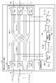
- FIG. 1 is a block diagram showing the configuration of a wavelength cross-connect device applied to a multiband transmission system according to an embodiment of the present invention
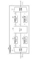
- FIG. 4 is a block diagram showing the configuration of a wavelength band switching processor of the wavelength cross-connect device of the present embodiment
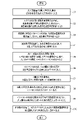
- FIG. 4 is a flowchart for explaining wavelength cross-connect operations by the wavelength cross-connect device of the present embodiment
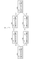
- 1 is a block diagram showing the configuration of a multi-band transmission system configured by connecting each node provided with a wavelength cross-connect device of the present embodiment in a ring with an optical transmission line
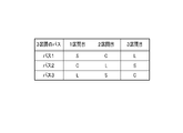
- FIG. 5 is a diagram showing a table of different wavelength bands transmitted on each path between nodes in the multi-band transmission system shown in FIG. 4;
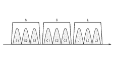
- FIG. 4 is a diagram showing wavelengths in S-band, C-band, and L-band as different wavelength bands;
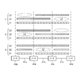
- FIG. 2 is a diagram showing optical signals of respective wavelengths in different wavelength bands, S band, C band, and L band, which are transmitted between a plurality of nodes, for explaining the wavelength continuity constraint;
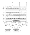
- FIG. 10 is an explanatory diagram of path setting example 1;
- FIG. 2 is a graph showing the optical signal-to-noise ratio (SNR) in the S-band, C-band and L-band;
- FIG. 2 is a diagram showing optical signals of respective wavelengths in different wavelength bands, S band, C band, and L band, which are transmitted between a plurality of nodes, for explaining capacity restrictions due to inter-band stimulated Raman scattering;
- FIG. 11 is an explanatory diagram of path setting example 2;
- FIG. 4 is a block diagram showing another configuration of the wavelength band switching processor of the wavelength cross-connect device of the present embodiment;
- FIG. 1 is a block diagram showing the configuration of a wavelength cross-connect device applied to a multiband transmission system according to an embodiment of the present invention.
- the wavelength cross-connect device 10 shown in FIG. 1 includes a WXC section 20 and a wavelength band switching section 30 .
- the WXC unit 20 is connected to each of M input paths composed of one or a plurality of optical fibers, and receives wavelength multiplexed signal lights 1a, 1b, . are input, M ⁇ 1 ⁇ N> WSS (Wavelength Selective Switch) 21a, 21b, . . . , 21m. , 22m on the output side which are fully mesh-connected (to be described later) to the M ⁇ 1 ⁇ N> WSSs 21a to 21m on the input side.
- WSS Widelength Selective Switch
- the ⁇ 1 ⁇ N> WSSs 21a to 21m on the input side are also referred to as WSSs 21a to 21m on the input side
- the ⁇ N ⁇ 1> WSSs 22a to 22m on the output side are also referred to as WSSs 22a to 22m on the output side.
- WXC unit 20 receives optical signals of different wavelength bands multiplexed into wavelength multiplexed signal light 1a, 1b, . , outputs optical signals that require wavelength band conversion to the wavelength band switching unit 30, and outputs optical signals that do not require wavelength band conversion to the output side WSSs 22a to 22m so that their routes are changed.
- the WXC unit 20 adds 1a ⁇ S, C, L> and 1b ⁇ S, C, L> shown in FIG. , 1m ⁇ S, C, L>, S-band, C-band and L-band optical signals are multiplexed.
- the output ports of the ⁇ N ⁇ 1> WSSs 22a to 22m on the output side are connected to M output routes denoted by Mo for outputting wavelength multiplexed signal light.
- the ⁇ 1 ⁇ N> WSSs 21a to 21m on the input side may be optical couplers such as 1 ⁇ N optical fiber couplers.
- the input side WSSs 21a to 21m are assumed to be the first input side WSS 21a, the second input side WSS 21b, and the Mth input side WSS 21m in order from the top of the drawing.
- the output side WSSs 22a to 22m are also assumed to be the first output side WSS 22a, the second output side WSS 22b, and the Mth output side WSS 22m in order from the top.
- This connection constitutes a route through which the above-described optical signal that does not require wavelength band conversion is transmitted for rerouting.
- Other WSSs 21b to 21m on the second to Mth input side are similarly connected.
- FIG. Other WSSs 22b to 22m on the second to Mth output side are similarly connected.
- the (NM+1) connections are configured to transmit the above-described optical signal requiring wavelength band conversion to the wavelength band switching unit 30 .
- the WSSs 21a to 21m on the input side have the same function, and have the function of N-branching each of the wavelength multiplexed signal lights 1a to 1m of multibands (wavelength bands of S band, C band and L band).
- the WSS has a function of performing N-branching by outputting each optical signal of wavelength multiplexed signal light input from an input port from an arbitrary output port, instead of simple N-branching by a coupler or the like.
- the WSS 21a splits the wavelength multiplexed signal light 1a input from one input port and outputs this split wavelength multiplexed signal light 1a from the N output ports.
- the WSSs 22a to 22m on the output side have the same function, and have a function of sequentially selecting multi-band wavelength multiplexed signal light. Taking the first output side WSS 22a as a representative, the WSS 22a sequentially selects each wavelength multiplexed signal light input from N input ports and outputs them from one output port to one output route.
- the wavelength band switching unit 30 converts optical signals of different wavelength bands multiplexed into (NM+1) wavelength multiplexed signal lights from the input side WSSs 21a to 21m into a predetermined wavelength band, and The route is changed and output to the output WSSs 22a to 22m.
- the wavelength band switching unit 30 includes ⁇ M ⁇ 1> WSSs 25a and 25b on the input side, wavelength band switching processing units 26a and 26b, and ⁇ 1 ⁇ M> WSSs 27a and 27b on the output side.
- the ⁇ M ⁇ 1> WSSs 25a and 25b on the input side have M input ports and one output port.
- the ⁇ 1 ⁇ M> WSSs 27a and 27b on the output side have 1 input port and M output ports.
- the ⁇ M ⁇ 1>WSS 25a and 25b on the input side may be an optical coupler such as an M ⁇ 1 optical fiber coupler.
- the ⁇ 1 ⁇ M> WSS 27a, 27b on the output side may be 1 ⁇ M optical couplers.
- the ⁇ M ⁇ 1> WSSs 25a and 25b constitute the first WSS described in the claims.
- the ⁇ 1 ⁇ M> WSSs 27a and 27b constitute a second WSS described in the claims.
- the input side WSS 25a, the wavelength band switching processing section 26a, and the output side WSS 27a form a set.
- FIG. This example has a first set configuration and a second set configuration.
- the output port of the ⁇ M ⁇ 1> WSS 25a is connected to the input port of the wavelength band switching processor 26a.
- the output port of the wavelength band switching processor 26a is connected to the input port of the ⁇ 1 ⁇ M> WSS 27a on the output side.
- the ⁇ 1 ⁇ M> WSS 27a changes the route to which of the M output routes the optical signal in the wavelength band converted by the wavelength band switching processing unit 26a is to be output.
- FIG. The second set configuration is also connected in the same manner as the first set configuration.
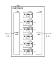
- the wavelength band switching processing units 26a and 26b include a wavelength band demultiplexing unit 31, a plurality of input-side wavelength band converting units 32 and 33, and It comprises a K ⁇ K>WSS 34 , a plurality of output-side wavelength band converters 35 and 36 , and a wavelength band multiplexer 37 .
- the ⁇ K ⁇ K> WSS 34 constitutes the specific WSS described in the claims.
- the input-side wavelength band converters 32 and 33 constitute an input-side converter described in the claims.
- the wavelength band converters 35 and 36 on the output side constitute an output-side converter described in the claims.
- the wavelength band demultiplexer 31 demultiplexes the S-band, C-band and L-band wavelength multiplexed signal light input from the ⁇ M ⁇ 1>WSS 25a (FIG. 1) on the input side, and demultiplexes the demultiplexed S-band , C-band and L-band optical signals.
- the C band is assumed to be one wavelength band (specific wavelength band) that can be processed by the ⁇ K ⁇ K> WSS 34 .
- the ⁇ K ⁇ K> WSS 34 can process only optical signals in a specific wavelength band (C band). Therefore, the demultiplexed C-band optical signal is input to the ⁇ K ⁇ K> WSS 34 as it is.
- the wavelength band conversion unit 32 on the input side of the ⁇ K ⁇ K>WSS 34 converts the S-band optical signal into a C-band optical signal and outputs it to the ⁇ K ⁇ K>WSS 34 .
- the wavelength band converter 33 converts the L-band optical signal into a C-band optical signal and outputs the optical signal to the ⁇ K ⁇ K> WSS 34 .
- the wavelength band converter 35 on the output side converts the C-band optical signal into an S-band optical signal and outputs the converted signal to the wavelength band multiplexer 37 .
- the wavelength band converter 36 converts the C-band optical signal into an L-band optical signal and outputs the L-band optical signal to the wavelength band multiplexer 37 .
- the ⁇ K ⁇ K> WSS 34 transmits the wavelength band of the optical signal multiplexed to the wavelength multiplexed signal light 1a to 1m input from the optical transmission line Mi on the input side of the wavelength cross-connect device 10 (FIG. 1) to the output side. It plays the role of switching to the wavelength band for transmission to the optical transmission line Mo (FIG. 1).
- a C-band optical signal input from the second input port of the ⁇ K ⁇ K> WSS 34 is input from the first output port to the wavelength band converter 35, where it is converted into an S-band optical signal.
- This example is conversion processing for converting an input C-band optical signal into an S-band optical signal and transmitting the converted optical signal to the optical transmission line Mo (FIG. 1) on the output side.
- the wavelength band multiplexing unit 37 multiplexes the S-band, C-band, and L-band optical signals, converts them into wavelength multiplexed signal light, and transmits the converted wavelength multiplexed signal light to ⁇ 1 ⁇ M>output to WSS 27a.
- Each of the WSSs 22a to 22m on the output side sequentially selects the S-band, C-band, and L-band wavelength-multiplexed signal lights input from the N input ports, and outputs them from the output ports to M output routes. Change the route of the wavelength multiplexed signal light.
- step S1 shown in FIG. 3 wavelength multiplexed signal lights 1a to 1m multiband-transmitted for each of M input routes shown in FIG. is entered in Optical signals of S band, C band and L band are multiplexed for each wavelength multiplexed signal light 1a to 1m.
- each of the input side WSSs 21a to 21m splits the respective wavelength multiplexed signal lights 1a to 1m. Output to the N input port. It also outputs optical signals that require wavelength band conversion to the M input ports of the ⁇ M ⁇ 1> WSSs 25 a and 25 b of the wavelength band switching unit 30 .
- step S3 the ⁇ M ⁇ 1> WSSs 25a and 25b output to the wavelength band switching processors 26a and 26b while sequentially selecting M wavelength multiplexed signal lights in which the S band, C band and L band are multiplexed. do.
- step S4 the wavelength band switching processors 26a and 26b demultiplex the input S-band, C-band, and L-band wavelength multiplexed signal light in the wavelength band demultiplexer 31 shown in FIG.
- the S-band, C-band and L-band optical signals are output.
- the C-band optical signal is input to the ⁇ K ⁇ K> WSS 34 as it is.
- the S-band optical signal is output to the wavelength band converter 32
- the L-band optical signal is output to the wavelength band converter 33 .
- step S5 the wavelength band conversion unit 32 converts the S-band optical signal into a C-band optical signal and outputs the converted signal to the ⁇ K ⁇ K> WSS 34 .
- the wavelength band converter 33 converts the L-band optical signal into a C-band optical signal and outputs the optical signal to the ⁇ K ⁇ K> WSS 34 .
- the C-band optical signal demultiplexed by the wavelength band demultiplexer 31 is output to the ⁇ K ⁇ K> WSS 34 without conversion.
- step S6 the ⁇ K ⁇ K> WSS 34 outputs C-band optical signals input from K (three) input ports from K output ports required for wavelength band conversion.
- a C-band optical signal input from the second input port of the ⁇ K ⁇ K> WSS 34 is output to the wavelength band converter 35 from the first output port.
- the wavelength band converter 35 converts the C-band optical signal into an S-band optical signal and outputs the converted signal to the wavelength band multiplexer 37 .
- the wavelength band converter 36 converts the C-band optical signal into an L-band optical signal and outputs the L-band optical signal to the wavelength band multiplexer 37 .
- Optical signals in the C band output from the ⁇ K ⁇ K> WSS 34 other than the C band are output to the wavelength band combining unit 37 without conversion.
- step S8 the wavelength band multiplexing unit 37 multiplexes the S-band, C-band, and L-band optical signals, and sends the wavelength-multiplexed signal light to the input ports of the ⁇ 1 ⁇ M> WSSs 27a and 27b shown in FIG. Output.
- each of the WSSs 22a to 22m on the output side sequentially selects S-band, C-band, and L-band wavelength multiplexed signal lights input from N input ports, and M output routes from predetermined output ports.
- the wavelength cross-connect device 10 receives light in different wavelength bands (S-band, C-band and L-band) multi-band-transmitted for each of M optical transmission lines composed of one or more optical fibers.
- the wavelength multiplexed signal lights 1a to 1m in which the signals are multiplexed are branched into N, which is a number larger than M, at the input side WSSs 21a to 21m. Further, the output side WSSs 22a to 22m mesh-connected to the input side WSSs 21a to 21m change the route of the N-branched wavelength multiplexed signal light and output it to the output side route.
- the wavelength cross-connect device 10 includes a WXC section 20 and a wavelength band switching section 30 .
- the WXC unit 20 receives input side WSSs 21a to 21m and wavelength multiplexed signal light obtained by multiplexing optical signals that do not require wavelength band conversion among the wavelength multiplexed signal lights branched by the input side WSSs 21a to 21m.
- Output side WSSs 22a to 22m are provided.
- the wavelength band switching unit 30 converts the wavelength band of the wavelength multiplexed signal light, which is obtained by multiplexing the optical signals requiring wavelength band conversion from the wavelength multiplexed signal light N-branched for each of the input side WSSs 21a to 21m, into a different wavelength band. At the same time, the route is changed to output to the output side WSSs 22a to 22m.
- the wavelength cross-connect device 10 transmits the wavelength multiplexed signal lights 1a to 1m in which the optical signals of different wavelength bands that have been multiband-transmitted are multiplexed at the input side WSSs 21a to 21m of the WXC section 20.
- the wavelength band of the wavelength multiplexed signal light obtained by multiplexing the optical signals requiring wavelength band conversion from the N-branched wavelength multiplexed signal light is converted to a different wavelength band by the wavelength band switching unit 30 and the route is changed. can be output to the route Mo on the output side via the WSSs 22a to 22m on the output side.
- wavelength band conversion can be performed in units of links and in units of wavelengths, which will be described later.
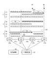
- the wavelength in the vacant wavelength band of the optical transmission line between the nodes 40a and 40b (for example, the wavelength C1 of the C band) is converted by the wavelength cross-connect device 10 on the front side of the section between the nodes 40a and 40b.
- the wavelengths in the wavelength band in the wavelength vacant section can be set to be usable in this manner, the usable capacity of the network can be improved. That is, it is possible to improve the utilization efficiency of the network of the multiband transmission system.
- a multiband transmission system (also referred to as system) 40 shown in FIG. 41b, 41c, 41d, 41e, and 41f are connected in a ring shape.
- the above-mentioned link unit is the unit of the optical transmission line 41a that connects two adjacent node (for example, nodes 40a and 40b) sections in the system 40. In other words, it is the unit of two adjacent node intervals.
- optical signals of different wavelength bands are transmitted through optical transmission lines 41a, 41b, and 41c between nodes 40a, 40b, 40c, and 40d starting at node 40a and ending at node 40d.
- Multiband transmission has been limited to transmission in one wavelength band in one path.
- the nodes 40a-40b-40c-40d are also referred to as nodes 40a . . . 40d.
- the path 1 passing through the optical transmission lines 41a to 41c transmits only the optical signal in the S band
- Path 2 was limited to transmitting only C-band optical signals
- path 3 was limited to transmitting only L-band optical signals.
- multiband transmission is characterized by a power transition from an optical signal with a short wavelength to an optical signal with a long wavelength. Therefore, in the above example, the transmission performance of the optical signal in the S band of path 1 is poor, the transmission performance of the optical signal in the C band of path 2 is normal, and the transmission performance of the optical signal in the L band of path 3 is low. In many cases, the transmission performance of optical signals is improved. In this way, there was a deviation in transmission performance among the paths 1, 2, and 3.
- Transmission performance is determined by parameters such as the transmission band and amount of loss as the performance of devices (optical products) such as optical fibers, and stimulated Raman scattering (SRS), which is one of the nonlinear optical effects. .
- the above parameters are strongly band dependent. Since the transmission performance depends on the wavelength band used as described above, deviations occur between different wavelength bands.
- the wavelength cross-connect device 10 can change the wavelength band for each section (link unit) between the nodes 40a...40d.
- an S-band optical signal is transmitted in the first section (between nodes 40a-40b), and an S-band optical signal is transmitted in the second section (between nodes 40b).
- C-band optical signals are transmitted.
- An L-band optical signal is transmitted in the third section (between nodes 40c and 40d).
- the C-band optical signal is transmitted in the first section
- the L-band optical signal is transmitted in the second section
- the S-band optical signal is transmitted in the third section.
- an L-band optical signal is transmitted in the first section
- an S-band optical signal is transmitted in the second section
- a C-band optical signal is transmitted in the third section.
- the S band of the optical signal consists of wavelengths S1, S2 and S3
- the C band consists of wavelengths C1, C2 and C3
- the L band consists of wavelengths L1, L2 and L3.
- the wavelength cross-connect device 10 can set any wavelength in different wavelength bands for each of the paths 1, 2, and 3 in each section of the nodes 40a-40b-40c-40d.
- an S-band wavelength S1 is set for the path 1 of the optical transmission line 41a between the nodes 40a and 40b
- a C-band wavelength C1 is set for the path 2 of the optical transmission line 41b between the nodes 40b and 40c
- An L-band wavelength L1 is set for the path 3 of the optical transmission line 41c in the -40d section, and optical signals can be transmitted at the set wavelengths S1, C1, and L1.
- wavelength continuity constraint refers to the need to continuously transmit the same wavelength within one wavelength band on one path between the nodes 40a...40d.
- the wavelength cross-connect device 10 can convert the wavelength band on a wavelength-by-wavelength basis, so for example, the wavelength C2 shown in the elliptical dashed frame of the C band between the nodes 40a and 40b can be set. Furthermore, a wavelength S2 shown in an elliptical dashed frame in the S band between the nodes 40b-40c can be set, and a wavelength L2 shown in the L band elliptical dashed frame between the nodes 40c to 40d can be set.
- the wavelength C2 of the waveband C is used between the nodes 40a and 40b
- the wavelength S2 of the waveband S is used between the nodes 40b and 40c
- the wavelength L2 of the waveband L is used between the nodes 40c and 40d. can transmit optical signals.
- the free wavelengths indicated by the dashed elliptical frames can be used to transmit optical signals in such a way that wavelength collision can be avoided, so the capacity of the network can be improved. That is, it is possible to improve the utilization efficiency of the network of the multiband transmission system.
- such a conversion of the wavelength band on a wavelength-by-wavelength basis can alleviate the capacity constraint due to inter-band stimulated Raman scattering that occurs in the S band.
- path setting example 1 will be described with reference to FIG.
- a path setting device 55 is connected to each of the nodes 40a to 40d.
- the path setting device 55 is connected to an external terminal 56 such as a personal computer for placing an order for path setting.
- a plurality of arrows W1 indicate wavelength band switching points.
- the path setting device 55 manages the usage of wavelengths between the nodes 40a...40d. For example, when an order for setting a new path between the nodes 40a .
- the device 55 checks the availability of wavelengths.
- the path setting device 55 gives the following instructions (1) to (4) in response to confirmation of the wavelength availability.
- the path setting device 55 instructs the node 40a to transmit the C-band wavelength C2 to the node 40b as indicated by the arrow Y11 in order to set an optical path on the optical transmission line 41a.
- the path setting device 55 switches the C-band of the input optical signal of wavelength C2 to the S-band to the node 40b as indicated by the arrow Y12. , to convert it into an optical signal of wavelength S2 and transmit it to node 40c.
- the path setting device 55 switches the S-band of the input optical signal of the wavelength S2 to the L-band to the node 40c as indicated by the arrow Y13. , to convert it into an optical signal of wavelength L2 and transmit it to the node 40d.
- the path setting device 55 may instruct the node 40d to return to the S-band wavelength S2. This is done when the usable wavelength band is determined at the start and end points of the path.
- the SNR of the S-band, C-band, and L-band increases as the frequency of the wavelength band increases, in other words, as the wavelength of the wavelength band increases, as indicated by the solid line 52. It decreases as it becomes shorter.
- the SNR is the worst in the S band. For this reason, as indicated by the dashed horizontal bar 54 in FIG. 10, optical signals cannot be transmitted through the S band between the nodes 40a-40b-40c-40d.
- the wavelength cross-connect device 10 can convert the wavelength band in units of wavelengths, so the wavelengths of different wavelength bands can be set in the wavelength vacant sections indicated by the dashed elliptical frames as follows. That is, the wavelength C3 is set between the nodes 40a and 40b, the wavelength S3 is set between the nodes 40b and 40c, and the wavelength L3 is set between the nodes 40c and 40d. With this setting, the wavelength C3 of the waveband C is used between the nodes 40a and 40b, the wavelength S3 of the waveband S is used between the nodes 40b and 40c, and the wavelength L3 of the waveband L is used between the nodes 40c and 40d. As a result, optical signals can be transmitted while mitigating the effects of inter-band stimulated Raman scattering.
- path setting example 2 will be described with reference to FIG. However, as shown in FIG. 8, each of the nodes 40a to 40d is connected with a path setting device 55 to which an external terminal 56 is connected.
- the path setting device 55 manages the usage of wavelengths between the nodes 40a...40d. For example, when an order for setting a new path between the nodes 40a to 40d is added by the external terminal 56, the path setting device 55 confirms the availability of wavelengths. In the example of FIG. 11, it is possible to set a path between the nodes 40a to 40d at wavelength S3. However, if, for example, it is specified that up to two consecutive links can be set for the wavelength S3 as a setting condition, paths cannot be set for the optical transmission lines 41a, 41b, and 41c for the wavelength S3.
- the path setting device 55 issues the following instructions (1) to (4) in response to confirmation of the wavelength availability.
- the path setting device 55 instructs the node 40a to transmit an optical signal having a wavelength S3 in the S band to the node 40b, as indicated by an arrow Y21, in order to set an optical path in the optical transmission line 41a. instruct.
- Path setting device 55 sends the input optical signal of wavelength S3 to node 40c as it is, as indicated by arrow Y21, in order to set an optical path on optical transmission line 41b for node 40b. Instruct to send.
- the path setting device 55 switches the S-band of the input optical signal of wavelength S3 to the L-band in order to set an optical path on the optical transmission line 41c to the node 40c, as indicated by an arrow Y22. , is converted into an optical signal of wavelength L3 and transmitted to the node 40d.
- the path setting device 55 may instruct the node 40d to return to the S-band wavelength S2. This is done when the usable wavelength band is determined at the start and end points of the path.
- optical signals can be transmitted between the nodes 40a . Therefore, it is possible to improve the usage capacity of the network in the multi-band transmission system and improve the utilization efficiency of the network.
- the network efficiency decreases from 100% due to wavelength continuity restrictions, and further due to capacity restrictions due to the effects of inter-band stimulated Raman scattering.
- the decrease in network efficiency can be suppressed.
- the wavelength band switching unit 30 includes a ⁇ M ⁇ 1> WSS 25a as a first WSS that sequentially selects and outputs a plurality of wavelength multiplexed signal lights from the input side WSSs 21a to 21m. It also has a wavelength band switching processor 26a that converts the wavelength band multiplexed in the wavelength multiplexed signal light from the ⁇ M ⁇ 1> WSS 25a into a different wavelength band and outputs the wavelength multiplexed signal light. Further, a ⁇ 1 ⁇ M> WSS 27a is provided as a second WSS input to each of the output side WSSs 22a to 22m so that the wavelength multiplexed signal light from the wavelength band switching processing unit 26a is branched and routed.
- the ⁇ M ⁇ 1>WSS 25a, the wavelength band switching processing unit 26a, and the ⁇ 1 ⁇ M>WSS 27a described above are provided as one set of configuration.
- One set of configuration includes the same number of wavelength multiplexed signal lights in which optical signals requiring wavelength band conversion among the N-branched wavelength multiplexed signal lights for each of the input side WSSs 21a to 21m are multiplexed. .
- the number of wavelength bands to be switched can be increased in units of one set. so it can be easily increased.
- Waveband switching processors 26a and 26b include wavelength band demultiplexer 31, wavelength band converters 32 and 33 as input side converters, ⁇ K ⁇ K> WSS 34 as specific WSS, and output side
- the wavelength band converters 35 and 36 as converters and the wavelength band multiplexer 37 are provided.
- the wavelength band demultiplexing unit 31 demultiplexes and outputs optical signals of different wavelength bands multiplexed with wavelength multiplexed signal light from ⁇ M ⁇ 1> WSSs 25a and 25b as first WSSs on the input side.
- the wavelength band conversion units 32 and 33 as input side conversion units convert optical signals in wavelength bands other than a predetermined specific wavelength band among the optical signals in different wavelength bands demultiplexed by the wavelength band demultiplexing unit 31. , into an optical signal of the specific wavelength band.
- the ⁇ K ⁇ K> WSS 34 has the same number of input ports and output ports as the number of demultiplexed waves in the wavelength band demultiplexing unit 31, and can process only a specific wavelength band.
- the specific wavelength band converted by the converters 32 and 33 or the specific wavelength band within the different wavelength bands demultiplexed is output from the output port so as to be converted into a predetermined wavelength band.
- Wavelength band converters 35 and 36 as output side converters convert optical signals in a specific wavelength band output from output ports into optical signals in a predetermined wavelength band.
- the wavelength band multiplexer 37 multiplexes the optical signals of different wavelength bands from the wavelength band converters 35 and 36, converts them into wavelength multiplexed signal light, and supplies them to ⁇ 1 ⁇ M> WSSs 27a and 27b as second WSSs. Output.
- the ⁇ K ⁇ K> WSS 34 allows a specific wavelength band converted by the wavelength band converters 32 and 33 on the input side, or a specific wavelength band within a different wavelength band demultiplexed by the wavelength band demultiplexer 31 A waveband is output from the output port to convert to a predetermined waveband.
- one ⁇ K ⁇ K> WSS 34 can convert optical signals of different wavelength bands into optical signals of a predetermined wavelength band, so that the wavelength band switching processors 26a and 26b can be miniaturized.
- wavelength band switching processing units 26a and 26b may be configured such that the wavelength band switching processing unit 26a is representatively shown in FIG.
- the wavelength band switching processing unit 26a shown in FIG. It is configured.
- P is the same number as ⁇ 1 ⁇ P> the number of output ports of WSS 61, the number of input ports of ⁇ P ⁇ 1> WSS 63, and the number of wavelength band converters 62a to 62f.
- either one of ⁇ 1 ⁇ P>WSS 61 and ⁇ P ⁇ 1>WSS 63 may be an optical coupler such as a 1 ⁇ P or P ⁇ 1 optical fiber coupler.
- the ⁇ 1 ⁇ P>WSS 61 constitutes the third WSS described in the claims.
- the ⁇ P ⁇ 1>WSS 63 constitutes the fourth WSS described in the claims.
- the ⁇ 1 ⁇ P> WSS 61 P-splits each optical signal of the S band, C band and L band of different wavelength bands multiplexed with the wavelength multiplexed signal light input from the ⁇ M ⁇ 1> WSS 25a (FIG. 1). do.
- This P-branching is performed by including a predetermined number of optical signals of the same wavelength band.
- two S-band, C-band and L-band optical signals are included and P-branched as follows. That is, the S-band optical signals are output to the wavelength band conversion units 62a and 62b, the C-band optical signals are output to the wavelength band conversion units 62c and 62d, and the L-band optical signals are output to the wavelength band conversion units 62e and 62d. output.
- the wavelength band converter 62 a converts the S band into a C band optical signal
- the wavelength band converter 62 b converts the S band into an L band optical signal and outputs the signal to the input port of the ⁇ P ⁇ 1> WSS 63
- the wavelength band converter 62 c converts the C band into an S band optical signal
- the wavelength band converter 62 d converts the C band into an L band optical signal and outputs it to the input port of the ⁇ P ⁇ 1> WSS 63
- the wavelength band converter 62e converts the L-band into an S-band optical signal
- the wavelength band converter 62f converts the L-band into a C-band optical signal for output to the input port of the ⁇ P ⁇ 1> WSS 63 .
- the ⁇ P ⁇ 1> WSS 63 multiplexes two S-band, C-band and L-band input to the P input ports, and sends the wavelength-multiplexed signal light to the ⁇ 1 ⁇ M> WSS 27a shown in FIG. Output.
- the wavelength band switching processing units 26a and 26b having a simple configuration can convert different wavelength bands multiplexed into the wavelength multiplexed signal light from the WXC unit 20 into optical signals of other different wavelength bands. .
- a WSS that can handle at least two or more wavelength bands may be used in the wavelength band switching processing unit 26a shown in FIG. 2 or FIG.
- the WSS 34 capable of processing the S-band, C-band and L-band shown in FIG.
- the WSS of the E-band and S-band and the WSS of the C-band and L-band may be provided.
- the configuration may be such that each of the four wavelength bands can be processed in half.
- a wavelength cross-connect device wherein the wavelength cross-connect device is configured for each of M optical transmission lines each composed of one or a plurality of optical fibers and having different wavelength bands transmitted in multiband.
- Wavelength multiplexed signal light obtained by multiplexing optical signals is branched by M input-side WSSs (Wavelength Selective Switches) into N, the number of which is larger than M, and the N-branched wavelength-multiplexed signal light is transferred to the input side.
- Relay processing is performed to change the route and output through M output side WSSs mesh-connected to the WSS.
- a WXC (Wavelength Cross Connect) unit having the output side WSS to which wavelength multiplexed signal light obtained by multiplexing optical signals that do not require wavelength band conversion is input, and N wavelengths branched for each of the input side WSSs a wavelength band switching unit that converts the wavelength band of the wavelength multiplexed signal light obtained by multiplexing the optical signal requiring wavelength band conversion from the multiplexed signal light into a different wavelength band, changes the route, and outputs the wavelength band to the output side WSS;
- a wavelength cross-connect device characterized by comprising:
- the wavelength cross-connect device splits, at the input side WSS of the WXC unit, N wavelength multiplexed signal lights in which optical signals of different wavelength bands transmitted in multiple bands are multiplexed.
- the wavelength band of the wavelength multiplexed signal light obtained by multiplexing the optical signals requiring wavelength band conversion from the N-branched wavelength multiplexed signal light is converted to a different wavelength band and the route is changed by the wavelength band switching unit. It can be output to the output-side route via the output-side WSS.
- wavelength band conversion can be performed on a link-by-link basis and a wavelength-by-wavelength basis.
- the wavelength in the vacant wavelength band of the optical transmission line in the node section (for example, the wavelength C1 in the C band) can be converted and used by the wavelength cross-connect device on the front side of the node section. Since the wavelengths in the wavelength band in the wavelength vacant section can be set to be usable in this manner, the usable capacity of the network can be improved. That is, it is possible to improve the utilization efficiency of the network of the multiband transmission system.
- the wavelength band switching unit sequentially selects and outputs a plurality of wavelength multiplexed signal lights from the input side WSS one by one, and multiplexes the wavelength multiplexed signal lights from the first WSS.
- a wavelength band switching processing unit for outputting wavelength multiplexed signal light converted from a wavelength band to a different wavelength band;
- a second WSS input to each WSS is provided as one set of configuration, and the one set of configuration multiplexes optical signals requiring wavelength band conversion among the N-branched wavelength multiplexed signal light for each of the input side WSSs.
- the number of wavelength bands can be increased by increasing the number of constituent units per set. , can be easily increased.
- the wavelength band switching processing unit includes a wavelength band demultiplexing unit for demultiplexing and outputting optical signals of different wavelength bands multiplexed with the wavelength multiplexed signal light from the first WSS, and an input-side converter for converting optical signals in wavelength bands other than a predetermined specific wavelength band among optical signals in different wavelength bands into optical signals in the specific wavelength band; having a port and an output port, capable of processing only the specific wavelength band, and the specific wavelength band input from the input port converted by the input side conversion unit, or the demultiplexed wavelength band within the different wavelength band
- a specific WSS that outputs from the output port so as to convert a specific wavelength band into a predetermined wavelength band, and an output that converts the optical signal of the specific wavelength band output from the output port into an optical signal of the predetermined wavelength band and a wavelength band multiplexing unit for multiplexing the optical signals of different wavelength bands from the output side conversion unit, converting them into wavelength multiplexed signal light, and outputting them to the second WSS.
- the wavelength cross-connect device
- the specific wavelength band converted by the input-side conversion unit or the specific wavelength band within a different wavelength band demultiplexed by the wavelength band demultiplexing unit is converted into a predetermined wavelength band by the specific WSS. is output from the output port as follows.
- one specific WSS can convert each optical signal of a different wavelength band into an optical signal of a predetermined wavelength band, so that the wavelength band switching processor can be miniaturized.
- the wavelength band switching processing unit includes a third WSS for branching different wavelength bands multiplexed into the wavelength multiplexed signal light from the first WSS, including a predetermined number of optical signals of the same wavelength band, and the third WSS. a wavelength band conversion unit that converts optical signals of wavelength bands branched by the splitter into optical signals of different wavelength bands, and multiplexes the optical signals of each wavelength band converted by the wavelength band conversion units.
- a wavelength band switching processing unit having a simple configuration can convert a different wavelength band multiplexed into the wavelength multiplexed signal light from the WXC unit into an optical signal of another different wavelength band.
- wavelength cross-connect device 20 WXC unit 21a to 21m ⁇ 1 ⁇ N> WSS (input side WSS) 22a to 22m ⁇ N x 1> WSS (output side WSS) 30 wavelength band switching unit 25a, 25b ⁇ M ⁇ 1>WSS (first WSS) 26a, 26b Waveband switching processor 27a, 27b ⁇ 1 ⁇ M> WSS (second WSS) 31 wavelength band demultiplexer 32, 33 wavelength band converter (input side converter) 34 ⁇ K ⁇ K> WSS (specific WSS) 35, 36 wavelength band converter (output side converter) 37 wavelength band combining unit 61 ⁇ 1 ⁇ P> WSS (third WSS) 62a to 62f wavelength band conversion unit 63 ⁇ P ⁇ 1> WSS (fourth WSS)
Landscapes
- Engineering & Computer Science (AREA)
- Computer Networks & Wireless Communication (AREA)
- Signal Processing (AREA)
- Computing Systems (AREA)
- Physics & Mathematics (AREA)
- Electromagnetism (AREA)
- Optical Communication System (AREA)
Priority Applications (3)
| Application Number | Priority Date | Filing Date | Title |
|---|---|---|---|
| US18/567,502 US12684272B2 (en) | 2021-06-07 | 2021-06-07 | Wavelength cross connect device, and wavelength cross connect method |
| JP2023527162A JP7687395B2 (ja) | 2021-06-07 | 2021-06-07 | 波長クロスコネクト装置及び波長クロスコネクト方法 |
| PCT/JP2021/021584 WO2022259318A1 (ja) | 2021-06-07 | 2021-06-07 | 波長クロスコネクト装置及び波長クロスコネクト方法 |
Applications Claiming Priority (1)
| Application Number | Priority Date | Filing Date | Title |
|---|---|---|---|
| PCT/JP2021/021584 WO2022259318A1 (ja) | 2021-06-07 | 2021-06-07 | 波長クロスコネクト装置及び波長クロスコネクト方法 |
Publications (1)
| Publication Number | Publication Date |
|---|---|
| WO2022259318A1 true WO2022259318A1 (ja) | 2022-12-15 |
Family
ID=84424932
Family Applications (1)
| Application Number | Title | Priority Date | Filing Date |
|---|---|---|---|
| PCT/JP2021/021584 Ceased WO2022259318A1 (ja) | 2021-06-07 | 2021-06-07 | 波長クロスコネクト装置及び波長クロスコネクト方法 |
Country Status (3)
| Country | Link |
|---|---|
| US (1) | US12684272B2 (cg-RX-API-DMAC7.html) |
| JP (1) | JP7687395B2 (cg-RX-API-DMAC7.html) |
| WO (1) | WO2022259318A1 (cg-RX-API-DMAC7.html) |
Families Citing this family (1)
| Publication number | Priority date | Publication date | Assignee | Title |
|---|---|---|---|---|
| US12563323B2 (en) * | 2021-06-07 | 2026-02-24 | Ntt, Inc. | Wavelength cross connect device, and wavelength cross connect method |
Citations (5)
| Publication number | Priority date | Publication date | Assignee | Title |
|---|---|---|---|---|
| JP2003219440A (ja) * | 2002-01-18 | 2003-07-31 | Nec Corp | 光クロスコネクトシステムおよび光デアグリゲータ |
| US20040153492A1 (en) * | 2002-09-20 | 2004-08-05 | Xiaojun Cao | Efficient optical network design using multi-granular optical cross-connects with wavelength band switching |
| JP2006191212A (ja) * | 2004-12-28 | 2006-07-20 | Fujitsu Ltd | 光ノードおよび光分岐挿入装置 |
| EP2773057A1 (en) * | 2013-02-27 | 2014-09-03 | Alcatel Lucent | Optical network node and method of transmitting wavelength multiplexed optical data signals |
| JP2018191109A (ja) * | 2017-05-01 | 2018-11-29 | 日本電信電話株式会社 | 光通信ノード |
Family Cites Families (1)
| Publication number | Priority date | Publication date | Assignee | Title |
|---|---|---|---|---|
| US20150256908A1 (en) * | 2014-03-05 | 2015-09-10 | Oplink Communications, Inc. | N-degree cdc wsx roadm |
-
2021
- 2021-06-07 US US18/567,502 patent/US12684272B2/en active Active
- 2021-06-07 JP JP2023527162A patent/JP7687395B2/ja active Active
- 2021-06-07 WO PCT/JP2021/021584 patent/WO2022259318A1/ja not_active Ceased
Patent Citations (5)
| Publication number | Priority date | Publication date | Assignee | Title |
|---|---|---|---|---|
| JP2003219440A (ja) * | 2002-01-18 | 2003-07-31 | Nec Corp | 光クロスコネクトシステムおよび光デアグリゲータ |
| US20040153492A1 (en) * | 2002-09-20 | 2004-08-05 | Xiaojun Cao | Efficient optical network design using multi-granular optical cross-connects with wavelength band switching |
| JP2006191212A (ja) * | 2004-12-28 | 2006-07-20 | Fujitsu Ltd | 光ノードおよび光分岐挿入装置 |
| EP2773057A1 (en) * | 2013-02-27 | 2014-09-03 | Alcatel Lucent | Optical network node and method of transmitting wavelength multiplexed optical data signals |
| JP2018191109A (ja) * | 2017-05-01 | 2018-11-29 | 日本電信電話株式会社 | 光通信ノード |
Also Published As
| Publication number | Publication date |
|---|---|
| JPWO2022259318A1 (cg-RX-API-DMAC7.html) | 2022-12-15 |
| JP7687395B2 (ja) | 2025-06-03 |
| US12684272B2 (en) | 2026-07-14 |
| US20240373152A1 (en) | 2024-11-07 |
Similar Documents
| Publication | Publication Date | Title |
|---|---|---|
| JP4875237B2 (ja) | 波長変換装置を用いた波長分割多重伝送方法 | |
| US7164861B2 (en) | Node apparatus, optical wavelength division multiplexing network, and system switching method | |
| JP7609272B2 (ja) | 波長クロスコネクト装置及び波長クロスコネクト方法 | |
| JP7472982B2 (ja) | 波長クロスコネクト装置、マルチバンド伝送システム及びマルチバンド伝送方法 | |
| JP4152932B2 (ja) | 光分波方法および光合波方法、並びに、それを用いた光伝送装置 | |
| JP7694655B2 (ja) | 波長クロスコネクト装置及び波長クロスコネクト方法 | |
| JP2019075654A (ja) | 伝送システム及び伝送方法 | |
| US7577361B2 (en) | Optical network system and optical coupling apparatus | |
| JP7687395B2 (ja) | 波長クロスコネクト装置及び波長クロスコネクト方法 | |
| JP4852491B2 (ja) | 光クロスコネクトスイッチ機能部及び光クロスコネクト装置 | |
| US20040208540A1 (en) | Node and wavelength division multiplexing ring network | |
| JP7786567B2 (ja) | 波長クロスコネクト装置、および、波長クロスコネクト方法 | |
| JP5473529B2 (ja) | ノード装置および光伝送システム | |
| EP1427122B1 (en) | Bidirectional wavelength division multiplexing self-healing ring network | |
| JP2024126813A (ja) | 波長変換装置、光伝送装置及び波長変換方法 | |
| JP4744311B2 (ja) | 光伝送ネットワーク | |
| JP7294461B2 (ja) | 波長クロスコネクト装置及び波長クロスコネクト方法 | |
| WO2024052963A1 (ja) | 光ノードおよび光交換機 | |
| WO2022259321A1 (ja) | 波長クロスコネクト装置及び波長クロスコネクト方法 | |
| JP5081726B2 (ja) | 光伝送システム | |
| JP5068233B2 (ja) | 光中継装置 | |
| JP5340369B2 (ja) | 光中継装置 | |
| JP2012050143A (ja) | 光中継装置 | |
| JP2005303730A (ja) | 光分岐挿入装置及び光分岐挿入装置体 | |
| JPH08149088A (ja) | 光多重通信網およびノード装置 |
Legal Events
| Date | Code | Title | Description |
|---|---|---|---|
| 121 | Ep: the epo has been informed by wipo that ep was designated in this application |
Ref document number: 21944999 Country of ref document: EP Kind code of ref document: A1 |
|
| WWE | Wipo information: entry into national phase |
Ref document number: 2023527162 Country of ref document: JP |
|
| NENP | Non-entry into the national phase |
Ref country code: DE |
|
| 122 | Ep: pct application non-entry in european phase |
Ref document number: 21944999 Country of ref document: EP Kind code of ref document: A1 |
|
| WWG | Wipo information: grant in national office |
Ref document number: 18567502 Country of ref document: US |