WO2022254815A1 - 分離システム及び分離方法 - Google Patents
分離システム及び分離方法 Download PDFInfo
- Publication number
- WO2022254815A1 WO2022254815A1 PCT/JP2022/006714 JP2022006714W WO2022254815A1 WO 2022254815 A1 WO2022254815 A1 WO 2022254815A1 JP 2022006714 W JP2022006714 W JP 2022006714W WO 2022254815 A1 WO2022254815 A1 WO 2022254815A1
- Authority
- WO
- WIPO (PCT)
- Prior art keywords
- pet
- section
- solution
- impurities
- reaction
- Prior art date
- Legal status (The legal status is an assumption and is not a legal conclusion. Google has not performed a legal analysis and makes no representation as to the accuracy of the status listed.)
- Ceased
Links
Images


Classifications
-
- C—CHEMISTRY; METALLURGY
- C08—ORGANIC MACROMOLECULAR COMPOUNDS; THEIR PREPARATION OR CHEMICAL WORKING-UP; COMPOSITIONS BASED THEREON
- C08J—WORKING-UP; GENERAL PROCESSES OF COMPOUNDING; AFTER-TREATMENT NOT COVERED BY SUBCLASSES C08B, C08C, C08F, C08G or C08H
- C08J11/00—Recovery or working-up of waste materials
- C08J11/04—Recovery or working-up of waste materials of polymers
- C08J11/10—Recovery or working-up of waste materials of polymers by chemically breaking down the molecular chains of polymers or breaking of crosslinks, e.g. devulcanisation
- C08J11/18—Recovery or working-up of waste materials of polymers by chemically breaking down the molecular chains of polymers or breaking of crosslinks, e.g. devulcanisation by treatment with organic material
- C08J11/22—Recovery or working-up of waste materials of polymers by chemically breaking down the molecular chains of polymers or breaking of crosslinks, e.g. devulcanisation by treatment with organic material by treatment with organic oxygen-containing compounds
- C08J11/24—Recovery or working-up of waste materials of polymers by chemically breaking down the molecular chains of polymers or breaking of crosslinks, e.g. devulcanisation by treatment with organic material by treatment with organic oxygen-containing compounds containing hydroxyl groups
-
- B—PERFORMING OPERATIONS; TRANSPORTING
- B01—PHYSICAL OR CHEMICAL PROCESSES OR APPARATUS IN GENERAL
- B01D—SEPARATION
- B01D3/00—Distillation or related exchange processes in which liquids are contacted with gaseous media, e.g. stripping
- B01D3/14—Fractional distillation or use of a fractionation or rectification column
- B01D3/143—Fractional distillation or use of a fractionation or rectification column by two or more of a fractionation, separation or rectification step
-
- B—PERFORMING OPERATIONS; TRANSPORTING
- B01—PHYSICAL OR CHEMICAL PROCESSES OR APPARATUS IN GENERAL
- B01J—CHEMICAL OR PHYSICAL PROCESSES, e.g. CATALYSIS OR COLLOID CHEMISTRY; THEIR RELEVANT APPARATUS
- B01J19/00—Chemical, physical or physico-chemical processes in general; Their relevant apparatus
- B01J19/0006—Controlling or regulating processes
-
- B—PERFORMING OPERATIONS; TRANSPORTING
- B01—PHYSICAL OR CHEMICAL PROCESSES OR APPARATUS IN GENERAL
- B01J—CHEMICAL OR PHYSICAL PROCESSES, e.g. CATALYSIS OR COLLOID CHEMISTRY; THEIR RELEVANT APPARATUS
- B01J19/00—Chemical, physical or physico-chemical processes in general; Their relevant apparatus
- B01J19/24—Stationary reactors without moving elements inside
-
- B—PERFORMING OPERATIONS; TRANSPORTING
- B29—WORKING OF PLASTICS; WORKING OF SUBSTANCES IN A PLASTIC STATE IN GENERAL
- B29B—PREPARATION OR PRETREATMENT OF THE MATERIAL TO BE SHAPED; MAKING GRANULES OR PREFORMS; RECOVERY OF PLASTICS OR OTHER CONSTITUENTS OF WASTE MATERIAL CONTAINING PLASTICS
- B29B17/00—Recovery of plastics or other constituents of waste material containing plastics
- B29B17/02—Separating plastics from other materials
-
- C—CHEMISTRY; METALLURGY
- C08—ORGANIC MACROMOLECULAR COMPOUNDS; THEIR PREPARATION OR CHEMICAL WORKING-UP; COMPOSITIONS BASED THEREON
- C08J—WORKING-UP; GENERAL PROCESSES OF COMPOUNDING; AFTER-TREATMENT NOT COVERED BY SUBCLASSES C08B, C08C, C08F, C08G or C08H
- C08J11/00—Recovery or working-up of waste materials
- C08J11/04—Recovery or working-up of waste materials of polymers
- C08J11/06—Recovery or working-up of waste materials of polymers without chemical reactions
- C08J11/08—Recovery or working-up of waste materials of polymers without chemical reactions using selective solvents for polymer components
-
- B—PERFORMING OPERATIONS; TRANSPORTING
- B01—PHYSICAL OR CHEMICAL PROCESSES OR APPARATUS IN GENERAL
- B01J—CHEMICAL OR PHYSICAL PROCESSES, e.g. CATALYSIS OR COLLOID CHEMISTRY; THEIR RELEVANT APPARATUS
- B01J19/00—Chemical, physical or physico-chemical processes in general; Their relevant apparatus
- B01J19/0006—Controlling or regulating processes
- B01J19/0013—Controlling the temperature of the process
-
- B—PERFORMING OPERATIONS; TRANSPORTING
- B01—PHYSICAL OR CHEMICAL PROCESSES OR APPARATUS IN GENERAL
- B01J—CHEMICAL OR PHYSICAL PROCESSES, e.g. CATALYSIS OR COLLOID CHEMISTRY; THEIR RELEVANT APPARATUS
- B01J19/00—Chemical, physical or physico-chemical processes in general; Their relevant apparatus
- B01J19/30—Loose or shaped packing elements, e.g. Raschig rings or Berl saddles, for pouring into the apparatus for mass or heat transfer
-
- B—PERFORMING OPERATIONS; TRANSPORTING
- B01—PHYSICAL OR CHEMICAL PROCESSES OR APPARATUS IN GENERAL
- B01J—CHEMICAL OR PHYSICAL PROCESSES, e.g. CATALYSIS OR COLLOID CHEMISTRY; THEIR RELEVANT APPARATUS
- B01J2219/00—Chemical, physical or physico-chemical processes in general; Their relevant apparatus
- B01J2219/30—Details relating to random packing elements
- B01J2219/302—Basic shape of the elements
- B01J2219/30203—Saddle
-
- B—PERFORMING OPERATIONS; TRANSPORTING
- B01—PHYSICAL OR CHEMICAL PROCESSES OR APPARATUS IN GENERAL
- B01J—CHEMICAL OR PHYSICAL PROCESSES, e.g. CATALYSIS OR COLLOID CHEMISTRY; THEIR RELEVANT APPARATUS
- B01J2219/00—Chemical, physical or physico-chemical processes in general; Their relevant apparatus
- B01J2219/30—Details relating to random packing elements
- B01J2219/302—Basic shape of the elements
- B01J2219/30215—Toroid or ring
-
- B—PERFORMING OPERATIONS; TRANSPORTING
- B01—PHYSICAL OR CHEMICAL PROCESSES OR APPARATUS IN GENERAL
- B01J—CHEMICAL OR PHYSICAL PROCESSES, e.g. CATALYSIS OR COLLOID CHEMISTRY; THEIR RELEVANT APPARATUS
- B01J2219/00—Chemical, physical or physico-chemical processes in general; Their relevant apparatus
- B01J2219/30—Details relating to random packing elements
- B01J2219/302—Basic shape of the elements
- B01J2219/30296—Other shapes
-
- B—PERFORMING OPERATIONS; TRANSPORTING
- B29—WORKING OF PLASTICS; WORKING OF SUBSTANCES IN A PLASTIC STATE IN GENERAL
- B29B—PREPARATION OR PRETREATMENT OF THE MATERIAL TO BE SHAPED; MAKING GRANULES OR PREFORMS; RECOVERY OF PLASTICS OR OTHER CONSTITUENTS OF WASTE MATERIAL CONTAINING PLASTICS
- B29B17/00—Recovery of plastics or other constituents of waste material containing plastics
- B29B17/02—Separating plastics from other materials
- B29B2017/0213—Specific separating techniques
- B29B2017/0217—Mechanical separating techniques; devices therefor
- B29B2017/0234—Mechanical separating techniques; devices therefor using gravity, e.g. separating by weight differences in a wind sifter
-
- B—PERFORMING OPERATIONS; TRANSPORTING
- B29—WORKING OF PLASTICS; WORKING OF SUBSTANCES IN A PLASTIC STATE IN GENERAL
- B29B—PREPARATION OR PRETREATMENT OF THE MATERIAL TO BE SHAPED; MAKING GRANULES OR PREFORMS; RECOVERY OF PLASTICS OR OTHER CONSTITUENTS OF WASTE MATERIAL CONTAINING PLASTICS
- B29B17/00—Recovery of plastics or other constituents of waste material containing plastics
- B29B17/02—Separating plastics from other materials
- B29B2017/0213—Specific separating techniques
- B29B2017/0293—Dissolving the materials in gases or liquids
-
- B—PERFORMING OPERATIONS; TRANSPORTING
- B29—WORKING OF PLASTICS; WORKING OF SUBSTANCES IN A PLASTIC STATE IN GENERAL
- B29K—INDEXING SCHEME ASSOCIATED WITH SUBCLASSES B29B, B29C OR B29D, RELATING TO MOULDING MATERIALS OR TO MATERIALS FOR MOULDS, REINFORCEMENTS, FILLERS OR PREFORMED PARTS, e.g. INSERTS
- B29K2067/00—Use of polyesters or derivatives thereof, as moulding material
- B29K2067/003—PET, i.e. poylethylene terephthalate
-
- C—CHEMISTRY; METALLURGY
- C08—ORGANIC MACROMOLECULAR COMPOUNDS; THEIR PREPARATION OR CHEMICAL WORKING-UP; COMPOSITIONS BASED THEREON
- C08J—WORKING-UP; GENERAL PROCESSES OF COMPOUNDING; AFTER-TREATMENT NOT COVERED BY SUBCLASSES C08B, C08C, C08F, C08G or C08H
- C08J2367/00—Characterised by the use of polyesters obtained by reactions forming a carboxylic ester link in the main chain; Derivatives of such polymers
- C08J2367/02—Polyesters derived from dicarboxylic acids and dihydroxy compounds
-
- Y—GENERAL TAGGING OF NEW TECHNOLOGICAL DEVELOPMENTS; GENERAL TAGGING OF CROSS-SECTIONAL TECHNOLOGIES SPANNING OVER SEVERAL SECTIONS OF THE IPC; TECHNICAL SUBJECTS COVERED BY FORMER USPC CROSS-REFERENCE ART COLLECTIONS [XRACs] AND DIGESTS
- Y02—TECHNOLOGIES OR APPLICATIONS FOR MITIGATION OR ADAPTATION AGAINST CLIMATE CHANGE
- Y02W—CLIMATE CHANGE MITIGATION TECHNOLOGIES RELATED TO WASTEWATER TREATMENT OR WASTE MANAGEMENT
- Y02W30/00—Technologies for solid waste management
- Y02W30/50—Reuse, recycling or recovery technologies
- Y02W30/62—Plastics recycling; Rubber recycling
Definitions
- the present disclosure relates to a separation system and separation method.
- Patent Document 1 describes that polyethylene terephthalate (PET) waste is put into ethylene glycol (EG) and depolymerized to obtain bis( ⁇ -hydroxyethyl) terephthalate (BHET), and the depolymerization reaction It is described that foreign substances other than PET are removed by a filter during or after the reaction.
- PET polyethylene terephthalate
- EG ethylene glycol
- BHET bis( ⁇ -hydroxyethyl) terephthalate
- the present disclosure aims to solve the above-described problems, and aims to provide a separation system and a separation method capable of appropriately separating PET and foreign matter.
- the separation system separates a PET solution in which polyethylene terephthalate is dissolved in a carboxylic acid-derived monomer and impurities that are components other than the polyethylene terephthalate.
- a reservoir that stores the solution containing the PET and separates the solution into the PET solution and the impurities by gravity; a discharge part that discharges the separated impurities from the reservoir; and the separated PET a reaction section into which a solution and a reaction solvent that reacts with polyethylene terephthalate are introduced to depolymerize the polyethylene terephthalate in the PET solution.
- the separation method separates a PET solution in which polyethylene terephthalate is dissolved in a carboxylic acid-derived monomer and impurities that are components other than the polyethylene terephthalate. separating the solution containing the PET solution and the impurities by gravity; discharging the separated impurities; and reacting the separated PET solution with a reaction solvent that reacts with polyethylene terephthalate. and depolymerizing the polyethylene terephthalate in the PET solution.
- PET and foreign matter can be separated appropriately.
- FIG. 1 is a schematic diagram of the recycling process of polyethylene terephthalate in this embodiment.
- FIG. 2 is a schematic diagram of the separation system according to the first embodiment.
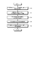
- FIG. 3 is a flow chart explaining the operation flow of the separation system.
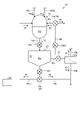
- FIG. 4 is a schematic diagram showing another example of the reaction section.
- FIG. 5 is a partial schematic diagram of the separation system according to the second embodiment.
- FIG. 1 is a schematic diagram of the recycling process of polyethylene terephthalate in this embodiment.
- the PET (polyethylene terephthalate) raw material Pm is depolymerized into a monomer, and the monomer is polymerized again to recycle (regenerate) the PET raw material Pm.
- the PET raw material Pm is flaked (step S100), mixed with a reaction solvent M to depolymerize the PET raw material Pm (step S102), and the depolymerized polyester monomer is purified.
- step S104 to extract monomer D derived from carboxylic acid and monomer E of alcohol component (step S104), hydrolyze monomer D to separate reaction solvent M (step S106), and monomer D is hydrolyzed
- step S106 to separate reaction solvent M
- step S108 monomer D is hydrolyzed
- step S108 The monomer F and the monomer E produced in step S108 are polymerized to regenerate the PET raw material Pm.
- the monomers D and E shown in steps S102 and S104, and the monomer F shown in step S106 are processed without performing the repolymerization process as in step S108. Only the process of recovery may be performed.
- the PET raw material Pm to be depolymerized in the present embodiment is a substance containing PET (polyethylene terephthalate).
- the PET raw material Pm is not limited to containing only the PET component, and also contains components other than the PET component.
- components other than PET contained in the PET raw material Pm include plastics other than PET such as polyethylene, polystyrene, polypropylene, and polyvinyl chloride, metals, pigments, and polymerization catalysts.
- Components other than PET contained in the PET raw material Pm are referred to as impurities R hereinafter.
- reaction solvent M is a solvent that reacts with PET to depolymerize PET.
- Reaction solvent M may be, for example, at least one of methanol, ethanol, water and ethylene glycol.
- Carboxylic acid-derived monomer D is a monomer having a carboxyl group produced by a depolymerization reaction of PET.
- Monomer D may be, for example, dimethyl carboxylate or diethyl carboxylate.
- monomer D is preferably a monomer of terephthalic acid, which may be, for example, dimethyl terephthalate (DMT).
- the alcohol component monomer E is an alcohol component monomer produced by the depolymerization reaction of PET.
- Monomer E can be, for example, a dihydroxy compound (dihydric alcohol), or even ethylene glycol (EG).
- reaction solvent M is methanol
- monomer D is DMT
- monomer E is EG
- FIG. 2 is a schematic diagram of the separation system according to the first embodiment.
- the separation system 1 according to the first embodiment is a system for producing monomers D and E by monomerizing the polyester contained in the PET raw material Pm.
- the separation system 1 includes a raw material storage section 10, a dissolution section 12, a solvent storage section 14, a reaction section 16, a separation section 18, a storage section 20, a removal section 26, a control a portion 30;
- the raw material storage unit 10 is a tank (hopper) into which the PET raw material Pm is introduced and stored. In the present embodiment, flakes of the PET raw material Pm are stored in the raw material storage unit 10, but the shape and size of the PET raw material Pm may be arbitrary.
- the raw material storage section 10 is connected to the dissolving section 12 via an introduction pipe 10a.
- the PET raw material Pm in the raw material storage section 10 is supplied to the dissolving section 12 through the introduction pipe 10a.
- the introduction pipe 10a is provided with an adjusting section 10b for adjusting the amount of the PET raw material Pm supplied from the raw material storage section 10 to the dissolving section 12. As shown in FIG.
- the adjustment unit 10b is, for example, an on-off valve, and when in the open state, supplies the PET raw material Pm in the raw material storage unit 10 to the dissolving unit 12, and in the closed state, allows the PET raw material Pm in the raw material storage unit 10 to flow. The supply to the dissolving section 12 is stopped.
- the adjusting unit 10b is not limited to being an on-off valve, and may be any mechanism capable of adjusting the supply of the PET raw material Pm to the dissolving unit 12 .
- the dissolving part 12 is a tank in which the solution Pd is stored.
- the solution Pd is a solution produced by mixing the PET raw material Pm and the monomer D.
- the PET component contained in the PET raw material Pm is dissolved in the monomer D, but the impurity R, which is a component other than PET contained in the PET raw material Pm, remains without being dissolved in the monomer D. Therefore, it can be said that the solution Pd contains the PET solution P in which the PET contained in the PET raw material Pm is dissolved in the monomer D, and the impurities R contained in the PET raw material Pm.
- the dissolving section 12 is supplied with the monomer D and the PET raw material Pm.
- the PET contained in the PET raw material Pm is dissolved in the monomer D, while the impurity R remains without dissolving in the monomer D, so that the PET solution P and the solution Pd containing the impurity R are generated. .
- the PET solution P is not limited to the state in which the entire amount of PET is dissolved in the monomer D, and at least a part of the PET may be in a state in which the monomer D is not dissolved.
- the PET solution P may also contain the component dissolved in the monomer D.
- the melting section 12 is provided with a heating section 12A.
- the heating section 12A heats the inside of the dissolving section 12 to heat the monomer D and the PET raw material Pm supplied to the dissolving section 12 to a predetermined temperature.
- the predetermined temperature is a temperature at which PET can be dissolved in the monomer D. By heating at a predetermined temperature in this manner, the PET contained in the PET raw material Pm can be dissolved in the monomer D appropriately.
- the predetermined temperature is preferably 140° C. or higher and 300° C. or lower, more preferably 160° C. or higher and 280° C. or lower, and even more preferably 190° C. or higher and 250° C. or lower.
- the impurity R contains a component that melts when heated to a predetermined temperature (the temperature at which PET can be dissolved in the monomer D). Therefore, the impurity R is contained in the solution Pd in a state in which at least a portion thereof is melted.
- the heating section 12A is provided in the dissolving section 12, but the position where the heating section 12A is provided is not limited thereto and is arbitrary.
- the storage part 20 is a tank in which the solution Pd is stored.
- the storage section 20 is connected to the dissolving section 12 via an introduction pipe 12a.
- the solution Pd in the dissolving section 12 is supplied to the storage section 20 through the introduction pipe 12a.
- the introduction pipe 12a is provided with an adjusting portion 12a1 for adjusting the amount of the PET raw material Pm supplied from the dissolving portion 12 to the storing portion 20.
- the adjustment part 12a1 is, for example, an on-off valve, and when it is open, it causes the solution Pd in the dissolving part 12 to be supplied to the storage part 20, and when it is closed, it causes the solution Pd in the dissolution part 12 to be stored. 20 is stopped.
- the adjustment unit 12a1 is not limited to being an on-off valve, and may be any mechanism capable of adjusting the supply of the solution Pd to the storage unit 20.
- the solution Pd is separated into the PET solution P and the impurities R by gravity.
- the PET solution P and the impurities R are separated into the PET solution P and the impurities R by allowing the solution Pd stored in the storage unit 20 to stand still.
- the solution Pd stored in the storage unit 20 is separated by gravity into a layer of the first impurity R1, a layer of the PET solution P, and a layer of the second impurity R2.
- a layer of the first impurity R1 is formed below the layer of the PET solution P in the vertical direction. That is, the first impurity R1 is one of the impurities R that is insoluble in the monomer D and has a higher specific gravity than the PET solution P.
- the first impurity R1 settles in the PET solution P in the reservoir 20 to form a layer of the first impurity R1.
- the layer of the second impurity R2 is formed above the layer of the PET solution P in the vertical direction.
- the second impurity R2 is one of the impurities R that is insoluble in the monomer D and has a lower specific gravity than the PET solution P.
- the second impurity R2 floats in the PET solution P in the reservoir 20 to form a layer of the second impurity R2.
- the solution Pd in the reservoir 20 is maintained at a predetermined temperature (the temperature at which PET can be dissolved in the monomer D) or higher.
- the impurities R the first impurity R1 and the second impurity R2 are components that melt when heated to a predetermined temperature, so they exist in the reservoir 20 in a molten state.
- the first impurity R1 and the second impurity R2 are, for example, plastics other than PET (polyethylene, polystyrene, polypropylene, polyvinyl chloride, etc. other than PET).
- the layer of the PET solution P contains the third impurity R3.
- the third impurity R3 is a component among the impurities R that does not dissolve in the monomer D and does not melt even at a predetermined temperature (the temperature at which PET can dissolve in the monomer D). That is, the third impurity R3 is not separated from the PET solution P even by gravity separation, and exists in the PET solution P in a solid state that does not melt.
- the third impurity R3 is dispersed in the PET solution P in this embodiment.
- the third impurities R3 are, for example, metals, pigments, polymerization catalysts, and the like.
- a discharge pipe 20 a is connected to the reservoir 20 .
- the discharge pipe 20a is a pipe for discharging the first impurity R1 separated from the PET solution P to the lower layer from the reservoir 20. As shown in FIG.
- the discharge pipe 20a is connected to a position where a layer of the first impurities R1 is formed in the reservoir 20, and is connected to the bottom of the reservoir 20 in the example of the present embodiment.
- a first discharge portion 22a is provided in the discharge pipe 20a.
- the first discharge part 22a is a mechanism for discharging the first impurity R1 in the storage part 20 from the storage part 20, and is a pump in this embodiment.
- a discharge pipe 20 b is connected to the reservoir 20 .
- the discharge pipe 20 b is a pipe for discharging the second impurity R 2 separated from the PET solution P to the upper layer from the reservoir 20 .
- the discharge pipe 20b is connected to a position where the layer of the second impurity R2 of the reservoir 20 is formed, and is connected vertically above the discharge pipe 20a.
- the storage part 20 is provided with second discharge parts 22b1 and 22b2 for discharging the second impurities R2 in the storage part 20 from the storage part 20 .
- the second discharge part 22b1 is a skimmer provided at the position of the liquid surface of the PET solution P, and collects (scrapes) the second impurities R2 floating on the liquid surface of the PET solution P.
- the second discharge part 22b2 is a mechanism provided in the discharge pipe 20b to discharge the second impurities R2 collected in the second discharge part 22b1 through the discharge pipe 20b, and is a pump in this embodiment.
- the second discharge units 22b1 and 22b2 are provided as a mechanism for discharging the second impurities R2. It may be arbitrary without being limited to.
- the first impurity R1 and the second impurity R2 separated from the PET solution P in the reservoir 20 are discharged to the outside of the reservoir 20 by the first discharge part 22a and the second discharge parts 22b1 and 22b2. As a result, the first impurity R1 and the second impurity R2 are removed from the PET solution P.
- the first discharge portion 22a and the second discharge portions 22b1 and 22b2 are referred to as the discharge portion 22 when not distinguished from each other.
- the impurity R includes the first impurity R1 having a higher specific gravity than the PET solution P and the second impurity R2 having a lower specific gravity than the PET solution P.
- the impurity R is not limited to this. R may contain only one of the first impurity R1 and the second impurity R2.
- An introduction pipe 20 c is connected to the reservoir 20 .
- the introduction pipe 20 c is a pipe for leading out the PET solution P separated from the impurities R from the reservoir 20 .
- the introduction pipe 20c is connected to a position where a layer of the PET solution P is formed in the reservoir 20, and in the example of the present embodiment, is connected to a position between the discharge pipes 20a and 20b in the vertical direction. ing.
- a lead-out portion 24 is provided in the introduction pipe 20c.
- the lead-out part 24 is a mechanism for leading out the PET solution P in the storage part 20 from the storage part 20, and is a pump in this embodiment.
- the dissolving part 12 that generates the solution Pd and the storage part 20 that separates the solution Pd by gravity are separate tanks.
- the dissolution part 12 and the storage part 20 are not limited to separate tanks, and the solution Pd may be generated and gravity-separated in one tank.
- the storage section 20 also functions as the dissolving section 12 .
- the removal unit 26 is a mechanism for removing the third impurity R3 contained in the PET solution P from the PET solution P. As shown in FIG. The remover 26 is connected to the introduction tube 20c. In this embodiment, as the removing section 26, a first removing section 26a and a second removing section 26b are provided.
- the first removal unit 26a is a filter and collects solid components contained in the PET solution P.
- the second removal section 26b is an adsorption tower, and adsorbs solid components contained in the PET solution P that have not been repaired by the first removal section 26a.
- the second removal section 26b filters solid components contained in the PET solution P that have not been repaired by the first removal section 26a through the packed bed in the packed tower.
- the second removal unit 26b may perform at least one of adsorption of solid components and filtration.
- the PET solution P led out from the storage part 20 to the introduction pipe 20c is introduced into the first removal part 26a, and at least part of the third impurities R3 contained in the PET solution P is trapped in the first removal part 26a. be collected.
- the third impurities R3 collected by the first removal section 26a are discharged to the outside through a discharge pipe 26a1 connected to the first removal section 26a.
- the discharge pipe 26a1 merges with the discharge pipe 20a in the example of FIG. 1, it does not have to merge with the discharge pipe 20a.
- the PET solution P from which at least a portion of the third impurity R3 has been removed by the first removing section 26a is led out from the first removing section 26a and introduced into the second removing section 26b.
- the third impurities R3 remaining in the PET solution P are removed from the PET solution P by being adsorbed or filtered by the second removing section 26b.
- the third impurities R3 adsorbed or filtered by the second removal section 26b are, for example, pigments and polymerization catalysts.
- the PET solution P from which the third impurities R3 have been removed by the second removal section 26b is led out from the second removal section 26b and introduced into the reaction section 16 through the introduction pipe 20c.
- the first removing unit 26a and the second removing unit 26b are provided as a mechanism for removing the third impurities R3 from the PET solution P, but the removing unit 26 for discharging the third impurities R3
- the configuration of is not limited to this and may be arbitrary. Further, since the impurity R may not contain the third impurity R3, the removal section 26 is not an essential component.
- the solvent reservoir 14 is a tank into which the reaction solvent M is introduced and stored.
- the solvent reservoir 14 is connected to the reaction section 16 via an introduction pipe 14a.
- the reaction solvent M in the solvent reservoir 14 is supplied to the reaction section 16 through the introduction pipe 14a.
- the introduction pipe 14a is provided with a heating/pressurizing section 14b that pressurizes and heats the reaction solvent M.
- the heating and pressurizing unit 14b pressurizes and heats the reaction solvent M to bring the reaction solvent M into a supercritical state or a subcritical state (pressurized gas or pressurized liquid).
- a reaction solvent M in a supercritical state or subcritical state is supplied to the reaction section 16 .
- the reaction section 16 is a container into which the PET solution P separated from the impurities R in the storage section 20 and the reaction solvent M are introduced to depolymerize the PET in the PET solution P.
- the reaction section 16 includes a first reaction section 16A and a second reaction section 16B.
- the first reaction section 16A is formed within the reaction section 16 .
- the first reaction section 16A can be said to be a portion of the reaction section 16 filled with a filler.
- known fillers used in gas-liquid or liquid-liquid contact devices can be used. A similar one can be used. Specific examples of fillers include pipes made of SUS or the like, Raschig rings, Berle saddles, terrarets, and the like.
- An introduction pipe 20c is connected to the first reaction section 16A. More specifically, an introduction port 16C, which is an opening through which the PET solution P from the storage section 20 is introduced, of the introduction pipe 20c is connected to the first reaction section 16A.
- the inlet 16C is connected to the surface 16A1 of the first reaction section 16A on the first direction D1 side.
- the introduction pipe 20c is connected to the surface 16A1 such that the introduction port 16C opens toward the second direction D2 opposite to the first direction D1.
- the introduction port 16C that opens toward the second direction D2 is connected to the surface 16A1 of the first reaction section 16A, but it is not limited to this.
- the introduction port 16C does not have to be directly connected to the first reaction section 16A, and the introduction port 16C that opens toward the second direction D2 is connected to the surface 16A1 of the first reaction section 16A in the reaction section 16. may be connected to the side of the first direction D1.
- An introduction pipe 14 a is connected to the reaction section 16 . More specifically, the reaction section 16 is connected to an introduction port 16D, which is an opening through which the reaction solvent M from the solvent storage section 14 is introduced, of the introduction pipe 14a.
- the inlet 16D is connected to the second direction D2 side of the surface 16A2 of the first reaction section 16A on the second direction D2 side.
- the introduction pipe 14a is connected to the second direction D2 side of the surface 16A2 so that the introduction port 16D opens toward the first direction D1 side or toward the center side from the side surface.
- the introduction port 16D which opens toward the first direction D1 side or toward the center from the side surface, is connected to the second direction D2 side of the surface 16A2 of the first reaction portion 16A.
- the inlet 16D may be directly connected to the first reaction section 16A, or may be connected to the surface 16A2 of the first reaction section 16A.
- the introduction port 16C through which the PET solution P is introduced faces the second direction D2
- the introduction port 16D through which the reaction solvent M is introduced faces the first direction D1, Or open from the side toward the center. Therefore, the PET solution P and the reaction solvent M are introduced into the first reaction section 16A in directions facing each other.
- the PET solution P introduced into the first reaction section 16A from the inlet 16C moves in the second direction D2 on the surface of the filler of the first reaction section 16A.
- the reaction solvent M in the supercritical state or subcritical state (pressurized gas or pressurized liquid) introduced from the inlet 16D moves in the first direction D1 in the first reaction section 16A.
- the reaction solvent M in a supercritical state or subcritical state contacts the PET solution P in the first reaction section 16A.
- the PET in the PET solution P is depolymerized (reduced in molecular weight) by the reaction solvent M, and the depolymerized PET is extracted into the reaction solvent M in a supercritical or subcritical state (pressurized gas or pressurized liquid). be done.
- the PET depolymerized in the first reaction section 16A is referred to as the first depolymerized polyester P1
- Solvent M is described as first solvent M1.
- the first solvent M1 containing the first depolymerized polyester P1 advances through the first reaction section 16A in the first direction D1 and is led out of the first reaction section 16A toward the first direction D1.
- the first depolymerized polyester P1 is composed of monomers D and E generated by depolymerizing PET in the PET solution P, monomer D originally mixed in the PET solution P, and PET depolymerized. and an oligomer produced by Here, the oligomer is not monomerized, but can be said to be a carboxylic acid-derived or alcohol component oligomer depolymerized from PET (a carboxylic acid-derived or alcohol component oligomer having a molecular weight smaller than that of PET).
- the second reaction section 16B is formed within the reaction section 16, and the second reaction section 16B is formed at a location where the first solvent M1 is led out from the first reaction section 16A.
- the second reaction section 16B can be said to be a space formed on the first direction D1 side of the first reaction section 16A.
- the first depolymerized polyester P1 contained in the first solvent M1 is further depolymerized (reduced in molecular weight) by the reaction solvent M contained in the first solvent M1.
- the first depolymerized polyester P1 further depolymerized in the second reaction section 16B is referred to as a second depolymerized polyester P2, and a mixture of the second depolymerized polyester P2 and the reaction solvent M (second depolymerized polyester
- the reaction solvent M) in which PE is dissolved is described as the second solvent M2.
- a lead-out pipe 16a is connected to the second reaction section 16B.
- the outlet port 16E which is an opening through which the second solvent M2 from the second reaction section 16B is led out, of the outlet pipe 16a is connected to the second reaction section 16B.
- the second solvent M2 containing the second depolymerized polyester P2 in the second reaction section 16B is discharged out of the second reaction section 16B from the discharge port 16E through the discharge pipe 16a.
- the second depolymerized polyester P2 includes the monomers D and E in the first depolymerized polyester P1, the monomers D and E generated by depolymerizing the oligomers in the first depolymerized polyester P1, and the 1 and an oligomer produced by depolymerizing the depolymerized polyester P1.
- a discharge pipe 16 b is connected to the bottom of the reaction section 16 . More specifically, the bottom of the reaction section 16 is connected to a discharge port 16F, which is an opening through which non-extracted substances (described later) in the reaction section 16 are discharged from the discharge pipe 16b. From the outlet 16F, non-extractable substances including impurities such as metal compounds not extracted with the reaction solvent M and residues of undecomposed polyester not extracted with the reaction solvent M are discharged. That is, the non-extractable matter at the bottom of the reaction section 16 is discharged outside the reaction section 16 from the discharge port 16F through the discharge pipe 16b.
- the non-extractable matter discharged from the discharge port 16F is not led to the separation unit 18 as the second solvent M2 (the reaction solvent M in which the second depolymerized polyester P2 is dissolved), and is used in the first reaction. It can be said that this is a component remaining in the portion 16A and the second reaction portion 16B.
- the reaction section 16 may be provided with a heating section that heats the inside of the reaction section 16 and a pressure section that keeps the pressure inside the reaction section 16 at a predetermined value or higher.
- the temperature inside the reaction section 16 is preferably 250° C. or higher and 400° C. or lower, and more preferably 250° C. or higher and 350° C. or lower.
- the pressure inside the reaction section 16 is preferably 1 MPa or more and 30 MPa or less, more preferably 6 MPa or more and 25 MPa or less.
- the pressure section and the heating section may be controlled by the control section 30 .
- the second solvent M2 containing the second depolymerized polyester P2 is introduced into the separation unit 18, and the second solvent M2 is divided into the reaction solvent M, the carboxylic acid-derived monomer D contained in the second depolymerized polyester P2, The alcohol component monomer E contained in the second depolymerized polyester P2 and the residual substance are separated.
- the residual substance is a component of the second solvent M2 other than the reaction solvent M, the monomer D, and the monomer E, and includes an oligomer.
- the separation section 18 has a first separation section 18A, a second separation section 18B, and a third separation section 18C.
- the first separation section 18A is a separation tower connected to the outlet pipe 16a.
- the second solvent M2 containing the second depolymerized polyester P2 is introduced into the first separation section 18A through the outlet pipe 16a.
- the first separation section 18A separates the second solvent M2 into a low boiling point component and a high boiling point component having a boiling point higher than that of the low boiling point component.
- the second solvent M2 may be set to a predetermined temperature
- the gaseous component may be the low boiling point component
- the liquid component may be the high boiling point component.
- Outlet pipes 18Aa and 18Ab are connected to the first separating portion 18A. A low boiling point component is discharged from the discharge pipe 18Aa, and a high boiling point component is discharged from the discharge pipe 18Ab.
- the second separation section 18B is a separation tower connected to the first separation section 18A via an outlet pipe 18Aa.
- a low boiling point component is introduced into the second separation section 18B via the lead-out pipe 18Aa.
- the second separation section 18B separates the low boiling point component into the reaction solvent M and the monomer E.
- Lead-out pipes 18Ba and 18Bb are connected to the second separating portion 18B.
- the reaction solvent M is discharged from the discharge pipe 18Ba, and the monomer E is discharged from the discharge pipe 18Bb.
- the lead-out pipe 18Ba is connected to the second separation section 18B and the solvent storage section 14. As shown in FIG. Therefore, the reaction solvent M drawn out from the second separation section 18B is returned to the solvent storage section 14 and reused for PET monomerization.
- the third separation section 18C is a separation tower connected to the first separation section 18A via an outlet pipe 18Ab.
- a high boiling point component is introduced into the third separation section 18C via the outlet pipe 18Ab.
- the third separation section 18C further separates the high boiling point component into a high boiling point residual substance, a low boiling point component including the reaction solvent M and the monomer E, and the monomer D.
- Outlet pipes 18Ca, 18Cb, and 18Cc are connected to the third separating portion 18C.
- the lead-out pipe 18Ca is connected to the second separation section 18B.
- the low boiling point components separated in the third separation section 18C are led out to the second separation section 18B via the lead-out pipe 18Ca.
- the monomer D separated in the third separating section 18C is discharged from the outlet pipe 18Cb, and the residual substance separated in the third separating section 18C is discharged from the outlet pipe 18Cc.
- An introduction pipe 18Cd is connected to the third separating portion 18C.
- the introduction pipe 18Cd is also connected to the dissolution section 12 and introduces the monomer D drawn out from the third separation section 18C into the dissolution section 12 .
- the introduction pipe 18Cd branches off from the outlet pipe 18Cb.
- the introduction pipe 18Cd is provided with an adjusting section 18Ce that adjusts the amount of the monomer D supplied from the third separating section 18C to the dissolving section 12 .
- the adjusting section 18Ce is, for example, an on-off valve, which supplies the monomer D to the dissolving section 12 when in the open state, and stops the supply of the monomer D to the dissolving section 12 when in the closed state.
- the adjustment section 18Ce is not limited to being an on-off valve, and may be any mechanism capable of adjusting the supply of the monomer D to the dissolving section 12 .
- the adjustment section 18Ce is provided at a branch point of the introduction tube 18Cd from the outlet tube 18Cb, but the location of the adjustment section 18Ce is not limited to this and may be arbitrary.
- the introduction pipe 18Cd may not be connected to the outlet pipe 18Cb, and may be directly connected to the third separation section 18C.
- the lead-out pipe 18Cb may be provided with a storage portion (tank) for storing the monomer D, and the introduction pipe 18Cd may be connected to the storage portion.
- At least part of the residual substance may be introduced into the dissolving section 12 by connecting the lead-out pipe 18Cc to the dissolving section 12 .
- the oligomer contained in the residual substance can be depolymerized again in the reaction section 16, and the yield of the monomer can be improved.
- the control unit 30 is a control device that controls the separation system 1 .
- the control unit 30 controls the adjusting unit 10 b to control the amount of the polyester raw material PE supplied from the raw material storage unit 10 to the dissolving unit 12 .
- the control unit 30 controls the adjustment unit 12 a 1 to control the amount of the solution Pd supplied from the dissolving unit 12 to the storage unit 20 .
- the control unit 30 controls the discharge unit 22 to discharge the impurities R separated from the PET solution P in the storage unit 20 from the storage unit 20 .
- the control unit 30 controls the lead-out unit 24 to lead out the PET solution P separated from the impurities R in the storage unit 20 from the storage unit 20 and controls the amount of the PET solution P to be introduced into the reaction unit 16 .
- the control unit 30 controls the heating/pressurizing unit 14b to bring the reaction solvent M into a supercritical state or subcritical state (pressurized gas or pressurized liquid), and the supercritical state or subcritical state (pressurized gas or pressurized liquid).
- the supply amount of the reaction solvent M (liquid) to the reaction section 16 is controlled.
- the control unit 30 controls the amount of monomer D supplied to the dissolving unit 12 by controlling the adjusting unit 18Ce.
- the control unit 30 is a computer in this embodiment, and includes a processor including an arithmetic circuit such as a CPU (Central Processing Unit), and a storage unit that stores various information such as the content of arithmetic operations performed by the processor and programs.
- the control unit 30 executes control of the separation system 1 by reading the program from the storage unit.
- the separation system 1 is not limited to being automatically controlled by the control unit 30, and for example, at least part of the processing may be controlled by an operator.
- the control unit 30 controls the adjusting units 10b and 18Ce to introduce the PET raw material Pm and the monomer D into the dissolving unit 12, mix the PET raw material Pm and the monomer D in the dissolving unit 12, and dissolve them. Liquid Pd is produced.
- the control unit 30 controls the adjusting unit 12 a 1 to introduce the solution Pd generated in the dissolving unit 12 into the storage unit 20 .
- the solution Pd introduced into the reservoir 20 is separated by gravity into a layer of the first impurity R1, a layer of the PET solution P, and a layer of the second impurity R2 by being left still for a predetermined time. be. Any method may be used to allow the solution Pd to stand still.
- the control unit 30 may stop the discharge unit 22 and the lead-out unit 24 to leave the solution Pd still.
- the control unit 30 controls the discharge unit 22 to discharge the first impurities R1 and the second impurities R2 in the storage unit 20, and controls the lead-out unit 24 to store the PET solution P in the storage unit 20. Let it be derived from the part 20 .
- the removal unit 26 removes the third impurities R3 from the PET solution P drawn out from the storage unit 20, and the PET solution P is introduced into the first reaction unit 16A.
- the control unit 30 controls the heating and pressurizing unit 14 b to supply the reaction solvent M in a supercritical state or subcritical state (pressurized gas or pressurized liquid) to the reaction unit 16 .
- the control unit 30 sets the reaction solvent M to preferably 250° C. or higher and 400° C. or lower, more preferably 250° C. or higher and 350° C. or lower.
- the control unit 30 sets the reaction solvent M to preferably 1 MPa or more and 30 MPa or less, more preferably 6 MPa or more and 25 MPa or less.
- the PET contained in the PET solution P is depolymerized in the first reaction section 16A to produce the first depolymerized polyester P1.
- the first depolymerized polyester P1 is further depolymerized to generate a second solvent M2, which is a mixture of the second depolymerized polyester P2 and the reaction solvent M.
- the second solvent M2 is separated into the reaction solvent M, the monomer D, the monomer E, and the residual substance in the first separation section 18A, the second separation section 18B, and the third separation section 18C.
- the monomers D and E are recovered from the polyester raw material PE, and by polymerizing them, the polyester raw material PE can be regenerated.
- FIG. 3 is a flow chart explaining the operation flow of the separation system.
- the control section 30 introduces the PET raw material Pm and the monomer D into the dissolving section 12 to generate the dissolving liquid Pd (step S10).
- the control unit 30 supplies the solution Pd to the storage unit 20 and separates the solution Pd into the first impurity R1, the second impurity R2, and the PET solution P by gravity (step S12).
- the control unit 30 discharges the first impurity R1, the second impurity R2, and the PET solution P from the storage unit 20 (step S14), and causes the removal unit 26 to remove the third impurity R3 from the PET solution P (step S16). ). Then, the control unit 30 introduces the PET solution P and the reaction solvent M into the reaction unit 16 to depolymerize the PET in the PET solution P (step S18).
- the PET raw material Pm may contain impurities R other than PET, and the impurities R must be removed in order to depolymerize and recycle PET.
- the impurity R may exist as a highly viscous melt, it may block the opening of the filter of the filter, making it impossible to collect and separate the impurity R properly.
- the solution Pd is separated into the PET solution P and the impurities R by gravity separation. Then, the impurities R separated by gravity are discharged, and the PET solution P separated by gravity is used for depolymerization.
- the impurities R can be appropriately recovered without clogging the opening of the filter of the filter, and the PET and the foreign matter can be appropriately separated.
- the PET solution P is depolymerized after the impurities R are separated by gravity. Therefore, the depolymerization can be performed while the purity of the PET is increased during the depolymerization, and the yields of the monomers D and E can be improved.
- the impurities R may contain a polymerization catalyst. Since the polymerization catalyst is a catalyst that promotes polymerization, it may inhibit depolymerization. In contrast, in the present embodiment, the depolymerization is performed after the polymerization catalyst is also removed, so the depolymerization can be appropriately performed and the yields of the monomers D and E can be improved. Furthermore, when depolymerization is performed by adding a depolymerization catalyst, the amount of the depolymerization catalyst added can be reduced by the amount of the removal of the polymerization catalyst.
- FIG. 4 is a schematic diagram showing another example of the reaction section.
- the reaction section 16 may have a double-tube structure, the inner tube portion being the first reaction section 16Ab, and the outer tube portion being the second reaction section 16Bb.
- the inlet 16Cb for the PET solution P and the inlet 16Db for the reaction solvent M are opened in the second direction D2 and connected to the surface of the first reaction section 16Ab on the first direction D1 side.
- the PET solution P and the reaction solvent M are supplied in the second direction D2, that is, in the same direction.
- the PET solution P and the reaction solvent M proceed in the second direction D2 while reacting in the first reaction section 16Ab, and the first solvent M1 (the reaction solvent M from which the first depolymerized polyester P1 has been extracted) is used as the first solvent M1.
- the non-extracted matter is discharged from a discharge port 16Fb that opens at the bottom of the reaction section 16 .
- the configuration of the reaction section 16 that depolymerizes PET is not limited to the above description and may be arbitrary.
- the reaction section 16 may not have a two-stage configuration of the first reaction section 16A and the second reaction section 16B.
- the configuration of the separation unit 18 for separating the monomers D, E, etc. is not limited to the above description and may be arbitrary.
- methanol was used as the reaction solvent M for depolymerizing PET, but the reaction solvent M is not limited to methanol, and may be ethylene glycol or the like as described above.
- the second embodiment differs from the first embodiment in that at least part of the first impurity R1 and the second impurity R2 is returned to the solution Pd.
- the second embodiment descriptions of parts having the same configuration as in the first embodiment are omitted.
- FIG. 5 is a partial schematic diagram of the separation system according to the second embodiment.
- the separation system 1A according to the second embodiment has an introduction section 29 that introduces at least part of the first impurities R1 and the second impurities R2 into the solution Pd.
- an introduction pipe 20a1 that connects the storage section 20 and the dissolution section 12 is provided.
- the introduction pipe 20 a 1 is a pipe that branches from the discharge pipe 20 a and connects the discharge pipe 20 a and the dissolving section 12 .
- the introduction pipe 20a1 is provided with an introduction portion 29a for adjusting the amount of the first impurity R1 introduced from the storage portion 20 into the dissolution portion 12.
- the introduction part 29a is, for example, an on-off valve, which allows the first impurity R1 to be supplied to the dissolving part 12 when in the open state, and stops the supply of the first impurity R1 to the dissolving part 12 when in the closed state.
- the introduction part 29 a is not limited to being an on-off valve, and may be any mechanism capable of adjusting the supply of the first impurity R ⁇ b>1 to the dissolving part 12 .
- the introduction part 29a is provided at a branching point of the introduction pipe 20a1 from the discharge pipe 20a, but the position of the introduction part 29a is not limited thereto and may be arbitrary.
- the introduction pipe 20a1 is not limited to being branched from the discharge pipe 20a, and may be directly connected to the storage section 20 and the dissolving section 12.
- an introduction pipe 20b1 that connects the storage section 20 and the dissolving section 12 is provided.
- the introduction pipe 20 b 1 is a pipe that branches from the discharge pipe 20 b and connects the discharge pipe 20 b and the dissolving section 12 .
- the introduction pipe 20b1 is provided with an introduction portion 29b for adjusting the amount of the second impurity R2 introduced from the storage portion 20 into the dissolution portion 12.
- the introduction part 29b is, for example, an on-off valve, which allows the second impurity R2 to be supplied to the dissolving part 12 when in the open state, and stops the supply of the second impurity R2 to the dissolving part 12 when in the closed state.
- the introducing part 29b is not limited to being an on-off valve, and may be any mechanism capable of adjusting the supply of the second impurity R2 to the dissolving part 12.
- the introduction part 29b is provided at a branching point of the introduction pipe 20b1 from the discharge pipe 20b, but the position of the introduction part 29b is not limited thereto and may be arbitrary.
- the introduction pipe 20b1 is not limited to being branched from the discharge pipe 20b, and may be directly connected to the storage section 20 and the dissolving section 12.
- the control unit 30 introduces the PET raw material Pm and the monomer D into the dissolution unit 12 to generate the solution Pd, and controls the introduction units 29a and 29b to remove the first impurity R1 and the second impurity R1 in the storage unit 20. At least part of the two impurities R2 is introduced into the dissolution section 12 .
- the first impurity R1 and the second impurity R2 from the reservoir 20 are added to the solution Pd produced by mixing the PET raw material Pm and the monomer D, so that the first impurity R1 in the solution Pd and the concentration of the second impurity R2 is improved.
- the control unit 30 introduces the solution Pd in which the concentrations of the first impurities R1 and the second impurities R2 are thus improved into the storage unit 20 to form a layer of the first impurities R1, a layer of the PET solution P, A layer of the second impurity R2 is separated by gravity.
- the separated first impurities R1 and second impurities R2 are discharged from the discharge pipes 20a and 20b, but when part of the PET solution P is discharged together with the first impurities R1 and second impurities R2 There is When the concentrations of the first impurities R1 and the second impurities R2 are low, the amount of the PET solution P discharged together with the first impurities R1 and the second impurities R2 increases. Since the concentrations of the first impurity R1 and the second impurity R2 are increased, the amount of the PET solution P to be discharged can be reduced, and as a result, the yields of the monomers D and E can be improved.
- the process of separating the first impurities R1 and the second impurities R2 in the storage part 20 and returning them to the dissolving part 12 is performed a predetermined number of times, thereby returning the first impurities R1 and R2 to the dissolving part 12. It is preferable to secure a sufficient amount of the second impurity R2. Thereby, the concentrations of the first impurity R1 and the second impurity R2 in the solution Pd can be appropriately increased.
- the separation system 1 has the storage section 20, the discharge section 22, and the reaction section 16.
- the reservoir 20 stores a PET solution P in which PET is dissolved in a carboxylic acid-derived monomer D, and a solution Pd containing impurities R that are components other than PET. and impurity R.
- the discharge part 22 discharges the separated impurities R from the storage part 20 .
- the reaction unit 16 receives the separated PET solution P and a reaction solvent M that reacts with PET, and depolymerizes the PET in the PET solution P.
- the separation system 1 separates the solution Pd into a PET solution P and impurities R by gravity separation. Then, the impurities R separated by gravity are discharged, and the PET solution P separated by gravity is used for depolymerization. As a result, when separating the impurities R, the opening of the filter of the filter is not clogged by the impurities R, and the PET and the impurities R (foreign matter) can be separated appropriately. In addition, since the PET solution P from which the impurity R is removed is depolymerized, it is possible to depolymerize the PET in a state of high purity, and the yield of the monomers D and E can be improved.
- the discharge unit 22 includes a first discharge unit 22a for discharging first impurities R1, which are impurities R separated into a lower layer than the PET solution P in the storage unit 20, and impurities R separated into an upper layer than the PET solution. and a second discharge portion 22b2 for discharging certain second impurities R2.
- first impurities R1 which are impurities R separated into a lower layer than the PET solution P in the storage unit 20, and impurities R separated into an upper layer than the PET solution.
- a second discharge portion 22b2 for discharging certain second impurities R2.
- the separation system 1A further has an introduction part 29 that introduces at least part of the first impurities R1 and the second impurities R2 into the solution Pd.
- introduction part 29 that introduces at least part of the first impurities R1 and the second impurities R2 into the solution Pd.
- the separation system 1 further includes a removal section 26 that removes from the PET solution P the third impurities R3, which are the impurities R present in the PET solution P. According to the present disclosure, removing the third impurity R3 that was not separated by gravity separation can increase the purity of PET in the PET solution P and improve the yield of monomers D and E.
- the separation system 1 further has a dissolution section 12 into which the PET raw material Pm containing PET and the carboxylic acid-derived monomer D are introduced to generate a dissolution liquid Pd. Then, the solution Pd is introduced from the dissolving section 12 . According to the present disclosure, it is possible to properly separate PET and impurities R (foreign matter).
- the reaction solvent M is methanol
- the carboxylic acid-derived monomer D is dimethyl terephthalate. According to the present disclosure, by dissolving PET in dimethyl terephthalate, the fluidity of PET can be increased, and PET can be easily introduced into reaction section 16 . Also, by reacting PET with methanol, PET can be appropriately depolymerized.
- the embodiment of the present invention has been described above, the embodiment is not limited by the content of this embodiment.
- the components described above include those that can be easily assumed by those skilled in the art, those that are substantially the same, and those within the so-called equivalent range.
- the components described above can be combined as appropriate.
- various omissions, replacements, or modifications of components can be made without departing from the gist of the above-described embodiments.
Landscapes
- Chemical & Material Sciences (AREA)
- Chemical Kinetics & Catalysis (AREA)
- Organic Chemistry (AREA)
- Medicinal Chemistry (AREA)
- Life Sciences & Earth Sciences (AREA)
- Sustainable Development (AREA)
- Health & Medical Sciences (AREA)
- Polymers & Plastics (AREA)
- Engineering & Computer Science (AREA)
- Environmental & Geological Engineering (AREA)
- Mechanical Engineering (AREA)
- Separation, Recovery Or Treatment Of Waste Materials Containing Plastics (AREA)
- Separation Of Solids By Using Liquids Or Pneumatic Power (AREA)
- Extraction Or Liquid Replacement (AREA)
Priority Applications (3)
| Application Number | Priority Date | Filing Date | Title |
|---|---|---|---|
| EP22815574.3A EP4324873A4 (en) | 2021-05-31 | 2022-02-18 | SEPARATION SYSTEM AND SEPARATION PROCESS |
| US18/565,006 US20240254308A1 (en) | 2021-05-31 | 2022-02-18 | Separation system and separation method |
| MX2023013959A MX2023013959A (es) | 2021-05-31 | 2022-02-18 | Sistema de separacion y metodo de separacion. |
Applications Claiming Priority (2)
| Application Number | Priority Date | Filing Date | Title |
|---|---|---|---|
| JP2021-091776 | 2021-05-31 | ||
| JP2021091776A JP7377834B2 (ja) | 2021-05-31 | 2021-05-31 | 分離システム及び分離方法 |
Publications (1)
| Publication Number | Publication Date |
|---|---|
| WO2022254815A1 true WO2022254815A1 (ja) | 2022-12-08 |
Family
ID=84324189
Family Applications (1)
| Application Number | Title | Priority Date | Filing Date |
|---|---|---|---|
| PCT/JP2022/006714 Ceased WO2022254815A1 (ja) | 2021-05-31 | 2022-02-18 | 分離システム及び分離方法 |
Country Status (5)
| Country | Link |
|---|---|
| US (1) | US20240254308A1 (https=) |
| EP (1) | EP4324873A4 (https=) |
| JP (1) | JP7377834B2 (https=) |
| MX (1) | MX2023013959A (https=) |
| WO (1) | WO2022254815A1 (https=) |
Families Citing this family (1)
| Publication number | Priority date | Publication date | Assignee | Title |
|---|---|---|---|---|
| JP2025098579A (ja) * | 2023-12-20 | 2025-07-02 | 三菱重工業株式会社 | モノマー製造システム、制御方法及びプログラム |
Citations (7)
| Publication number | Priority date | Publication date | Assignee | Title |
|---|---|---|---|---|
| JPH08325407A (ja) * | 1995-05-08 | 1996-12-10 | Shell Internatl Res Maatschappij Bv | ポリエチレンテレフタレートを含む混合ポリマーのリサイクル方法 |
| JP2000297178A (ja) * | 1999-04-13 | 2000-10-24 | Teijin Ltd | テレフタル酸ジメチルの回収方法 |
| JP2001522387A (ja) * | 1997-04-18 | 2001-11-13 | デュポン テイジン フィルムズ ユー.エス.リミテッド パートナーシップ | 汚染ポリエステル廃棄物からのポリエステルの回収 |
| JP2002086448A (ja) * | 2000-09-13 | 2002-03-26 | Mitsubishi Heavy Ind Ltd | ポリエステルの再生方法 |
| JP4065659B2 (ja) | 2000-11-30 | 2008-03-26 | 帝人ファイバー株式会社 | ポリエチレンテレフタレート廃棄物からの有効成分回収方法 |
| US20180361356A1 (en) * | 2015-12-18 | 2018-12-20 | Solvay Sa | Use of a catalyst composition for the catalytic depolymerization of plastics waste |
| US20200102441A1 (en) * | 2017-06-16 | 2020-04-02 | Green Union S.R.L. | Treatment plant and method for pet glycolysis |
Family Cites Families (7)
| Publication number | Priority date | Publication date | Assignee | Title |
|---|---|---|---|---|
| US5298530A (en) * | 1992-11-25 | 1994-03-29 | Eastman Kodak Company | Process of recovering components from scrap polyester |
| JPH07286061A (ja) * | 1993-07-15 | 1995-10-31 | Teijin Ltd | アラミドドープの製造法及びそれを用いるフィブリッドの製造法 |
| JP4005301B2 (ja) * | 2000-08-17 | 2007-11-07 | 帝人ファイバー株式会社 | ポリエステル廃棄物からの有効成分回収方法 |
| JP4008214B2 (ja) * | 2001-08-03 | 2007-11-14 | 三菱重工業株式会社 | ポリエステルのモノマー化反応容器 |
| JP2005002161A (ja) * | 2003-06-10 | 2005-01-06 | Teijin Fibers Ltd | 異種プラスチックの除去方法 |
| JP2005014279A (ja) * | 2003-06-24 | 2005-01-20 | Teijin Fibers Ltd | 異種プラスチックの分離方法 |
| KR20220041177A (ko) * | 2019-07-29 | 2022-03-31 | 이스트만 케미칼 컴파니 | 열분해 및 가메탄올분해로부터의 재활용된 단량체를 갖는 폴리에스테르의 제조 방법 |
-
2021
- 2021-05-31 JP JP2021091776A patent/JP7377834B2/ja active Active
-
2022
- 2022-02-18 EP EP22815574.3A patent/EP4324873A4/en active Pending
- 2022-02-18 MX MX2023013959A patent/MX2023013959A/es unknown
- 2022-02-18 WO PCT/JP2022/006714 patent/WO2022254815A1/ja not_active Ceased
- 2022-02-18 US US18/565,006 patent/US20240254308A1/en active Pending
Patent Citations (7)
| Publication number | Priority date | Publication date | Assignee | Title |
|---|---|---|---|---|
| JPH08325407A (ja) * | 1995-05-08 | 1996-12-10 | Shell Internatl Res Maatschappij Bv | ポリエチレンテレフタレートを含む混合ポリマーのリサイクル方法 |
| JP2001522387A (ja) * | 1997-04-18 | 2001-11-13 | デュポン テイジン フィルムズ ユー.エス.リミテッド パートナーシップ | 汚染ポリエステル廃棄物からのポリエステルの回収 |
| JP2000297178A (ja) * | 1999-04-13 | 2000-10-24 | Teijin Ltd | テレフタル酸ジメチルの回収方法 |
| JP2002086448A (ja) * | 2000-09-13 | 2002-03-26 | Mitsubishi Heavy Ind Ltd | ポリエステルの再生方法 |
| JP4065659B2 (ja) | 2000-11-30 | 2008-03-26 | 帝人ファイバー株式会社 | ポリエチレンテレフタレート廃棄物からの有効成分回収方法 |
| US20180361356A1 (en) * | 2015-12-18 | 2018-12-20 | Solvay Sa | Use of a catalyst composition for the catalytic depolymerization of plastics waste |
| US20200102441A1 (en) * | 2017-06-16 | 2020-04-02 | Green Union S.R.L. | Treatment plant and method for pet glycolysis |
Non-Patent Citations (1)
| Title |
|---|
| See also references of EP4324873A4 |
Also Published As
| Publication number | Publication date |
|---|---|
| US20240254308A1 (en) | 2024-08-01 |
| EP4324873A4 (en) | 2025-05-07 |
| JP2022184117A (ja) | 2022-12-13 |
| MX2023013959A (es) | 2023-12-11 |
| EP4324873A1 (en) | 2024-02-21 |
| JP7377834B2 (ja) | 2023-11-10 |
Similar Documents
| Publication | Publication Date | Title |
|---|---|---|
| US5298530A (en) | Process of recovering components from scrap polyester | |
| CN116583557A (zh) | 通过溶解聚合物和通过吸附纯化来处理废塑料的方法 | |
| CN103360260A (zh) | 一种对苯二甲酸乙二酯的制备工艺和聚酯的制备方法 | |
| WO2022254815A1 (ja) | 分離システム及び分離方法 | |
| TW202428736A (zh) | 藉由於溶劑中溶解並逐步引入溶劑以回收及處理舊塑料之方法 | |
| JP7720173B2 (ja) | モノマー製造システム及びモノマー製造方法 | |
| WO2024063098A1 (ja) | 分離システム及び分離方法 | |
| JP4564295B2 (ja) | 気泡塔型反応器を用いた酢酸製造方法 | |
| JP4647413B2 (ja) | 生分解性ポリエステルの解重合方法 | |
| JP2025523422A (ja) | 軽質炭化水素溶媒を用いるポリエチレンをベースとする使用済みプラスチックのリサイクル方法 | |
| TW202409167A (zh) | 使用輕烴溶劑回收基於聚丙烯之舊塑料之方法 | |
| JP2025520375A (ja) | 軽質炭化水素溶媒を用いた使用済みプラスチックのリサイクル方法 | |
| TWI923322B (zh) | 晶析系統、晶析方法及程式 | |
| US5747547A (en) | Recovery of components from polyester resins | |
| JP2025153006A (ja) | 洗浄装置、分離システム及び洗浄方法 | |
| WO2025164051A1 (ja) | 加水分解反応システム及び制御方法 | |
| WO2025258120A1 (ja) | 晶析システム、晶析方法及びプログラム | |
| WO2025146748A1 (ja) | 晶析システム及び晶析方法 | |
| JP2025100033A (ja) | 濃度測定装置、分離システム及び濃度測定方法 | |
| WO2025134861A1 (ja) | 反応器、及びモノマー製造システム | |
| JP2026510330A (ja) | デカンテーションによるポリマー溶液からの不純物の分離を含むプラスチックのリサイクル方法 | |
| JP2005068039A (ja) | 芳香族ジカルボン酸エステルの回収方法 | |
| JP2003300929A (ja) | Petからモノマーの製造方法 | |
| CN120958073A (zh) | 用于制备再生的聚合物的方法 |
Legal Events
| Date | Code | Title | Description |
|---|---|---|---|
| 121 | Ep: the epo has been informed by wipo that ep was designated in this application |
Ref document number: 22815574 Country of ref document: EP Kind code of ref document: A1 |
|
| WWE | Wipo information: entry into national phase |
Ref document number: 202317076570 Country of ref document: IN |
|
| WWE | Wipo information: entry into national phase |
Ref document number: 2022815574 Country of ref document: EP |
|
| ENP | Entry into the national phase |
Ref document number: 2022815574 Country of ref document: EP Effective date: 20231115 |
|
| WWE | Wipo information: entry into national phase |
Ref document number: MX/A/2023/013959 Country of ref document: MX |
|
| WWE | Wipo information: entry into national phase |
Ref document number: 2301007752 Country of ref document: TH |
|
| WWE | Wipo information: entry into national phase |
Ref document number: 18565006 Country of ref document: US |
|
| NENP | Non-entry into the national phase |
Ref country code: DE |