WO2022254652A1 - 電機機器の引出し装置およびスイッチギヤ - Google Patents
電機機器の引出し装置およびスイッチギヤ Download PDFInfo
- Publication number
- WO2022254652A1 WO2022254652A1 PCT/JP2021/021187 JP2021021187W WO2022254652A1 WO 2022254652 A1 WO2022254652 A1 WO 2022254652A1 JP 2021021187 W JP2021021187 W JP 2021021187W WO 2022254652 A1 WO2022254652 A1 WO 2022254652A1
- Authority
- WO
- WIPO (PCT)
- Prior art keywords
- opening
- plate
- electrical equipment
- shielding plate
- side plate
- Prior art date
- Legal status (The legal status is an assumption and is not a legal conclusion. Google has not performed a legal analysis and makes no representation as to the accuracy of the status listed.)
- Ceased
Links
Images

Classifications
-
- H—ELECTRICITY
- H02—GENERATION; CONVERSION OR DISTRIBUTION OF ELECTRIC POWER
- H02B—BOARDS, SUBSTATIONS OR SWITCHING ARRANGEMENTS FOR THE SUPPLY OR DISTRIBUTION OF ELECTRIC POWER
- H02B11/00—Switchgear having carriage withdrawable for isolation
- H02B11/18—Switchgear having carriage withdrawable for isolation with isolation by vertical withdrawal
- H02B11/20—Switchgear having carriage withdrawable for isolation with isolation by vertical withdrawal having an enclosure
- H02B11/22—Switchgear having carriage withdrawable for isolation with isolation by vertical withdrawal having an enclosure wherein front of enclosure moves with carriage upon horizontal withdrawal subsequent to isolation
-
- H—ELECTRICITY
- H02—GENERATION; CONVERSION OR DISTRIBUTION OF ELECTRIC POWER
- H02B—BOARDS, SUBSTATIONS OR SWITCHING ARRANGEMENTS FOR THE SUPPLY OR DISTRIBUTION OF ELECTRIC POWER
- H02B11/00—Switchgear having carriage withdrawable for isolation
- H02B11/24—Shutters or guards
Definitions
- This application relates to drawers and switch gears for electrical equipment.
- the high-voltage compartment of a metal-enclosed switchgear consists of a circuit breaker compartment, a busbar compartment, a connection compartment, etc. Each compartment is provided with a partition plate to separate it from other compartments. Electrical equipment such as circuit breakers, instrument transformers, lightning arresters, and zero-phase voltage detection capacitors may have a structure that allows them to be pulled out for maintenance and inspection. In the inspection of a compartment in which drawable electric equipment is arranged, the electric equipment is pulled out from the switchgear using the drawer device for the electric equipment, and the inspection is carried out.
- the compartment that stores electrical equipment that can be pulled out is classified as a high-voltage compartment, and is equipped with a metal partition plate to prevent the operator from touching the high-voltage charging part during inspection, in order to prevent electric shock to the operator during inspection. ing.
- a bushing that constitutes a connection port for an electrical device that can be pulled out is attached to a partition plate inside a metal-enclosed switchgear.
- a shield plate is placed in front of it to prevent electric shock during inspection, and the shield plate moves in conjunction with the position of the electrical equipment that can be pulled out to ensure the withstand voltage performance at the connection position. do.
- the shield plate is provided with a mechanism for driving in conjunction with the drawer position of the electrical equipment.
- Patent Document 1 a mechanism for driving the shield plate in conjunction with the drawer position of the electrical equipment is arranged on the shield plate, so the shield plate becomes a large component, and the operating force to drive it becomes large.
- the shielding plate is a large-sized part, it is necessary to take measures to drive it smoothly so that it does not fall over.
- a pair of guide rails are provided on the ceiling plate and the floor plate of the metal-enclosed switchgear, and four rollers are provided at the four corners of the upper and lower ends for smooth movement. .
- the number of parts increases in order to smoothly drive the shield plate, which is a large part.
- a drawer for electric equipment that can move the shield plate to prevent electric shock with a simple structure, and can protect the operator from touching the high voltage charging part when the electric equipment is pulled out during inspection. Aimed at obtaining a device.
- An electric device drawer device is a drawer device for an electric device for withdrawing an electric device from a connection port of a high voltage section of a switchgear, wherein the connection is provided between the high voltage section and the electric device.
- a shielding plate having an opening corresponding to the mouth and electrically grounded; a pair of side plates supporting the shielding plate from both sides; and a rail.
- side plates that support the electrically grounded shielding plate from both sides and a pair of rails that support the side plates and move together with the shielding plate in the insertion/removal direction of the electrical equipment are provided to prevent electric shock.
- a pull-out device for electric equipment that can move the shielding plate for the inspection with a simple structure, and can protect the operator from touching the high-voltage charging part when the electric equipment is pulled out during inspection. Obtainable.
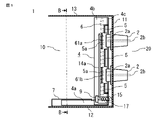
- FIG. 2 is a cross-sectional view showing a side surface of the drawer device for electrical equipment according to Embodiment 1, showing a state in which the electrical equipment is pulled out;
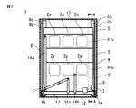
- FIG. 2 is a cross-sectional view showing the front of the drawer device for electrical equipment according to Embodiment 1, showing a state in which the electrical equipment is pulled out;
- FIG. 2 is a cross-sectional view showing a side surface of the drawer device for electrical equipment according to Embodiment 1, showing a state in which the electrical equipment is inserted.
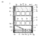
- FIG. 2 is a cross-sectional view showing the front of the drawer device for electrical equipment according to Embodiment 1, showing a state in which the electrical equipment is inserted.
- Embodiment 1. 1 to 4 are diagrams showing the structure of the drawer device for electrical equipment according to the first embodiment. 1 and 2 show the drawer device with the electrical equipment drawn out.
- FIG. 1 is a cross-sectional view showing a side surface of a drawer device for electrical equipment.
- 2 is a front view of FIG. 1.
- FIG. 1 shows the section AA in FIG. 2, and
- FIG. 2 shows the section BB in FIG. 1 and 2, illustration of the electrical equipment that is pulled out is omitted.
- 3 and 4 show the drawing device for electrical equipment in a state in which the electrical equipment is inserted into the metal-enclosed switchgear.
- FIG. 3 is a cross-sectional view showing the side of the drawer device for electric equipment. 4 is a front view of FIG. 3.
- FIG. 3 is a cross-sectional view showing the side of the drawer device for electric equipment. 4
- FIG. 3 shows the cross section CC in FIG. 4, and FIG. 4 shows the cross section DD in FIG.
- the electrical equipment inserted is shown by the dashed-dotted line, and the illustration of the electrical equipment is abbreviate
- FIG. 1 and 2 show the structure of a compartment 10 in which a drawer device for drawable electrical equipment of the metal-enclosed switchgear 1 is arranged.
- a compartment 10 in which the electric equipment 3 that can be pulled out is arranged is partitioned from a high-voltage section 20 by a partition plate 11 made of ground metal. Further, it is composed of a floor plate 12 and a ceiling plate 13 which are ground metals, and a pair of rails 7 for guiding the movement of the drawable electric device 3 in and out (insertion and drawing).
- the electrical equipment 3 is, for example, a circuit breaker, a disconnecting switch, a current transformer, or an instrument transformer.
- the high-voltage charging section 2b is connected, and the connecting section of the electric device 3 and the high-voltage charging section 2b are disconnected when the electric device 3 is pulled out.
- the pull-out device for the electrical equipment 3 has a pair of side plates 4 arranged inside rails 7 that guide the insertion and extraction of the electrical equipment 3.
- a shield plate 5 provided between the side plates 4 and a driving mechanism for driving them. It consists of a device that The side plate 4 having the side plate bottom portion 4a and the side plate support portion 4b has an L-shape when viewed from the side, and the side surface of the side plate bottom portion 4a extending in the loading/unloading direction is guided by the rail 7, so that the electric equipment 3 is supported. It can move in and out.
- the rail 7 for supporting the side plate bottom portion 4a and the rail 7 for taking in and out the electrical equipment 3 are shared, but they may be provided separately.
- a shielding plate 5 is fixed between a pair of side plate support portions 4b erected from the side plate bottom portion 4a.
- the shielding plate 5 may be composed of one sheet or a plurality of sheets, and the number thereof is not limited.
- the shield plate 5 is arranged so as to have an opening 5a corresponding to the connection port 2a of the bushing 2.
- the side plate support 4b of the side plate 4 is provided with an opening/closing plate guide rail 6 that guides the operation of the opening/closing plates 61a and 61b that open/close the opening 5a of the shielding plate 5 in conjunction with the position of the electrical device 3. .
- the side plates 4 are also provided with opening/closing plate links 14a and 14b for driving the opening/closing plates 61a and 61b. It is These opening/closing plate links 14a, 14b and connecting link 17 constitute an opening/closing mechanism for driving the opening/closing plates 61a, 61b.
- the side plate support portion 4b of the side plate 4 has a frame portion 4c on the side of the partition plate 11, and a shielding plate 5 is provided between the pair of frame portions 4c with a predetermined distance therebetween.
- opening/closing plates 61a and 61b are attached movably along the opening/closing plate guide rails 6 provided on the side plate support portion 4b so as to cover the opening 5a without the shielding plate 5. As shown in FIG.
- the opening/closing plates 61a and 61b are positioned to cover the opening 5a of the shielding plate 5 when the electric device 3 shown in FIGS. 1 and 2 is pulled out, and as shown in FIGS. is inserted, the opening/closing plates 61a and 61b are moved to a position overlapping the shielding plate 5.
- a slide link 9 for horizontally moving the side plate 4 along the rail 7 in conjunction with the position of the electric device 3 is arranged at the bottom of the side plate support portion 4b.
- a return spring 15 is provided between the slide link 9 and the partition plate 11 for moving the side plate 4 in accordance with the drawer position of the electrical equipment 3 . As shown in FIG.
- the return spring 15 is configured so that when the electrical equipment 3 is pulled out, the shield plate 5 provided on the side plate 4 and the opening/closing plates 61a and 61b move around the connection port 2a to the high voltage section 20.
- the side plate 4 is moved to the return position so as to be covered.
- the return spring 15 and the slide link 9 form a slide mechanism for moving the side plate 4 in the direction in which the electric device 3 is taken in and out.
- connection port 2a of the bushing 2 is covered with the ground metal shielding plate 5 and the opening/closing plates 61a, 61b to prevent electric shock to the operator. Countermeasures are being taken.
- the opening/closing plate links 14a and 14b are operated in conjunction with the insertion position of the electrical equipment 3.
- the electric device 3 is mounted on a carriage 3a that is movable in the pull-out direction, and moves together with the carriage 3a in the insertion direction of the connection port 2a.
- the pull-out mechanism provided on the electrical equipment 3 or the carriage 3a engages with the opening/closing mechanism of the connecting link 17 and the opening/closing plate links 14a, 14b to move the opening/closing plates 61a, 61b up and down. It moves, and the opening part 5a corresponding to the connection port 2a of the bushing 2 opens.
- the side plate 4 is shielded while compressing the return spring 15 by engaging the slide link 9 that horizontally moves the side plate 4 according to the position of the electric device 3 and the drawer mechanism of the carriage 3a. It is moved along with the plate 5 in the insertion direction of the electric device 3 .
- the shield plate 5 which is a ground metal connected to the side plate 4, is housed between the electric device 3 and the high voltage section 20 with the partition plate 11 interposed therebetween, and the movement is completed. In addition, an insulating distance is ensured between the shielding plate 5 and the high-voltage charging portion 2b.
- the connection port 2a of is covered with the shield plate 5 and the opening/closing plates 61a and 61b.
- the side plate 4 having the side plate bottom portion 4a and the side plate support portion 4b has an L-shaped side surface, and the side surface of the side plate bottom portion 4a is guided by the rails 7 so that the side plate 4 can move smoothly. ing. Since the side plate 4 is supported by the L-shaped side plate bottom portion 4a in this way, the side plate 4 can be supported without further providing a guide rail or the like above the side plate support portion 4b.
- the side plate 4 is not limited to the L-shape, and may have any other shape as long as the side plate 4 can be supported by the side plate bottom portion 4a and the rail 7. FIG.
- the shield plate 5 for preventing electric shock can be moved with a simple structure. As a result, it is possible to obtain a pull-out device for the electric equipment 3 that can protect the operator from touching the high-voltage charging portion 2b when the electric equipment 3 is pulled out during inspection. Further, by supporting the side plate bottom portion 4a with the rail 7, the shielding plate 5 can be prevented from overturning during movement. Further, by dividing the shielding plate 5 and fixing it to the side plate 4, the shielding plate 5 can be made smaller and lighter.
- the opening/closing mechanism of the opening/closing plates 61a and 61b is driven by engaging with the drawer mechanism provided on the carriage 3a of the electrical equipment 3, an extra structure can be omitted in the main body of the electrical equipment 3, and the drawer can be pulled out. Possible standardization of electrical equipment 3 is possible.
- Embodiment 1 the structure in which the connecting link 17 for driving the opening/closing plate links 14a and 14b is provided between the side plates 4 is shown. may be In that case, the same effect can be expected, and the structure provided on the side plate 4 can be simplified. Furthermore, in Embodiment 1, the pair of side plate bottoms 4a are provided inside the pair of rails 7, but the structure may be such that they are provided outside the rails 7, and the side plate bottoms 4a may be provided inside the rails 7 sufficiently. A similar effect can be expected even if the dimensions cannot be obtained.
Landscapes
- Engineering & Computer Science (AREA)
- Power Engineering (AREA)
- Trip Switchboards (AREA)
- Patch Boards (AREA)
- Electrical Discharge Machining, Electrochemical Machining, And Combined Machining (AREA)
- Operating, Guiding And Securing Of Roll- Type Closing Members (AREA)
Priority Applications (6)
| Application Number | Priority Date | Filing Date | Title |
|---|---|---|---|
| JP2023525276A JP7466775B2 (ja) | 2021-06-03 | 2021-06-03 | 電機機器の引出し装置およびスイッチギヤ |
| KR1020237036825A KR102793176B1 (ko) | 2021-06-03 | 2021-06-03 | 전기 기기의 인출 장치 및 스위치 기어 |
| CN202180098479.5A CN117397137A (zh) | 2021-06-03 | 2021-06-03 | 电机设备的引出装置以及开关柜 |
| DE112021007757.0T DE112021007757T5 (de) | 2021-06-03 | 2021-06-03 | Ausladevorrichtung für elektrische Maschine und Schaltanlage |
| PCT/JP2021/021187 WO2022254652A1 (ja) | 2021-06-03 | 2021-06-03 | 電機機器の引出し装置およびスイッチギヤ |
| TW110138644A TWI775645B (zh) | 2021-06-03 | 2021-10-19 | 電機機器的拉出裝置及開關機構 |
Applications Claiming Priority (1)
| Application Number | Priority Date | Filing Date | Title |
|---|---|---|---|
| PCT/JP2021/021187 WO2022254652A1 (ja) | 2021-06-03 | 2021-06-03 | 電機機器の引出し装置およびスイッチギヤ |
Publications (1)
| Publication Number | Publication Date |
|---|---|
| WO2022254652A1 true WO2022254652A1 (ja) | 2022-12-08 |
Family
ID=83807422
Family Applications (1)
| Application Number | Title | Priority Date | Filing Date |
|---|---|---|---|
| PCT/JP2021/021187 Ceased WO2022254652A1 (ja) | 2021-06-03 | 2021-06-03 | 電機機器の引出し装置およびスイッチギヤ |
Country Status (6)
| Country | Link |
|---|---|
| JP (1) | JP7466775B2 (enExample) |
| KR (1) | KR102793176B1 (enExample) |
| CN (1) | CN117397137A (enExample) |
| DE (1) | DE112021007757T5 (enExample) |
| TW (1) | TWI775645B (enExample) |
| WO (1) | WO2022254652A1 (enExample) |
Citations (4)
| Publication number | Priority date | Publication date | Assignee | Title |
|---|---|---|---|---|
| JPS5143844U (enExample) * | 1974-09-30 | 1976-03-31 | ||
| JP2002335610A (ja) * | 2001-05-08 | 2002-11-22 | Mitsubishi Electric Corp | 開閉器のシャッタ機構 |
| JP2009017628A (ja) * | 2007-07-02 | 2009-01-22 | Fuji Electric Systems Co Ltd | 配電盤のシャッタ装置 |
| JP2013153565A (ja) * | 2012-01-24 | 2013-08-08 | Chugoku Electric Power Co Inc:The | 電気盤 |
Family Cites Families (6)
| Publication number | Priority date | Publication date | Assignee | Title |
|---|---|---|---|---|
| US4090230A (en) * | 1977-02-10 | 1978-05-16 | Square D Company | High voltage motor starter enclosure |
| US7140702B2 (en) * | 2001-12-21 | 2006-11-28 | Square D Company | Medium voltage motor control center arc resistant enclosure |
| JP2009171774A (ja) * | 2008-01-17 | 2009-07-30 | Chugoku Electric Power Co Inc:The | スイッチギヤの遮蔽装置 |
| CN109462166B (zh) * | 2018-11-09 | 2020-06-26 | 国网安徽省电力有限公司宿州供电公司 | 一种高压开关柜手车开关导轨 |
| US20200391499A1 (en) * | 2019-06-13 | 2020-12-17 | Illinois Tool Works Inc. | Automated printer robotic arm |
| CN211018005U (zh) * | 2019-10-31 | 2020-07-14 | 甘肃西电电气集团有限公司 | 一种新型中置式高压开关柜 |
-
2021
- 2021-06-03 DE DE112021007757.0T patent/DE112021007757T5/de active Pending
- 2021-06-03 CN CN202180098479.5A patent/CN117397137A/zh active Pending
- 2021-06-03 JP JP2023525276A patent/JP7466775B2/ja active Active
- 2021-06-03 WO PCT/JP2021/021187 patent/WO2022254652A1/ja not_active Ceased
- 2021-06-03 KR KR1020237036825A patent/KR102793176B1/ko active Active
- 2021-10-19 TW TW110138644A patent/TWI775645B/zh active
Patent Citations (4)
| Publication number | Priority date | Publication date | Assignee | Title |
|---|---|---|---|---|
| JPS5143844U (enExample) * | 1974-09-30 | 1976-03-31 | ||
| JP2002335610A (ja) * | 2001-05-08 | 2002-11-22 | Mitsubishi Electric Corp | 開閉器のシャッタ機構 |
| JP2009017628A (ja) * | 2007-07-02 | 2009-01-22 | Fuji Electric Systems Co Ltd | 配電盤のシャッタ装置 |
| JP2013153565A (ja) * | 2012-01-24 | 2013-08-08 | Chugoku Electric Power Co Inc:The | 電気盤 |
Also Published As
| Publication number | Publication date |
|---|---|
| KR20230162047A (ko) | 2023-11-28 |
| CN117397137A (zh) | 2024-01-12 |
| KR102793176B1 (ko) | 2025-04-08 |
| DE112021007757T5 (de) | 2024-04-11 |
| TW202249372A (zh) | 2022-12-16 |
| TWI775645B (zh) | 2022-08-21 |
| JP7466775B2 (ja) | 2024-04-12 |
| JPWO2022254652A1 (enExample) | 2022-12-08 |
Similar Documents
| Publication | Publication Date | Title |
|---|---|---|
| TWI385884B (zh) | 開關設備的接地裝置 | |
| US10587098B2 (en) | Medium voltage switchgear enclosure | |
| KR101633567B1 (ko) | 스위치 기어 | |
| US8727456B1 (en) | Draw out control compartment | |
| RU2592073C2 (ru) | Гибкая крышка для контактов вставного или выдвижного блока | |
| EP2346064A1 (en) | Electrical switching apparatus and mounting assembly therefor | |
| JP2011078273A (ja) | 配電盤の作業台車および配電盤 | |
| JP5150589B2 (ja) | スイッチギヤ | |
| CN111697478B (zh) | 配电箱的电弧排出系统 | |
| WO2022254652A1 (ja) | 電機機器の引出し装置およびスイッチギヤ | |
| JP4870649B2 (ja) | 配電盤 | |
| JP5538651B2 (ja) | 配電盤のシャッタ装置 | |
| CN219394085U (zh) | 一种船用中压配电柜 | |
| WO2022178966A1 (en) | Switchgear system having contact arm assembly for switchgear circuit breaker | |
| JP2011097768A (ja) | スイッチギヤ | |
| CN103975493B (zh) | 开关装置 | |
| KR20250084169A (ko) | 배전반 | |
| KR102716933B1 (ko) | 서랍식 기기 패널을 갖는 배전반 | |
| JP2025182339A (ja) | スイッチギヤ | |
| JP2020065336A (ja) | 金属閉鎖形配電盤 | |
| JPH0564325A (ja) | 閉鎖形配電盤 | |
| KR20200145382A (ko) | 배전반의 아크 배출 시스템 | |
| JPS59198806A (ja) | 配電盤の台車形接地装置 | |
| HK1209238A1 (en) | Vacuum circuit breaker | |
| HK1209238B (en) | Vacuum circuit breaker |
Legal Events
| Date | Code | Title | Description |
|---|---|---|---|
| 121 | Ep: the epo has been informed by wipo that ep was designated in this application |
Ref document number: 21944153 Country of ref document: EP Kind code of ref document: A1 |
|
| WWE | Wipo information: entry into national phase |
Ref document number: 2023525276 Country of ref document: JP |
|
| ENP | Entry into the national phase |
Ref document number: 20237036825 Country of ref document: KR Kind code of ref document: A |
|
| WWE | Wipo information: entry into national phase |
Ref document number: 1020237036825 Country of ref document: KR |
|
| WWE | Wipo information: entry into national phase |
Ref document number: 202180098479.5 Country of ref document: CN |
|
| WWE | Wipo information: entry into national phase |
Ref document number: 112021007757 Country of ref document: DE |
|
| 122 | Ep: pct application non-entry in european phase |
Ref document number: 21944153 Country of ref document: EP Kind code of ref document: A1 |