WO2022250026A1 - Dispositif d'aiguillage et système de transport sur rails à guidage central - Google Patents
Dispositif d'aiguillage et système de transport sur rails à guidage central Download PDFInfo
- Publication number
- WO2022250026A1 WO2022250026A1 PCT/JP2022/021164 JP2022021164W WO2022250026A1 WO 2022250026 A1 WO2022250026 A1 WO 2022250026A1 JP 2022021164 W JP2022021164 W JP 2022021164W WO 2022250026 A1 WO2022250026 A1 WO 2022250026A1
- Authority
- WO
- WIPO (PCT)
- Prior art keywords
- branch
- movable guide
- main line
- guide
- movable
- Prior art date
Links
- 230000000694 effects Effects 0.000 description 3
- 229920001971 elastomer Polymers 0.000 description 3
- 239000000203 mixture Substances 0.000 description 3
- 229910000831 Steel Inorganic materials 0.000 description 2
- 238000012423 maintenance Methods 0.000 description 2
- 238000005096 rolling process Methods 0.000 description 2
- 239000010959 steel Substances 0.000 description 2
- 229920006311 Urethane elastomer Polymers 0.000 description 1
- 230000015572 biosynthetic process Effects 0.000 description 1
- 230000005611 electricity Effects 0.000 description 1
- 230000014509 gene expression Effects 0.000 description 1
- 230000001771 impaired effect Effects 0.000 description 1
- 230000002093 peripheral effect Effects 0.000 description 1
- 238000007788 roughening Methods 0.000 description 1
Images


Classifications
-
- E—FIXED CONSTRUCTIONS
- E01—CONSTRUCTION OF ROADS, RAILWAYS, OR BRIDGES
- E01B—PERMANENT WAY; PERMANENT-WAY TOOLS; MACHINES FOR MAKING RAILWAYS OF ALL KINDS
- E01B25/00—Tracks for special kinds of railways
- E01B25/28—Rail tracks for guiding vehicles when running on road or similar surface
-
- B—PERFORMING OPERATIONS; TRANSPORTING
- B61—RAILWAYS
- B61B—RAILWAY SYSTEMS; EQUIPMENT THEREFOR NOT OTHERWISE PROVIDED FOR
- B61B13/00—Other railway systems
Definitions
- track-based transportation systems that run on tracks with running wheels fitted with rubber tires are known.
- track-based transportation systems there is a center-guided track-based transportation system in which a guide wheel is arranged in the center of the vehicle.
- a bifurcation area is formed in which the track is divided into two.
- a branching device is arranged in this branching area for moving a guide for guiding the vehicle.
- a branching device applied to such a center guidance type track-based transportation system for example, there is a device disclosed in Patent Document 1 below.
- Patent Document 1 a branch equipped with a main line movable rail and a branch line movable rail that rotates between a guide position and a retracted position with respect to a fixed rail that is a guide arranged in the center of the width direction of the running path.
- a device is described.
- the main line movable rail is arranged at the guide position, and the branch line movable rail is arranged at the retracted position, so that the vehicle goes straight and is guided to the main lane.
- the main line movable rail is arranged at the retracted position and the branch line movable rail is arranged at the guidance position, so that the vehicle is guided onto the branch line traveling path branched from the main line traveling path.
- the main line movable rail and branch line movable rail which are movable guides, may become extremely long.
- a large space is required in the branch area in order to move the movable guide so as not to interfere with the running of the vehicle.
- the present disclosure provides a branching device and a center guidance type track-based transportation system that can reduce the space of the branching area regardless of the shape of the branching area.
- a branching device is a branching device arranged in a branching area between a main track and a branch track, the branching device being capable of guiding a vehicle from the first main track to the second main track;
- a first main line movable guide and a second main line movable guide that are movable between a main line evacuation position in which the vehicle cannot be guided from the main line track to the second main line track, and a second main line movable guide from the first main line track to the branch track.
- a first branch movable guide and a second branch movable guide that are movable between a branch guide position where the vehicle can be guided and a branch retreat position where the vehicle cannot be guided from the first main track to the branch track.
- a movable device for moving the first main line movable guide, the second main line movable guide, the first branch movable guide, and the second branch movable guide.
- the center-guided track-based traffic system includes: the branching device; a main track extending in a first direction and having a running surface with which the running wheels of the vehicle can contact;
- the main track having a main guide arranged on a first imaginary center line located in the center of the direction and guiding the vehicle, and a second direction different from the first direction so as to branch from the main track a branched track that extends and has the running surface; and a branched guide that is arranged on a second imaginary center line positioned at the center of the branched track in the width direction and guides the vehicle.
- the space of the branching area can be reduced regardless of the shape of the branching area.
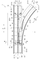
- FIG. 1 is a plan view showing the configuration of a center guidance type track-based transportation system according to a first embodiment
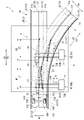
- FIG. FIG. 2 is a plan view showing a state in which a vehicle is caused to run on a main track in the track-based transportation system of the central guidance type according to the present embodiment
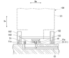
- 3 is a cross-sectional view taken along line III-III of FIG. 2
- FIG. FIG. 2 is a plan view showing a state when a vehicle is caused to run on a branched track in the central guidance type track-based transportation system according to the present embodiment
- 5 is a cross-sectional view taken along line VV of FIG. 4
- FIG. FIG. 10 is a plan view showing the configuration of a central guide-type track-based transportation system according to a second embodiment
- FIG. 11 is a plan view showing the configuration of a central guide-type track-based transportation system according to a third embodiment
- a central guidance type track-based transportation system 1 of the embodiment according to the present disclosure is a system in which a central guidance type vehicle 100 travels along a track 10 .
- a vehicle 100 traveling on a track 10 in the embodiment of the present disclosure is a vehicle 100 of a guide rail type new transportation system.
- the vehicles 100 are operated with one or more vehicles as one formation.
- the vehicles 100 are connected to each other by a connecting device (not shown).
- Each vehicle 100 includes a vehicle body 101 , running wheels 102 , guide wheels 103 and current collectors 104 .
- a plurality of running wheels 102 are arranged under the vehicle body 101 .
- the running wheels 102 are made of rubber tires and driven to rotate by an electric motor (not shown).
- the vehicle 100 travels along a guide 12, which will be described later, on the travel path 11 of the track 10 while the running wheels 102 are steered.
- a plurality of guide wheels 103 are arranged in the lower part of the vehicle body 101 .
- the guide wheel 103 has an outer peripheral portion made of an elastic member such as urethane rubber.
- a pair of guide wheels 103 of the present embodiment are arranged at the center of the vehicle body 101 in the vehicle width direction so as to sandwich a rail-shaped guide 12, which will be described later.
- the guide wheel 103 is arranged at the lower center of the vehicle body 101 so as to be sandwiched between the pair of running wheels 102 in the vehicle width direction.
- Two pairs of guide wheels 103 are arranged on one vehicle body 101 so as to be separated from each other in the front-rear direction.
- the current collector 104 supplies electric power to the electric motor that rotates the running wheels 102 by coming into contact with the electric wire 13, which will be described later.
- a pair of current collectors 104 of the present embodiment are arranged on the outer side of the vehicle body 101 in the vehicle width direction.
- two sets of current collectors 104 are arranged on one vehicle body 101 so as to be separated from each other in the front-rear direction.
- a guide 12 for guiding the vehicle 100 is arranged in the center of the travel path 11 on which the vehicle 100 travels.
- the center guidance type track-based transportation system 1 of the first embodiment mainly includes a track 10 and a branching device 4 .
- a vehicle 100 can run on the track 10 .
- the track 10 extends along a predetermined route.
- a track 10 is formed with a track 11 on which the vehicle 100 runs.
- the running path 11 extends in the extension direction De.
- the extension direction De is a direction that intersects (perpendicularly in this embodiment) the vertical direction Dv (see FIG. 3), and is the direction in which the track 10 extends.
- a running surface 11 a is formed on each running path 11 .
- the running surface 11 a is a flat surface that can be contacted while the running wheels 102 roll when the vehicle 100 runs on the running path 11 .
- the running surfaces 11a are spaced apart in a width direction Dw that intersects (perpendicularly in this embodiment) the extension direction De and the vertical direction Dv so as to correspond to the positions of the pair of running wheels 102 of the vehicle 100. form a pair.
- the running surface 11a is entirely flat and formed so that running wheels 102 on which rubber tires of the vehicle 100 are mounted can roll. As the running wheels 102 roll on the running surface 11 a, the vehicle 100 runs on the running path 11 .
- the running surface 11a of the present embodiment is not actually formed apart in the width direction Dw, but is integrally formed as part of the flat upper surface of the running path 11 across the width direction Dw and extending left and right. ing. Therefore, the running surface 11a in the present embodiment is a region of the upper surface facing upward in the vertical direction Dv on the running path 11, with which the running wheels 102 are assumed to come into contact when the vehicle 100 runs on the running path 11. is. Further, the surface of the running surface 11a is subjected to grooving, roughening, or the like to such an extent that the flatness is not impaired. As a result, the surface of the running surface 11a is a surface that secures a coefficient of friction with the tire tread surface and prevents slippage during rainfall or the like.
- the track 10 of this embodiment further includes a guide 12 that guides the vehicle 100 and a contact line 13 that supplies electricity to the vehicle 100 .
- the guide wheels 103 can come into contact with the guides 12 and guide the traveling direction of the vehicle 100 so that it moves along the travel path 11 .
- the guide 12 extends in the extension direction De over the entire extension of the track 10 .
- the guide 12 is a rail-shaped member made of H-shaped steel or I-shaped steel.
- the guide 12 is arranged at the center in the width direction Dw with respect to the surface (upper surface of the travel path 11) along the travel surface 11a.
- the guide 12 extends in the extending direction De at the same height from the upper surface of the travel path 11 . That is, the guide 12 is arranged in a state of protruding upward in the vertical direction Dv with respect to the running surface 11a.
- the train line 13 supplies electric power to the vehicle 100 by contacting the current collector 104 of the vehicle 100 .
- the train line 13 extends in the extending direction De.
- the contact line 13 is arranged outside in the width direction Dw with respect to the running surface 11a.
- the contact line 13 extends in the extending direction De at the same height from the upper surface of the travel path 11 at a position higher than the guide 12 in the vertical direction Dv.
- two contact lines 13 are arranged in the case of a DC power supply, and three contact lines 13 in the case of an AC power supply.
- the track 10 of the present embodiment includes a main track 2 and branch tracks 3 branched from the main track 2 .
- the direction in which the main track 2 extends is called a first direction D1
- the direction in which the branch tracks 3 extend is called a second direction D2.
- the second direction D2 is a direction crossing the first direction D1 on a virtual plane parallel to the running surface 11a.
- the width direction Dw is a direction orthogonal to the extension direction De, the main track 2 and the branch track 3 have different directions.
- branch area A the area where the main track 2 starts to branch to the branch track 3 will be referred to as a branch area A.
- branch area A part of the main track 2 and part of the branch track 3 overlap.
- a branching device 4 is arranged in the branching area A.
- branch area A of the present embodiment only one branch track 3 extending in a different direction is connected to the main track 2 .
- the front side of the traveling direction of the vehicle 100 traveling on the main track 2 with respect to the branch area A (the side where the vehicle 100 is arranged in FIG. 1) is referred to as the first side in the first direction D1.
- the forward side of the vehicle 100 traveling on the main track 2 with respect to the branch area A (the side on which the vehicle 100 is not arranged in FIG. 1) is referred to as the second side in the first direction D1.
- the main track 2 includes a first main track 2A arranged on the first side in the first direction D1 with respect to the branch area A, and a first main track 2A on the opposite side of the branch area A from the first main track 2A in the first direction D1.
- the front side of the traveling direction of the vehicle 100 toward the branched track 3 from the first main track 2A with respect to the branch area A (the side where the first main track 2A is arranged with respect to the branched track 3 in FIG. 1). It is called the first side of the second direction D2.
- the forward side of the traveling direction of the vehicle 100 toward the branched track 3 from the first main track 2A with respect to the branch area A (the side where the branched track 3 is arranged with respect to the first main track 2A in FIG. 1) is referred to as the second It will be referred to as the second side in direction D2.
- the main track 2 has a main track 21 that is part of the track 11 , a main track guide 22 that is part of the guide 12 , and a main contact line 23 that is part of the contact line 13 . Therefore, the first main track 2A and the second main track 2B have a main track 21, a main guide 22, and a main contact line 23, respectively.
- the main road 21 extends in the first direction D1 so that the vehicle 100 can run.
- the main road 21 has a running surface 11a on which the running wheels 102 of the vehicle 100 come into contact while rolling.
- the upper surface of the main travel path 21 is formed so as to be connected in the width direction Dw, and is integrally formed over the left and right. Therefore, part of the upper surface of the main track 21 forms the running surface 11a.
- the main line guide 22 guides the traveling direction of the vehicle 100 so as to move along the main line travel path 21 by contact with the guide wheels 103 .
- the main line guide 22 is arranged on the first imaginary center line O1 positioned at the center of the main line traveling path 21 in the width direction Dw.
- the first imaginary center line O1 is an imaginary line that indicates the center of the width direction Dw between the running surfaces 11a of the main road 21 on the main road 21, and extends in the first direction D1. Therefore, the first imaginary center line O1 extends so as not to overlap the running surface 11a of the main running path 21 .
- the main train line 23 extends in the first direction D1.
- the main contact line 23 is arranged outside the main track 21 in the width direction Dw.
- the main contact lines 23 are arranged on the left and right sides in the traveling direction of the vehicle 100 when the vehicle 100 advances from the first main track 2A to the second main track 2B.
- the main contact line 23 arranged on the right side of the vehicle 100 (the side where the branch track 3 is arranged) is in the branch area A. It is arranged on the first side in the first direction D1 and is not arranged on the second side.
- the main contact line 23 arranged on the left side of the vehicle 100 (the side where the branch track 3 is not arranged) is also in the branch area A. It extends in the first direction D1 without a break.
- the main contact line 23 extends in the extension direction De at the same height from the upper surface of the main line travel path 21 at a position higher than the main line guide 22 in the vertical direction Dv.
- the branch track 3 has a branch track 31 that is part of the track 11 , a branch guide 32 that is part of the guide 12 , and a branch contact line 33 that is part of the contact line 13 .
- the branch road 31 extends in the second direction D2 from the middle of the main road 21 so as to branch off from the main road 21 .
- the branch road 31 is connected to the main road 21 while curving in the branch area A.
- the branch road 31 has a running surface 11a on which the running wheels 102 of the vehicle 100 come into contact while rolling.
- the upper surface of the branched travel path 31 is formed so as to be connected in the width direction Dw, and is integrally formed over the left and right. Therefore, part of the upper surface of the branched travel path 31 forms the travel surface 11a.
- the branch guide 32 guides the traveling direction of the vehicle 100 so as to move along the branch travel path 31 by contact with the guide wheel 103 .
- the branch guide 32 is arranged on the second imaginary center line O2 positioned at the center of the branch travel path 31 in the width direction Dw.
- the second imaginary center line O2 is an imaginary line that indicates the center of the width direction Dw between the running surfaces 11a of the branching path 31 and extends in the second direction D2. Therefore, the second imaginary center line O2 extends so as not to overlap the running surface 11a of the branch running path 31 .
- the branch guide 32 is a rail-shaped member formed to have the same cross-sectional shape as the main line guide 22 .
- the branch train line 33 extends in the second direction D2.
- the branched contact line 33 is arranged outside the branched travel path 31 in the width direction Dw.
- the branch contact lines 33 are arranged on the left and right in the traveling direction of the vehicle 100 when the vehicle 100 advances from the first main track 2A to the branch track 3 .
- the branch contact line 33 arranged on the right side of the vehicle 100 (the side where the second main track 2B is not arranged) is in the branch area A. It is connected to the main train line 23 without interruption.
- the branch contact line 33 is not arranged on the left side of the vehicle 100 (the side where the second main track 2B is arranged).
- the branch trolley line 33 extends in the extension direction De at the same height from the upper surface of the branch travel path 31 at a position higher than the branch guide 32 in the vertical direction Dv.
- the branching device 4 is a device for switching the track 10 on which the vehicle 100 travels between the main track 2 and the branch track 3 . Therefore, the branching device 4 guides the vehicle 100 traveling on the first main track 2A to the second main track 2B or the branch track 3, for example.
- a state in which the branching device 4 is switched so as to guide the vehicle 100 traveling on the first main track 2A to the second main track 2B is referred to as a first state.
- a state in which the branching device 4 is switched so as to guide the vehicle 100 traveling on the first main track 2A to the branched track 3 is referred to as a second state.
- the branching device 4 of this embodiment includes a first main line movable guide 41, a second main line movable guide 42, a main line fixed guide 43, a first branch movable guide 51, a second branch movable guide 52, and a branch fixed guide. 53 and a movable device 6 .
- the first main line movable guide 41, the second main line movable guide 42, the main line fixed guide 43, the first branch movable guide 51, the second branch movable guide 52, and the branch fixed guide 53 are part of the guide 12 in the branch area A. be.
- the first main line movable guide 41 together with the second main line movable guide 42, guides the vehicle 100 traveling on the main track 2 in the branch area A.
- the first main line movable guide 41 together with the second main line movable guide 42, moves between a main line guiding position capable of guiding the vehicle 100 from the first main line track 2A to the second main line track 2B, and from the first main line track 2A to the second main line track 2B.
- the vehicle 100 can be moved between the main line evacuation position and the main line evacuation position where the vehicle 100 cannot be guided.
- the main track guidance position is a position where the guide wheels 103 of the passing vehicle 100 can come into contact and guides the vehicle 100 to the second main track 2B.
- the main lane evacuation position is a position where the guide wheels 103 of the passing vehicle 100 cannot contact.
- the first main line movable guide 41 is arranged in the branch area A. As shown in FIG.
- the first main line movable guide 41 is arranged at a position closer to the first main line track 2A than the second main line movable guide 42 in the first direction D1 when viewed from above in the vertical direction Dv.
- the first main line movable guide 41 is a rail-shaped member formed to have the same cross-sectional shape as the main line guide 22 .
- the first main line movable guide 41 is rotatably supported with respect to the running surface 11a.
- the first main line movable guide 41 of the present embodiment is rotatable around a rotation shaft arranged at one end, which is the base end.
- one end (first end) of the first main line movable guide 41 is the end on the first side in the first direction D1.
- the other end (second end) of the first main line movable guide 41 is the end opposite to the one end, and is the end on the second side in the first direction D1.
- One end of the first main line movable guide 41 is arranged at a position overlapping the first imaginary center line O1 when viewed from above in the vertical direction Dv.
- the first main line movable guide 41 is rotatable about one end on the first imaginary center line O1 so as to move the other end between the main line guiding position and the main line retracted position. It is said that In this embodiment, the other end, which is the tip of the first main line movable guide 41, moves away from the branch track 3 with respect to the first imaginary center line O1 when moving from the main line guide position to the main line withdrawal position. move around. As shown in FIGS. 2 and 3, at the main line guiding position, the other end of the first main line movable guide 41 is arranged on the first imaginary center line O1.
- the first main line movable guide 41 extends straight on the first imaginary center line O1 when viewed in the vertical direction Dv.
- the other end of the first main line movable guide 41 is in contact with the end of the main line guide 22 of the first main line track 2A in the width direction Dw. 4 and 5, at the main line retracted position, the other end of the first main line movable guide 41 is located at a position off the first virtual center line O1 and on the running surface 11a of the branch running path 31.
- the other end of the first mainline movable guide 41 is arranged at a position away from the running surface 11a of the mainline running path 21 at the mainline retracted position.
- the first main line movable guide 41 is inclined with respect to the first imaginary center line O1 when viewed from the vertical direction Dv.
- the second main line movable guide 42 is arranged in the branch area A at a position separated from the first main line movable guide 41 .
- the second main line movable guide 42 is arranged at a position closer to the second main line track 2B than the first main line movable guide 41 in the first direction D1 when viewed from above in the vertical direction Dv.
- the second main line movable guide 42 is a rail-shaped member formed to have the same cross-sectional shape as the main line guide 22 .
- the second main line movable guide 42 is rotatably supported with respect to the running surface 11a.
- the second main line movable guide 42 of the present embodiment is rotatable around a rotation shaft arranged at one end, which is the base end.
- one end (first end) of the second main line movable guide 42 is the end on the first side in the first direction D1.
- the other end (second end) of the second main line movable guide 42 is the end opposite to the one end, and is the end on the second side in the first direction D1.
- One end of the second main line movable guide 42 is arranged at a position overlapping the first imaginary center line O1 when viewed from above in the vertical direction Dv.
- One end of the second main line movable guide 42 is arranged at a position adjacent to the end of the main line guide 22 of the second main line track 2B in the first direction D1 when viewed from above in the vertical direction Dv. . Therefore, the second main line movable guide 42 is rotatable about one end on the first imaginary center line O1 so as to move the other end between the main line guiding position and the main line retracted position. It is said that In this embodiment, the other end, which is the tip of the second main line movable guide 42, moves away from the branch track 3 with respect to the first imaginary center line O1 when moving from the main line guide position to the main line retracted position. move around. As shown in FIG.
- the other end of the second main line movable guide 42 is arranged on the first imaginary center line O1.
- the second main line movable guide 42 extends straight on the first imaginary center line O1 when viewed from the vertical direction Dv.
- the other end of the second main line movable guide 42 is off the first imaginary center line O1 and on the running surface 11a of the branch running path 31. placed in position.
- the other end of the second main line movable guide 42 is arranged at a position separated from the running surface 11a of the branch running path 31 at the main line retracted position. Accordingly, at the main line retracted position, the second main line movable guide 42 is inclined with respect to the first imaginary center line O1 when viewed from the vertical direction Dv.
- the main line fixed guide 43 guides the vehicle 100 traveling on the main line track 2 in the branch area A together with the first main line movable guide 41 and the second main line movable guide 42 .
- the main line fixed guide 43 is arranged in the branch area A in a non-movable state. That is, the main line fixed guide 43 is fixed to the main line travel path 21 .
- the main line fixed guide 43 is arranged between the first main line movable guide 41 and the second main line movable guide 42 in the first direction D1.
- the main line fixed guide 43 is arranged at a position off the running surface 11 a of the branch running path 31 .
- the main line fixed guide 43 is formed in a straight line so as to extend on the first imaginary center line O1.
- the main line fixed guide 43 is a rail-shaped member formed to have the same cross-sectional shape as the main line guide 22 .
- the main line fixed guide 43 is shorter than the first main line movable guide 41 and the second main line movable guide 42 .
- the main line fixed guide 43 can contact at least one of the first main line movable guide 41 and the second main line movable guide 42 in a state where the first main line movable guide 41 and the second main line movable guide 42 are positioned at the main line guiding position. ing.
- One end of the main line fixed guide 43 of the present embodiment contacts the other end of the second main line movable guide 42 in the width direction Dw while the second main line movable guide 42 is positioned at the main line guiding position. are placed in The other end of the main line fixed guide 43 is adjacent to one end of the first main line movable guide 41 in the first direction D1.
- the first branch movable guide 51 guides the vehicle 100 traveling on the branch track 3 in the branch area A together with the second branch movable guide 52 .
- the first branch movable guide 51, together with the second branch movable guide 52, has a branch guide position capable of guiding the vehicle 100 from the first main track 2A to the branch track 3, and the vehicle 100 from the first main track 2A to the branch track 3. It is movable between a branch retraction position where guidance is not possible.
- the branch guidance position is a position where the guide wheel 103 of the passing vehicle 100 can contact and guides the vehicle 100 to the branch track 3 .
- the branch retreat position is a position in which contact with the guide wheels 103 of the passing vehicle 100 is impossible.
- the first branch movable guide 51 is arranged in the branch area A.
- the first branch movable guide 51 is arranged at a position closer to the first main track 2A than the second branch movable guide 52 in the second direction D2 when viewed from above in the vertical direction Dv.
- the first branch movable guide 51 is a rail-shaped member formed to have the same cross-sectional shape as the main line guide 22 .
- the first branch movable guide 51 is rotatably supported with respect to the running surface 11a.
- the first branch movable guide 51 of the present embodiment is rotatable around a rotating shaft arranged at one end, which is the proximal end.
- one end (first end) of the first branch movable guide 51 is the end on the first side in the second direction D2.
- the other end (second end) of the first branch movable guide 51 is the end opposite to the one end, and is the end on the second side in the second direction D2.
- One end of the first branch movable guide 51 is arranged at a position overlapping the second imaginary center line O2 when viewed from above in the vertical direction Dv.
- one end of the first branch movable guide 51 is positioned off both the running surface 11a of the main running path 21 and the running surface 11a of the branch running path 31 when viewed from above in the vertical direction Dv. are placed in The first branch movable guide 51 is rotatable about one end on the second imaginary center line O2 so as to move the other end between the branch guide position and the branch retracted position. ing.
- the other end which is the tip of the first branch movable guide 51, moves counterclockwise away from the first imaginary center line O1 when moving from the branch guide position to the branch retracted position.
- the other end of the first branch movable guide 51 is arranged on the first imaginary center line O1 and the second imaginary center line O2.
- the first branch movable guide 51 is curved and extended on the second imaginary center line O2 when viewed in the vertical direction Dv.
- the other end of the first branch movable guide 51 is in contact with the end of the main line guide 22 of the first main line track 2A in the width direction Dw. Further, as shown in FIGS.
- the other end of the first branch movable guide 51 is arranged at a position deviated from the first imaginary center line O1 and the second imaginary center line O2. be.
- the other end of the first branch movable guide 51 is arranged at a position separated from the running surface 11a of the main running path 21 and the running surface 11a of the branch running path 31 at the branch retracted position. .
- the first branch movable guide 51 is inclined with respect to the second imaginary center line O2 when viewed from the vertical direction Dv.
- the second branch movable guide 52 is arranged in the branch area A at a position away from the first branch movable guide 51. As shown in FIG. The second movable branch guide 52 is arranged at a position closer to the branch track 3 than the first movable branch guide 51 in the second direction D2 when viewed from above in the vertical direction Dv.
- the second branch movable guide 52 is a rail-shaped member formed to have the same cross-sectional shape as the main line guide 22 .
- the second branch movable guide 52 is rotatably supported with respect to the running surface 11a.
- the second movable branch guide 52 of the present embodiment is rotatable around a rotation shaft arranged at one end, which is the proximal end, similarly to the first movable branch guide 51.
- one end (first end) of the second branch movable guide 52 is the end on the first side in the second direction D2.
- the other end (second end) of the second branch movable guide 52 is the end opposite to the one end, and is the end on the second side in the second direction D2.
- One end of the second branch movable guide 52 is arranged at a position overlapping the second imaginary center line O2 when viewed from above in the vertical direction Dv.
- One end of the second branch movable guide 52 is arranged at a position adjacent to the end of the branch guide 32 of the branch track 3 in the second direction D2 when viewed from above in the vertical direction Dv. Therefore, the second branch movable guide 52 is rotatable about one end on the second imaginary center line O2 so as to move the other end between the branch guide position and the branch retracted position. It is said that In this embodiment, the other end of the second branch movable guide 52 moves counterclockwise relative to the second imaginary center line O2 so as to move away from the first imaginary center line O1 when moving from the branch guide position to the retracted position. move around. As shown in FIG.
- the other end of the second branch movable guide 52 is arranged on the second imaginary center line O2.
- the second branch movable guide 52 is extended on the second imaginary center line O2 when viewed from the vertical direction Dv.
- the other end of the second branch movable guide 52 is out of the second imaginary center line O2 and out of the running surface 11a of the branch running path 31. placed in position.
- the other end which is the tip of the second branch movable guide 52, is arranged at a position deviated from the running surface 11a of the main track 21 at the branch retracted position.
- the second branch movable guide 52 is inclined with respect to the second imaginary center line O2 when viewed from the vertical direction Dv.
- the branch fixed guide 53 guides the vehicle 100 traveling on the branch track 3 in the branch area A together with the first branch movable guide 51 and the second branch movable guide 52 .
- the branch fixed guide 53 is arranged in the branch area A in a non-movable state.
- the branch fixed guide 53 of this embodiment is fixed to the branch traveling path 31 .
- the branch fixed guide 53 is arranged between the first branch movable guide 51 and the second branch movable guide 52 in the second direction D2.
- the branch fixed guide 53 is arranged at a position separated from the running surface 11 a of the main track 21 .
- the branch fixed guide 53 is curved to extend along the second imaginary center line O2.
- the branch fixed guide 53 is a rail-shaped member formed to have the same cross-sectional shape as the main line guide 22 .
- the branch fixed guide 53 is shorter than the first branch movable guide 51 and the second branch movable guide 52 .
- the branch fixed guide 53 can contact at least one of the first branch movable guide 51 and the second branch movable guide 52 in a state where the first branch movable guide 51 and the second branch movable guide 52 are positioned at the branch guide position. ing.
- One end of the branch fixed guide 53 of the present embodiment contacts the other end of the second branch movable guide 52 in the width direction Dw while the second branch movable guide 52 is positioned at the branch line guide position. placed in position.
- the other end of the branch fixed guide 53 is adjacent to one end of the first branch movable guide 51 in the second direction D2.
- the movable device 6 moves the first main line movable guide 41, the second main line movable guide 42, the first branch movable guide 51, and the second branch movable guide 52.
- the movable device 6 moves the first main line movable guide 41 and the second main line movable guide 42 between the main line guide position and the main line retracted position.
- the movable device 6 moves the first branch movable guide 51 and the second branch movable guide 52 between the branch guide position and the branch retracted position.
- the movable device 6 can temporarily fix the positions of the first main line movable guide 41 and the second main line movable guide 42 at the main line guiding position and the main line retracted position, respectively.
- the movable device 6 can temporarily fix the positions of the first branch movable guide 51 and the second branch movable guide 52 at each of the branch guide position and the branch retreat position.
- the movable device 6 of this embodiment moves the first main line movable guide 41, the second main line movable guide 42, the first branch movable guide 51, and the second branch movable guide 52 at the same time.
- the movable device 6 simultaneously moves the first main line movable guide 41 and the second main line movable guide 42 from the main line retracted position to the main line guiding position, and moves the first branch movable guide 51 and the second main line movable guide 51 and The bifurcated movable guide 52 is simultaneously moved from the branch guide position to the branch retracted position.
- the movable device 6 simultaneously moves the first main line movable guide 41 and the second main line movable guide 42 from the main line guiding position to the main line retracting position, The guide 52 is simultaneously moved from the branch retracted position to the branch guide position.
- the movable device 6 of the present embodiment has a lever body portion 60 , a first rod 61 , a second rod 62 and a lever drive portion 7 .
- the lever main body 60 moves the first rod 61 and the second rod 62 simultaneously by rotating around one end.
- the lever main body 60 is a rod-shaped member extending in the first direction D1.
- the lever main body 60 of the present embodiment is arranged outside the main track 2 opposite to the position where the branch track 3 extends in the width direction Dw.
- the lever main body 60 extends parallel to the main line guide 22 .
- One end of the lever main body 60 is rotatably supported with respect to the main track 2 . Therefore, the lever main body 60 is supported so that the leading end can move around its one end.
- One end of the lever main body 60 is arranged outside the first main track 2A in the width direction Dw.
- the first rod 61 connects the first main line movable guide 41 and the first branch movable guide 51 with the lever body 60 .
- the first rod 61 of this embodiment is a rod-shaped member extending in the width direction Dw.
- the first rod 61 is arranged in a groove formed below the running surface 11a.
- one end of the first rod 61 is rotatably connected to the vicinity of the middle of the lever body 60 in the first direction D1.
- the other end of the first rod 61 is rotatably connected to the other end of the first branch movable guide 51 .
- An intermediate portion of the first rod 61 is rotatably connected to the other end of the first main line movable guide 41 .
- the first rod 61 moves the other end of the first main line movable guide 41 and the other end of the first branch movable guide 51 so as to follow the movement of the lever body 60 . That is, the first rod 61 simultaneously rotates the first main line movable guide 41 and the first branch movable guide 51 as the lever body 60 rotates.
- the second rod 62 connects the second main line movable guide 42 and the second branch movable guide 52 to the lever main body 60 .
- the second rod 62 of this embodiment is a rod-shaped member extending in the width direction Dw.
- the second rod 62 like the first rod 61, is arranged in a groove formed below the running surface 11a.
- the second rod 62 is arranged on the second side of the first rod 61 in the first direction D1, which is a position close to the second main track 2B.
- One end of the second rod 62 is rotatably connected to the tip of the lever body 60 .
- the tip of the lever main body 60 is the end opposite to the one end of the lever main body 60 rotatably supported in the first direction D1.
- the other end of the second rod 62 is rotatably connected to the other end of the second branch movable guide 52 .
- An intermediate portion of the second rod 62 is rotatably connected to the other end of the second main line movable guide 42 .
- the second rod 62 moves the other end of the second main line movable guide 42 and the other end of the second branch movable guide 52 so as to follow the movement of the lever body 60 . That is, the second rod 62 simultaneously rotates the second main line movable guide 42 and the second branch movable guide 52 as the lever body 60 rotates.
- the lever drive unit 7 presses the lever body 60 in a direction intersecting the first direction D1 to rotate the lever body 60 .
- the lever driving portion 7 of the present embodiment rotates the lever body portion 60 between a first position and a second position shifted from the first position.
- the lever body 60 is parallel to the main line guide 22 .
- the first main line movable guide 41, the second main line movable guide 42, the first branch movable guide 51, and the second branch movable guide 52 are in the first state.
- the lever main body 60 is inclined with respect to the main line guide 22 .
- the lever drive unit 7 of this embodiment has a switch 71 , a drive bar 72 and a lock bar 73 .
- the switch 71 is a drive source for operating the first main line movable guide 41, the second main line movable guide 42, the first branch movable guide 51, and the second branch movable guide 52 in the branching device 4.
- the switch 71 moves the drive bar 72 in the width direction Dw.
- the switch 71 is arranged outside the main track 2 on the side opposite to the position where the lever body 60 is arranged.
- the switch 71 has a hydraulic cylinder, an electromagnetic cylinder, an electric motor, or the like. In this embodiment, only one switch 71 is arranged in the branching device 4 .
- the drive bar 72 is connected to the lever body 60 .
- the driving bar 72 rotates the lever main body 60 by being moved in the width direction Dw by the switch 71 .
- the drive bar 72 of this embodiment is a rod-shaped member extending in the width direction Dw.
- the drive bar 72 like the first rod 61, is arranged in a groove formed below the running surface 11a.
- the drive bar 72 is arranged between the first rod 61 and the second rod 62 in the first direction D1.
- the tip of the drive bar 72 extends in the first direction D1 between the position where the first rod 61 and the lever body 60 are connected and the position where the second rod 62 and the lever body 60 are connected. , are rotatably connected to the lever body 60 .
- the drive bar 72 rotates the lever body 60 to the first position by moving the tip of the drive bar 72 to the position closest to the switch 71 in the width direction Dw by the switch 71 . Further, the tip of the drive bar 72 is moved by the switch 71 to the position farthest from the switch 71 in the width direction Dw, thereby rotating the lever main body 60 to the second position.
- the lock bar 73 is connected to the lever main body 60 .
- the lock bar 73 of this embodiment is a member that expands and contracts in the width direction Dw.
- the lock bar 73 is arranged in a groove formed below the running surface 11a.
- the lock bar 73 is arranged between the first rod 61 and the drive bar 72 in the first direction D1. Between the position where the first rod 61 and the lever body portion 60 are connected and the position where the drive bar 72 and the lever body portion 60 are connected, the tip of the lock bar 73 is positioned in the first direction D1. It is connected to the lever main body 60 in a rotatable state.
- the lock bar 73 is locked so as not to extend or contract based on a signal from the switch 71 while the drive bar 72 rotates the lever body 60 to the first position or the second position. Further, the lock bar 73 is unlocked so as to be able to extend and contract based on a signal from the switch 71 when the drive bar 72 rotates the lever body 60 from the first position or the second position.
- each member of the movable device 6 is configured so as to satisfy the following two expressions.
- X1 (M1/L1) ⁇ (TS ⁇ R1/RT) (Formula 1)
- X2 (M2/L2) ⁇ (TS ⁇ R2/RT) (Formula 2)
- X1 is the stroke (movement amount) of the tip of the first main line movable guide 41 in the width direction Dw.
- X1 is determined by the shapes of the main track 2 and the branch track 3 .
- X2 is the stroke (movement amount) of the tip of the second main line movable guide 42 in the width direction Dw.
- X2 is determined by the shapes of the main track 2 and the branch track 3 .
- M1 is the length of the first main line movable guide 41 in the first direction D1.
- M1 is determined by the shapes of the main track 2 and the branch track 3.
- FIG. M2 is the length of the second main line movable guide 42 in the first direction D1.
- M2 is determined by the shapes of the main track 2 and the branch track 3.
- L1 is the length between the base end of the first main line movable guide 41 and the position where force is applied to the first main line movable guide 41 in the first direction D1.
- the position where force is applied to the first main line movable guide 41 in this embodiment is the connection position between the first rod 61 and the first main line movable guide 41 .
- L1 is determined based on M1 and M2 within a range in which the first main line movable guide 41 does not interfere with the main line traveling path 21 .
- L2 is the length between the base end of the second main line movable guide 42 in the first direction D1 and the position where force is applied to the second main line movable guide 42 .
- the position where force is applied to the second main line movable guide 42 in this embodiment is the connection position between the second rod 62 and the second main line movable guide 42 .
- L2 is determined based on M1 and M2 within a range in which the second main line movable guide 42 does not interfere with the main line traveling path 21 .
- TS is the stroke of the drive bar 72 in the width direction Dw.
- TS is determined by the type of switch 71 used.
- R1 is the length between one end of the lever body 60 and the connection position between the lever body 60 and the first rod 61 in the width direction Dw.
- R2 is the length between one end of the lever body 60 and the connection position between the lever body 60 and the second rod 62 in the width direction Dw.
- RT is the length between one end of the lever body 60 and the connection position between the lever body 60 and the drive bar 72 in the width direction Dw. RT is determined by the type (output) of switch 71 used.
- the branching device 4 is switched to the first state. Specifically, the switch 71 moves the tip of the drive bar 72 to a position closest to the switch 71 in the width direction Dw. As the drive bar 72 moves, the lever body 60 becomes parallel to the main wire guide 22 . As a result, as shown in FIGS.
- the first main line movable guide 41, the second main line movable guide 42, the first branch movable guide 51, and the second branch movable guide 51 are moved by the first rod 61 and the second rod 62.
- the guide 52 is moved to the first state.
- the first main line movable guide 41 and the second main line movable guide 42 are moved from the main line retracted position to the main line guiding position.
- the first branch movable guide 51 and the second branch movable guide 52 are moved from the branch guide position to the branch retreat position.
- the main line guide 22 of the first main line track 2A and the main line guide 22 of the second main line track 2B are connected by the first main line movable guide 41, the main line fixed guide 43, and the second main line movable guide 42. . Then, the vehicle 100 that has entered the branch area A from the first main line track 2A crosses the branch area A while the guide wheels 103 are in contact with the first main line movable guide 41, the main line fixed guide 43, and the second main line movable guide 42. It travels and is guided to the second main track 2B.
- the branching device 4 is switched to the second state. Specifically, as shown in FIG. 1 , the switch 71 moves the tip of the drive bar 72 to a position farthest from the switch 71 in the width direction Dw. As the drive bar 72 moves, the lever main body 60 is tilted so that its tip is separated from the main wire guide 22 . As a result, as shown in FIGS.
- the main line guide 22 of the first main line track 2A and the branch guide 32 of the branch track 3 are connected by the first branch movable guide 51, the branch fixed guide 53, and the second branch movable guide 52. Then, the vehicle 100 entering the branch area A from the first main track 2A crosses the branch area A while the guide wheels 103 are in contact with the first branch movable guide 51, the branch fixed guide 53, and the second branch movable guide 52. It travels and is guided to the branch track 3.
- the first main line movable guide guides the vehicle 100 so as to proceed along the main track 2 in the branch area A between the main track 2 and the branch track 3.
- two movable guides are arranged in the branch area A when guiding the vehicle 100 to either the main track 2 or the branch track 3 .
- the first main line movable guide 41 and the second main line movable guide 42 are integrally formed, the first main line movable guide 41 and the second main line movable guide 42 The lengths of the two-line movable guide 42, the first branch movable guide 51, and the second branch movable guide 52 are shortened. As a result, the movement range when moving the first main line movable guide 41, the second main line movable guide 42, the first branch movable guide 51, and the second branch movable guide 52 can be suppressed.
- the space for installing the first main line movable guide 41, the second main line movable guide 42, the first branch movable guide 51, and the second branch movable guide 52 can be reduced.
- the space of the branch area A can be reduced.
- the width of the track 10 as a whole can be reduced, and the cost for forming the track 10 can be reduced.
- suppressing the width of the track 10 even if the track 10 is formed on the elevated structure, it is possible to prevent the elevated structure from becoming large.
- first main line movable guide 41 and the second main line movable guide 42 are arranged at positions outside the running surface 11a of the branch running path 31 when they are moved to the main line retraction position where they do not guide the vehicle 100 .
- first branch movable guide 51 and the second branch movable guide 52 are arranged at positions off the running surface 11a of the main track 21 when moved to the branch retracted position where the vehicle 100 is not guided. Therefore, when the movable guide moves to a position where it does not guide the vehicle 100, it does not overlap with the running surface 11a on which the vehicle 100 runs. Therefore, even if the guide is arranged so as to protrude above the travel surface 11a, the branching device 4 can be arranged without hindering the traveling of the vehicle 100.
- the first main line movable guide 41 and the second main line movable guide 42 are positioned at the main line guiding position, at least one of the first main line movable guide 41 and the second main line movable guide 42 (in this embodiment, the second main line movable guide A mainline fixed guide 43 that contacts the guide 42) is fixed to the mainline running path 21 between the first mainline movable guide 41 and the second mainline movable guide 42 . Therefore, when the vehicle 100 travels toward the second main line track 2B, the load generated when the guide wheel 103 comes into contact with the second main line movable guide 42 is applied not only to the second main line movable guide 42 but also to the main line fixed guide. 43 can also be received. Thereby, it is possible to prevent a large load from being applied to the second main line movable guide 42 . Therefore, the guide 12 of the branch area A can easily ensure the rigidity and strength necessary for the vehicle 100 to travel toward the second main track 2B.
- the first branch movable guide 51 and the second branch movable guide 52 are positioned at the branch guide position, at least one of the first branch movable guide 51 and the second branch movable guide 52 (in this embodiment, the second branch movable guide A branching fixed guide 53 that contacts the movable guide 52) is fixed to the branching track 31 between the first branching movable guide 51 and the second branching movable guide 52). Therefore, when the vehicle 100 travels toward the branch track 3, the load generated when the guide wheel 103 contacts the second branch movable guide 52 is applied not only to the second branch movable guide 52 but also to the branch fixed guide 53. Can receive.
- the branch fixed guide 53 can support the second branch movable guide 52 from the width direction Dw, the rigidity and strength required when the vehicle 100 travels toward the branch track 3 can be easily provided as the guide 12 in the branch area A. can be secured.
- the lock bar 73 of the movable device 6 can temporarily fix the lever body 60 at the first position or the second position.
- the branching device 4 can move the first main line movable guide 41, the second main line movable guide 42, the first branch movable guide 51, and the second branch movable guide 52. It can be held in the first state or the second state. That is, the lock bar 73 can fix the positions of the first main line movable guide 41 and the second main line movable guide 42 at the main line guiding position or the main line retracted position, and the positions of the first branch movable guide 51 and the second branch movable guide 52 can be fixed. can be fixed at the branch retracted position or the branch guide position.
- the movable device 6 is provided with a lock structure, and the first main line movable guide 41, the second main line movable guide 42, the first branch movable guide 51, and the second branch movable guide 52 are arranged on the traveling path 11. There is no need to provide a lock structure on the arranged guide itself.
- the structure of the branching device 4 is simplified compared to the case where each of the first main line movable guide 41, the second main line movable guide 42, the first branch movable guide 51, and the second branch movable guide 52 is provided with a lock structure. can be done. Therefore, the reliability of the branching device 4 can be improved and the cost can be reduced.
- first main line movable guide 41, the second main line movable guide 42, the first branch movable guide 51, and the second branch movable guide 52 are simultaneously moved by the movable device 6. Therefore, the first main line movable guide 41, the second main line movable guide 42, the first branch movable guide 51, and the second branch movable guide 52 move together. That is, the time lag at the time of switching is reduced, and the track 10 on which the vehicle 100 travels can be stably switched between the main track 2 and the branch track 3 .
- the lever drive unit 7 moves the lever main body 60 to the first position and the second position, rotates the first main line movable guide 41 and the first branch movable guide 51 with the first rod 61, and rotates the second rod.
- the second main line movable guide 42 and the second branch movable guide 52 are rotated.
- the first main line movable guide 41, the second main line movable guide 42, the first branch movable guide 51, and the second branch movable guide 52 can be simultaneously moved in conjunction with the movement of the lever main body 60.
- the first main line movable guide 41, the second main line movable guide 42, the first branch movable guide 51, and the second branch movable guide 52 can be moved in conjunction only by rotating the lever body 60.
- the first main line movable guide 41, the second main line movable guide 42, the first branch movable guide 51, and the second branch movable guide 52 can be moved simultaneously.
- the reliability of the branching device 4 can be improved and the cost can be reduced.
- the first main line movable guide 41, the second main line movable guide 42, the first branch movable guide 51, and the second branch movable guide are compared to the case where the movable guide is one long rail-shaped member.
- the movement range when moving 52 can be suppressed.
- the stroke for moving the drive bar 72 to rotate the lever body 60 between the first position and the second position is also reduced.
- the driving force required for the switch 71 that drives the drive bar 72 can be reduced.
- only one switch 71 is arranged as a drive source. Therefore, when controlling the branching device 4, only one switch 71 needs to be controlled. Therefore, the reliability of controlling the branching device 4 can be improved.
- the structure of the movable device is different from that of the first embodiment.
- the movable device 6A of the second embodiment like the movable device 6 of the first embodiment, moves the first main line movable guide 41 and the second main line movable guide 42 from the main line retracted position to the main line guiding position at the same time as the first state. While moving, the first branch movable guide 51 and the second branch movable guide 52 are simultaneously moved from the branch guide position to the branch retreat position.
- the movable device 6A of the second embodiment simultaneously moves the first main line movable guide 41 and the second main line movable guide 42 from the main line guiding position to the main line retracted position, and moves the first branch movable guide 51 to the second state. and the second branch movable guide 52 from the branch retracted position to the branch guide position at the same time, the movable device 6A of the second embodiment includes a slide portion 60A, a first rod 61A, a second rod 62A, and a slide drive portion 7A.
- the slide part 60A moves the first rod 61A and the second rod 62A at the same time by moving with respect to the main track 2 in a direction intersecting the first direction D1.
- the slide portion 60A of this embodiment moves in the width direction Dw with respect to the main track 2 .
- the slide portion 60A has a slide body 601 and a pair of slide receiving portions 602 .
- the slide body 601 is a rod-shaped member extending straight in the first direction D1.
- the slide body 601 of this embodiment extends parallel to the main line guide 22 outside the main line track 2 opposite to the position where the branch track 3 extends. Both ends of the slide body 601 are arranged so as to be movable on the slide receiving portion 602 .
- the slide receiving portion 602 is a rail-shaped member extending straight in the width direction Dw with respect to the main track 2 .
- a pair of slide receiving portions 602 are arranged apart from each other in the first direction D1.
- the slide main body 601 is movable parallel to the first direction D1 on the pair of slide receiving portions 602 .
- the first rod 61A connects the first main line movable guide 41, the first branch movable guide 51, and the slide portion 60A.
- One end of the first rod 61A is rotatably connected to the slide body 601 at a position near the slide receiving portion 602 on one side in the first direction D1.
- the first rod 61A of the second embodiment has the same structure as the first rod 61 of the first embodiment except that it is connected to the slide body 601.
- the first rod 61A moves the other end of the first main line movable guide 41 and the other end of the first branch movable guide 51 so as to follow the movement of the slide portion 60A.
- the first rod 61A rotates the first main line movable guide 41 and the first branch movable guide 51 at the same time as the slide body 601 is translated in the width direction Dw.
- the second rod 62A connects the second main line movable guide 42, the second branch movable guide 52, and the slide portion 60A.
- One end of the second rod 62A is rotatable with the slide body 601 at a position close to the one-side slide receiving portion 602 arranged on the opposite side of the position where the first rod 61 is connected in the first direction D1. connected in good condition.
- the second rod 62A of the second embodiment has the same structure as the second rod 62 of the first embodiment except that it is connected to the slide body 601. As shown in FIG.
- the second rod 62A moves the other end of the second main line movable guide 42 and the other end of the second branch movable guide 52 so as to follow the movement of the slide portion 60A.
- the second rod 62A rotates the second main line movable guide 42 and the second branch movable guide 52 at the same time as the slide body 601 is translated in the width direction Dw.
- the slide drive section 7A moves the slide section 60A in a direction crossing the first direction D1.
- the slide drive section 7A of this embodiment translates the slide body 601 between a first position and a second position shifted from the first position.
- the slide body 601 is closest to the main line guide 22 in the width direction Dw.
- the first main line movable guide 41, the second main line movable guide 42, the first branch movable guide 51, and the second branch movable guide 52 are in the first state.
- the slide body 601 is positioned furthest from the main line guide 22 in the width direction Dw.
- the slide drive section 7A of this embodiment has a switch 71, a drive bar 72A, and a lock bar 73A.
- the tips of the drive bar 72A and the lock bar 73A are connected to the slide body 601.
- the drive bar 72A and the lock bar 73A are connected to the slide body 601 between the position where the first rod 61A is connected and the position where the second rod 62A is connected in the first direction D1.
- the drive bar 72A and lock bar 73A have the same structure as the drive bar 72 and lock bar 73 of the first embodiment, except that they are connected to the slide body 601. As shown in FIG.
- the switch 71 has the same structure as the first embodiment.
- each member is constituted so that the following two formulas may be fulfilled.
- X1 (M1/L1) ⁇ TS (Formula 3)
- X2 (M2/L2) ⁇ TS (Formula 4)
- the branching device 4 is switched to the first state.
- the switch 71 moves the tip of the drive bar 72A to a position closest to the switch 71 in the width direction Dw.
- the slide body 601 is moved to the position closest to the main line guide 22.
- the first main line movable guide 41, the second main line movable guide 42, the first branch movable guide 51, and the second branch movable guide 52 are moved by the first rod 61A and the second rod 62A to enter the first state.
- the first main line movable guide 41 and the second main line movable guide 42 are moved from the main line retracted position to the main line guiding position.
- the first branch movable guide 51 and the second branch movable guide 52 are moved from the branch guide position to the branch retreat position.
- the branching device 4 is switched to the second state.
- the switch 71 moves the tip of the drive bar 72A to a position farthest from the switch 71 in the width direction Dw.
- the slide body 601 is moved to the farthest position from the main line guide 22.
- the first main line movable guide 41, the second main line movable guide 42, the first branch movable guide 51, and the second branch movable guide 52 are moved by the first rod 61A and the second rod 62A to enter the second state.
- the first main line movable guide 41 and the second main line movable guide 42 are moved from the main line guiding position to the main line retracting position.
- the first branch movable guide 51 and the second branch movable guide 52 are moved from the branch retreat position to the branch guide position.
- the slide drive unit 7A moves the slide body 601 to the first position and the second position, and the first rod 61A moves the first main line movable guide 41.
- the first branch movable guide 51 is rotated, and the second main line movable guide 42 and the second branch movable guide 52 are rotated by the second rod 62A.
- the first main line movable guide 41 , the second main line movable guide 42 , the first branch movable guide 51 , and the second branch movable guide 52 can be simultaneously moved in conjunction with the movement of the slide body 601 .
- the first main line movable guide 41, the second main line movable guide 42, the first branch movable guide 51, and the second branch movable guide 52 can be moved in conjunction with each other only by moving the slide body 601 in parallel.
- the first main line movable guide 41, the second main line movable guide 42, the first branch movable guide 51, and the second branch movable guide 52 can be moved simultaneously.
- the reliability of the branching device 4 can be improved and the cost can be reduced.
- the structure of the movable device is different from that of the first embodiment and the second embodiment.
- the movable device 6B of the third embodiment separately moves the first main line movable guide 41 and the second main line movable guide 42 from the main line retracted position to the main line guiding position, and moves the first branch movable guide 51 and The second branch movable guide 52 is separately moved from the branch guide position to the branch retracted position.
- the movable device 6B of the third embodiment moves the first main line movable guide 41 and the second main line movable guide 42 separately from the main line guide position to the main line retracted position, and moves the first branch movable guide
- the movable device 6B of the second embodiment which separately moves the 51 and the second branch movable guide 52 from the branch retracted position to the branch guide position, has a first movable device 81 and a second movable device 82. .
- the first movable device 81 simultaneously moves the first main line movable guide 41 and the first branch movable guide 51 . Specifically, in the first state, the first movable device 81 moves the first main line movable guide 41 from the main line retracted position to the main line guide position, and moves the first branch movable guide 51 from the branch guide position to the branch retracted position. simultaneously. Further, in the second state, the first movable device 81 moves the first main line movable guide 41 from the main line guide position to the main line retracted position, and simultaneously moves the first branch movable guide 51 from the branch retracted position to the branch guide position.
- the first movable device 81 of this embodiment has a switch 71, a drive bar 72B, and a lock bar 73B.
- the second movable device 82 can be driven independently of the first movable device 81.
- the second movable device 82 simultaneously moves the second main line movable guide 42 and the second branch movable guide 52 .
- the second movable device 82 moves the second main line movable guide 42 from the main line retracted position to the main line guiding position, and simultaneously moves the second branch movable guide 52 from the branch guiding position to the branch retracting position.
- the second movable device 82 moves the second main line movable guide 42 from the main line guide position to the main line retracted position, and simultaneously moves the second branch movable guide 52 from the branch retracted position to the branch guide position.
- the second movable device 82 of this embodiment has a switch 71 having the same configuration as the first movable device 81, a drive bar 72B, and a lock bar 73B.
- the switch 71 has the same structure as the switch 71 of the first embodiment.
- the switch 71 of the first movable device 81 corresponds to the first main line movable guide 41 and the first branch movable guide 51 .
- the switch 71 of the first movable device 81 is arranged outside the main track 2 so as to be closer to the first branch movable guide 51 than to the first main line movable guide 41 in the width direction Dw.
- the switch 71 of the second movable device 82 corresponds to the second main line movable guide 42 and the second branch movable guide 52 .
- the switch 71 of the second movable device 82 is arranged apart from the switch 71 of the first movable device 81 in the first direction D1.
- the switch 71 of the second movable device 82 is arranged outside the main track 2 so as to be on the same side as the switch 71 of the first movable device 81 in the width direction Dw.
- the drive bar 72B and lock bar 73B have the same structure as the drive bar 72 and lock bar 73 of the first embodiment, except that they are connected to different points.
- the drive bar 72B and lock bar 73B of the first movable device 81 are connected to the first main line movable guide 41 and the first branch movable guide 51 .
- the tips of the drive bar 72B and lock bar 73B of the first movable device 81 are rotatably connected to the other end of the first main line movable guide 41 .
- the drive bar 72B and the lock bar 73B of the first movable device 81 are rotatably connected to the other end of the first branch movable guide 51 at a position close to the switch 71 at their tips.
- the drive bar 72B and lock bar 73B of the second movable device 82 are connected to the second main line movable guide 42 and the second branch movable guide 52.
- the tips of the drive bar 72B and lock bar 73B of the second movable device 82 are rotatably connected to the other end of the second main line movable guide 42 .
- the drive bar 72B and the lock bar 73B of the second movable device 82 are rotatably connected to the other end of the second branch movable guide 52 at a position near the switch 71 at their tips.
- each member is comprised so that the movable apparatus 6B of 3rd embodiment may satisfy
- X1 (M1/L1) ⁇ TS (Formula 5)
- X2 (M2/L2) ⁇ TS (Formula 6)
- L1 is the length between the base end of the first main line movable guide 41 and the position where force is applied to the first main line movable guide 41 in the first direction D1.
- the position where force is applied to the first main line movable guide 41 in the third embodiment is the connection position between the lock bar 73B and the first main line movable guide 41 .
- L2 is the length between the base end of the second main line movable guide 42 in the first direction D1 and the position where force is applied to the second main line movable guide 42 .
- the position where force is applied to the second main line movable guide 42 in the third embodiment is the connection position between the lock bar 73B and the second main line movable guide 42 .
- L2 is determined based on M1 and M2 within a range in which the second main line movable guide 42 does not interfere with the main line traveling path 21 .
- the branching device 4 is switched to the first state. Specifically, the switch 71 of the first movable device 81 moves the tip of the drive bar 72B of the first movable device 81 to a position closest to the switch 71 in the width direction Dw. Along with the movement of the drive bar 72B, the first main line movable guide 41 and the first branch movable guide 51 are moved to the first state. As a result, the first main line movable guide 41 is moved from the main line retracted position to the main line guiding position, and at the same time, the first branch movable guide 51 is moved from the branch guiding position to the branch retracting position.
- the tip of the drive bar 72B of the second movable device 82 is moved to the position closest to the switch 71 in the width direction Dw by the switch 71 of the second movable device 82 .
- the second main line movable guide 42 and the second branch movable guide 52 are moved to the first state.
- the second main line movable guide 42 is moved from the main line retracted position to the main line guiding position, and at the same time, the second branch movable guide 52 is moved from the branch guiding position to the branch retracting position.
- the branching device 4 is switched to the second state. Specifically, the switch 71 of the first movable device 81 moves the tip of the drive bar 72B of the first movable device 81 to a position farthest from the switch 71 in the width direction Dw. Along with the movement of the drive bar 72B, the first main line movable guide 41 and the first branch movable guide 51 are moved to the second state. As a result, the first main line movable guide 41 is moved from the main line guide position to the main line retracted position, and at the same time, the first branch movable guide 51 is moved from the branch retracted position to the branch guide position.
- the tip of the drive bar 72B of the second movable device 82 is moved to the position farthest from the switch 71 in the width direction Dw by the switch 71 of the second movable device 82 .
- the second main line movable guide 42 and the second branch movable guide 52 are moved to the second state.
- the second main line movable guide 42 is moved from the main line guide position to the main line retracted position, and at the same time, the second branch movable guide 52 is moved from the branch retracted position to the branch guide position.
- the first main line movable guide 41 and the first branch movable guide 51 are operated by the first movable device 81 and the second movable device 82, respectively, each having a switch 71,
- the second main line movable guide 42 and the second branch movable guide 52 are independently moved.
- a simple structure with a small number of parts by not simultaneously moving the four movable guides of the first main line movable guide 41, the first branch movable guide 51, the second main line movable guide 42, and the second branch movable guide 52.
- the first main line movable guide 41, the second main line movable guide 42, the first branch movable guide 51, and the second branch movable guide 52 can be moved.
- the branching device 4 has the main line fixed guide 43 and the branch fixed guide 53 in the above embodiment, the structure is not limited to this. Depending on the shape of the branch area A, the branch device 4 may not have the main line fixed guide 43 and the branch fixed guide 53 . Also, the branching device 4 may have only one of the main line fixed guide 43 and the branch fixed guide 53 .
- the main line fixed guide 43 is not limited to a structure in which it contacts only the second main line movable guide 42 arranged at the main line guide position as in the present embodiment.
- the main line fixed guide 43 may have a structure in which it contacts only the first main line movable guide 41 arranged at the main line guiding position. may be in contact with both.
- the branch fixed guide 53 is not limited to a structure in which it contacts only the second branch movable guide 52 arranged at the branch guide position as in the present embodiment.
- the branch fixed guide 53 may have a structure in which it contacts only the first branch movable guide 51 arranged at the branch guide position, and the first branch movable guide 51 and the second branch movable guide 52 arranged at the branch guide position. may be in contact with both.
- the movable devices 6, 6A, and 6B are not limited to the structure of this embodiment.
- the movable device 6 may have any structure as long as it can move the first main line movable guide 41 , the second main line movable guide 42 , the first branch movable guide 51 , and the second branch movable guide 52 .
- the branching device 4 is the branching device 4 arranged in the branching area A between the main track 2 and the branch track 3, and the vehicle is transferred from the first main track 2A to the second main track 2B.
- a first mainline movable guide 41 movable between a mainline guidance position capable of guiding the vehicle 100 and a mainline retraction position unable to guide the vehicle 100 from the first mainline track 2A to the second mainline track 2B;
- a second mainline movable guide 42 a branch guide position where the vehicle 100 can be guided from the first mainline track 2A to the branched track 3, and a position where the vehicle 100 cannot be guided from the first mainline track 2A to the branched track 3.
- a first branch movable guide 51 and a second branch movable guide 52 that are movable between a branch retracted position, the first main line movable guide 41, the second main line movable guide 42, and the first branch movable guide 51 and a movable device 6 for moving the second branch movable guide 52 .
- the branching device 4 according to the second aspect is the branching device 4 of (1), wherein the first main line movable guide 41 and the second main line movable guide 42 are arranged at the main line guide position in the first virtual
- the first branch movable guide 51 and the second branch movable guide 52 are formed to extend along the center line O1, and extend along the second imaginary center line O2 at the branch guide position.
- the branching device 4 is the branching device 4 of (2), wherein the first main line movable guide 41 and the second main line movable guide 42 are arranged on the first imaginary center line O1. , the other end is arranged on the first imaginary center line O1 at the main line guiding position, and the other end at the main line retracting position is arranged at a position deviated from the first imaginary center line O1, and one end of the first branch movable guide 51 and the second branch movable guide 52 arranged on the second imaginary center line O2 is It is rotatable about the center of rotation, the other end is arranged on the second imaginary center line O2 at the branch guide position, and the other end is located away from the second imaginary center line O2 at the branch retracted position. placed in an outlying position.
- this branching device 4 two movable guides are arranged in the branching area A regardless of whether the vehicle 100 is guided to the main track 2 or the branching track 3. Therefore, compared to the case where only one movable guide is arranged in the same area, as in the case where the first main line movable guide 41 and the second main line movable guide 42 are integrally formed, the first main line movable guide 41 and the second main line movable guide 42 The lengths of the two-line movable guide 42, the first branch movable guide 51, and the second branch movable guide 52 are shortened.
- the movement range when moving the first main line movable guide 41, the second main line movable guide 42, the first branch movable guide 51, and the second branch movable guide 52 can be suppressed.
- the space for installing the first main line movable guide 41, the second main line movable guide 42, the first branch movable guide 51, and the second branch movable guide 52 can be reduced.
- the space of the branch area A can be reduced.
- the branching device 4 according to the fourth aspect is the branching device 4 according to any one of (1) to (3), and is between the first main line movable guide 41 and the second main line movable guide 42.
- a main line fixed guide 43 arranged in the main line to guide the vehicle 100, and a branch fixed guide 53 arranged between the first branch movable guide 51 and the second branch movable guide 52 to guide the vehicle 100. have.
- the branching device 4 is the branching device 4 of (2) or (3), and is arranged between the first main line movable guide 41 and the second main line movable guide 42. It has a main line fixed guide 43 that guides the vehicle 100, and a branch fixed guide 53 that is arranged between the first branch movable guide 51 and the second branch movable guide 52 and guides the vehicle 100,
- the main line fixed guide 43 is formed so as to extend on the first imaginary center line O1.
- the fixed branch guide 53 is formed to extend along the second imaginary center line O2, and is in contact with at least one of the main line movable guide 41 and the second main line movable guide 42. At least one of the first branch movable guide 51 and the second branch movable guide 52 may be contacted while the second branch movable guide 52 is positioned at the branch guide position.
- the load generated when the guide wheel 103 comes into contact with the first main line movable guide 41 or the second main line movable guide 42 is Not only 41 and the second main line movable guide 42 but also the main line fixed guide 43 can receive.
- the load generated when the guide wheel 103 contacts the first branch movable guide 51 or the second branch movable guide 52 is Not only the second branch movable guide 52 but also the branch fixed guide 53 can receive.
- the branching device 4 according to the sixth aspect is the branching device 4 according to any one of (1) to (5), wherein the movable device 6 includes the first main line movable guide 41 and the second The main line movable guide 42 is moved between the main line guide position and the main line retracted position, and the first main line movable guide 41 and the second main line movable guide 42 are moved at the main line guide position and the main line retracted position, respectively.
- the position can be fixed, and the first branch movable guide 51 and the second branch movable guide 52 are moved between the branch guide position and the branch retracted position, and the branch guide position and the branch retracted position are moved.
- the positions of the first branch movable guide 51 and the second branch movable guide 52 may be fixed respectively.
- the positions of the first main line movable guide 41 and the second main line movable guide 42 can be fixed at the main line guiding position or the main line retracted position, and the positions of the first branch movable guide 51 and the second branch movable guide 52 can be fixed at the branch retracted position. Or it can be fixed at the branch guide position.
- the movable device 6 is provided with a lock structure, and the first main line movable guide 41, the second main line movable guide 42, the first branch movable guide 51, and the second branch movable guide 52 are arranged on the traveling path 11. There is no need to provide a lock structure on the arranged guide itself.
- the structure of the branching device 4 is simplified compared to the case where each of the first main line movable guide 41, the second main line movable guide 42, the first branch movable guide 51, and the second branch movable guide 52 is provided with a lock structure. can be done. Therefore, the reliability of the branching device 4 can be improved and the cost can be reduced.
- the branching device 4 according to the seventh aspect is the branching device 4 according to any one of (1) to (6), wherein the movable device 6 includes the first main line movable guide 41, the second The main line movable guide 42, the first branch movable guide 51, and the second branch movable guide 52 may be moved simultaneously.
- the first main line movable guide 41, the second main line movable guide 42, the first branch movable guide 51, and the second branch movable guide 52 move together. That is, the time lag at the time of switching is reduced, and the track 10 on which the vehicle 100 travels can be stably switched between the main track 2 and the branch track 3 .
- the branching device 4 is the branching device 4 of (7), wherein the movable device 6 includes a lever main body 60 having one end rotatably supported with respect to the main track 2.
- the first main line movable guide 41 and the first branch movable guide 51 are connected to the lever body portion 60, and as the lever body portion 60 rotates, the first main line movable guide 41 and the first A first rod 61 for rotating the branch movable guide 51, the second main line movable guide 42 and the second branch movable guide 52 are connected to the lever main body 60, and as the lever main body 60 rotates, a second rod 62 for rotating the second main line movable guide 42 and the second branch movable guide 52;
- the lever driving section 7 rotates the lever body section 60 between a first position and a second position shifted from the first position, and at the first position, the first main line movable guide 41 and the second
- the two-line movable guide 42 is arranged at the main line guide position, the first branch movable guide 51
- the first main line movable guide 41, the second main line movable guide 42, the first branch movable guide 51, and the second branch movable guide 52 can be moved simultaneously in conjunction with the movement of the lever main body 60. That is, only by moving the lever body 60, the first main line movable guide 41, the second main line movable guide 42, the first branch movable guide 51, and the second branch movable guide 52 can be moved together. With such a simple structure, the first main line movable guide 41, the second main line movable guide 42, the first branch movable guide 51, and the second branch movable guide 52 can be moved simultaneously. By simplifying the structure, the reliability of the branching device 4 can be improved and the cost can be reduced.
- the branching device 4 according to the ninth aspect is the branching device 4 of (7), wherein the movable device 6A includes a slide body 601 that can move parallel to the main track 2; The first main line movable guide 41 and the first branch movable guide 51 are connected to the slide body 601, and the first main line movable guide 41 and the first branch movable guide 51 are moved as the slide body 601 moves. The first rod 61A to be rotated, the second main line movable guide 42 and the second branch movable guide 52 are connected to the slide body 601, and the second main line movable guide 42 is moved along with the movement of the slide body 601.
- the slide driving section 7A is shifted from the first position to the first position.
- the first main line movable guide 41 and the second main line movable guide 42 are arranged at the main line guiding position, and the first The branch movable guide 51 and the second branch movable guide 52 are arranged at the branch retracted position, and at the second position, the first main line movable guide 41 and the second main line movable guide 42 are arranged at the main line retracted position.
- the first branch movable guide 51 and the second branch movable guide 52 may be arranged at the branch guide position.
- the first main line movable guide 41, the second main line movable guide 42, the first branch movable guide 51, and the second branch movable guide 52 can be moved simultaneously in conjunction with the movement of the slide body 601.
- the first main line movable guide 41, the second main line movable guide 42, the first branch movable guide 51, and the second branch movable guide 52 can be moved in conjunction with each other only by moving the slide body 601 in parallel.
- the first main line movable guide 41, the second main line movable guide 42, the first branch movable guide 51, and the second branch movable guide 52 can be moved simultaneously.
- the reliability of the branching device 4 can be improved and the cost can be reduced.
- the branching device 4 according to the tenth aspect is the branching device 4 according to any one of (1) to (6), wherein the movable device 6B includes the first main line movable guide 41 and the first A first movable device 81 for simultaneously moving the branch movable guide 51, and the first movable device 81 can be driven independently, and the second main line movable guide 42 and the second branch movable guide 52 can be simultaneously moved. and a second movable device 82 that allows the
- the first main line movable guide 41 and the first branch movable guide 51, and the second main line movable guide 42 and the second branch movable guide 52 are independently operated by the first movable device 81 and the second movable device 82. be moved.
- a simple structure with a small number of parts by not simultaneously moving the four movable guides of the first main line movable guide 41, the first branch movable guide 51, the second main line movable guide 42, and the second branch movable guide 52. , the first main line movable guide 41, the second main line movable guide 42, the first branch movable guide 51, and the second branch movable guide 52 can be moved.
- the branching device 4 according to the eleventh aspect is the branching device 4 according to any one of (1) to (10), and the movable device 6 may have a switch 71 .
- the switch 71 can be used, the reliability of the branching device 4 can be improved and the cost can be reduced.
- the center guidance type track-based transportation system 1 includes a running surface on which the branching device 4 according to any one of (1) to (11) and the running wheels 102 of the vehicle 100 can come into contact. 11a and extending in the first direction D1; and a mainline guide arranged on a first imaginary center line O1 positioned at the center of the mainline running path 21 in the width direction Dw to guide the vehicle 100.
- a branch traveling path 31 extending in a second direction D2 different from the first direction D1 so as to branch from the main traveling path 21 and having the traveling surface 11a, and the branch traveling and the branch track 3 having a branch guide 32 arranged on a second imaginary center line O2 positioned in the center of the width direction Dw of the road 31 and guiding the vehicle 100 .
- the space of the branching area can be reduced regardless of the shape of the branching area.
Landscapes
- Engineering & Computer Science (AREA)
- Mechanical Engineering (AREA)
- Architecture (AREA)
- Civil Engineering (AREA)
- Structural Engineering (AREA)
- Transportation (AREA)
- Platform Screen Doors And Railroad Systems (AREA)
Abstract
Priority Applications (2)
| Application Number | Priority Date | Filing Date | Title |
|---|---|---|---|
| JP2023523470A JPWO2022250026A1 (fr) | 2021-05-25 | 2022-05-23 | |
| US18/289,951 US20240247445A1 (en) | 2021-05-25 | 2022-05-23 | Branching device, and center guide-type guideway transportation system |
Applications Claiming Priority (2)
| Application Number | Priority Date | Filing Date | Title |
|---|---|---|---|
| JP2021-087746 | 2021-05-25 | ||
| JP2021087746 | 2021-05-25 |
Publications (1)
| Publication Number | Publication Date |
|---|---|
| WO2022250026A1 true WO2022250026A1 (fr) | 2022-12-01 |
Family
ID=84228851
Family Applications (1)
| Application Number | Title | Priority Date | Filing Date |
|---|---|---|---|
| PCT/JP2022/021164 WO2022250026A1 (fr) | 2021-05-25 | 2022-05-23 | Dispositif d'aiguillage et système de transport sur rails à guidage central |
Country Status (3)
| Country | Link |
|---|---|
| US (1) | US20240247445A1 (fr) |
| JP (1) | JPWO2022250026A1 (fr) |
| WO (1) | WO2022250026A1 (fr) |
Citations (5)
| Publication number | Priority date | Publication date | Assignee | Title |
|---|---|---|---|---|
| JPS522904A (en) * | 1975-06-24 | 1977-01-11 | Nippon Koku Kk | Rails switching apparatus |
| JPS57133902A (en) * | 1981-02-10 | 1982-08-18 | Nihon Koukuu Kk | Branch apparatus of attraction type magnetically floated running system |
| WO2014068783A1 (fr) * | 2012-11-05 | 2014-05-08 | 株式会社 日立製作所 | Dispositif de branchement de monorail |
| US20170044722A1 (en) * | 2014-04-25 | 2017-02-16 | Eisenmann Se | Rail system, for an electrical pallet conveyor system |
| CN111705552A (zh) * | 2020-06-29 | 2020-09-25 | 中国铁建重工集团股份有限公司 | 道岔结构和铁路 |
-
2022
- 2022-05-23 JP JP2023523470A patent/JPWO2022250026A1/ja active Pending
- 2022-05-23 WO PCT/JP2022/021164 patent/WO2022250026A1/fr active Application Filing
- 2022-05-23 US US18/289,951 patent/US20240247445A1/en active Pending
Patent Citations (5)
| Publication number | Priority date | Publication date | Assignee | Title |
|---|---|---|---|---|
| JPS522904A (en) * | 1975-06-24 | 1977-01-11 | Nippon Koku Kk | Rails switching apparatus |
| JPS57133902A (en) * | 1981-02-10 | 1982-08-18 | Nihon Koukuu Kk | Branch apparatus of attraction type magnetically floated running system |
| WO2014068783A1 (fr) * | 2012-11-05 | 2014-05-08 | 株式会社 日立製作所 | Dispositif de branchement de monorail |
| US20170044722A1 (en) * | 2014-04-25 | 2017-02-16 | Eisenmann Se | Rail system, for an electrical pallet conveyor system |
| CN111705552A (zh) * | 2020-06-29 | 2020-09-25 | 中国铁建重工集团股份有限公司 | 道岔结构和铁路 |
Also Published As
| Publication number | Publication date |
|---|---|
| US20240247445A1 (en) | 2024-07-25 |
| JPWO2022250026A1 (fr) | 2022-12-01 |
Similar Documents
| Publication | Publication Date | Title |
|---|---|---|
| JP6053397B2 (ja) | 車両受渡装置及びこれを備えた軌道系交通システム | |
| US8869707B2 (en) | Branching device and track transportation system | |
| US20240083472A1 (en) | Rail vehicle for fixed turnout track and vehicle-mounted track change system | |
| CN103917427B (zh) | 交通系统 | |
| JP6268639B2 (ja) | 交差軌道、及び転換装置 | |
| JP4028582B2 (ja) | 走行路を把持し軌道案内される車両用の転換連結装置 | |
| JP2011122387A (ja) | 跨座型モノレール分岐器 | |
| US6279484B1 (en) | Actuating mechanism for a transit vehicle guide beam switch | |
| KR101151307B1 (ko) | 모노레일용 가이드 레일블록의 연결 장치 및 이를 이용한 모노레일 분기 장치 | |
| WO2022250026A1 (fr) | Dispositif d'aiguillage et système de transport sur rails à guidage central | |
| KR101042135B1 (ko) | 궤도 차량의 분기 장치 | |
| KR20110134477A (ko) | 단일 통행 레인을 따라 안내되는 차량을 갖는 수송 장비 | |
| CN207523722U (zh) | 一种道岔的驱动导向装置和道岔 | |
| JP2024170885A (ja) | 側方案内式の軌道系交通システム | |
| JP4601813B2 (ja) | 軌道車両の案内装置 | |
| CN217640030U (zh) | 道岔梁及高速磁浮道岔 | |
| JP3949475B2 (ja) | トラバーサ分岐装置の案内路湾曲装置 | |
| CN220181900U (zh) | 一种空中自行小车输送线上的道岔机构 | |
| CN212052123U (zh) | 一种轻型铁路轨道及轨车变轨装置 | |
| JPH0751761B2 (ja) | 分岐装置 | |
| JP2006241685A (ja) | 軌道系交通システムのx字形分岐路 | |
| CN115016558A (zh) | 道岔梁、高速磁浮道岔及切换控制方法 | |
| CN116553107A (zh) | 一种空中自行小车输送线上的道岔机构 | |
| JP2865818B2 (ja) | 分岐装置 | |
| CN112431076A (zh) | 一种应用于悬挂式单轨系统的道岔结构 |
Legal Events
| Date | Code | Title | Description |
|---|---|---|---|
| 121 | Ep: the epo has been informed by wipo that ep was designated in this application |
Ref document number: 22811296 Country of ref document: EP Kind code of ref document: A1 |
|
| WWE | Wipo information: entry into national phase |
Ref document number: 2023523470 Country of ref document: JP |
|
| WWE | Wipo information: entry into national phase |
Ref document number: 18289951 Country of ref document: US |
|
| NENP | Non-entry into the national phase |
Ref country code: DE |
|
| WWE | Wipo information: entry into national phase |
Ref document number: 11202308472U Country of ref document: SG |
|
| 122 | Ep: pct application non-entry in european phase |
Ref document number: 22811296 Country of ref document: EP Kind code of ref document: A1 |