WO2022249609A1 - 電動ブレーキ装置及び電動ディスクブレーキ - Google Patents
電動ブレーキ装置及び電動ディスクブレーキ Download PDFInfo
- Publication number
- WO2022249609A1 WO2022249609A1 PCT/JP2022/008190 JP2022008190W WO2022249609A1 WO 2022249609 A1 WO2022249609 A1 WO 2022249609A1 JP 2022008190 W JP2022008190 W JP 2022008190W WO 2022249609 A1 WO2022249609 A1 WO 2022249609A1
- Authority
- WO
- WIPO (PCT)
- Prior art keywords
- control board
- connector
- section
- control
- brake device
- Prior art date
- Legal status (The legal status is an assumption and is not a legal conclusion. Google has not performed a legal analysis and makes no representation as to the accuracy of the status listed.)
- Ceased
Links
Images

Classifications
-
- B—PERFORMING OPERATIONS; TRANSPORTING
- B60—VEHICLES IN GENERAL
- B60T—VEHICLE BRAKE CONTROL SYSTEMS OR PARTS THEREOF; BRAKE CONTROL SYSTEMS OR PARTS THEREOF, IN GENERAL; ARRANGEMENT OF BRAKING ELEMENTS ON VEHICLES IN GENERAL; PORTABLE DEVICES FOR PREVENTING UNWANTED MOVEMENT OF VEHICLES; VEHICLE MODIFICATIONS TO FACILITATE COOLING OF BRAKES
- B60T13/00—Transmitting braking action from initiating means to ultimate brake actuator with power assistance or drive; Brake systems incorporating such transmitting means, e.g. air-pressure brake systems
- B60T13/74—Transmitting braking action from initiating means to ultimate brake actuator with power assistance or drive; Brake systems incorporating such transmitting means, e.g. air-pressure brake systems with electrical assistance or drive
-
- F—MECHANICAL ENGINEERING; LIGHTING; HEATING; WEAPONS; BLASTING
- F16—ENGINEERING ELEMENTS AND UNITS; GENERAL MEASURES FOR PRODUCING AND MAINTAINING EFFECTIVE FUNCTIONING OF MACHINES OR INSTALLATIONS; THERMAL INSULATION IN GENERAL
- F16D—COUPLINGS FOR TRANSMITTING ROTATION; CLUTCHES; BRAKES
- F16D65/00—Parts or details
- F16D65/14—Actuating mechanisms for brakes; Means for initiating operation at a predetermined position
- F16D65/16—Actuating mechanisms for brakes; Means for initiating operation at a predetermined position arranged in or on the brake
- F16D65/18—Actuating mechanisms for brakes; Means for initiating operation at a predetermined position arranged in or on the brake adapted for drawing members together, e.g. for disc brakes
-
- B—PERFORMING OPERATIONS; TRANSPORTING
- B60—VEHICLES IN GENERAL
- B60T—VEHICLE BRAKE CONTROL SYSTEMS OR PARTS THEREOF; BRAKE CONTROL SYSTEMS OR PARTS THEREOF, IN GENERAL; ARRANGEMENT OF BRAKING ELEMENTS ON VEHICLES IN GENERAL; PORTABLE DEVICES FOR PREVENTING UNWANTED MOVEMENT OF VEHICLES; VEHICLE MODIFICATIONS TO FACILITATE COOLING OF BRAKES
- B60T13/00—Transmitting braking action from initiating means to ultimate brake actuator with power assistance or drive; Brake systems incorporating such transmitting means, e.g. air-pressure brake systems
- B60T13/74—Transmitting braking action from initiating means to ultimate brake actuator with power assistance or drive; Brake systems incorporating such transmitting means, e.g. air-pressure brake systems with electrical assistance or drive
- B60T13/741—Transmitting braking action from initiating means to ultimate brake actuator with power assistance or drive; Brake systems incorporating such transmitting means, e.g. air-pressure brake systems with electrical assistance or drive acting on an ultimate actuator
-
- B—PERFORMING OPERATIONS; TRANSPORTING
- B60—VEHICLES IN GENERAL
- B60T—VEHICLE BRAKE CONTROL SYSTEMS OR PARTS THEREOF; BRAKE CONTROL SYSTEMS OR PARTS THEREOF, IN GENERAL; ARRANGEMENT OF BRAKING ELEMENTS ON VEHICLES IN GENERAL; PORTABLE DEVICES FOR PREVENTING UNWANTED MOVEMENT OF VEHICLES; VEHICLE MODIFICATIONS TO FACILITATE COOLING OF BRAKES
- B60T8/00—Arrangements for adjusting wheel-braking force to meet varying vehicular or ground-surface conditions, e.g. limiting or varying distribution of braking force
- B60T8/32—Arrangements for adjusting wheel-braking force to meet varying vehicular or ground-surface conditions, e.g. limiting or varying distribution of braking force responsive to a speed condition, e.g. acceleration or deceleration
- B60T8/34—Arrangements for adjusting wheel-braking force to meet varying vehicular or ground-surface conditions, e.g. limiting or varying distribution of braking force responsive to a speed condition, e.g. acceleration or deceleration having a fluid pressure regulator responsive to a speed condition
-
- F—MECHANICAL ENGINEERING; LIGHTING; HEATING; WEAPONS; BLASTING
- F16—ENGINEERING ELEMENTS AND UNITS; GENERAL MEASURES FOR PRODUCING AND MAINTAINING EFFECTIVE FUNCTIONING OF MACHINES OR INSTALLATIONS; THERMAL INSULATION IN GENERAL
- F16D—COUPLINGS FOR TRANSMITTING ROTATION; CLUTCHES; BRAKES
- F16D55/00—Brakes with substantially-radial braking surfaces pressed together in axial direction, e.g. disc brakes
- F16D55/02—Brakes with substantially-radial braking surfaces pressed together in axial direction, e.g. disc brakes with axially-movable discs or pads pressed against axially-located rotating members
- F16D55/22—Brakes with substantially-radial braking surfaces pressed together in axial direction, e.g. disc brakes with axially-movable discs or pads pressed against axially-located rotating members by clamping an axially-located rotating disc between movable braking members, e.g. movable brake discs or brake pads
- F16D55/224—Brakes with substantially-radial braking surfaces pressed together in axial direction, e.g. disc brakes with axially-movable discs or pads pressed against axially-located rotating members by clamping an axially-located rotating disc between movable braking members, e.g. movable brake discs or brake pads with a common actuating member for the braking members
- F16D55/225—Brakes with substantially-radial braking surfaces pressed together in axial direction, e.g. disc brakes with axially-movable discs or pads pressed against axially-located rotating members by clamping an axially-located rotating disc between movable braking members, e.g. movable brake discs or brake pads with a common actuating member for the braking members the braking members being brake pads
- F16D55/226—Brakes with substantially-radial braking surfaces pressed together in axial direction, e.g. disc brakes with axially-movable discs or pads pressed against axially-located rotating members by clamping an axially-located rotating disc between movable braking members, e.g. movable brake discs or brake pads with a common actuating member for the braking members the braking members being brake pads in which the common actuating member is moved axially, e.g. floating caliper disc brakes
-
- F—MECHANICAL ENGINEERING; LIGHTING; HEATING; WEAPONS; BLASTING
- F16—ENGINEERING ELEMENTS AND UNITS; GENERAL MEASURES FOR PRODUCING AND MAINTAINING EFFECTIVE FUNCTIONING OF MACHINES OR INSTALLATIONS; THERMAL INSULATION IN GENERAL
- F16D—COUPLINGS FOR TRANSMITTING ROTATION; CLUTCHES; BRAKES
- F16D65/00—Parts or details
- F16D65/14—Actuating mechanisms for brakes; Means for initiating operation at a predetermined position
- F16D65/16—Actuating mechanisms for brakes; Means for initiating operation at a predetermined position arranged in or on the brake
- F16D65/18—Actuating mechanisms for brakes; Means for initiating operation at a predetermined position arranged in or on the brake adapted for drawing members together, e.g. for disc brakes
- F16D65/183—Actuating mechanisms for brakes; Means for initiating operation at a predetermined position arranged in or on the brake adapted for drawing members together, e.g. for disc brakes with force-transmitting members arranged side by side acting on a spot type force-applying member
-
- F—MECHANICAL ENGINEERING; LIGHTING; HEATING; WEAPONS; BLASTING
- F16—ENGINEERING ELEMENTS AND UNITS; GENERAL MEASURES FOR PRODUCING AND MAINTAINING EFFECTIVE FUNCTIONING OF MACHINES OR INSTALLATIONS; THERMAL INSULATION IN GENERAL
- F16D—COUPLINGS FOR TRANSMITTING ROTATION; CLUTCHES; BRAKES
- F16D66/00—Arrangements for monitoring working conditions, e.g. wear, temperature
- F16D2066/003—Position, angle or speed
-
- F—MECHANICAL ENGINEERING; LIGHTING; HEATING; WEAPONS; BLASTING
- F16—ENGINEERING ELEMENTS AND UNITS; GENERAL MEASURES FOR PRODUCING AND MAINTAINING EFFECTIVE FUNCTIONING OF MACHINES OR INSTALLATIONS; THERMAL INSULATION IN GENERAL
- F16D—COUPLINGS FOR TRANSMITTING ROTATION; CLUTCHES; BRAKES
- F16D2121/00—Type of actuator operation force
- F16D2121/18—Electric or magnetic
- F16D2121/24—Electric or magnetic using motors
-
- F—MECHANICAL ENGINEERING; LIGHTING; HEATING; WEAPONS; BLASTING
- F16—ENGINEERING ELEMENTS AND UNITS; GENERAL MEASURES FOR PRODUCING AND MAINTAINING EFFECTIVE FUNCTIONING OF MACHINES OR INSTALLATIONS; THERMAL INSULATION IN GENERAL
- F16D—COUPLINGS FOR TRANSMITTING ROTATION; CLUTCHES; BRAKES
- F16D2125/00—Components of actuators
- F16D2125/18—Mechanical mechanisms
- F16D2125/44—Mechanical mechanisms transmitting rotation
- F16D2125/46—Rotating members in mutual engagement
- F16D2125/48—Rotating members in mutual engagement with parallel stationary axes, e.g. spur gears
Definitions
- the present invention relates to an electric brake device and an electric disc brake used for braking a vehicle.
- Patent Document 1 discloses a technique relating to a driving device including two first power supply connectors and second power supply connectors, and two first signal connectors and second signal connectors.
- an electric brake device includes a braking mechanism for pressing a braking member against a member to be braked, an electric motor for driving the braking mechanism, and a controller connected to the electric motor.
- a first connector unit connected to the control unit and used for at least one of power supply and input of a predetermined signal; and a part of use of at least the first connector unit connected to the control unit.
- a signal input unit connected to the control unit and used for inputting a signal relating to wheel speed.
- the electric disc brake according to the present invention includes a mounting member that is fixed to a non-rotating portion of a vehicle and is provided across the outer peripheral side of a disc rotor, and a mounting member that is provided movably in the axial direction of the disc rotor.
- a caliper body including a braking mechanism for pressing the friction pad against the disk rotor; an electric motor for driving the braking mechanism; and a redundant control system connected to the electric motor.
- the electric brake device and the electric disc brake according to one embodiment of the present invention, it is possible to provide redundancy such as power supply and control related to the rotation of the electric motor, and reduce noise in the wheel speed input signal. be able to.
- FIG. 1 is a perspective view of an electric disc brake according to this embodiment
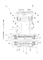
- FIG. 1 is a partial cross-sectional view of an electric disc brake according to this embodiment
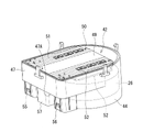
- FIG. 2 is a perspective view showing a control section inside a control section housing employed in the electric disc brake according to the present embodiment
- an electric disc brake 1 is an electric brake device that generates a braking force by driving an electric motor 26, and is employed as a braking device during normal running of a vehicle.
- the inner side of the vehicle will be referred to as the inner side
- the outer side of the vehicle will be referred to as the outer side
- the inner side may be referred to as one end side
- the outer side may be referred to as the other end side.
- An electric disc brake 1 includes a pair of inner brake pads 2 and outer brake pads 3, a caliper 4, and a pair of inner brake pads 2 and an outer brake pad 3, which are arranged on both sides in the axial direction across a disc rotor D attached to a rotating portion of a vehicle. is provided. 1, illustration of the disk rotor D is omitted.
- the electric disc brake 1 is configured as a caliper floating type.
- a pair of inner brake pads 2 and outer brake pads 3 and a caliper 4 are attached to a carrier 5 fixed to a non-rotating portion such as a knuckle (not shown) of a vehicle. supported so as to be movable to
- the braking members correspond to a pair of inner brake pad 2 and outer brake pad 3, which are friction pads.
- the member to be braked corresponds to the disc rotor D.
- the mounting member corresponds to the carrier 5 .
- the carrier 5 is integrally connected to a pair of pin connecting portions 8, 8 to which slide pins 38, 38, which will be described later, are respectively connected, and a pair of pin connecting portions 8, 8. , and inner and outer side support portions 9 and 10 for independently supporting the inner and outer brake pads 2 and 3, respectively.
- the pair of pin connecting portions 8, 8 are arranged at intervals along the rotation direction of the disk rotor D.
- Each pin connecting portion 8 is integrally connected to an inner side arm portion 13 of an inner side support portion 9 to be described later and an outer side arm portion 20 of an outer side support portion 10 to be described later, and each pin sliding portion 31 to be described later. protruded on the side.
- Each pin connecting portion 8 protrudes from a position between the inner side arm portion 13 of the inner side support portion 9 and the outer side arm portion 20 of the outer side support portion 10 .
- the inner-side support portion 9 includes a pair of inner-side arm portions 13, 13 arranged at intervals along the rotation direction of the disk rotor D and extending in a direction perpendicular to the axial direction of the slide pin 38, which will be described later. and an inner beam portion 14 that connects the ends of the pair of inner side arm portions 13, 13 opposite to the pin connecting portion 8.
- the inner brake pad 2 is supported inside the pair of inner side arm portions 13, 13 so as to be movable along the axial direction of the disc rotor D.
- a pair of fixing portions 16, 16 for fixing the carrier 5 to a non-rotating portion of the vehicle are integrally connected to both ends of the inner beam portion 14 in the rotation direction of the disk rotor D.
- the outer side support portion 10 includes a pair of outer side arm portions 20, 20 arranged on the outer side with a space from the pair of inner side arm portions 13, 13 of the inner side support portion 9, and the pair of outer side arms. and an outer side beam portion 21 that connects the ends of the portions 20 , 20 opposite to the pin connecting portion 8 .
- the outer brake pad 3 is supported inside the pair of outer side arm portions 20, 20 so as to be movable along the axial direction of the disc rotor D. As shown in FIG.
- the carrier 5 is fixed to a non-rotating portion of the vehicle via a pair of fixing portions 16 , 16 of the inner side support portion 9 .
- the caliper 4 has a caliper main body 25 which is the main body of the caliper 4, an electric motor 26, and the caliper main body 25.
- the caliper 4 has a speed reduction mechanism 60 and a rotation-to-linear motion conversion mechanism 61, and receives the driving force from the electric motor 26. , and a braking mechanism 28 that transmits power to the piston 36 in the cylinder portion 29 of the caliper body 25 via a speed reduction mechanism 60 and a rotation/linear motion conversion mechanism 61 .
- the caliper body 25 is arranged on the base end side facing the inner brake pad 2, and has a cylindrical cylinder portion 29 that opens facing the inner brake pad 2, and an outer side extending from the cylinder portion 29 across the disk rotor D.
- FIG. 2 in order to make it easier to understand, detailed plan view shapes such as raised portions extending from the pair of claw portions 30, 30 toward the other end side are omitted.
- a substantially circular cylinder bore 34 that opens from the other end face is formed in the cylinder portion 29 .
- a piston 36 is inserted into the cylinder bore 34 so as to be non-rotatable relative to the cylinder portion 29 and movable along the axial direction.
- the piston 36 has, for example, a cup shape consisting of a cylindrical portion and a bottom portion, and its axial direction coincides with the axial direction of the disk rotor D and the slide pin 38 .
- the driving force from the electric motor 26 is transmitted to the piston 36 in the cylinder portion 29 via the braking mechanism 28, and the piston 36 advances toward the disc rotor D while the bottom of the piston 36 acts as an inner brake.
- the pad 2 is pressed.
- the brake is released, the driving force from the electric motor 26 is transmitted to the piston 36 via the braking mechanism 28, so that the piston 36 retreats from the disk rotor D.
- a pair of pin sliding portions 31 , 31 are integrally protruding outward along the rotational direction of the disk rotor D on the cylinder portion 29 of the caliper body 25 .
- Each pin sliding portion 31 extends along the axial direction of the disk rotor D.
- Each pin sliding portion 31 is formed in a bottomed cylindrical shape with the other end surface open.
- a pair of slide pins 38, 38 are inserted into the pair of pin sliding portions 31, 31 so as to be slidable along the axial direction.
- Each of the pin sliding portions 31 , 31 is arranged closer to one end than the pair of pin connecting portions 8 , 8 of the carrier 5 .
- the slide pin 38 extends along the axial direction of the disk rotor D. As shown in FIG.
- the slide pin 38 is formed in an elongated circular cross section.
- a pair of slide pins 38, 38 are slidably inserted in the respective pin sliding portions 31, 31 provided in the cylinder portion 29 from the other end side along the axial direction.
- a pair of slide pins 38 , 38 are connected to respective corresponding pin connections 8 , 8 of the carrier 5 .
- Pin boots 39, 39 having expandable bellows are provided to cover the slide pins 38, 38, respectively.
- the caliper main body 25 (caliper 4) slides against the carrier 5 by sliding the pair of slide pins 38, 38 in the respective pin sliding portions 31, 31 provided in the cylinder portion 29. It can be slidably supported along the axial direction.
- the electric motor 26 is electrically connected to a control unit (ECU) 42 for controlling its rotation.
- the electric motor 26 is arranged on the one end side from the bottom of the cylinder portion 29 .
- the electric motor 26 is housed in a cylindrical motor gear housing 44 .
- the electric motor 26 is arranged inside the motor gear housing 44 at one end thereof. Specifically, the electric motor 26 is arranged across a motor gear housing 44 and a control section housing 47 which will be described later.
- the axial direction of the rotating shaft 27 of the electric motor 26 coincides with the axial direction of the disk rotor D. As shown in FIG.
- the rotating shaft 27 of the electric motor 26 and the cylinder bore 34 of the cylinder portion 29 are arranged substantially concentrically.
- the control unit 42 receives, for example, a detection signal from a detection sensor that responds to a request from the driver, a detection sensor that detects various situations requiring braking, and a wheel speed detection sensor that detects the wheel speed.
- a detection signal from a rotation angle detection means (not shown) for detecting the rotation angle of the rotation shaft 27 of the electric motor 26, and the thrust force (pressing force ), the rotation of the electric motor 26 (rotation direction, rotation speed, etc.) is controlled based on various detection signals such as a detection signal from a thrust sensor (not shown) that detects .
- the control unit 42 is arranged on the one end side from the electric motor 26 .
- the electric motor 26 has a control section 42 (a first control board section 51 and a second control board section 52, which will be described later), and inner and outer brake pads 2 and 3 along the axial direction of the rotating shaft 27. It is arranged so as to be sandwiched between
- the controller 42 is housed in one end of the controller housing 47 .
- the controller housing 47 is integrally connected with the motor gear housing 44 .
- the control unit housing 47 is configured to protrude from the motor gear housing 44 toward the side opposite to the inner and outer beam portions 14 and 21 of the inner and outer support portions 9 and 10 .
- the other end surface 47A is exposed from the motor gear housing 44 to the side opposite to the inner side and outer side beam portions 14, 21 of the inner side and outer side support portions 9, 10. be.
- a cover member 48 closes an opening on one end side of the control unit housing 47 . 3, illustration of the cover member 48 is omitted.
- control unit 42 is composed of a control substrate unit 50 having at least one control substrate 49 .
- the control unit 42 is composed of a control substrate unit 50 that is formed by bending one long control substrate 49 into two layers.
- control unit 42 is composed of the control board unit 50 which is formed by bending one long control board 49 into two layers.
- the control board section 50 (control section 42) is a two-layered structure formed by bending one control board 49, and includes the inner side and outer side support sections 9 and 10 and the inner side and outer side beam sections 14 and 21, respectively.
- a first control board portion 51 having one side of the redundant control system arranged on one end side in the extending direction (a shaded area in FIG. 3), and two layers of inner side and outer side support portions 9 , 10, and a second control board portion 52 having the other of the redundant control systems (the hatched area in FIG. 3), which is arranged on the other end side in the extending direction of the inner and outer beam portions 14, 21 of the beam portions 14, 21.
- the first control board section 51 and the second control board section 52 are arranged on the same plane as the control board section 50 (on the same plane of the first layer and on the same plane of the second layer). .
- control board section 50 is arranged such that the two control boards 49, 49 are arranged on the same plane, and the first control board section 51 is arranged on one control board 49.
- the second control board section 52 may be arranged on the other control board 49 .
- the first control board portion 51 is arranged in one of two layers (first layer or second layer) of the two layers formed by bending one long control board 49, and the first control board portion 51 is arranged in the second layer.
- the control board 52 may be arranged in either one of the two layers (first layer or second layer).
- the control unit 42 includes a first connector 55 used for inputting one of the signals to be fed and redundant, a second connector 56 used to input the other of the signals to be fed and redundant, and a wheel speed detection sensor. (not shown) are connected to third connectors 57 used for inputting signals from the terminals.
- the first connector 55 is used to input various detection signals, such as the detection signals from the detection sensor corresponding to the driver's request and the detection signals from the detection sensors that detect various situations requiring braking. Therefore, in addition to inputting one of the redundant signals, it can also be used for inputting other signals.
- the second connector 56 is also used for inputting the various detection signals described above, and is used for inputting other signals in addition to the other input of the signal to be made redundant. can also be used.
- both the first connector 55 and the second connector 56 are used for inputting the same signal in addition to power supply.
- the first connector 55 and the second connector 56 have the same function.
- both the first connector 55 and the second connector 56 are used for inputting the same signal in addition to power supply. It may be used only for the input of redundant signals.
- the third connector 57 can also be used for inputting signals from various other detection sensors in addition to the signal input from the wheel speed detection sensor.
- the third connector 57 connected to the control unit 42 is provided, but instead of the third connector 57, a signal from the wheel speed detection sensor is input via the integrated controller of the vehicle. , and the signal input may be electrically connected to the controller 42 .
- the first connector 55, the second connector 56, and the third connector 57 extend from the other end surface 47A of the control unit housing 47 and project from the motor gear housing 44 to the other end surface 47A. It protrudes toward the end side.
- the first connector 55 , the second connector 56 and the third connector 57 connect the inner and outer brake pads 2 , 3 along the axial direction of the rotating shaft 27 of the electric motor 26 from the other end surface 47 ⁇ /b>A of the control unit housing 47 . protruding toward.
- the first connector 55, the second connector 56 and the third connector 57 are arranged in a row.
- first connector 55, the second connector 56 and the third connector 57 extend along the same direction as the extending direction of the inner and outer beam portions 14 and 21 of the inner and outer side support portions 9 and 10. They are arranged in a row.
- the third connector 57 is arranged so as to be sandwiched between the first connector 55 and the second connector 56 .
- the first connector 55, the second connector 56, and the third connector 57 are configured as independent connectors, respectively.
- the second connector 56 may be configured as a second connector portion
- the third connector 57 may be configured as a third connector portion
- these first to third connector portions may be integrated into one connector.
- the first connector portion and the second connector portion may be integrated into one connector, or the first connector portion and the third connector portion may be integrated into one connector.
- the second connector portion and the third connector portion may be integrated into one connector.
- the first connector 55 is arranged on the first control board section 51 side of the control board section 50 (control section 42) and connected to each other.
- the second connector 56 is arranged on the second control board portion 52 side of the control board portion 50 (control portion 42) and connected to each other.
- the first connector 55 may be arranged on either one side of the first or second control board portions 51 and 52 of the control board portion 50 (control portion 42) and connected to each other. may be arranged on the other side of either the first or second control board portions 51 and 52 of the control board portion 50 (control portion 42) and connected to each other.
- the third connector 57 is connectable to both the first control board portion 51 and the second control board portion 52 of the control board portion 50 (the control portion 42), and the first control board portion 51 is connected to the third connector 57.
- the connection state and the connection state of the second control board portion 52 to the third connector 57 are configured to be controllably switchable by switching (not shown) or the like.
- the first connector 55 is connected to the first control board portion 51 and the second connector 56 is connected to the second control board portion 52.
- the first connector 55 is connected to the first control board portion 51 and the second control board portion 52
- the second connector 56 may be connected to both the first control board portion 51 and the second control board portion 52 .
- the first connector 55 may be connected to both the first control board portion 51 and the second control board portion 52 and the second connector 56 may be connected to the second control board portion 52 .
- the braking mechanism 28 is provided in the caliper body 25, and includes a speed reduction mechanism 60 that increases rotational torque from the electric motor 26, and a rotary motion from the speed reduction mechanism 60 that converts the rotary motion into linear motion to move the piston. and a rotation-to-linear motion conversion mechanism 61 for applying thrust to 36 .
- Rotation from the rotary shaft 27 of the electric motor 26 is transmitted to the reduction mechanism 60 .
- the reduction mechanism 60 increases the rotational torque from the electric motor 26 and transmits it to the rotation/linear motion conversion mechanism 61 .
- a planetary gear reduction mechanism or the like is adopted as the reduction mechanism 60 .
- the speed reduction mechanism 60 is accommodated in the motor gear housing 44 on the other end side (cylinder portion 29 side).
- the rotation/linear motion conversion mechanism 61 is arranged between the bottom portion of the cylinder portion 29 and the piston 36 within the cylinder bore 34 of the cylinder portion 29 .
- the rotation-to-linear motion converting mechanism 61 converts the rotary motion from the deceleration mechanism 60 into linear motion and applies thrust to the piston 36 .
- a ball screw mechanism, a ball and ramp mechanism, or the like is adopted as the rotation/linear motion conversion mechanism 61 .
- detection signals from detection sensors that detect various situations that require braking are made redundant.
- signals are input to the first or second control board portions 51, 52 of the control portion 42 (control board portion 50) via the first or second connectors 55, 56, respectively.
- Signals including redundant signals may be input to the first and second control board sections 51 and 52 of the control section 42 (control board section 50) via the first and second connectors 55 and 56.
- a detection signal from a wheel speed detection sensor that detects wheel speed is input to the first or second control board portion 51 or 52 of the control portion 42 via the third connector 57 .
- a detection signal from the rotation angle detection means for detecting the rotation angle of the rotation shaft 27 of the electric motor 26, the inner and outer brake pads 2, A detection signal or the like from a thrust sensor that detects the thrust from 3 to the disk rotor D is input. Furthermore, power is supplied to the control unit 42 from a power supply device (not shown) through the first or second connectors 55 and 56 .
- the first and second control board sections 51 and 52 of the control section 42 control rotation of the rotating shaft 27 of the electric motor 26 in the positive direction, that is, in the braking direction.
- the rotation of the electric motor 26 is transmitted to the reduction mechanism 60 of the braking mechanism 28 .
- the rotation increased by the deceleration mechanism 60 is transmitted to the rotation/linear motion conversion mechanism 61 of the braking mechanism 28 .
- the rotation-to-linear motion converting mechanism 61 converts the rotary motion from the speed reduction mechanism 60 into linear motion to move the piston 36 forward.
- the caliper body 25 (caliper 4) moves in the axial direction within the pair of pin sliding portions 31, 31 of the pair of slide pins 38, 38 due to the reaction force against the pressing force to the inner brake pad 2 by the piston 36.
- the outer brake pad 3 in contact with the pair of claw portions 30 presses the disk rotor D.
- the disk rotor D is sandwiched between the pair of inner and outer brake pads 2 and 3 to generate a frictional force, which in turn generates a braking force for the vehicle.
- the rotary shaft 27 of the electric motor 26 is controlled to rotate in the opposite direction, that is, in the release direction, by commands from the first or second control board portions 51 and 52 of the control portion 42 (control board portion 50).
- the rotation in the opposite direction is transmitted to the rotation/linear motion conversion mechanism 61 via the reduction mechanism 60 of the braking mechanism 28 .
- the piston 36 retreats and returns to its initial state, and the braking force exerted by the pair of inner and outer brake pads 2 and 3 on the disc rotor D is released.
- both the first control board portion 51 and the second control board portion 52 of the control board portion 50 are normal, and either the first connector 55 or the second connector 56 is in a normal state. Even if one of the connectors fails, the power supply and control unit 42 can control the rotation of the electric motor 26 by using the other of the first connector 55 and the second connector 56 . Also, in the control board section 50, when both the first connector 55 and the second connector 56 are normal and either the first control board section 51 or the second control board section 52 is malfunctioning, Even if there is, it is possible to control the rotation of the electric motor 26 by the other of the first control board portion 51 and the second control board portion 52 which are normal. Furthermore, since the signal from the wheel speed detection sensor is directly input to the control board section 50 via the third connector 57, noise in the signal from the wheel speed detection sensor input to the control board section 50 is reduced. be able to.
- the first connector 55 connected to the control unit 42 and used for inputting one of the power supply and redundant signal
- the first connector 55 connected to the control unit 42
- a second connector 56 used to input the other of the power supply and redundant signal
- a third connector 57 connected to the control unit 42 and used to input the signal from the wheel speed sensor.
- the control unit 42 when braking and releasing the brakes during normal running, the control unit 42 is in a normal state and either the first connector 55 or the second connector 56 malfunctions. Even in a situation where a , in other words, redundancy can be provided.
- the signal from the wheel speed detection sensor is directly input to the control unit 42 via the third connector 57, noise in the signal from the wheel speed detection sensor input to the control unit 42 can be reduced. It is possible to improve the accuracy of the control related to the braking action by the control unit 42 .
- the control board section 50 which is the control section 42 includes the first control board section 51 having one of the redundant control systems and the other of the redundant control systems.
- a first connector 55 is connected to the first control board portion 51 and a second connector 56 is connected to the second control board portion 52 .
- both the first connector 55 and the second connector 56 are in a normal state, and in the control board section 50, either the first control board section 51 or the second control board section 52 has malfunctioned. Even in such a situation, it is possible to control the rotation of the electric motor 26 by the other of the first control board portion 51 and the second control board portion 52, and to ensure a normal braking action. can.
- the first connector 55 is connected to both the first control board portion 51 and the second control board portion 52
- the second connector 56 is connected to the first control board portion 51 and the second control board portion 52.
- An embodiment in which both of the second control board portions 52 are connected may be adopted.
- the other of the first connector 55 or the second connector 56 and the other of the first control board portion 51 or the second control board portion 52, which are both normal are connected to the power supply and the rotation of the electric motor 26. Control is possible, normal braking action can be ensured, and redundancy can be improved as compared with the electric disc brake 1 according to the present embodiment described above.
- the third connector 57 can be connected to both the first control board portion 51 and the second control board portion 52, and the first control board for the third connector 57
- the connection state of the portion 51 and the connection state of the second control board portion 52 with respect to the third connector 57 can be controlled and switched.
- the third connector 57 The signal of the wheel speed sensor from can be input to either the first control board section 51 or the second control board section 52 which is normal.
- the signal of the wheel speed sensor from the third connector 57 can be normally input to the control board section 50 , and the rotation of the electric motor 26 can be normally controlled from the control board section 50 .
- the control board portion 50 is configured such that the first control board portion 51 and the second control board portion 52 are arranged on the same plane, and the first control board portion 51 and the second control board portion 52 are arranged on the same plane.
- a first connector 55 is arranged on the board portion 51 side and connected to each other, and a second connector 56 is arranged on the second control board portion 52 side and connected to each other.
- the third connector 57 is arranged so as to be sandwiched between the first connector 55 and the second connector 56 . Further, according to this embodiment, space efficiency can be improved, and an increase in the size of the electric disc brake 1 can be suppressed.
- the first connector 55 is connected to both the first control board portion 51 and the second control board portion 52
- the second connector 56 is connected to the second control board portion 52.
- Embodiments may be employed that connect to the .
- the normal first connector 55 and the first or Power supply and rotation of the electric motor 26 can be controlled by the other of the second control board portions 51 and 52, and a normal braking action can be ensured. 1 can improve its redundancy.
- the inner and outer brake pads 2 and 3, the first control board portion 51 and the second control board portion 52 are arranged in the axial direction of the rotating shaft 27 of the electric motor 26. are arranged with the electric motor 26 interposed therebetween, and the first connector 55, the second connector 56 and the third connector 57 are arranged on the inner and outer brake pads 2 and 3 side in the axial direction of the rotating shaft 27 of the electric motor 26. In other words, it is arranged to extend toward the inner and outer brake pads 2,3.
- the electric disc brake 1 it is possible to suppress an increase in size along the axial direction of the disc rotor D (the axial direction of the rotating shaft 27 of the electric motor 26).
- the present invention is not limited to the above-described embodiments, and includes various modifications.
- the above-described embodiments have been described in detail in order to explain the present invention in an easy-to-understand manner, and are not necessarily limited to those having all the configurations described.
- part of the configuration of one embodiment can be replaced with the configuration of another embodiment, and the configuration of another embodiment can be added to the configuration of one embodiment.
Landscapes
- Engineering & Computer Science (AREA)
- Mechanical Engineering (AREA)
- General Engineering & Computer Science (AREA)
- Transportation (AREA)
- Physics & Mathematics (AREA)
- Fluid Mechanics (AREA)
- Braking Arrangements (AREA)
- Braking Systems And Boosters (AREA)
Abstract
Description
Claims (10)
- 電動ブレーキ装置であって、
制動部材を被制動部材に押圧する制動機構と、
該制動機構を駆動させる電動モータと、
該電動モータに接続される制御部と、
該制御部に接続され、給電及び所定信号の入力のうち、少なくともいずれか一方に用いられる第1コネクタ部と、
前記制御部に接続され、少なくとも前記第1コネクタ部の用途の一部を含む第2コネクタ部と、
前記制御部に接続され、車輪速に関する信号の入力に用いられる信号入力部と、を備える、電動ブレーキ装置。 - 請求項1に記載の電動ブレーキ装置であって、
前記信号入力部は、第3コネクタ部である、電動ブレーキ装置。 - 請求項2に記載の電動ブレーキ装置であって、
前記制御部は、少なくとも1枚以上の制御基板を有する制御基板部である、電動ブレーキ装置。 - 請求項3に記載の電動ブレーキ装置であって、
前記制御基板部は、冗長化される制御系の一方を有する第1制御基板部と、冗長化される他方の制御系を有する第2制御基板部と、を備え、
前記第1コネクタ部は、前記第1制御基板部及び第2制御基板部の両方に接続され、
前記第2コネクタ部は、前記第1制御基板部及び第2制御基板部の両方に接続される、電動ブレーキ装置。 - 請求項3に記載の電動ブレーキ装置であって、
前記制御基板部は、冗長化される制御系の一方を有する第1制御基板部と、冗長化される制御系の他方を有する第2制御基板部と、を備え、
前記第1コネクタ部は、前記第1制御基板部に接続され、
前記第2コネクタ部は、前記第2制御基板部に接続される、電動ブレーキ装置。 - 請求項5に記載の電動ブレーキ装置であって、
前記第3コネクタ部は、前記第1制御基板部及び第2制御基板部の両方に接続可能であり、
前記第3コネクタ部に対する前記第1制御基板部の接続状態と、前記第3コネクタ部に対する前記第2制御基板部の接続状態とが制御的に切り替え可能に構成される、電動ブレーキ装置。 - 請求項6に記載の電動ブレーキ装置であって、
前記第1制御基板部と前記第2制御基板部とは、同じ平面上に位置しており、
前記第1コネクタ部及び前記第2コネクタ部は、前記第3コネクタ部を挟むように配置され、前記第1コネクタ部が前記第1制御基板部に接続されると共に、前記第2コネクタ部が前記第2制御基板部に接続される、電動ブレーキ装置。 - 請求項3に記載の電動ブレーキ装置であって、
前記制御基板部は、冗長化される制御系の一方を有する第1制御基板部と、冗長化される制御系の他方を有する第2制御基板部と、を備え、
前記第1コネクタ部は、前記第1制御基板部及び第2制御基板部の両方に接続され、
前記第2コネクタ部は、前記第2制御基板部に接続される、電動ブレーキ装置。 - 請求項3に記載の電動ブレーキ装置であって、
前記電動モータの回転軸線の方向において、前記制動部材と前記制御基板部とは、前記電動モータを挟んで配置されており、
前記第1コネクタ部、前記第2コネクタ部及び前記第3コネクタ部は、前記電動モータの回転軸線の方向において、前記制動部材側に延出するように配置されている、電動ブレーキ装置。 - 電動ディスクブレーキであって、
車両の非回転部に固定され、ディスクロータの外周側を跨いで設けられる取付部材と、
該取付部材に前記ディスクロータの軸方向に移動可能に設けられ、摩擦パッドを前記ディスクロータに押圧する制動機構を含むキャリパ本体と、
前記制動機構を駆動させる電動モータと、
該電動モータに接続され、冗長化される制御系の一方を有する第1制御基板部と、前記電動モータに接続され、冗長化される制御系の他方を有する第2制御基板部とを備える制御基板と、
前記第1制御基板部に接続され、給電及び冗長化される信号の一方の入力に用いられる第1コネクタと、
前記第2制御基板部に接続され、給電及び冗長化される信号の他方の入力に用いられる第2コネクタと、
前記第1制御基板部及び前記第2制御基板部の両方に接続可能であり、車輪速検出センサからの信号の入力に用いられる第3コネクタと、を備える、電動ディスクブレーキ。
Priority Applications (5)
| Application Number | Priority Date | Filing Date | Title |
|---|---|---|---|
| US18/278,952 US12704163B2 (en) | 2021-05-28 | 2022-02-28 | Electric brake apparatus and electric disk brake |
| DE112022002806.8T DE112022002806T5 (de) | 2021-05-28 | 2022-02-28 | Elektrische Bremsvorrichtung und elektrische Scheibenbremse |
| KR1020237020222A KR102876648B1 (ko) | 2021-05-28 | 2022-02-28 | 전동 브레이크 장치 및 전동 디스크 브레이크 |
| JP2023524007A JP7442018B2 (ja) | 2021-05-28 | 2022-02-28 | 電動ブレーキ装置及び電動ディスクブレーキ |
| CN202280022000.4A CN117083211A (zh) | 2021-05-28 | 2022-02-28 | 电动制动器装置和电动盘式制动器 |
Applications Claiming Priority (2)
| Application Number | Priority Date | Filing Date | Title |
|---|---|---|---|
| JP2021090328 | 2021-05-28 | ||
| JP2021-090328 | 2021-05-28 |
Publications (1)
| Publication Number | Publication Date |
|---|---|
| WO2022249609A1 true WO2022249609A1 (ja) | 2022-12-01 |
Family
ID=84228545
Family Applications (1)
| Application Number | Title | Priority Date | Filing Date |
|---|---|---|---|
| PCT/JP2022/008190 Ceased WO2022249609A1 (ja) | 2021-05-28 | 2022-02-28 | 電動ブレーキ装置及び電動ディスクブレーキ |
Country Status (6)
| Country | Link |
|---|---|
| US (1) | US12704163B2 (ja) |
| JP (1) | JP7442018B2 (ja) |
| KR (1) | KR102876648B1 (ja) |
| CN (1) | CN117083211A (ja) |
| DE (1) | DE112022002806T5 (ja) |
| WO (1) | WO2022249609A1 (ja) |
Families Citing this family (2)
| Publication number | Priority date | Publication date | Assignee | Title |
|---|---|---|---|---|
| EP4495450B1 (en) * | 2022-03-16 | 2026-08-12 | Astemo, Ltd. | Disc brake and carrier therefor |
| FR3171261A1 (fr) * | 2025-01-15 | 2026-07-17 | Hitachi Astemo France | logement de réception d'une carte électronique formant une Pièce de protection de connecteur pour frein électrique et frein comportant une telle pièce de protection |
Citations (4)
| Publication number | Priority date | Publication date | Assignee | Title |
|---|---|---|---|---|
| JP2000168527A (ja) * | 1998-12-11 | 2000-06-20 | Nec Home Electronics Ltd | アンチロックブレーキ装置用基幹モジュール |
| JP2008105643A (ja) * | 2006-10-27 | 2008-05-08 | Advics:Kk | ブレーキ液圧制御装置の負圧発生防止装置。 |
| JP5195360B2 (ja) * | 2008-01-24 | 2013-05-08 | 株式会社アドヴィックス | ブレーキ液圧制御装置 |
| JP2019048594A (ja) * | 2017-09-12 | 2019-03-28 | 日立オートモティブシステムズ株式会社 | ブレーキ制御装置 |
Family Cites Families (11)
| Publication number | Priority date | Publication date | Assignee | Title |
|---|---|---|---|---|
| US7203070B2 (en) * | 2003-12-03 | 2007-04-10 | Tyco Electronics Canada, Ltd. | Sealed electronic input/output module |
| DE102004059546A1 (de) * | 2004-12-09 | 2006-06-22 | Lucas Automotive Gmbh | Elektronisches System zum Betreiben einer elektromechanischen Feststell-Bremsanlage |
| DE102011084534A1 (de) * | 2010-10-18 | 2012-04-19 | Continental Teves Ag & Co. Ohg | Fehlersichere Parkbremse für Kraftfahrzeuge |
| DE102015206572A1 (de) * | 2014-05-15 | 2015-11-19 | Continental Teves Ag & Co. Ohg | Bremsanlage für Kraftfahrzeuge |
| JP6680053B2 (ja) | 2016-04-06 | 2020-04-15 | 株式会社デンソー | 駆動装置、および、これを用いた電動パワーステアリング装置 |
| JP6735931B2 (ja) * | 2017-10-13 | 2020-08-05 | 日立オートモティブシステムズ株式会社 | 電動ブレーキ装置 |
| EP4656474A1 (en) * | 2019-03-29 | 2025-12-03 | HL Mando Corporation | Brake system |
| WO2020204510A1 (ko) * | 2019-03-29 | 2020-10-08 | 주식회사 만도 | 전자식 브레이크 시스템 및 그 제어 방법 |
| DE102019207517A1 (de) * | 2019-05-22 | 2020-11-26 | Volkswagen Aktiengesellschaft | Bremssteuersystem |
| JP2021090328A (ja) | 2019-12-06 | 2021-06-10 | アイシン・エィ・ダブリュ株式会社 | インバータ制御装置 |
| CN117917199A (zh) * | 2021-12-21 | 2024-04-19 | 日立安斯泰莫株式会社 | 电子控制装置及电动制动装置 |
-
2022
- 2022-02-28 JP JP2023524007A patent/JP7442018B2/ja active Active
- 2022-02-28 CN CN202280022000.4A patent/CN117083211A/zh active Pending
- 2022-02-28 WO PCT/JP2022/008190 patent/WO2022249609A1/ja not_active Ceased
- 2022-02-28 KR KR1020237020222A patent/KR102876648B1/ko active Active
- 2022-02-28 DE DE112022002806.8T patent/DE112022002806T5/de active Pending
- 2022-02-28 US US18/278,952 patent/US12704163B2/en active Active
Patent Citations (4)
| Publication number | Priority date | Publication date | Assignee | Title |
|---|---|---|---|---|
| JP2000168527A (ja) * | 1998-12-11 | 2000-06-20 | Nec Home Electronics Ltd | アンチロックブレーキ装置用基幹モジュール |
| JP2008105643A (ja) * | 2006-10-27 | 2008-05-08 | Advics:Kk | ブレーキ液圧制御装置の負圧発生防止装置。 |
| JP5195360B2 (ja) * | 2008-01-24 | 2013-05-08 | 株式会社アドヴィックス | ブレーキ液圧制御装置 |
| JP2019048594A (ja) * | 2017-09-12 | 2019-03-28 | 日立オートモティブシステムズ株式会社 | ブレーキ制御装置 |
Also Published As
| Publication number | Publication date |
|---|---|
| US20240141964A1 (en) | 2024-05-02 |
| DE112022002806T5 (de) | 2024-03-14 |
| JPWO2022249609A1 (ja) | 2022-12-01 |
| JP7442018B2 (ja) | 2024-03-01 |
| US12704163B2 (en) | 2026-08-11 |
| KR20230107334A (ko) | 2023-07-14 |
| KR102876648B1 (ko) | 2025-10-24 |
| CN117083211A (zh) | 2023-11-17 |
Similar Documents
| Publication | Publication Date | Title |
|---|---|---|
| KR102932508B1 (ko) | 전자기계식 브레이크 시스템 | |
| JP7442018B2 (ja) | 電動ブレーキ装置及び電動ディスクブレーキ | |
| WO2021215157A1 (ja) | ディスクブレーキ | |
| JP7847158B2 (ja) | 電子制御装置及び電動ブレーキ装置 | |
| JP7394149B2 (ja) | ディスクブレーキ | |
| JP4304418B2 (ja) | 電動ディスクブレーキ | |
| CN112272741B (zh) | 盘式制动器 | |
| CN112334677B (zh) | 盘式制动器 | |
| JP4055037B2 (ja) | 電動ディスクブレーキ | |
| JP7588255B2 (ja) | ディスクブレーキ | |
| JP7851419B2 (ja) | 電動ブレーキ装置 | |
| WO2020195921A1 (ja) | 電動ブレーキ装置 | |
| JP3928149B2 (ja) | 電動ディスクブレーキ | |
| JP4051650B2 (ja) | 電動ディスクブレーキ | |
| JP7649722B2 (ja) | ディスクブレーキ | |
| KR102870712B1 (ko) | 차량의 제동장치 | |
| JP7398345B2 (ja) | ディスクブレーキ及び遊星歯車減速機構 | |
| KR20260041647A (ko) | 브레이크 어셈블리 및 브레이크 어셈블리용 어버트먼트 클립 | |
| JP7061558B2 (ja) | ディスクブレーキ | |
| WO2024166671A1 (ja) | 電動ブレーキ装置 | |
| KR20250025990A (ko) | 브레이크 장치 및 이를 구비하는 차량 | |
| JPH11280800A (ja) | 電動ブレーキ装置 | |
| KR20260017844A (ko) | 브레이크 장치 | |
| JP2007255480A (ja) | ビルトイン型のディスクブレーキキャリパ構造 |
Legal Events
| Date | Code | Title | Description |
|---|---|---|---|
| 121 | Ep: the epo has been informed by wipo that ep was designated in this application |
Ref document number: 22810890 Country of ref document: EP Kind code of ref document: A1 |
|
| ENP | Entry into the national phase |
Ref document number: 2023524007 Country of ref document: JP Kind code of ref document: A |
|
| ENP | Entry into the national phase |
Ref document number: 20237020222 Country of ref document: KR Kind code of ref document: A |
|
| WWE | Wipo information: entry into national phase |
Ref document number: 18278952 Country of ref document: US |
|
| WWE | Wipo information: entry into national phase |
Ref document number: 202280022000.4 Country of ref document: CN |
|
| WWE | Wipo information: entry into national phase |
Ref document number: 112022002806 Country of ref document: DE |
|
| 122 | Ep: pct application non-entry in european phase |
Ref document number: 22810890 Country of ref document: EP Kind code of ref document: A1 |