WO2022249546A1 - 移動体管理システムおよび移動体管理方法 - Google Patents
移動体管理システムおよび移動体管理方法 Download PDFInfo
- Publication number
- WO2022249546A1 WO2022249546A1 PCT/JP2022/003744 JP2022003744W WO2022249546A1 WO 2022249546 A1 WO2022249546 A1 WO 2022249546A1 JP 2022003744 W JP2022003744 W JP 2022003744W WO 2022249546 A1 WO2022249546 A1 WO 2022249546A1
- Authority
- WO
- WIPO (PCT)
- Prior art keywords
- mobile
- user terminal
- management system
- unit
- user
- Prior art date
- Legal status (The legal status is an assumption and is not a legal conclusion. Google has not performed a legal analysis and makes no representation as to the accuracy of the status listed.)
- Ceased
Links
Images









Classifications
-
- G—PHYSICS
- G06—COMPUTING OR CALCULATING; COUNTING
- G06Q—INFORMATION AND COMMUNICATION TECHNOLOGY [ICT] SPECIALLY ADAPTED FOR ADMINISTRATIVE, COMMERCIAL, FINANCIAL, MANAGERIAL OR SUPERVISORY PURPOSES; SYSTEMS OR METHODS SPECIALLY ADAPTED FOR ADMINISTRATIVE, COMMERCIAL, FINANCIAL, MANAGERIAL OR SUPERVISORY PURPOSES, NOT OTHERWISE PROVIDED FOR
- G06Q30/00—Commerce
- G06Q30/06—Buying, selling or leasing transactions
- G06Q30/0645—Rental transactions; Leasing transactions
-
- G—PHYSICS
- G06—COMPUTING OR CALCULATING; COUNTING
- G06Q—INFORMATION AND COMMUNICATION TECHNOLOGY [ICT] SPECIALLY ADAPTED FOR ADMINISTRATIVE, COMMERCIAL, FINANCIAL, MANAGERIAL OR SUPERVISORY PURPOSES; SYSTEMS OR METHODS SPECIALLY ADAPTED FOR ADMINISTRATIVE, COMMERCIAL, FINANCIAL, MANAGERIAL OR SUPERVISORY PURPOSES, NOT OTHERWISE PROVIDED FOR
- G06Q30/00—Commerce
- G06Q30/06—Buying, selling or leasing transactions
-
- G—PHYSICS
- G06—COMPUTING OR CALCULATING; COUNTING
- G06Q—INFORMATION AND COMMUNICATION TECHNOLOGY [ICT] SPECIALLY ADAPTED FOR ADMINISTRATIVE, COMMERCIAL, FINANCIAL, MANAGERIAL OR SUPERVISORY PURPOSES; SYSTEMS OR METHODS SPECIALLY ADAPTED FOR ADMINISTRATIVE, COMMERCIAL, FINANCIAL, MANAGERIAL OR SUPERVISORY PURPOSES, NOT OTHERWISE PROVIDED FOR
- G06Q50/00—Information and communication technology [ICT] specially adapted for implementation of business processes of specific business sectors, e.g. utilities or tourism
- G06Q50/10—Services
-
- G—PHYSICS
- G07—CHECKING-DEVICES
- G07C—TIME OR ATTENDANCE REGISTERS; REGISTERING OR INDICATING THE WORKING OF MACHINES; GENERATING RANDOM NUMBERS; VOTING OR LOTTERY APPARATUS; ARRANGEMENTS, SYSTEMS OR APPARATUS FOR CHECKING NOT PROVIDED FOR ELSEWHERE
- G07C9/00—Individual registration on entry or exit
- G07C9/00174—Electronically operated locks; Circuits therefor; Nonmechanical keys therefor, e.g. passive or active electrical keys or other data carriers without mechanical keys
- G07C9/00309—Electronically operated locks; Circuits therefor; Nonmechanical keys therefor, e.g. passive or active electrical keys or other data carriers without mechanical keys operated with bidirectional data transmission between data carrier and locks
-
- H—ELECTRICITY
- H04—ELECTRIC COMMUNICATION TECHNIQUE
- H04W—WIRELESS COMMUNICATION NETWORKS
- H04W4/00—Services specially adapted for wireless communication networks; Facilities therefor
- H04W4/02—Services making use of location information
- H04W4/023—Services making use of location information using mutual or relative location information between multiple location based services [LBS] targets or of distance thresholds
-
- H—ELECTRICITY
- H04—ELECTRIC COMMUNICATION TECHNIQUE
- H04W—WIRELESS COMMUNICATION NETWORKS
- H04W4/00—Services specially adapted for wireless communication networks; Facilities therefor
- H04W4/02—Services making use of location information
- H04W4/029—Location-based management or tracking services
-
- G—PHYSICS
- G07—CHECKING-DEVICES
- G07C—TIME OR ATTENDANCE REGISTERS; REGISTERING OR INDICATING THE WORKING OF MACHINES; GENERATING RANDOM NUMBERS; VOTING OR LOTTERY APPARATUS; ARRANGEMENTS, SYSTEMS OR APPARATUS FOR CHECKING NOT PROVIDED FOR ELSEWHERE
- G07C2209/00—Indexing scheme relating to groups G07C9/00 - G07C9/38
- G07C2209/60—Indexing scheme relating to groups G07C9/00174 - G07C9/00944
- G07C2209/63—Comprising locating means for detecting the position of the data carrier, i.e. within the vehicle or within a certain distance from the vehicle
Definitions
- the present disclosure relates to a mobile management system and a mobile management method.
- Temporary use services that allow users to temporarily use mobile objects such as bicycles, such as rental bicycles and shared bicycles, are known.
- this temporary use service there is also a technology that uses the user's mobile terminal with GPS (Global Positioning System) function to automate a series of necessary functions such as user authentication, locking and unlocking of mobile bodies, and anti-theft. proposed (see, for example, Patent Document 1).
- GPS Global Positioning System
- the moving object can be automatically locked, for example, when it is temporarily parked, it is possible to prevent theft due to forgetting to lock the vehicle, thereby reducing the risk of theft.
- the theft risk is higher than when the door can be automatically locked. It is desirable that such a difference be properly reflected in the usage fee of the mobile unit.
- a mobile body management system searches for a relative position between a user terminal carried by a user who temporarily uses a mobile body and the mobile body, a detection unit that detects a distance based on a relative position; a lock control unit that automatically locks the moving object according to the distance detected by the detection unit; and a charge calculation unit for changing the charge for use of the mobile unit.
- FIG. 1 is a schematic explanatory diagram of a moving body management method according to an embodiment of the present disclosure
- FIG. 1 is a diagram illustrating a configuration example of a mobile management system according to an embodiment of the present disclosure
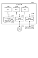
- FIG. 1 is a block diagram showing a configuration example of an in-vehicle device according to an embodiment of the present disclosure
- FIG. 4 is a block diagram showing a configuration example of a return port according to an embodiment of the present disclosure
- FIG. 2 is a block diagram showing a configuration example of a user terminal according to an embodiment of the present disclosure
- FIG. 1 is a block diagram showing a configuration example of a server device according to an embodiment of the present disclosure
- FIG. 2 is a diagram (part 1) showing state transitions in the mobile management system according to the embodiment of the present disclosure
- FIG. 2 is a diagram (part 2) showing state transitions in the mobile management system according to the embodiment of the present disclosure
- FIG. 3 is a diagram (part 1) showing a specific example of a UI screen presented on a user terminal
- FIG. 10 is a diagram (part 2) showing a specific example of a UI screen presented on the user terminal
- FIG. 13 is a diagram (part 3) showing a specific example of a UI screen presented on the user terminal
- FIG. 12 is a diagram (part 4) showing a specific example of a UI screen presented on the user terminal
- FIG. 10 is a diagram (No.
- FIG. 16 is a diagram (No. 6) showing a specific example of a UI screen presented on the user terminal;
- FIG. 12 is a diagram (No. 7) showing a specific example of a UI screen presented on the user terminal;
- FIG. 12 is a diagram (part 8) showing a specific example of a UI screen presented on the user terminal;
- FIG. 12 is a diagram (part 9) showing a specific example of a UI screen presented on the user terminal;
- FIG. 10 is a diagram (No. 10) showing a specific example of a UI screen presented on the user terminal;
- FIG. 11 is a diagram (No.
- FIG. 12 is a diagram (No. 12) showing a specific example of a UI screen presented on the user terminal;
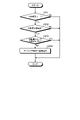
- 10 is a flowchart (part 1) showing a processing procedure executed by the mobile body management system;
- 2 is a flowchart (part 2) showing a processing procedure executed by the mobile body management system;
- 10 is a flowchart (part 3) showing a processing procedure executed by the mobile body management system;
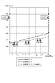
- FIG. 2 is an explanatory diagram (part 1) of usage fees;
- FIG. 2 is an explanatory diagram (part 2) of usage fees;
- FIG. 2 is a hardware configuration diagram showing an example of a computer that implements functions of an in-vehicle device;
- the mobile body temporarily used by the user U is the bicycle B.
- the type of the mobile body is not limited as long as it is a mobile body to which the temporary use service is applied.
- FIG. 1 is a schematic explanatory diagram of a moving body management method according to an embodiment of the present disclosure.
- the mobile management system 1 includes an in-vehicle device 10, a user terminal 50, and a server device 100.
- the in-vehicle device 10 is a computer mounted on the bicycle B.
- the user terminal 50 is a terminal device used by a user U who uses the bicycle B temporarily.
- the server device 100 is a device that is managed and operated by a business that provides a temporary use service for the bicycle B. As shown in FIG.
- the existing technology using such a moving object management system 1 needs further improvement in terms of accurately grasping the situation of the bicycle B and appropriately reflecting the difference in risk during temporary use in the usage fee. There is room.
- the bicycle B can be automatically locked, for example, when it is temporarily parked, it is possible to prevent theft due to forgetting to lock the bicycle, thereby reducing the risk of theft.
- the user U manually locks the door, the theft risk is higher than when the door can be automatically locked. It is desirable that such a difference be appropriately reflected in the usage fee for Bicycle B.
- the moving body management method searches for the relative position between the user terminal 50 carried by the user U who temporarily uses the bicycle B and the bicycle B, detects the distance based on the searched relative position, and detects The bicycle B is automatically locked according to the determined distance, and the usage fee for the bicycle B is dynamically changed according to the usage state of the automatic lock.
- the mobile object management system 1 first manages the bicycle B in two modes: “automatic locking mode” and “manual locking mode”.
- the “automatic locking mode” is a mode in which the bicycle B can be automatically locked according to the distance between the in-vehicle device 10 and the user terminal 50 .
- the mobile body management system 1 searches for the relative positions of the in-vehicle device 10 and the user terminal 50 (step S1). Then, automatic locking is performed according to the distance between the in-vehicle device 10 and the user terminal 50 based on the searched relative position (step S2). Further, theft is detected based on the change in position during automatic locking (step S3).
- step S1 a communication path that directly connects the in-vehicle device 10 and the user terminal 50 using short-range wireless communication such as Bluetooth (registered trademark) is used. Establish Then, while observing the radio wave intensity and error rate in the short-range wireless communication, the relative position between the in-vehicle device 10 and the user terminal 50 is constantly searched, and the relative position information is shared by both.
- short-range wireless communication such as Bluetooth (registered trademark)
- the radio wave intensity is attenuated in proportion to the square of the distance in an ideal space, and the error rate is affected by the distance, the presence of obstacles, reflections, etc. .
- step S2 when it is determined that the user U has left the predetermined proximity range R1 based on the searched relative position, it is regarded as temporary parking, and the bicycle is parked. Automatically lock B. In addition, when the user U returns from the outside to the inside of the close range R1, automatic unlocking is performed.
- step S3 the theft of the mobile object is detected based on whether or not the mobile object is moving with the user U using the change in the position of the in-vehicle device 10 by the GPS and the above-described relative position information. To detect.
- the mobile management system 1 allows the user U to manually lock the door (step S4).
- Whether or not the user U uses the automatic locking mode can be selected by the user U on the UI (User Interface) screen of the user terminal 50 at the time of contract.
- UI User Interface
- FIGS. 9 to 20 Various specific examples of the UI screen will be described later with reference to FIGS. 9 to 20.
- the in-vehicle device 10 and the user terminal 50 may become unusable due to low battery.
- the user U is using the automatic locking mode, it cannot be continued, so switching to the manual locking mode is performed. That is, the mode may change during temporary use.
- the server device 100 dynamically changes the usage fee according to the mode and its change, in addition to the basic usage fee system (step S4). As a result, the difference in risk during temporary use can be appropriately reflected in the usage fee.
- the moving body management method searches for the relative position between the user terminal 50 carried by the user U temporarily using the bicycle B and the bicycle B, and detects the distance based on the searched relative position. , the bicycle B is automatically locked according to the detected distance, and the charge for the bicycle B is dynamically changed according to the usage state of the automatic lock.
- the moving body management method it is possible to accurately grasp the situation of Bicycle B and appropriately reflect the difference in risk during temporary use in the usage fee.
- FIG. 2 is a diagram showing a configuration example of the mobile management system 1 according to the embodiment of the present disclosure.
- the mobile body management system 1 includes one or more in-vehicle devices 10 , one or more return ports 30 , one or more user terminals 50 , and a server device 100 .
- the in-vehicle device 10, the user terminal 50, and the server device 100 are interconnected by a network N such as the Internet, a mobile phone network, etc., and exchange data with each other via the network N. is provided to be able to transmit and receive.
- a network N such as the Internet, a mobile phone network, etc.
- the in-vehicle device 10 and the user terminal 50 are provided so that they can directly transmit and receive data to and from each other by short-range wireless communication. Also, the in-vehicle device 10 is provided so as to be able to receive radio waves emitted by the return port 30 .
- the in-vehicle device 10 is a computer mounted on the bicycle B, as already mentioned.
- the return port 30 is a device corresponding to the return place of the returned bicycle B, and is provided so as to be able to transmit radio waves to the surroundings.
- the user terminal 50 is a mobile terminal device used by each user U, and executes various information processing according to the operation content of the user U via various UIs such as GUI (Graphical User Interface) and voice UI. .
- GUI Graphic User Interface
- voice UI voice UI
- the user terminal 50 is a tablet terminal, a mobile phone such as a smart phone, a PDA (Personal Digital Assistant), or the like. Also, the user terminal 50 may be, for example, a wearable device or the like provided so that the user U can wear it.
- the server device 100 is realized, for example, as a cloud server, and provides a user U with a user authentication, a service contract, locking/unlocking of the bicycle B, anti-theft function, etc. for the user U. It is a server device that provides usage services.
- FIG. 3 is a block diagram showing a configuration example of the in-vehicle device 10 according to the embodiment of the present disclosure. It should be noted that FIG. 3 and FIGS. 4 to 6 shown later show only the constituent elements necessary for explaining the features of this embodiment, and the description of general constituent elements is omitted.
- each component illustrated in FIGS. 3 to 6 is functionally conceptual and does not necessarily need to be physically configured as illustrated.
- the specific form of distribution/integration of each block is not limited to the one shown in the figure. It is possible to integrate and configure.
- Bicycle B further includes an in-vehicle sensor section 2 and a locking mechanism 3 .
- the in-vehicle sensor unit 2 is a group of various sensors mounted on the bicycle B.
- In-vehicle sensor unit 2 includes, for example, a GPS sensor.
- the lock mechanism 3 is a mechanism that locks or unlocks the bicycle B under the control of a lock control section 14c (to be described later) or manually.
- the in-vehicle device 10 includes a communication unit 11, a short-range wireless communication unit 12, a storage unit 13, and a control unit 14.
- the communication unit 11 is realized by, for example, a NIC (Network Interface Card) or the like.
- the communication unit 11 is wirelessly connected to the server device 100 via the network N, and transmits and receives various types of information to and from the server device 100 .
- the short-range wireless communication unit 12 is implemented by, for example, a NIC.
- the short-range wireless communication unit 12 is connected to the return port 30 and the user terminal 50 by a short-range wireless communication method, and transmits and receives various information to and from the return port 30 and the user terminal 50 .
- a short-range wireless communication method in addition to the Bluetooth described above, NFC (Near Field Communication), UWB (Ultra Wide Band), or the like can be used.
- the storage unit 13 is realized, for example, by a semiconductor memory device such as RAM (Random Access Memory), ROM (Read Only Memory), flash memory, or a storage device such as a hard disk or optical disk.
- a semiconductor memory device such as RAM (Random Access Memory), ROM (Read Only Memory), flash memory, or a storage device such as a hard disk or optical disk.
- the storage unit 13 stores detection-related information 13a.
- the detection-related information 13a is information including various detection parameters used for detection processing by the detection unit 14b, which will be described later.
- the control unit 14 is a controller, and various programs (not shown) stored in the storage unit 13 are executed using the RAM as a work area, for example, by a CPU (Central Processing Unit) or MPU (Micro Processing Unit). It is realized by being Also, the control unit 14 can be realized by an integrated circuit such as an ASIC (Application Specific Integrated Circuit) or an FPGA (Field Programmable Gate Array).
- ASIC Application Specific Integrated Circuit
- FPGA Field Programmable Gate Array
- the control unit 14 has an acquisition unit 14a, a detection unit 14b, a lock control unit 14c, and a notification unit 14d, and implements or executes the information processing functions and actions described below.
- the acquisition unit 14a acquires sensing data from the in-vehicle sensor unit 2, such as GPS sensor values.
- the detection unit 14 b searches for the relative position with respect to the user terminal 50 via the short-range wireless communication unit 12 and detects the distance from the user terminal 50 . Further, the detection unit 14b detects the theft of the bicycle B by determining whether the bicycle B is moving with the user U based on the sensing data acquired by the acquisition unit 14a and the above-described relative position information.
- the lock control unit 14c locks or unlocks the bicycle B with the lock mechanism 3 based on the relative positions of the in-vehicle device 10 and the user terminal 50 or the operation of the user U.
- the notification unit 14d performs various notifications to, for example, the user terminal 50 according to state transitions in the mobile management system 1, which will be described later.
- the return port 30 has a radio wave transmitter 31 .
- the radio wave transmission unit 31 transmits radio waves to a predetermined peripheral range.
- the transmitted radio waves are received by the in-vehicle device 10 of bicycle B stopped at the return port 30 .
- the in-vehicle device 10 Upon receiving such radio waves, the in-vehicle device 10 detects that the bicycle B has been returned and is parked at the return port 30 .
- the user terminal 50 includes a terminal sensor unit 51, a UI unit 52, a communication unit 53, a short-range wireless communication unit 54, a storage unit 55, and a control unit 56. .
- the terminal sensor unit 51 is a group of various sensors mounted on the user terminal 50.
- Terminal sensor unit 51 includes, for example, a GPS sensor, an acceleration sensor, a gyro sensor, and the like.
- the UI unit 52 is a component that provides a user interface for the user U, and includes an operation unit, a display unit, and an audio output unit.
- the UI unit is implemented by, for example, a touch panel display, a speaker, or the like.
- the communication unit 53 is realized by, for example, a NIC, like the communication unit 11 described above.
- the communication unit 53 is wirelessly connected to the server device 100 via the network N, and transmits and receives various information to and from the server device 100 .
- the short-range wireless communication unit 54 is implemented by, for example, a NIC, like the short-range wireless communication unit 12 described above.
- the short-range wireless communication unit 54 is connected to the in-vehicle device 10 by a short-range wireless communication method, and transmits and receives various types of information to and from the in-vehicle device 10 .
- Bluetooth, NFC, UWB, etc. mentioned above can be used as the short-range wireless communication method.
- the storage unit 55 is realized by semiconductor memory devices such as RAM, ROM, and flash memory, or storage devices such as hard disks and optical disks, like the storage unit 13 described above.
- the storage unit 55 stores application information 55a.
- the application information 55a includes a program of a dedicated application for the temporary use service of the bicycle B executed by the control unit 56, and the like.
- the control unit 56 is a controller similar to the control unit 14 described above, and various programs stored in the application information 55a of the storage unit 55 are executed by the CPU, MPU, etc., using the RAM as a work area. It is realized by Also, the control unit 56 can be realized by an integrated circuit such as an ASIC or FPGA, for example.
- the control unit 56 has an acquisition unit 56a, a detection unit 56b, a state management unit 56c, and an application execution unit 56d, and implements or executes the information processing functions and actions described below.
- the acquisition unit 56a acquires sensing data from the terminal sensor unit 51, such as GPS sensor values.
- the detection unit 56 b searches for the relative position with the in-vehicle device 10 via the short-range wireless communication unit 12 and detects the distance from the in-vehicle device 10 .
- the state management unit 56c manages state transitions in the mobile management system 1. Such state transition will be described later with reference to FIGS. 7 and 8.
- FIG. Application execution unit 56d executes the above-described dedicated application based on application information 55a.
- the server apparatus 100 includes a communication section 101, a storage section 102, and a control section 103.
- FIG. 6 the server apparatus 100 includes a communication section 101, a storage section 102, and a control section 103.
- the communication unit 101 is realized by, for example, a NIC, like the communication unit 11 and the communication unit 53 described above.
- the communication unit 101 is wirelessly connected to the in-vehicle device 10 and the user terminal 50 via the network N, and transmits and receives various types of information to and from the in-vehicle device 10 and the user terminal 50 .
- the storage unit 102 like the storage unit 13 and the storage unit 55 described above, is implemented by semiconductor memory devices such as RAM, ROM, flash memory, or storage devices such as hard disks and optical disks.
- semiconductor memory devices such as RAM, ROM, flash memory, or storage devices such as hard disks and optical disks.
- the storage unit 102 stores usage charge calculation information 102a.
- the usage fee calculation information 102a includes various parameters related to fee calculation, such as a fee table used when a usage fee is calculated by a fee calculation unit 103d, which will be described later.
- the control unit 103 is a controller similar to the control unit 14 and the control unit 56 described above. It is realized by being Also, the control unit 103 can be realized by an integrated circuit such as an ASIC or FPGA, for example.
- the control unit 103 has an acquisition unit 103a, a usage contract management unit 103b, a theft countermeasure unit 103c, a charge calculation unit 103d, and a provision unit 103e, and implements or implements the information processing functions and actions described below. Run.
- the acquisition unit 103 a acquires various types of information from the in-vehicle device 10 and the user terminal 50 via the communication unit 101 .
- the use contract management unit 103b manages a use contract with the user U, that is, various information such as whether or not the automatic locking mode is used and the period of use.
- the theft countermeasure unit 103c When the in-vehicle device 10 detects that the bicycle B has been stolen, the theft countermeasure unit 103c notifies the user terminal 50 that the theft has been detected.
- the fee calculation unit 103d calculates usage fees according to state transitions and the like, which will be described later.
- the providing unit 103e provides the user terminal 50 via the communication unit 101 with various types of information generated in the server device 100, such as the toll calculation results and the usage status of the bicycle B up to the present time.
- FIG. 7 and 8 are diagrams (Part 1) and (Part 2) showing state transitions in the mobile management system 1 according to the embodiment of the present disclosure.
- the bicycle B when the bicycle is referred to as the bicycle B, it may be appropriately rephrased as the "in-vehicle device 10".
- the term "user terminal 50" when referring to the user U, the term "user terminal 50" may be appropriately used.
- FIGS. 9 to 25 will be referred to as appropriate in this description.
- 9 to 20 are diagrams (part 1) to (part 12) showing specific examples of UI screens presented on the user terminal 50.
- FIG. 21 to 23 are flowcharts (part 1) to (part 3) showing processing procedures executed by the mobile management system 1.
- FIG. 24 and 25 are explanatory diagrams (part 1) and (part 2) of usage fees.
- the automatic locking mode is entered and the state is "out of range during reservation (locked)" (S13).
- the bicycle B is automatically locked, which eliminates the possibility of forgetting to lock the bicycle and reduces the risk of theft.
- the manual locking mode is entered and the state is "manually reserved (locked)" (S19).
- the manual locking mode the bicycle B is locked manually, and the operability and the like are equivalent to those of the normal temporary use service.
- the detection unit 56b activates the radio wave transmission/reception unit of the short-range wireless communication unit 54, and similarly in the in-vehicle device 10, the detection unit 14b activates the radio wave transmission/reception unit of the short-range wireless communication unit 12. to try to connect.
- one of the in-vehicle device 10 and the user terminal 50 outputs sound through a speaker, and the other collects the sound with a microphone and determines the relative position from the volume of the volume. It's good. Further, at this time, by using the UI unit 52 to provide feedback to the user U as to whether the distance to the bicycle B is getting closer or farther, it is possible to navigate until reaching the bicycle B.
- the user terminal 50 that has received such unlocking information notifies the start of use (N1) via the UI unit 52, performs relative position calibration for determining whether it is within the proximity range R1, and performs "running" shown in FIG. (Unlocked)” state (S16). Note that the relative position calibration may be periodically updated while the vehicle is running.
- Temporary parking When the detection unit 14b determines that the relative position is outside the proximity range R1 during the "running (unlocked)" state, the lock control unit 14c automatically locks.
- the user terminal 50 that has received such locking information determines that the user U has left the bicycle B and is in the temporarily parked state, and the state management unit 56c makes the state transition to the “temporarily parked (locked)” state (S17). ).
- a lock notification (N2) is sent to the user U via a UI screen or the like as shown in FIG.
- the lock control unit 14c performs fail-safe processing so that the vehicle is not suddenly locked while driving even if the correct relative position cannot be obtained due to a failure of the detection unit 14b, radio wave interference, or the like.
- the lock control unit 14c determines whether or not the automatic lock mode is set (step S101). If the automatic locking mode is set (step S101, Yes), the lock control unit 14c then determines whether or not the bicycle B is moving (step S102).
- step S102 the lock control unit 14c subsequently determines whether or not the bicycle B and the user terminal 50 are in proximity (step S103).
- step S103 the lock control unit 14c locks the bicycle B (step S104) and ends the process.
- step S101, No if the bicycle B is moving (step S102, yes), or if the bicycle B and the user terminal 50 are close to each other (step S103, yes), terminates the process.
- the in-vehicle device 10 When receiving radio waves from the return port 30 while the vehicle is locked, the in-vehicle device 10 detects that the vehicle is stopped at the return port 30 and notifies the user terminal 50 of the fact. When the state management unit 56c recognizes that the bicycle B is parked at the return port 30 while it is locked (S13 to S15, S17 to S20, S22), it presents a UI screen as shown in FIG. to confirm whether to terminate the usage contract.
- the fee calculation unit 103d periodically calculates and displays the latest usage fee on the UI unit 52 of the user terminal 50 during the contract period. department.
- Theft report> The detection unit 14b determines whether the bicycle B is moving together with the user U or not using the change in the position of the bicycle B and the relative position information from the in-vehicle sensor unit 2 . Then, when not moving with the user U, the theft handling unit 103c reports the theft to the temporary use service provider.
- the detection unit 14b determines whether or not the automatic locking mode is set (step S201).
- the detection unit 14b subsequently determines whether or not the bicycle B is moving (step S202).
- step S202 the detection unit 14b subsequently determines whether or not the bicycle B and the user terminal 50 are in proximity.
- step S203, No the theft handling unit 103c reports the theft to the temporary use service provider (step S204), and the process ends.
- step S201, No if it is not in the automatic locking mode (step S201, No), if the bicycle B is not moving (step S202, No), or if the bicycle B and the user terminal 50 are close to each other (step S203, Yes) , the process ends.
- the theft handling unit 103c When the user U is nearby, the theft handling unit 103c also notifies the user U through a UI screen such as that shown in FIG. This may allow the red-handed offender to be apprehended at the scene. If the theft report is received and the user U is able to provide information about the theft to the temporary use service provider or find the location of the theft, the user U will be given some kind of incentive.
- incentives include, for example, a gift of a coupon for the next use, addition of points in a point program provided by a service provider, and the like.
- the state management unit 56c notifies the user U of the manual mode change that the automatic locking mode has been switched to the manual locking mode through the UI screens shown in FIGS. 18 and 19 (N7 to N10). . Then, the use of the temporary use service is continued in the manual locking mode (S19-S22).
- the user U In the manual locking mode, when it is detected that the user U is walking based on the acceleration sensor of the terminal sensor unit 51, etc., the user U is instructed to lock the lock through a UI screen such as that shown in FIG. Call attention. For the alert, the user U self-reports the confirmation result by, for example, tapping "locked" shown in FIG. 20 after confirming the lock. In the manual locking mode, it cannot be confirmed that the user U has left the bicycle B. Therefore, when the walking of the user U is detected, the user's attention may be periodically and repeatedly called to an extent that is not bothersome.
- the procedure for switching to the manual locking mode first determines whether or not the automatic locking mode is set (step S301). If the automatic locking mode is set (step S301, Yes), then it is determined whether or not the battery of the bicycle B is low (step S302).
- step S302 If the battery of the bicycle B is not low (step S302, No), then it is determined whether the battery of the user terminal 50 is low (step S303). If the battery of the user terminal 50 is not low (step S303, No), the process ends.
- step S302 When the battery of the bicycle B is low (step S302, Yes), or when the battery of the user terminal 50 is low (step S303, Yes), the distance measurement is interrupted (step S304), and the manual lock mode is entered. is switched to (step S305).
- step S306 the process ends.
- step S301, No it is determined whether or not the battery of bicycle B is low. Then, when the battery of the bicycle B is low (step S307, Yes), it is determined whether or not the user U is walking (step S308).
- step S308 if the user U is walking (step S308, Yes), the user U is alerted to lock the door (step S309). Then, the process ends.
- step S307, No if the battery of the bicycle B is not low (step S307, No) or if the user U is not walking (step S308, No), the process ends.
- FIG. 24 shows the difference in usage fees between the automatic locking mode and the manual locking mode.
- FIG. 25 shows the difference in usage fees when switching to the manual locking mode occurs.
- the basic charge for using the manual locking mode all the time is 600 yen/hour
- the discount for using the automatic locking mode is -1 yen/minute (10% off).
- a discount of -0.5 yen/minute for the time during temporary parking in the automatic locking mode and the remaining usage time when returning to the return port 30 early total of 15 when combined with the automatic locking mode discount
- the usage fee is 10% off while driving, and if you return it early, the remaining time will be calculated at 15% off. For example, if the use ends immediately after the start of use, the charge will be 510 yen (15% off), and if the car is returned after running for 60 minutes, the charge will be 540 yen (10% off).
- the difference in the burden of insurance premiums according to the risk of theft and management responsibility is dynamically reflected in the usage fee, depending on whether the mobile object is in automatic locking mode or temporarily parked. be able to.
- the time during which the automatic locking mode with a low risk of theft is used can be accurately grasped, so the usage fee during the automatic locking mode can be reduced.
- the time during which the automatic locking mode with a low risk of theft is used can be accurately grasped, so the usage fee during the automatic locking mode can be reduced.
- it is possible to finely automatically lock the vehicle according to the accurate detection of the distance between the in-vehicle device 10 and the user terminal 50 it is possible to more accurately grasp whether the vehicle is running or temporarily parked.
- each component of each device illustrated is functionally conceptual and does not necessarily need to be physically configured as illustrated.
- the specific form of distribution and integration of each device is not limited to the illustrated one, and all or part of them can be functionally or physically distributed and integrated in arbitrary units according to various loads and usage conditions. Can be integrated and configured.
- FIG. 26 is a hardware configuration diagram showing an example of a computer 1000 that implements the functions of the in-vehicle device 10.
- Computer 1000 has CPU 1100 , RAM 1200 , ROM 1300 , storage 1400 , communication interface 1500 and input/output interface 1600 .
- bus 1050 Each part of computer 1000 is connected by bus 1050 .
- the CPU 1100 operates based on programs stored in the ROM 1300 or storage 1400, and controls each section. For example, CPU 1100 expands programs stored in ROM 1300 or storage 1400 into RAM 1200 and executes processes corresponding to various programs.
- the ROM 1300 stores a boot program such as BIOS (Basic Input Output System) executed by the CPU 1100 when the computer 1000 is started, and programs dependent on the hardware of the computer 1000.
- BIOS Basic Input Output System
- the storage 1400 is a computer-readable recording medium that non-temporarily records programs executed by the CPU 1100 and data used by such programs.
- the storage 1400 is a recording medium that records an information processing program according to the present disclosure, which is an example of the program data 1450 .
- a communication interface 1500 is an interface for connecting the computer 1000 to an external network 1550 .
- CPU 1100 receives data from another device or transmits data generated by CPU 1100 to another device via communication interface 1500 .
- the input/output interface 1600 is an interface for connecting the input/output device 1650 and the computer 1000 .
- CPU 1100 can receive data from an input device such as a keyboard or mouse via input/output interface 1600 .
- the CPU 1100 can transmit data to an output device such as a display, speaker, or printer via the input/output interface 1600 .
- the input/output interface 1600 may function as a media interface for reading a program or the like recorded on a predetermined recording medium.
- Media include, for example, optical recording media such as DVD (Digital Versatile Disc) and PD (Phase change rewritable disk), magneto-optical recording media such as MO (Magneto-Optical disk), tape media, magnetic recording media, semiconductor memories, etc. is.
- the CPU 1100 of the computer 1000 implements the functions of the control unit 14 by executing the information processing program loaded on the RAM 1200.
- the storage 1400 also stores an information processing program according to the present disclosure and data in the storage unit 13 .
- CPU 1100 reads and executes program data 1450 from storage 1400 , as another example, these programs may be acquired from another device via external network 1550 .
- the mobile object management system 1 provides user terminal 50 carried by user U who temporarily uses bicycle B (corresponding to an example of a “mobile object”) and bicycle B.
- a detection unit 14b that searches for a relative position with and detects a distance based on the searched relative position
- a lock control unit 14c that automatically locks the bicycle B according to the distance detected by the detection unit 14b
- an automatic and a fee calculation unit 103d that dynamically changes the usage fee of the bicycle B according to the usage state of the lock.
- the present technology can also take the following configuration.
- a detection unit that searches for a relative position between a user terminal carried by a user who temporarily uses the mobile body and the mobile body, and detects a distance based on the searched relative position; a lock control unit that automatically locks the moving object according to the distance detected by the detection unit; a fee calculation unit that dynamically changes the usage fee of the mobile unit according to the usage state of the automatic lock; A mobile object management system.
- the lock control unit When the user indicates an intention to allow the use of the automatic locking via the user terminal, the automatic locking is performed.
- the mobile management system according to (1) above.
- the detection unit is searching for the relative position when the user terminal is within a predetermined search range including the mobile object; The mobile management system according to (1) or (2) above.
- the lock control unit When the detection unit detects that the user terminal is within a predetermined proximity area included in the search area, the automatic unlocking is performed.
- the user terminal is After the automatic unlocking is performed by the lock control unit, the relative position is calibrated in the proximity range while the user is on the mobile object.
- the lock control unit When the detection unit detects that the user terminal is outside the close range, the automatic locking is performed.
- the user terminal is When the automatic locking is performed by the lock control unit, the moving body is considered to be in a state of being temporarily parked; The mobile management system according to (6) above.
- the lock control unit When the detection unit detects a functional deterioration of the mobile object or the user terminal, disabling the use of the automatic locking and switching the locking of the mobile object to manual.
- the mobile management system according to (7) above. (9) The fee calculation unit calculating the usage fee so that the usage fee is cheaper when the automatic locking is used than when the automatic locking is not used; The mobile management system according to (7) or (8) above. (10) The fee calculation unit calculating the usage fee so as not to increase or decrease while the moving object is in the temporarily parked state; The mobile management system according to (7), (8) or (9) above.
- the detection unit is searching for the relative position while using short-range wireless communication; The mobile management system according to any one of (3) to (10).
- the detection unit is Searching for the relative position using the short-range wireless communication when the user terminal is within a predetermined communication range of the mobile object, which is the search range;
- the mobile management system according to (11) above.
- the detection unit is detecting theft of the mobile object if the mobile object is moving but the relative positions of the mobile object and the user terminal are not close to each other when the automatic locking can be used;
- the mobile management system according to any one of (1) to (12) above.
- a mobile object management method executed by one or more computers included in a mobile object management system, searching for a relative position between a user terminal carried by a user who temporarily uses the mobile body and the mobile body, and detecting a distance based on the searched relative position; automatically locking the moving object according to the distance detected in the detecting; dynamically changing the usage fee of the mobile unit according to the usage state of the automatic locking; mobile object management method, including
Landscapes
- Business, Economics & Management (AREA)
- Engineering & Computer Science (AREA)
- Accounting & Taxation (AREA)
- Computer Networks & Wireless Communication (AREA)
- Physics & Mathematics (AREA)
- Finance (AREA)
- General Physics & Mathematics (AREA)
- Signal Processing (AREA)
- General Business, Economics & Management (AREA)
- Strategic Management (AREA)
- Marketing (AREA)
- Theoretical Computer Science (AREA)
- Economics (AREA)
- Development Economics (AREA)
- Tourism & Hospitality (AREA)
- Primary Health Care (AREA)
- Human Resources & Organizations (AREA)
- General Health & Medical Sciences (AREA)
- Health & Medical Sciences (AREA)
- Telephone Function (AREA)
- Alarm Systems (AREA)
Priority Applications (2)
| Application Number | Priority Date | Filing Date | Title |
|---|---|---|---|
| JP2023523971A JPWO2022249546A1 (https=) | 2021-05-27 | 2022-02-01 | |
| US18/560,131 US20240233002A1 (en) | 2021-05-27 | 2022-02-01 | Moving object management system and moving object management method |
Applications Claiming Priority (2)
| Application Number | Priority Date | Filing Date | Title |
|---|---|---|---|
| JP2021089401 | 2021-05-27 | ||
| JP2021-089401 | 2021-05-27 |
Publications (1)
| Publication Number | Publication Date |
|---|---|
| WO2022249546A1 true WO2022249546A1 (ja) | 2022-12-01 |
Family
ID=84229730
Family Applications (1)
| Application Number | Title | Priority Date | Filing Date |
|---|---|---|---|
| PCT/JP2022/003744 Ceased WO2022249546A1 (ja) | 2021-05-27 | 2022-02-01 | 移動体管理システムおよび移動体管理方法 |
Country Status (3)
| Country | Link |
|---|---|
| US (1) | US20240233002A1 (https=) |
| JP (1) | JPWO2022249546A1 (https=) |
| WO (1) | WO2022249546A1 (https=) |
Cited By (1)
| Publication number | Priority date | Publication date | Assignee | Title |
|---|---|---|---|---|
| JP7731607B1 (ja) | 2024-08-01 | 2025-09-01 | 株式会社Luup | モビリティ管理方法、モビリティ管理システム及びプログラム。 |
Citations (5)
| Publication number | Priority date | Publication date | Assignee | Title |
|---|---|---|---|---|
| JP2002117237A (ja) * | 2000-10-11 | 2002-04-19 | Denso Corp | リスク細分型自動車保険システムおよびリスク細分型自動車保険運用装置 |
| JP2003081061A (ja) * | 2001-09-11 | 2003-03-19 | Denso Corp | 車両盗難防止システム |
| JP2004013534A (ja) * | 2002-06-06 | 2004-01-15 | Mitsubishi Electric Corp | 盗難通報装置、及び、盗難通報システム |
| KR20120047697A (ko) * | 2010-11-04 | 2012-05-14 | 주식회사 썬하이브리드 | 자전거 통합관리 시스템 |
| KR20120084192A (ko) * | 2011-01-19 | 2012-07-27 | 신민석 | 공영 자전거관리시스템 |
Family Cites Families (6)
| Publication number | Priority date | Publication date | Assignee | Title |
|---|---|---|---|---|
| JP2002133510A (ja) * | 2000-07-27 | 2002-05-10 | Sony Corp | 移動体レンタルシステム、移動体管理システム、移動体装置、移動体管理装置、移動体レンタル方法、移動体管理方法および記録媒体 |
| WO2014012564A1 (en) * | 2012-07-20 | 2014-01-23 | Velolock Ltd. | Locking device for a bicycle |
| US20150074004A1 (en) * | 2013-09-09 | 2015-03-12 | Joon Kyu Song | Bicycle rental system and method |
| JP6158655B2 (ja) * | 2013-09-19 | 2017-07-05 | 株式会社エイビット | 自転車シェアリングシステム |
| JP6387170B1 (ja) * | 2017-10-16 | 2018-09-05 | 株式会社パークランド | レンタル車両管理方法 |
| JP7146107B2 (ja) * | 2019-09-17 | 2022-10-04 | 本田技研工業株式会社 | 車両制御装置、車両制御方法、車両制御システム、プログラム、および記憶媒体 |
-
2022
- 2022-02-01 JP JP2023523971A patent/JPWO2022249546A1/ja active Pending
- 2022-02-01 US US18/560,131 patent/US20240233002A1/en not_active Abandoned
- 2022-02-01 WO PCT/JP2022/003744 patent/WO2022249546A1/ja not_active Ceased
Patent Citations (5)
| Publication number | Priority date | Publication date | Assignee | Title |
|---|---|---|---|---|
| JP2002117237A (ja) * | 2000-10-11 | 2002-04-19 | Denso Corp | リスク細分型自動車保険システムおよびリスク細分型自動車保険運用装置 |
| JP2003081061A (ja) * | 2001-09-11 | 2003-03-19 | Denso Corp | 車両盗難防止システム |
| JP2004013534A (ja) * | 2002-06-06 | 2004-01-15 | Mitsubishi Electric Corp | 盗難通報装置、及び、盗難通報システム |
| KR20120047697A (ko) * | 2010-11-04 | 2012-05-14 | 주식회사 썬하이브리드 | 자전거 통합관리 시스템 |
| KR20120084192A (ko) * | 2011-01-19 | 2012-07-27 | 신민석 | 공영 자전거관리시스템 |
Non-Patent Citations (1)
| Title |
|---|
| ANONYMOUS: "New SECOM Anshin My Car: Important matter manual for new type comprehensive automobile insurance policy", SECOM MANUAL, SECOM GENERAL INSURANCE, JP, JP, pages 1 - 12, XP009542643 * |
Cited By (2)
| Publication number | Priority date | Publication date | Assignee | Title |
|---|---|---|---|---|
| JP7731607B1 (ja) | 2024-08-01 | 2025-09-01 | 株式会社Luup | モビリティ管理方法、モビリティ管理システム及びプログラム。 |
| JP2026024117A (ja) * | 2024-08-01 | 2026-02-13 | 株式会社Luup | モビリティ管理方法、モビリティ管理システム及びプログラム。 |
Also Published As
| Publication number | Publication date |
|---|---|
| JPWO2022249546A1 (https=) | 2022-12-01 |
| US20240233002A1 (en) | 2024-07-11 |
Similar Documents
| Publication | Publication Date | Title |
|---|---|---|
| US10297097B2 (en) | Mobile device application for communicating with vehicles | |
| US9019129B2 (en) | Vehicle location in weak location signal scenarios | |
| US9080878B2 (en) | Automatic identification of vehicle location | |
| US20210174681A1 (en) | Parking occupancy estimation | |
| US20190173832A1 (en) | Electronic device, server, and control method and location information providing method for the electronic device | |
| US20120265874A1 (en) | Method and apparatus for sharing and managing resource availability | |
| CN112912918A (zh) | 用于管理共享车辆的方法、系统以及计算机可读存储介质 | |
| WO2015056269A1 (en) | Method, system and product for automatic parking payment and policy detection | |
| JP7396792B2 (ja) | 情報提供装置、情報提供方法、およびプログラム | |
| KR102261049B1 (ko) | 항만보안을 위한 블록체인 기반의 비정상 행동 탐지 방법 및 시스템 | |
| WO2022249546A1 (ja) | 移動体管理システムおよび移動体管理方法 | |
| CN115546911A (zh) | 便捷停车的方法、装置及介质 | |
| US20160078696A1 (en) | Access method and system with wearable controller | |
| JP6140354B1 (ja) | 対象物特定システムおよび駐車場管理システム | |
| Srisura et al. | Periodical mobile recommendation toward parking conflict reduction | |
| JP2015210642A (ja) | データ処理装置、車両管理サーバおよびコンピュータプログラム | |
| JP7265361B2 (ja) | 移動管理システムおよび移動管理方法 | |
| EP4038856B1 (en) | A method and system for providing access of an accessing device to a user | |
| US12307463B2 (en) | Managing data transactions | |
| US20240169341A1 (en) | Key in vehicle assurance service | |
| JP6482152B2 (ja) | 対象物特定方法および駐車場管理方法 | |
| WO2023114827A2 (en) | System and method for feature management | |
| JP2022067786A (ja) | 報酬提示装置 | |
| KR101519577B1 (ko) | 차량 대상 서비스 제공 방법 | |
| KR101527509B1 (ko) | 이종의 통신망을 이용한 컨텐츠 수신 방법 |
Legal Events
| Date | Code | Title | Description |
|---|---|---|---|
| 121 | Ep: the epo has been informed by wipo that ep was designated in this application |
Ref document number: 22810832 Country of ref document: EP Kind code of ref document: A1 |
|
| WWE | Wipo information: entry into national phase |
Ref document number: 2023523971 Country of ref document: JP |
|
| WWE | Wipo information: entry into national phase |
Ref document number: 18560131 Country of ref document: US |
|
| NENP | Non-entry into the national phase |
Ref country code: DE |
|
| 122 | Ep: pct application non-entry in european phase |
Ref document number: 22810832 Country of ref document: EP Kind code of ref document: A1 |