WO2022249409A1 - バッテリケース - Google Patents
バッテリケース Download PDFInfo
- Publication number
- WO2022249409A1 WO2022249409A1 PCT/JP2021/020275 JP2021020275W WO2022249409A1 WO 2022249409 A1 WO2022249409 A1 WO 2022249409A1 JP 2021020275 W JP2021020275 W JP 2021020275W WO 2022249409 A1 WO2022249409 A1 WO 2022249409A1
- Authority
- WO
- WIPO (PCT)
- Prior art keywords
- battery case
- vehicle
- rib
- frame
- bracket
- Prior art date
- Legal status (The legal status is an assumption and is not a legal conclusion. Google has not performed a legal analysis and makes no representation as to the accuracy of the status listed.)
- Ceased
Links
Images


Classifications
-
- B—PERFORMING OPERATIONS; TRANSPORTING
- B60—VEHICLES IN GENERAL
- B60K—ARRANGEMENT OR MOUNTING OF PROPULSION UNITS OR OF TRANSMISSIONS IN VEHICLES; ARRANGEMENT OR MOUNTING OF PLURAL DIVERSE PRIME-MOVERS IN VEHICLES; AUXILIARY DRIVES FOR VEHICLES; INSTRUMENTATION OR DASHBOARDS FOR VEHICLES; ARRANGEMENTS IN CONNECTION WITH COOLING, AIR INTAKE, GAS EXHAUST OR FUEL SUPPLY OF PROPULSION UNITS IN VEHICLES
- B60K1/00—Arrangement or mounting of electrical propulsion units
- B60K1/04—Arrangement or mounting of electrical propulsion units of the electric storage means for propulsion
-
- B—PERFORMING OPERATIONS; TRANSPORTING
- B60—VEHICLES IN GENERAL
- B60L—PROPULSION OF ELECTRICALLY-PROPELLED VEHICLES; SUPPLYING ELECTRIC POWER FOR AUXILIARY EQUIPMENT OF ELECTRICALLY-PROPELLED VEHICLES; ELECTRODYNAMIC BRAKE SYSTEMS FOR VEHICLES IN GENERAL; MAGNETIC SUSPENSION OR LEVITATION FOR VEHICLES; MONITORING OPERATING VARIABLES OF ELECTRICALLY-PROPELLED VEHICLES; ELECTRIC SAFETY DEVICES FOR ELECTRICALLY-PROPELLED VEHICLES
- B60L50/00—Electric propulsion with power supplied within the vehicle
- B60L50/50—Electric propulsion with power supplied within the vehicle using propulsion power supplied by batteries or fuel cells
- B60L50/60—Electric propulsion with power supplied within the vehicle using propulsion power supplied by batteries or fuel cells using power supplied by batteries
- B60L50/64—Constructional details of batteries specially adapted for electric vehicles
-
- H—ELECTRICITY
- H01—ELECTRIC ELEMENTS
- H01M—PROCESSES OR MEANS, e.g. BATTERIES, FOR THE DIRECT CONVERSION OF CHEMICAL ENERGY INTO ELECTRICAL ENERGY
- H01M50/00—Constructional details or processes of manufacture of the non-active parts of electrochemical cells other than fuel cells, e.g. hybrid cells
- H01M50/20—Mountings; Secondary casings or frames; Racks, modules or packs; Suspension devices; Shock absorbers; Transport or carrying devices; Holders
- H01M50/202—Casings or frames around the primary casing of a single cell or a single battery
-
- H—ELECTRICITY
- H01—ELECTRIC ELEMENTS
- H01M—PROCESSES OR MEANS, e.g. BATTERIES, FOR THE DIRECT CONVERSION OF CHEMICAL ENERGY INTO ELECTRICAL ENERGY
- H01M50/00—Constructional details or processes of manufacture of the non-active parts of electrochemical cells other than fuel cells, e.g. hybrid cells
- H01M50/20—Mountings; Secondary casings or frames; Racks, modules or packs; Suspension devices; Shock absorbers; Transport or carrying devices; Holders
- H01M50/249—Mountings; Secondary casings or frames; Racks, modules or packs; Suspension devices; Shock absorbers; Transport or carrying devices; Holders specially adapted for aircraft or vehicles, e.g. cars or trains
-
- B—PERFORMING OPERATIONS; TRANSPORTING
- B60—VEHICLES IN GENERAL
- B60K—ARRANGEMENT OR MOUNTING OF PROPULSION UNITS OR OF TRANSMISSIONS IN VEHICLES; ARRANGEMENT OR MOUNTING OF PLURAL DIVERSE PRIME-MOVERS IN VEHICLES; AUXILIARY DRIVES FOR VEHICLES; INSTRUMENTATION OR DASHBOARDS FOR VEHICLES; ARRANGEMENTS IN CONNECTION WITH COOLING, AIR INTAKE, GAS EXHAUST OR FUEL SUPPLY OF PROPULSION UNITS IN VEHICLES
- B60K11/00—Arrangement in connection with cooling of propulsion units
- B60K11/02—Arrangement in connection with cooling of propulsion units with liquid cooling
-
- B—PERFORMING OPERATIONS; TRANSPORTING
- B60—VEHICLES IN GENERAL
- B60K—ARRANGEMENT OR MOUNTING OF PROPULSION UNITS OR OF TRANSMISSIONS IN VEHICLES; ARRANGEMENT OR MOUNTING OF PLURAL DIVERSE PRIME-MOVERS IN VEHICLES; AUXILIARY DRIVES FOR VEHICLES; INSTRUMENTATION OR DASHBOARDS FOR VEHICLES; ARRANGEMENTS IN CONNECTION WITH COOLING, AIR INTAKE, GAS EXHAUST OR FUEL SUPPLY OF PROPULSION UNITS IN VEHICLES
- B60K1/00—Arrangement or mounting of electrical propulsion units
- B60K2001/003—Arrangement or mounting of electrical propulsion units with means for cooling the electrical propulsion units
- B60K2001/006—Arrangement or mounting of electrical propulsion units with means for cooling the electrical propulsion units the electric motors
-
- B—PERFORMING OPERATIONS; TRANSPORTING
- B60—VEHICLES IN GENERAL
- B60K—ARRANGEMENT OR MOUNTING OF PROPULSION UNITS OR OF TRANSMISSIONS IN VEHICLES; ARRANGEMENT OR MOUNTING OF PLURAL DIVERSE PRIME-MOVERS IN VEHICLES; AUXILIARY DRIVES FOR VEHICLES; INSTRUMENTATION OR DASHBOARDS FOR VEHICLES; ARRANGEMENTS IN CONNECTION WITH COOLING, AIR INTAKE, GAS EXHAUST OR FUEL SUPPLY OF PROPULSION UNITS IN VEHICLES
- B60K1/00—Arrangement or mounting of electrical propulsion units
- B60K1/04—Arrangement or mounting of electrical propulsion units of the electric storage means for propulsion
- B60K2001/0405—Arrangement or mounting of electrical propulsion units of the electric storage means for propulsion characterised by their position
- B60K2001/0438—Arrangement under the floor
-
- B—PERFORMING OPERATIONS; TRANSPORTING
- B60—VEHICLES IN GENERAL
- B60Y—INDEXING SCHEME RELATING TO ASPECTS CROSS-CUTTING VEHICLE TECHNOLOGY
- B60Y2306/00—Other features of vehicle sub-units
- B60Y2306/01—Reducing damages in case of crash, e.g. by improving battery protection
-
- H—ELECTRICITY
- H01—ELECTRIC ELEMENTS
- H01M—PROCESSES OR MEANS, e.g. BATTERIES, FOR THE DIRECT CONVERSION OF CHEMICAL ENERGY INTO ELECTRICAL ENERGY
- H01M2220/00—Batteries for particular applications
- H01M2220/20—Batteries in motive systems, e.g. vehicle, ship, plane
-
- Y—GENERAL TAGGING OF NEW TECHNOLOGICAL DEVELOPMENTS; GENERAL TAGGING OF CROSS-SECTIONAL TECHNOLOGIES SPANNING OVER SEVERAL SECTIONS OF THE IPC; TECHNICAL SUBJECTS COVERED BY FORMER USPC CROSS-REFERENCE ART COLLECTIONS [XRACs] AND DIGESTS
- Y02—TECHNOLOGIES OR APPLICATIONS FOR MITIGATION OR ADAPTATION AGAINST CLIMATE CHANGE
- Y02E—REDUCTION OF GREENHOUSE GAS [GHG] EMISSIONS, RELATED TO ENERGY GENERATION, TRANSMISSION OR DISTRIBUTION
- Y02E60/00—Enabling technologies; Technologies with a potential or indirect contribution to GHG emissions mitigation
- Y02E60/10—Energy storage using batteries
Definitions
- the present invention relates to battery cases.
- JP2936959B discloses an electric vehicle equipped with a battery as a drive source.
- JP2936959B includes a battery case formed by a center frame and side frames extending in the longitudinal direction of the vehicle, a front frame arranged in front of the vehicle, a rear frame arranged in the rear of the vehicle, and a cross member partitioning in the width direction of the vehicle.
- the battery is arranged on a mounting portion formed by arranging each frame and each member in a grid pattern. Further, the battery case is provided with a side sill outside the side frame in the width direction of the vehicle body.
- the electric vehicle described in JP2936959B has the above configuration, so that even if the load is input from the side of the vehicle, the load does not act directly on the battery. On the other hand, it is desired to further improve the durability against the load input to the side surface of the electric vehicle.
- An object of the present invention is to provide a technique for improving the durability against the load input to the side of an electric vehicle.
- a battery case that houses a battery for an electric vehicle.
- This battery case has a pair of side frames, cross members, and side brackets.
- the pair of side frames constitute left and right sidewalls of the battery case in the vehicle width direction, and extend along the vehicle front-rear direction.
- the cross member divides the internal space of the battery case in the longitudinal direction of the vehicle and extends from one side frame to the other side frame.
- the side bracket is fixed to the outer surface of the side frame and is used to attach the battery case to the vehicle body.
- the side frame has a frame rib extending in the vehicle width direction within the side frame, and the side bracket has a bracket rib extending in the vehicle width direction within the side bracket.
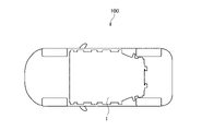
- FIG. 1 is a side see-through view showing essential parts of an electric vehicle equipped with a battery case according to an embodiment of the present invention.
- FIG. 2 is a perspective plan view of the essential parts of the electric vehicle equipped with the battery case according to the embodiment of the present invention, viewed from the bottom side.
- FIG. 3 is a perspective view illustrating the battery case according to the first embodiment of the invention. 4 is a cross-sectional view taken along line IV-IV of FIG. 3.
- FIG. FIG. 5 is a cross-sectional view illustrating the battery case according to the second embodiment of the present invention, cut at the same position as the battery case according to the first embodiment shown in FIG. 6 is a perspective view of the main part of the battery case of FIG. 5 as seen from the bottom side of the vehicle.
- FIG. 1 is a perspective side view showing essential parts of an electric vehicle 100 equipped with a battery case 1 according to an embodiment of the present invention.
- FIG. 2 is a plan perspective view of the essential parts of electric vehicle 100 as seen from the bottom side.
- the battery case 1 accommodates a battery used as a drive source for an electric vehicle 100 (hereinafter referred to as vehicle 100).
- vehicle 100 an electric vehicle 100
- Battery case 1 is arranged below the floor of vehicle 100 over an area corresponding to the floor of vehicle 100 .
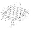
- FIG. 3 is a perspective view explaining the battery case 1.
- FIG. 3 an arrow representing the vehicle front direction F and the vehicle rear direction R, an arrow representing the vehicle width direction W, and an arrow representing the vehicle vertical direction Z are described.
- the vehicle front-rear direction, the vehicle width direction, and the vehicle up-down direction may be expressed as the front-rear direction FR, the width direction W, and the up-down direction Z, respectively.
- the battery case 1 has side frames 10 , cross members 20 , front frames 30 , rear frames 40 and a bottom plate 50 .
- a pair of side frames 10 are provided at a predetermined interval in the vehicle width direction W, and constitute left and right side walls of the battery case 1 . Further, the side frames 10 extend along the front-rear direction FR of the vehicle 100 .
- the front frame 30 forms a front wall in the vehicle front-rear direction FR
- the rear frame 40 forms a rear wall in the vehicle front-rear direction FR.
- the bottom plate 50 constitutes a case bottom surface that functions as a mounting surface of the battery in the battery case 1 .
- the side frames 10, the front frame 30, and the rear frame 40 are erected against the periphery of the bottom plate 50 and welded together to form a box-shaped housing.
- An internal space formed by the side frames 10 , the front frame 30 and the rear frame 40 is partitioned by a plurality of cross members 20 .
- the cross member 20 partitions the internal space of the battery case 1 in the front-rear direction FR, and extends from one side frame 10 to the other side frame 10 .
- the battery case 1 has four cross members 20 .
- each of the plurality of compartments formed by the cross member 20 accommodates a battery.
- a plurality of battery modules constitute one battery (battery pack).
- the battery case 1 is covered with a case cover (not shown) in a state in which a battery module made up of a lithium ion battery or the like is accommodated in an internal space.
- the battery case 1 housing the battery includes the side bracket 60 and the rear side bracket 60R on the outside of the side frame 10 in the vehicle width direction, and is attached to the vehicle body of the vehicle 100 by the side bracket 60 and the rear side bracket 60R. .
- the battery case 1 is formed by maximally utilizing the floor area of the vehicle 100, as shown in FIG. Therefore, in the width direction W of the vehicle 100, the space between the battery case 1 and the vehicle body of the vehicle 100 becomes narrow. Therefore, the battery case 1 is required to have sufficient durability against impacts that may be applied to the vehicle 100, particularly against loads that are applied to the vehicle 100 due to a side collision or the like.
- FIG. 4 is a cross-sectional view taken along line IV-IV in FIG.
- the side brackets 60 are fixed to the outer side surfaces 10S of the side frames 10 forming the left and right walls of the internal space of the battery case 1 by welding or the like.
- the side frame 10 is a hollow plate-like member and has a frame rib 11 extending in the width direction W inside the side frame 10 .
- the side frame 10 has four frame ribs 11, 12, 13, and 14 that partition the interior of the side frame 10 in the vertical direction Z. As shown in FIG.
- the strength of the side frame 10 in the width direction W is increased by frame ribs 11 , 12 , 13 , 14 extending in the width direction W inside the side frame 10 .
- the side bracket 60 includes a body portion 61 for attaching the battery case 1 to the vehicle body, a contact portion 62 that forms one surface of the body portion 61 on the side frame 10 side and contacts the outer surface 10S of the side frame 10, and a contact portion 62 that contacts the outer surface 10S of the side frame 10.
- a support portion 63 protrudes from the lower end 62d of the contact portion 62 and supports the battery case 1 from below.
- the contact portion 62 is fixed to the outer surface 10S and the support portion 63 is fixed to the bottom plate 50 of the battery case 1 by welding or the like.
- the body portion 61 has a protruding end portion 64 that protrudes from the contact portion 62 to the outside of the vehicle in the width direction W of the battery case 1 .
- a hole 64h is formed through the projecting end 64 in the vertical direction Z, and the side bracket 60 and the vehicle 100 are fixed by a bolt passing through the hole 64h.
- the side bracket 60 is a hollow rod-shaped member and has bracket ribs 65 extending in the width direction W inside the side bracket 60 .
- the strength in the width direction W of the side bracket 60 is increased by the bracket ribs 65 extending in the width direction W inside the side bracket 60 .
- the rear side bracket 60R will be described together with the description of the second embodiment of the side bracket 60.
- the cross member 20 is a hollow plate-like member and has member ribs 21 extending in the width direction W inside the cross member 20 .
- the cross member 20 has four member ribs 21, 22, 23, 24 that partition the interior of the cross member 20 in the vertical direction Z. As shown in FIG. Thus, the cross member 20 has increased strength in the width direction W by the member ribs 21 , 22 , 23 , 24 extending in the width direction W inside the cross member 20 .
- the end portion 65e of the bracket rib 65 on the side frame 10 side and the end portion 14b of the frame rib 14 on the side bracket 60 side are arranged to correspond in the vertical direction Z. are placed. That is, the height position in the vertical direction Z of the end portion 65e of the bracket rib 65 on the side frame 10 side and the height position in the vertical direction Z of the end portion 14b on the side bracket 60 side of the frame rib 14 are substantially the same. is configured as
- a load transmission path a load transmission path
- the end portion 11a of the frame rib 11 on the side of the cross member 20 and the end portion 21e of the member rib 21 on the side of the side frame 10 are arranged so as to correspond in the vertical direction Z of the vehicle. That is, the height position in the vertical direction Z of the end portion 11a of the frame rib 11 on the side of the cross member 20 and the height position in the vertical direction Z of the end portion 21e on the side frame 10 side of the member rib 21 are substantially the same. is configured to
- the end portion 12a of the frame rib 12 on the side of the cross member 20 and the end portion 22e of the member rib 22 on the side of the side frame 10 are arranged to correspond in the vertical direction Z of the vehicle. That is, the height position in the vertical direction Z of the end portion 12a of the frame rib 12 on the side of the cross member 20 and the height position in the vertical direction Z of the end portion 22e on the side frame 10 side of the member rib 22 are substantially the same. is configured to
- the height in the vertical direction Z of the ends 13a, 14a of the frame ribs 13, 14 on the side of the cross member 20 and the height in the vertical direction Z of the ends 23e, 24e of the member ribs 23, 24 on the side of the side frame 10 It is arranged so that the height position is the same as the height position.
- a load path is formed that transmits the load input to the frame ribs 11, 12, 13, and 14 of the side frame 10 to the member ribs 21, 22, 23, and 24 of the cross member 20.
- the side bracket 60 includes a main body upper surface portion 67 extending from the protruding end portion 64 to the upper end 62u of the contact portion 62, and a main body lower surface portion extending from the protruding end portion 64 to the lower end 62d of the contact portion 62. a portion 68;
- the cross-sectional shape in the vertical direction Z along the width direction W has a shape that spreads in the vertical direction Z from the projecting end portion 64 toward the vehicle inner side in the width direction W and continues to the contact portion 62 .
- the side bracket 60 is arranged such that the upper end 62u of the contact portion 62 and the end 13b of the frame rib 13 on the side bracket 60 side correspond in the vertical direction Z. That is, the height position of the upper end 62u of the contact portion 62 in the vertical direction Z and the height position of the frame rib 13 in the vertical direction Z are substantially the same.
- the side bracket 60 has passages 66 extending in the front-rear direction FR by partitioning the inside of the side bracket 60 with bracket ribs 65 .
- the passage 66 is a refrigerant passage through which a refrigerant that cools an in-vehicle device such as a rear wheel motor provided in the vehicle 100 passes.
- the pair of side frames 10 extend in the width direction W along the front-rear direction FR so that the battery case 1 has a shape corresponding to the mounting position of the battery case 1 in the vehicle 100. are partially curved so that the distance between them gradually narrows.
- the curved portion 10C is so-called seamlessly formed by bending in multiple steps.
- the battery case 1 includes a pair of side frames 10 forming left and right side walls in the vehicle width direction W, a cross member 20 extending from one side frame 10 to the other side frame 10, and side A side bracket 60 is fixed to the outer side surface 10S of the frame 10 and used to mount the battery case 1 to the vehicle body.
- a pair of side frames 10 forming left and right side walls in the vehicle width direction W are supported in the vehicle width direction W by cross members 20 .
- the side frame 10 has frame ribs 11 , 12 , 13 , 14 extending in the vehicle width direction W within the side frame 10 .
- the side frame 10 is supported in the vehicle width direction W by frame ribs 11 , 12 , 13 and 14 inside the side frame 10 .
- the side bracket 60 has a bracket rib 65 extending in the vehicle width direction W within the side bracket 60 .
- the side bracket 60 is supported in the vehicle width direction W by bracket ribs 65 inside the side bracket 60 .
- the side frames 10 and the side brackets 60 have increased strength in the vehicle width direction W by the frame ribs 11, 12, 13, 14 and the bracket ribs 65. 20 are supported in the width direction W of the vehicle. Therefore, since the strength of the battery case 1 is increased when a load is applied in the vehicle width direction W, the durability against a collision from the side of the vehicle 100, for example, can be improved.
- the battery case 1 is arranged such that the end 65e of the bracket rib 65 on the side frame 10 side and the end 14b of the frame rib 14 on the side bracket 60 side correspond in the vertical direction Z of the vehicle. This forms a load path from the bracket rib 65 through the frame rib 14 . Therefore, the load input to the side bracket 60 from the outside in the vehicle width direction W can be more reliably distributed from the side bracket 60 to the side frame 10 .
- the height position of the frame rib 14 and the height position of the bracket rib 65 in the vehicle vertical direction Z are aligned, so that the rigidity of the battery case 1 in the vehicle width direction W is increased.
- the load input from the side of the vehicle 100 can be smoothly transmitted in the vehicle width direction W of the battery case 1 .
- the cross member 20 has member ribs 21 , 22 , 23 , 24 extending in the vehicle width direction W within the cross member 20 .
- the cross member 20 is supported in the vehicle width direction W by the member ribs 21, 22, 23, and 24 inside the cross member 20, so that the strength of the cross member 20 in the vehicle width direction W can be improved. can.
- the height positions of the ends 11a, 12a, 13a, and 14a of the frame ribs 11, 12, 13, and 14 on the side of the cross member 20 in the vertical direction Z of the vehicle and the member ribs 21, 22, 23, and 24 are aligned with the height positions of the ends 21e, 22e, 23e, and 24e on the side frame 10 side.
- the height position of the frame rib 14 and the height position of the bracket rib 65 in the vehicle vertical direction Z are aligned.
- the rigidity of the battery case 1 in the vehicle width direction W is increased, and the load input from the side of the vehicle 100 can be smoothly transmitted to the battery case 1 in the vehicle width direction W.
- the side bracket 60 includes a contact portion 62 that contacts the outer surface 10S of the side frame 10, and a support portion 63 that supports the bottom of the battery case 1 from below. That is, the battery case 1 is held by the side brackets 60 and supported by the vehicle body. Therefore, even if an excessive load is applied to the side surface of the vehicle 100, the joint between the side bracket 60 and the battery case 1 is broken and the battery case 1 can be prevented from falling off from the vehicle body.
- the upper end 62u of the contact portion 62 and the end 13b of the frame rib 13 on the side bracket 60 side are arranged to correspond in the vertical direction Z of the vehicle. Therefore, a load path extending from the contact portion 62 of the side bracket 60 to the frame rib 13 is formed. As a result, the load input from the side bracket 60 can be distributed to the side frames 10 more reliably.
- the side bracket 60 is provided with a passage 66 extending in the vehicle front-rear direction FR by partitioning the inside of the side bracket 60 with the bracket rib 65 .
- This passage 66 is a refrigerant passage for cooling the vehicle-mounted device. Therefore, there is no need to separately form a coolant passage, and the layout of the vehicle 100 can be improved. Moreover, since the coolant passage can be formed inside the side bracket 60, the passage 66 as the coolant passage can be protected from the load from the outside.
- the pair of side frames 10 has curved portions 10C that are curved such that the distance between them in the width direction W gradually narrows along the front-rear direction FR.
- the curved portion 10C is formed by seamless processing and has no welded portion. Therefore, the rigidity of the side frame 10 can be increased as compared with the case where the side frame 10 is configured by combining linear members.
- the battery case 1 As described above, according to the battery case 1 described above, it is possible to improve the durability against the load applied to the side surface of the vehicle 100, and it is possible to more reliably protect the contained battery.
- FIG. 5 is a cross-sectional view illustrating the battery case 1 according to the second embodiment of the invention, cut at the same position as the battery case 1 according to the first embodiment shown in FIG.
- the battery case 1 shown as the second embodiment differs from the battery case 1 shown as the first embodiment in the structure of the side bracket 60 .
- components having the same functions as those described in the battery case 1 are denoted by the same reference numerals, and detailed description thereof will be omitted.
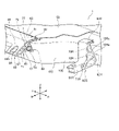
- FIG. 6 is a perspective view of the main part of the battery case 1 of FIG. 5 as seen from the bottom side of the vehicle 100.
- FIG. 6 a stepped portion 51 is formed along the front-rear direction FR of the vehicle 100 on the lower surface of the bottom plate 50 forming the bottom portion of the battery case 1 .
- the lower end surface of the support portion 63 is formed to protrude to one side and has a facing portion 80 that faces the stepped portion 51 positioned on the vehicle outer side in the width direction W.
- the stepped portion 51 and the facing portion 80 are arranged so as to face each other, and the bottom plate 50 forming the lower surface of the support portion 63 in the main body portion 61 and the bottom portion of the battery case 1 . is flat in the vertical direction Z of the vehicle, forming a flush structure.
- the side bracket 60 includes a first rib 71, a second rib 72, a third rib 73, a fourth rib 74, and a fifth rib extending in the width direction W or the vertical direction Z inside the side bracket 60. It has a rib 75 , a sixth rib 76 and a seventh rib 77 .
- the first rib 71 has one end connected to the main body upper surface portion 67 , extends along the vertical direction Z, and the other end connected to the main body lower surface portion 68 . Also, the first rib 71 extends in the front-rear direction FR.
- the second rib 72 has one end connected to the vicinity of the central portion 71c in the up-down direction Z of the first rib 71 and extends in the width direction W and the front-rear direction FR.
- the third rib 73 has one end connected to the inner side in the width direction W of the connecting portion between the main body lower surface portion 68 and the first rib 71, and extends in the width direction W and the front-rear direction FR.
- the fourth rib 74 has one end connected to the inner side in the width direction W of the connecting portion between the main body upper surface portion 67 and the first rib 71, and extends in the up-down direction Z and the front-rear direction FR.
- the other end of the second rib 72 , the other end of the third rib 73 , and the other end of the fourth rib 74 are gathered and connected near the center inside the side bracket 60 to form a first gathering portion 78 .
- the fifth rib 75 has one end connected to the main body upper surface portion 67 and extends in the width direction W and the front-rear direction FR.
- the sixth rib 76 has one end connected to the first collective portion 78 and extends in the width direction W and the front-rear direction FR.
- the other end of the fifth rib 75 and the other end of the sixth rib 76 are aggregated and connected at the contact portion 62 to form a second aggregate portion 79 .
- the seventh rib 77 extends from the first collective portion 78 in a direction different from the sixth rib 76 in the width direction W and is connected to the contact portion 62 .
- the strength of the side bracket 60 in the vehicle width direction W and the vertical direction Z is increased.
- the side bracket 60 is formed with the following load path as an example. That is, a first load path is formed through which the load input from the projecting end 64 passes through the main body upper surface 67 , the first rib 71 , the second rib 72 and the seventh rib 77 and connects to the side frame 10 . Further, a second load path that passes the load input from the projecting end 64 to the side frame 10 through the main body lower surface portion 68, the third rib 73, the first aggregated portion 78, the sixth rib 76, and the second aggregated portion 79 is provided. It is formed.
- a second load path is formed through which the load input from the projecting end 64 passes through the main body upper surface 67, the fourth rib 74, the first converging portion 78, and the sixth rib 76 and connects to the side frame 10.
- a third load path is formed through which the load input from the projecting end portion 64 is connected to the side frame 10 from the main body upper surface portion 67 , the fifth rib 75 and the second aggregated portion 79 .
- a fourth load path is formed through which the load input from the projecting end portion 64 passes through the main body upper surface portion 67, the fourth rib 74, the first consolidating portion 78, the seventh rib 77, and the support portion 63 and connects to the bottom plate 50. .
- the fourth rib 74, the fifth rib 75, and the sixth rib 56 are formed so that the cross-sectional shape in the vertical direction Z along the width direction W is circular. That is, in the side bracket 60, the fourth rib 74, the fifth rib 75, and the sixth rib 56 form a cylindrical passage Sw extending in the front-rear direction FR. Cylindrical passage Sw is a passage for conveying a coolant for cooling an in-vehicle device provided in vehicle 100 .
- the side bracket 60 is provided with the first rib 71 to the seventh rib 77 described above, so that the inside of the side bracket 60 has a cross section in the vertical direction Z along the width direction W in which the cylindrical passage Sw, the space Sa, It is divided into Sb, Sc, Sd and Se.
- the spaces Sa, Sb, Sc, Sd, and Se are crushed by deformation or breakage of the first rib 71 to the fifth rib 75 when an excessive load is applied to the side bracket 60 . That is, it functions as a buffer structure for absorbing the load transmitted to the side frame 10 .
- the rear side bracket 60R includes a body portion 61R for attaching the battery case 1 to the vehicle body, a contact portion 62R that forms one surface of the body portion 61R on the side frame 10 side and contacts the outer surface 10S of the side frame 10, and a contact portion 62R.
- a support portion 63R protrudes from the lower end of the contact portion 62R and supports the battery case 1 from below.
- a first rib 71R, a second rib 72R, and a third rib 73R are provided inside the rear side bracket 60R.
- the first rib 71R extends in the front-rear direction FR along the up-down direction Z.
- the second rib 72R and the third rib 73R are arranged so as to partition the interior of the rear side bracket 60R in the vertical direction Z. As shown in FIG.
- the side frame 10 side end portions 72Re and 73Re of the second rib 72R and the third rib 73R extending in the width direction W are arranged inside the side frame 10.
- the frame ribs 11, 12, 13, 14, etc. are arranged so as to correspond to the ends of the frame ribs 11, 12, 13, 14, etc. on the side of the rear side bracket 60R.
- a load path is formed such that the load input to the rear side bracket 60R is transmitted to the side frame 10.
- the rear side bracket 60R has a second rib 72R and a third rib 73R extending in the vehicle width direction W within the rear side bracket 60R.
- the rear side bracket 60R is supported in the vehicle width direction W inside the rear side bracket 60R by the second rib 72R and the third rib 73R. Therefore, the strength of the rear side bracket 60R in the vehicle width direction W is enhanced.
- the height positions of the end portions 72Re and 73Re of the second rib 72R and the third rib 73R of the rear side bracket 60R on the side frame 10 side and the frame rib 11 arranged inside the side frame 10 , 12, 13, 14, etc. are aligned with the height positions of the ends on the rear side bracket 60R side.
- the height positions of the end portions 72Re and 73Re of the second rib 72R and the third rib 73R of the rear side bracket 60R on the side frame 10 side and the frame rib 11 arranged inside the side frame 10 , 12, 13, and 14 are aligned with the height positions of the ends of the rear side bracket 60R side, the rigidity of the battery case 1 in the vehicle width direction W is enhanced even on the rear side of the vehicle 100, and the vehicle 100 can be smoothly transmitted in the vehicle width direction W of the battery case 1 .
- the side bracket 60 has a first rib 71, a second rib 72, a third rib 73, a fourth rib 74, a fifth rib 75, and a sixth rib extending in the width direction W or the vertical direction Z.
- a rib 76 and a seventh rib 77 are formed.
- load paths such as the first load path to the fourth load path are formed in the side bracket 60 as an example. Therefore, the load input from the projecting end portion 64 of the side bracket 60 can be distributed to the side frame 10 more reliably.
- the height position of the second aggregated portion 79 of the side bracket 60 and the height position of the end portion 14b of the frame rib 14 of the side frame 10 on the side bracket 60 side are aligned. there is Due to the load path thus formed, the load input from the side of the vehicle 100 can be smoothly transmitted in the vehicle width direction W of the battery case 1 .
- spaces Sa, Sb, Sc, Sd, and Se functioning as a buffer structure are formed inside the side bracket 60 by the first rib 71 to the seventh rib 77 provided. It is In such a structure, when an excessive load is input to the side bracket 60, the spaces Sa, Sb, Sc, Sd, and Se are crushed, thereby absorbing the excessive load input from the side of the vehicle 100. can be absorbed. Therefore, it is possible to prevent excessive load from being transmitted to the side frames 10 .
- a cylindrical passage Sw is formed inside the side bracket 60 .
- the passage is cylindrical in this way, stress is less likely to concentrate, and the strength of the passage itself is increased. Furthermore, it also contributes to the strength improvement of the side bracket 60 as a whole.
- the battery case 1 As described above, according to the battery case 1 described above, it is possible to improve the durability against the load applied to the side surface of the vehicle 100, and it is possible to more reliably protect the contained battery.
- the curved portion 10C formed in the side frame 10 is not limited to one location. It can be changed as appropriate according to the design of the battery case 1 . A plurality of curved portions may be formed on the side frame 10 .
- the cross-sectional shapes of the side frames 10 and the cross member 20 are not limited to the shapes shown in FIGS. 4 and 6.
- the position of the cylindrical passage Sw in the side bracket 60 is not limited to the position shown in FIG. Alternatively, any one of the spaces Sa, Sb, Sc, Sd and Se formed by dividing the inside of the side bracket 60 by the first rib 71 or the seventh rib 77 may be used as the refrigerant passage.
- the load path formed within the side bracket 60 by providing the first rib 71 to the seventh rib 77 is not limited to the first load path to the fourth load path described above.
Landscapes
- Engineering & Computer Science (AREA)
- Chemical & Material Sciences (AREA)
- Transportation (AREA)
- Mechanical Engineering (AREA)
- Chemical Kinetics & Catalysis (AREA)
- Electrochemistry (AREA)
- General Chemical & Material Sciences (AREA)
- Combustion & Propulsion (AREA)
- Sustainable Energy (AREA)
- Power Engineering (AREA)
- Sustainable Development (AREA)
- Life Sciences & Earth Sciences (AREA)
- Aviation & Aerospace Engineering (AREA)
- Arrangement Or Mounting Of Propulsion Units For Vehicles (AREA)
- Secondary Cells (AREA)
- Battery Mounting, Suspending (AREA)
- Body Structure For Vehicles (AREA)
Priority Applications (5)
| Application Number | Priority Date | Filing Date | Title |
|---|---|---|---|
| US18/563,641 US12496891B2 (en) | 2021-05-27 | 2021-05-27 | Battery case |
| CN202180098697.9A CN117396350A (zh) | 2021-05-27 | 2021-05-27 | 电池外壳 |
| EP21942150.0A EP4349627B1 (en) | 2021-05-27 | 2021-05-27 | Battery case |
| PCT/JP2021/020275 WO2022249409A1 (ja) | 2021-05-27 | 2021-05-27 | バッテリケース |
| JP2023523875A JP7563592B2 (ja) | 2021-05-27 | 2021-05-27 | バッテリケース |
Applications Claiming Priority (1)
| Application Number | Priority Date | Filing Date | Title |
|---|---|---|---|
| PCT/JP2021/020275 WO2022249409A1 (ja) | 2021-05-27 | 2021-05-27 | バッテリケース |
Publications (1)
| Publication Number | Publication Date |
|---|---|
| WO2022249409A1 true WO2022249409A1 (ja) | 2022-12-01 |
Family
ID=84228687
Family Applications (1)
| Application Number | Title | Priority Date | Filing Date |
|---|---|---|---|
| PCT/JP2021/020275 Ceased WO2022249409A1 (ja) | 2021-05-27 | 2021-05-27 | バッテリケース |
Country Status (5)
| Country | Link |
|---|---|
| US (1) | US12496891B2 (enExample) |
| EP (1) | EP4349627B1 (enExample) |
| JP (1) | JP7563592B2 (enExample) |
| CN (1) | CN117396350A (enExample) |
| WO (1) | WO2022249409A1 (enExample) |
Cited By (1)
| Publication number | Priority date | Publication date | Assignee | Title |
|---|---|---|---|---|
| WO2025187369A1 (ja) * | 2024-03-05 | 2025-09-12 | 三菱自動車工業株式会社 | 電池パックのトレイ及びこのトレイを備える電池パック |
Families Citing this family (1)
| Publication number | Priority date | Publication date | Assignee | Title |
|---|---|---|---|---|
| KR20240015824A (ko) * | 2022-07-27 | 2024-02-06 | 현대자동차주식회사 | 차량용 배터리 모듈 마운팅 어셈블리 |
Citations (6)
| Publication number | Priority date | Publication date | Assignee | Title |
|---|---|---|---|---|
| JPH09109692A (ja) * | 1995-10-20 | 1997-04-28 | Nissan Motor Co Ltd | 電気自動車 |
| JP2936959B2 (ja) | 1993-06-04 | 1999-08-23 | 日産自動車株式会社 | 電気自動車のフロア構造 |
| JP2013103599A (ja) * | 2011-11-14 | 2013-05-30 | Honda Motor Co Ltd | 電動車両用バッテリパック |
| US20130192913A1 (en) * | 2010-04-28 | 2013-08-01 | Compagnie Generale Des Etablissements Michelin | Battery Box for Electric or Hybrid Vehicle and Method for Mounting Said Box on the Vehicle |
| JP2021046010A (ja) * | 2019-09-17 | 2021-03-25 | トヨタ自動車株式会社 | 燃料電池スタックの車両搭載構造及び車両搭載方法 |
| WO2021070288A1 (ja) * | 2019-10-09 | 2021-04-15 | 日産自動車株式会社 | 自動車 |
Family Cites Families (13)
| Publication number | Priority date | Publication date | Assignee | Title |
|---|---|---|---|---|
| US4365681A (en) * | 1980-12-22 | 1982-12-28 | General Motors Corporation | Battery support structure |
| JP4306783B2 (ja) * | 2007-12-14 | 2009-08-05 | 三菱自動車工業株式会社 | 電気自動車のバッテリユニット取付構造 |
| JP5013140B2 (ja) * | 2009-12-10 | 2012-08-29 | 三菱自動車工業株式会社 | バッテリーケース |
| JP5408441B2 (ja) * | 2010-01-18 | 2014-02-05 | 三菱自動車工業株式会社 | 車両用バッテリケース |
| JP5408440B2 (ja) * | 2010-01-18 | 2014-02-05 | 三菱自動車工業株式会社 | 車両用バッテリケース |
| JP5403290B2 (ja) * | 2011-03-31 | 2014-01-29 | 三菱自動車工業株式会社 | 電気自動車のバッテリ搭載構造 |
| KR101315741B1 (ko) * | 2012-03-23 | 2013-10-10 | 현대자동차주식회사 | 치수안정성이 우수한 전기자동차용 배터리 팩 케이스 어셈블리와 그 제조 방법 |
| JP5846193B2 (ja) * | 2013-12-25 | 2016-01-20 | トヨタ自動車株式会社 | 車両用電池搭載構造 |
| CN104443039B (zh) * | 2014-11-19 | 2016-04-20 | 湖南大学 | 一种用于电池包分布式安装的电动汽车车架结构 |
| CN104859717B (zh) * | 2015-04-13 | 2017-07-11 | 中航爱维客汽车有限公司 | 电动轻型客车车架结构及电动轻型客车 |
| FR3054817B1 (fr) * | 2016-08-02 | 2018-08-24 | Peugeot Citroen Automobiles Sa | Element de renfort modulable pour caisse de vehicule automobile pour la protection en cas de choc arriere ou de choc lateral |
| JP6514248B2 (ja) * | 2017-02-17 | 2019-05-15 | 本田技研工業株式会社 | 車体の下部構造 |
| CN114502401B (zh) * | 2019-07-01 | 2025-03-07 | Sabic环球技术有限责任公司 | 用于车辆电池包框架的混合能量吸收 |
-
2021
- 2021-05-27 WO PCT/JP2021/020275 patent/WO2022249409A1/ja not_active Ceased
- 2021-05-27 CN CN202180098697.9A patent/CN117396350A/zh active Pending
- 2021-05-27 JP JP2023523875A patent/JP7563592B2/ja active Active
- 2021-05-27 EP EP21942150.0A patent/EP4349627B1/en active Active
- 2021-05-27 US US18/563,641 patent/US12496891B2/en active Active
Patent Citations (6)
| Publication number | Priority date | Publication date | Assignee | Title |
|---|---|---|---|---|
| JP2936959B2 (ja) | 1993-06-04 | 1999-08-23 | 日産自動車株式会社 | 電気自動車のフロア構造 |
| JPH09109692A (ja) * | 1995-10-20 | 1997-04-28 | Nissan Motor Co Ltd | 電気自動車 |
| US20130192913A1 (en) * | 2010-04-28 | 2013-08-01 | Compagnie Generale Des Etablissements Michelin | Battery Box for Electric or Hybrid Vehicle and Method for Mounting Said Box on the Vehicle |
| JP2013103599A (ja) * | 2011-11-14 | 2013-05-30 | Honda Motor Co Ltd | 電動車両用バッテリパック |
| JP2021046010A (ja) * | 2019-09-17 | 2021-03-25 | トヨタ自動車株式会社 | 燃料電池スタックの車両搭載構造及び車両搭載方法 |
| WO2021070288A1 (ja) * | 2019-10-09 | 2021-04-15 | 日産自動車株式会社 | 自動車 |
Cited By (1)
| Publication number | Priority date | Publication date | Assignee | Title |
|---|---|---|---|---|
| WO2025187369A1 (ja) * | 2024-03-05 | 2025-09-12 | 三菱自動車工業株式会社 | 電池パックのトレイ及びこのトレイを備える電池パック |
Also Published As
| Publication number | Publication date |
|---|---|
| JPWO2022249409A1 (enExample) | 2022-12-01 |
| CN117396350A (zh) | 2024-01-12 |
| JP7563592B2 (ja) | 2024-10-08 |
| US20240286477A1 (en) | 2024-08-29 |
| US12496891B2 (en) | 2025-12-16 |
| EP4349627B1 (en) | 2025-08-20 |
| EP4349627A1 (en) | 2024-04-10 |
| EP4349627A4 (en) | 2024-10-30 |
Similar Documents
| Publication | Publication Date | Title |
|---|---|---|
| CN110352157B (zh) | 车辆的下部车身结构 | |
| CN109263455B (zh) | 车身前部结构 | |
| US9505295B2 (en) | Structure for front section of vehicle body | |
| US8813888B2 (en) | Vehicle body rear structure | |
| JP6506327B2 (ja) | 電気自動車のフロア構造 | |
| CN114728570B (zh) | 车辆用电池包的支承装置及电动车辆 | |
| EP4063239B1 (en) | Vehicle with a battery pack support device | |
| US6830289B2 (en) | Front structure of vehicle | |
| WO2022249409A1 (ja) | バッテリケース | |
| CN114852176A (zh) | 车辆搭载用电池封装体 | |
| KR20190072342A (ko) | 전방 차체 보강구조 | |
| JP2022025814A (ja) | 車両用バッテリパックの支持装置 | |
| JP2012121375A (ja) | 車両のバッテリ配設構造 | |
| US11807095B2 (en) | Lower structure of vehicle having planar protector at inner side surface of battery unit | |
| JP5488506B2 (ja) | 車両の下部車体構造 | |
| JP2021133863A (ja) | 電動車両 | |
| JP3489458B2 (ja) | 自動車の車体構造 | |
| JP2009067113A (ja) | 前部車体構造 | |
| JP6107796B2 (ja) | 自動車の前部構造 | |
| JP7577588B2 (ja) | 車両のボデー構造 | |
| CN121157608A (zh) | 电动车辆 | |
| JP6795414B2 (ja) | 自動車の補助バッテリ配置構造 | |
| JP2024029478A (ja) | 車両のフロア構造 | |
| CN121054941A (zh) | 车辆用蓄电装置 | |
| WO2025203342A1 (ja) | 車両構造 |
Legal Events
| Date | Code | Title | Description |
|---|---|---|---|
| 121 | Ep: the epo has been informed by wipo that ep was designated in this application |
Ref document number: 21942150 Country of ref document: EP Kind code of ref document: A1 |
|
| WWE | Wipo information: entry into national phase |
Ref document number: 2023523875 Country of ref document: JP |
|
| WWE | Wipo information: entry into national phase |
Ref document number: 18563641 Country of ref document: US |
|
| WWE | Wipo information: entry into national phase |
Ref document number: 202180098697.9 Country of ref document: CN |
|
| NENP | Non-entry into the national phase |
Ref country code: DE |
|
| WWE | Wipo information: entry into national phase |
Ref document number: 2021942150 Country of ref document: EP |
|
| ENP | Entry into the national phase |
Ref document number: 2021942150 Country of ref document: EP Effective date: 20240102 |
|
| WWG | Wipo information: grant in national office |
Ref document number: 2021942150 Country of ref document: EP |