WO2022249395A1 - 内燃機関の排気還流制御方法および制御装置 - Google Patents
内燃機関の排気還流制御方法および制御装置 Download PDFInfo
- Publication number
- WO2022249395A1 WO2022249395A1 PCT/JP2021/020185 JP2021020185W WO2022249395A1 WO 2022249395 A1 WO2022249395 A1 WO 2022249395A1 JP 2021020185 W JP2021020185 W JP 2021020185W WO 2022249395 A1 WO2022249395 A1 WO 2022249395A1
- Authority
- WO
- WIPO (PCT)
- Prior art keywords
- exhaust gas
- gas recirculation
- ignition timing
- internal combustion
- combustion engine
- Prior art date
- Legal status (The legal status is an assumption and is not a legal conclusion. Google has not performed a legal analysis and makes no representation as to the accuracy of the status listed.)
- Ceased
Links
Images

Classifications
-
- F—MECHANICAL ENGINEERING; LIGHTING; HEATING; WEAPONS; BLASTING
- F02—COMBUSTION ENGINES; HOT-GAS OR COMBUSTION-PRODUCT ENGINE PLANTS
- F02D—CONTROLLING COMBUSTION ENGINES
- F02D21/00—Controlling engines characterised by their being supplied with non-airborne oxygen or other non-fuel gas
- F02D21/06—Controlling engines characterised by their being supplied with non-airborne oxygen or other non-fuel gas peculiar to engines having other non-fuel gas added to combustion air
- F02D21/08—Controlling engines characterised by their being supplied with non-airborne oxygen or other non-fuel gas peculiar to engines having other non-fuel gas added to combustion air the other gas being the exhaust gas of engine
-
- Y—GENERAL TAGGING OF NEW TECHNOLOGICAL DEVELOPMENTS; GENERAL TAGGING OF CROSS-SECTIONAL TECHNOLOGIES SPANNING OVER SEVERAL SECTIONS OF THE IPC; TECHNICAL SUBJECTS COVERED BY FORMER USPC CROSS-REFERENCE ART COLLECTIONS [XRACs] AND DIGESTS
- Y02—TECHNOLOGIES OR APPLICATIONS FOR MITIGATION OR ADAPTATION AGAINST CLIMATE CHANGE
- Y02T—CLIMATE CHANGE MITIGATION TECHNOLOGIES RELATED TO TRANSPORTATION
- Y02T10/00—Road transport of goods or passengers
- Y02T10/10—Internal combustion engine [ICE] based vehicles
- Y02T10/40—Engine management systems
Definitions
- the present invention relates to exhaust gas recirculation control for an internal combustion engine, and more particularly to exhaust gas recirculation control that determines an appropriate target exhaust gas recirculation rate based on detection of combustion fluctuations.
- Exhaust gas recirculation also abbreviated as EGR
- EGR rate exhaust gas recirculation rate
- Patent Document 1 an ion current is detected via a spark plug while increasing or decreasing the EGR rate, and when an ion current generated during an exhaust stroke due to destabilization of combustion is detected, the EGR rate is immediately before a misfire. is the limit exhaust gas recirculation rate.
- the ignition timing is set to a sampling ignition timing retarded from the basic ignition timing in order to determine the target exhaust gas recirculation rate.
- the target exhaust gas recirculation rate is determined.
- the limit target exhaust gas recirculation rate can be obtained without being affected by the misfire cycle.
- FIG. 1 is a configuration explanatory diagram showing the system configuration of an internal combustion engine to which the present invention is applied; Explanatory drawing which showed the operation
- FIG. 1 shows the system configuration of an automotive internal combustion engine 1 to which the present invention is applied.
- the internal combustion engine 1 is, for example, a four-stroke cycle spark ignition internal combustion engine equipped with a turbocharger 2.
- a pair of intake valves 4 and a pair of exhaust valves 5 are arranged on the ceiling wall surface of each cylinder 3.
- an ignition plug 6 is arranged in a central portion surrounded by these intake valves 4 and exhaust valves 5 .
- a fuel injection valve 7 for supplying fuel into the cylinder 3 is provided below the intake valve 4 .
- An engine controller 9 controls the ignition timing of the ignition plug 6 and the injection timing and injection amount of fuel by the fuel injection valve 7 .
- a washer-like in-cylinder pressure sensor 8 is provided on the seat where the spark plug 6 is attached to detect the in-cylinder pressure.
- an in-cylinder pressure sensor whose detection portion faces the combustion chamber 10 may be used.
- An intake passage 11 connected to the combustion chamber 10 via the intake valve 4 has an intake collector 11a.
- a controlled throttle valve 12 is provided.
- a compressor 2a of the turbocharger 2 is positioned upstream of the throttle valve 12, and an airflow meter 14 and an air cleaner 15 for detecting the amount of intake air are disposed upstream of the compressor 2a.
- a water-cooled intercooler 16 is provided between the compressor 2a and the throttle valve 12, for example.
- a recirculation valve 17 is provided to communicate the discharge side and the suction side of the compressor 2a. This recirculation valve 17 is opened during deceleration when the throttle valve 12 is closed.
- a turbine 2b of the turbocharger 2 is interposed in an exhaust passage 20 connected to the combustion chamber 10 via an exhaust valve 5, and a pre-catalyst device 21 and a main catalyst device each comprising a three-way catalyst are provided downstream thereof. 22 are provided.
- An air-fuel ratio sensor 23 that detects the air-fuel ratio is arranged upstream of the turbine 2b in the exhaust passage 20.
- the turbine 2b is equipped with a wastegate valve 24 that bypasses part of the exhaust depending on the boost pressure in order to control the boost pressure.
- the waste gate valve 24 is, for example, of an electric type whose opening is controlled by the engine controller 9 .
- an exhaust gas recirculation passage 25 for recirculating part of the exhaust gas from the exhaust passage 20 to the intake passage 11 is provided.
- one end of the exhaust gas recirculation passage 25 is connected between the pre-catalyst device 21 and the main catalyst device 22 of the exhaust passage 20, and the other end of the exhaust gas recirculation passage 25 is connected to a position upstream of the compressor 2a of the intake passage 11.
- the exhaust gas recirculation passage 25 includes, for example, a water-cooled EGR gas cooler 27 that cools the recirculated exhaust gas, and an EGR valve 28 that controls the exhaust gas recirculation amount. The opening of the EGR valve 28 is controlled by the engine controller 9 .
- the engine controller 9 includes the in-cylinder pressure sensor 8, the airflow meter 14, the air-fuel ratio sensor 23, a crank angle sensor 31 for detecting the engine rotation speed, a water temperature sensor 32 for detecting the cooling water temperature, An accelerator opening sensor 33 that detects the amount of depression of the accelerator pedal to be operated, a vehicle speed sensor 34 that directly or indirectly detects the vehicle speed, an atmospheric pressure sensor 35 that detects the atmospheric pressure, an outside temperature sensor 36 that detects the outside temperature, an excess Detection signals from sensors such as the supercharging pressure sensor 37 for detecting the boost pressure are input. Based on these detection signals, the engine controller 9 optimizes the fuel injection amount, injection timing, ignition timing, opening of the throttle valve 12, opening of the EGR valve 28 (in other words, EGR rate), boost pressure, etc. controlled to
- the engine controller 9 processes the detection signal of the in-cylinder pressure sensor 8 to calculate the indicated mean effective pressure fluctuation rate CPi (hereinafter simply referred to as the fluctuation rate CPi), which is an index indicating the combustion fluctuation. Then, as will be described later, at the beginning of exhaust gas recirculation, a target EGR rate set for each engine operating condition (load and rotational speed) is searched for or determined using the fluctuation rate CPi.
- the target EGR rate is the highest EGR rate within a range that does not cause excessive destabilization of combustion.
- the exhaust gas recirculation amount (the opening of the EGR valve 28) is controlled along with this target EGR rate.
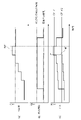
- FIG. 2 is an explanatory diagram for explaining the principle of the present invention, showing (a) EGR rate, (b) ignition timing, and (c) fluctuation rate CPi in comparison.
- the horizontal axis represents time, and shows changes in the fluctuation rate CPi when the EGR rate is increased stepwise as shown in column (a) in order to search for the target EGR rate, which is the limit of combustion stability. ing.
- dashed lines in columns (b) and (c) indicate a comparative example, in which the ignition timing is maintained at the basic ignition timing (eg MBT).
- the fluctuation rate CPi gradually increases as the EGR rate increases.
- this misfire MF occurs suddenly due to cycle variation or the like, it becomes a factor that makes evaluation of combustion fluctuation difficult.
- a misfire MF occurs before threshold CPi#2, which is the permissible limit of combustion fluctuation, is reached, and determination based on threshold CPi#2 becomes impossible.
- the sampling ignition timing retarded by a predetermined amount from the basic ignition timing is used for searching for the target EGR rate. Then, the EGR rate is gradually increased, and the EGR rate when the variation rate CPi reaches a predetermined threshold value CPi#, for example, is set as the limit EGR rate, that is, the target EGR rate.
- the retard amount of the sampling ignition timing may be set to, for example, about 5 to 15° CA, and an example is 10° CA. This retard amount may be a constant value regardless of the operating conditions, or it may be set according to the rotation speed so that the higher the rotation speed, the smaller the value, taking into consideration changes in real time. can be
- the fluctuation rate CPi increases as a whole, but misfires are less likely to occur, and the fluctuation rate CPi increases as the EGR rate increases. can be grasped without being affected by misfire. Therefore, for example, by appropriately setting the threshold value CPi# of the variation rate CPi under the sampling ignition timing, the variation rate CPi will reach the threshold value CPi#2 under the basic ignition timing. can be searched for.
- the EGR rate shown as EGR1 in column (a) is the target EGR rate.
- the thresholds CPi#2 and CPi# differ depending on the level to which they are permissible.
- the threshold CPi#2 is about 2%, and the threshold CPi# is about 5%, for example. is.
- the threshold CPi# is set in consideration of the retard amount of the sampling ignition timing.
- the amount of change in CPi with respect to the amount of change in the EGR rate (for example, the unit change amount shown in steps in column a) is greater when the ignition timing is on the retard side than when the ignition timing is at the MBT point. It becomes larger at the sampling ignition timing, and in particular at an EGR rate close to the limit EGR rate, the amount of change in the variation rate CPi under the sampling ignition timing becomes remarkably large. Therefore, it is possible to determine that the limit EGR rate is reached when the rate of increase of variation rate CPi when the EGR rate is gradually increased reaches a predetermined magnitude, instead of comparison with threshold value CPi#.
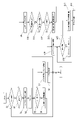
- FIG. 3 is a flow chart showing the flow of processing executed by the engine controller 9, and the routine shown in this flow chart is repeatedly executed, for example, at regular time intervals.
- step 1 it is determined whether or not the operating condition or operating point defined by the load and rotational speed is within a predetermined EGR region in which exhaust gas recirculation should be performed. If it is outside the EGR region, the routine ends. If it is within the EGR region, the process proceeds to step 2, and it is determined whether learning (that is, search or determination) of the target EGR rate has not yet been performed for the operating condition. Since the learning is not performed the first time, the process advances from step 2 to step 3 to set the ignition timing to the sampling ignition timing retarded by a predetermined amount (for example, 10° CA) from the basic ignition timing (MBT in one embodiment).
- a predetermined amount for example, 10° CA
- step 5 the fluctuation rate CPi is compared with a predetermined threshold value (corresponding to the aforementioned threshold value CPi#), and in step 6, the EGR rate at that time is gradually increased by adding a constant amount ⁇ .
- a predetermined threshold value corresponding to the aforementioned threshold value CPi#
- step 6 the EGR rate at that time is gradually increased by adding a constant amount ⁇ .
- the variation rate CPi gradually increases without misfiring and eventually reaches the threshold value. If it is determined in step 5 that the variation rate CPi is equal to or greater than the threshold value, the process proceeds to step 7, and the EGR rate at that time is learned as the target EGR rate.
- step 8 the process proceeds to step 8 to end retarding the ignition timing for searching for the target EGR rate.
- step 8 instead of the comparison with the threshold value in step 5, it is also possible to make a determination based on the rate of increase of the fluctuation rate CPi.
- step 9 exhaust gas recirculation is controlled according to the learned target EGR rate.
- the search or determination of the target EGR rate and the exhaust gas recirculation control using the learned target EGR rate are performed for each engine operating condition (operating point).
- each learned target EGR rate is assigned to a map having load and rotational speed as parameters. Therefore, when the operating condition changes to an unlearned operating condition, the operating condition is newly learned.
- the target EGR rate which is a learned value on the map, is initialized at the start of a vehicle trip.
- step 10 it is determined whether or not it is time to reconfirm the adequacy of the learned value (target EGR rate).
- target EGR rate the cumulative operating time under the same operating conditions reaches a certain time (eg, 5 minutes, etc.). or (3) a misfire is detected, it is determined that reconfirmation of the target EGR rate is necessary.
- the above condition (1) is for reconfirming whether the target EGR rate set in steps 5-7 is appropriate.
- the above condition (2) takes into consideration the fact that the EGR rate, which actually becomes the limit of combustion stability, may change during continuous operation.
- the above condition (3) is for relearning immediately when a misfire occurs under the target EGR rate.
- step 10 in steps 11 to 13, while exhaust gas recirculation is performed in accordance with the target EGR rate, the variation rate CPi is determined to be equal to or greater than the above threshold under ignition timing with a smaller retard amount than the sampling ignition timing. determine whether or not That is, in step 11, the retard amount is compared with a predetermined retard amount (for example, 10° CA) which is the retard amount of the sampling ignition timing. If it is less than the predetermined retard amount, it is determined in step 12 whether the fluctuation rate CPi is less than the threshold value. If YES in step 12, the process proceeds to step 13 to increment the retard amount by a constant amount ⁇ .
- a predetermined retard amount for example, 10° CA
- the fluctuation rate CPi basically increases according to the retard amount.
- the variation rate CPi becomes equal to or higher than the threshold value before the retard amount reaches the predetermined retard amount when the retard amount is increased, the process proceeds from step 12 to step 14 .
- the learned target EGR rate is excessive, and re-learning is performed in steps 14 to 18 in the direction of lowering the target EGR rate. That is, at step 14, the retard amount is again set to the sampling ignition timing, and at step 15, it is determined whether or not the fluctuation rate CPi is less than the threshold value, and at step 16, the EGR rate is decremented by a constant amount ⁇ .
- step 15 the EGR rate is searched for when the fluctuation rate CPi is below the threshold.
- step 15 the process proceeds from step 15 to step 17, the EGR rate at that time is set as the target EGR rate (that is, learned), and in step 18 the ignition timing is returned to the basic ignition timing (eg MBT).
- the processing may be returned from step 14 to step 4 for re-learning.
- step 11 is executed.
- re-learning is performed under a predetermined retard amount, ie, sampling ignition timing.
- the target EGR rate which is the current learned value, is at least not excessively high, but may be too small.
- a search for an appropriate target EGR rate is performed again under the sampling ignition timing. Therefore, in this embodiment, if the operation is continued under the same operating conditions, the target EGR rate is learned and updated at least every fixed time (for example, 5 minutes). It should be noted that the confirmation process from step 11 onward may be performed not necessarily at regular intervals but at appropriate timings.
- the ignition timing may be retarded for searching for the target EGR rate only in some cylinders, for example, only one specific cylinder, and the variation rate CPi may be calculated for that cylinder.
- the other cylinders continue to operate at the basic ignition timing (MBT, for example) during learning and re-learning, thereby minimizing deterioration in fuel consumption caused by retarding the ignition timing.
- the retard amount of the sampling ignition timing may be set according to the rotation speed so that the higher the rotation speed, the smaller the value.
- CPi is affected by the retard amount. Therefore, the optimal retard amount and the threshold value of the fluctuation rate CPi under each operating condition are determined in advance by experiments or simulations, and these retard amount and threshold values are mapped on a map with load and rotational speed as parameters. You can leave it as is.
- the present invention is not limited to the above embodiment, and various modifications are possible.
- the indicated mean effective pressure fluctuation rate CPi based on the detection signal of the in-cylinder pressure sensor 8 is used as an index indicating combustion fluctuation, but the index indicating combustion fluctuation is not limited to the indicated mean effective pressure fluctuation rate CPi. , may be any other suitable index.
- an appropriate index indicating combustion fluctuation may be obtained from changes in the rotation speed of the crankshaft.
Landscapes
- Engineering & Computer Science (AREA)
- Chemical & Material Sciences (AREA)
- Combustion & Propulsion (AREA)
- Mechanical Engineering (AREA)
- General Engineering & Computer Science (AREA)
- Electrical Control Of Ignition Timing (AREA)
- Combined Controls Of Internal Combustion Engines (AREA)
- Output Control And Ontrol Of Special Type Engine (AREA)
Priority Applications (2)
| Application Number | Priority Date | Filing Date | Title |
|---|---|---|---|
| JP2023523863A JP7586313B2 (ja) | 2021-05-27 | 2021-05-27 | 内燃機関の排気還流制御方法および制御装置 |
| PCT/JP2021/020185 WO2022249395A1 (ja) | 2021-05-27 | 2021-05-27 | 内燃機関の排気還流制御方法および制御装置 |
Applications Claiming Priority (1)
| Application Number | Priority Date | Filing Date | Title |
|---|---|---|---|
| PCT/JP2021/020185 WO2022249395A1 (ja) | 2021-05-27 | 2021-05-27 | 内燃機関の排気還流制御方法および制御装置 |
Publications (1)
| Publication Number | Publication Date |
|---|---|
| WO2022249395A1 true WO2022249395A1 (ja) | 2022-12-01 |
Family
ID=84229613
Family Applications (1)
| Application Number | Title | Priority Date | Filing Date |
|---|---|---|---|
| PCT/JP2021/020185 Ceased WO2022249395A1 (ja) | 2021-05-27 | 2021-05-27 | 内燃機関の排気還流制御方法および制御装置 |
Country Status (2)
| Country | Link |
|---|---|
| JP (1) | JP7586313B2 (https=) |
| WO (1) | WO2022249395A1 (https=) |
Cited By (1)
| Publication number | Priority date | Publication date | Assignee | Title |
|---|---|---|---|---|
| WO2024217116A1 (zh) * | 2023-04-18 | 2024-10-24 | 重庆长安汽车股份有限公司 | 发动机控制方法、装置、单元及存储介质 |
Citations (6)
| Publication number | Priority date | Publication date | Assignee | Title |
|---|---|---|---|---|
| WO1997033082A1 (en) * | 1996-03-08 | 1997-09-12 | Mitsubishi Jidosha Kogyo Kabushiki Kaisha | Device for controlling cylinder fuel injection type internal combustion engine |
| JP2007186998A (ja) * | 2005-12-14 | 2007-07-26 | Nissan Motor Co Ltd | エンジンの制御方法及び制御装置 |
| JP2014141943A (ja) * | 2013-01-24 | 2014-08-07 | Nissan Motor Co Ltd | ノッキング抑制装置及びノッキング抑制方法 |
| JP2016089733A (ja) * | 2014-11-06 | 2016-05-23 | 日立オートモティブシステムズ株式会社 | エンジン制御装置 |
| JP2019116872A (ja) * | 2017-12-27 | 2019-07-18 | トヨタ自動車株式会社 | 内燃機関の制御装置 |
| JP2019116871A (ja) * | 2017-12-27 | 2019-07-18 | トヨタ自動車株式会社 | 内燃機関の制御装置 |
Family Cites Families (2)
| Publication number | Priority date | Publication date | Assignee | Title |
|---|---|---|---|---|
| JPH0727011A (ja) * | 1993-07-09 | 1995-01-27 | Toyota Motor Corp | 内燃機関のノッキング制御装置 |
| JP2021063463A (ja) | 2019-10-15 | 2021-04-22 | トヨタ自動車株式会社 | 内燃機関の制御装置 |
-
2021
- 2021-05-27 JP JP2023523863A patent/JP7586313B2/ja active Active
- 2021-05-27 WO PCT/JP2021/020185 patent/WO2022249395A1/ja not_active Ceased
Patent Citations (6)
| Publication number | Priority date | Publication date | Assignee | Title |
|---|---|---|---|---|
| WO1997033082A1 (en) * | 1996-03-08 | 1997-09-12 | Mitsubishi Jidosha Kogyo Kabushiki Kaisha | Device for controlling cylinder fuel injection type internal combustion engine |
| JP2007186998A (ja) * | 2005-12-14 | 2007-07-26 | Nissan Motor Co Ltd | エンジンの制御方法及び制御装置 |
| JP2014141943A (ja) * | 2013-01-24 | 2014-08-07 | Nissan Motor Co Ltd | ノッキング抑制装置及びノッキング抑制方法 |
| JP2016089733A (ja) * | 2014-11-06 | 2016-05-23 | 日立オートモティブシステムズ株式会社 | エンジン制御装置 |
| JP2019116872A (ja) * | 2017-12-27 | 2019-07-18 | トヨタ自動車株式会社 | 内燃機関の制御装置 |
| JP2019116871A (ja) * | 2017-12-27 | 2019-07-18 | トヨタ自動車株式会社 | 内燃機関の制御装置 |
Cited By (1)
| Publication number | Priority date | Publication date | Assignee | Title |
|---|---|---|---|---|
| WO2024217116A1 (zh) * | 2023-04-18 | 2024-10-24 | 重庆长安汽车股份有限公司 | 发动机控制方法、装置、单元及存储介质 |
Also Published As
| Publication number | Publication date |
|---|---|
| JP7586313B2 (ja) | 2024-11-19 |
| JPWO2022249395A1 (https=) | 2022-12-01 |
Similar Documents
| Publication | Publication Date | Title |
|---|---|---|
| JP5103459B2 (ja) | エンジンの制御装置 | |
| US9127614B2 (en) | Torque-calculating control system for an internal combustion engine | |
| US10288031B2 (en) | Controller for internal combustion engine | |
| US7870844B2 (en) | Control system and method for internal combustion engine | |
| US9284897B2 (en) | Intake control system for internal combustion engine | |
| JP6860313B2 (ja) | エンジンの制御方法、及び、エンジン | |
| CN113015848B (zh) | 控制装置 | |
| WO2018179801A1 (ja) | 内燃機関の制御装置 | |
| JP2011241727A (ja) | 内燃機関の異常検出装置および内燃機関の制御装置 | |
| JP6462311B2 (ja) | エンジンの制御装置 | |
| JP7586313B2 (ja) | 内燃機関の排気還流制御方法および制御装置 | |
| US20070235009A1 (en) | Control apparatus for direct injection type spark ignition internal combustion engine | |
| JPH10159637A (ja) | 内燃機関の燃料噴射制御装置及び燃料噴射制御方法 | |
| JP5925641B2 (ja) | 内燃機関の吸気制御装置 | |
| JP4859731B2 (ja) | 内燃機関の制御装置 | |
| JP4277623B2 (ja) | 可変圧縮比機構付き内燃機関の点火時期制御装置 | |
| JP2011157852A (ja) | 内燃機関の制御装置 | |
| JP6607138B2 (ja) | 内燃機関の排気還流制御装置 | |
| WO2016190092A1 (ja) | エンジン制御装置 | |
| JP4123340B2 (ja) | エンジンの吸気量算出装置 | |
| JP3879491B2 (ja) | 内燃機関の制御装置 | |
| JP6272003B2 (ja) | エンジンの制御装置 | |
| JPH0641151Y2 (ja) | ノッキングの検出装置 | |
| JP7753945B2 (ja) | 内燃機関の最大充填効率推定方法および装置 | |
| JP2024104230A (ja) | 内燃機関の制御装置 |
Legal Events
| Date | Code | Title | Description |
|---|---|---|---|
| 121 | Ep: the epo has been informed by wipo that ep was designated in this application |
Ref document number: 21942146 Country of ref document: EP Kind code of ref document: A1 |
|
| ENP | Entry into the national phase |
Ref document number: 2023523863 Country of ref document: JP Kind code of ref document: A |
|
| NENP | Non-entry into the national phase |
Ref country code: DE |
|
| 122 | Ep: pct application non-entry in european phase |
Ref document number: 21942146 Country of ref document: EP Kind code of ref document: A1 |