WO2022249249A1 - 映像解析装置、映像解析システム、及び記憶媒体 - Google Patents
映像解析装置、映像解析システム、及び記憶媒体 Download PDFInfo
- Publication number
- WO2022249249A1 WO2022249249A1 PCT/JP2021/019643 JP2021019643W WO2022249249A1 WO 2022249249 A1 WO2022249249 A1 WO 2022249249A1 JP 2021019643 W JP2021019643 W JP 2021019643W WO 2022249249 A1 WO2022249249 A1 WO 2022249249A1
- Authority
- WO
- WIPO (PCT)
- Prior art keywords
- block
- frame
- video
- machining program
- characteristic
- Prior art date
- Legal status (The legal status is an assumption and is not a legal conclusion. Google has not performed a legal analysis and makes no representation as to the accuracy of the status listed.)
- Ceased
Links
Images






Classifications
-
- G—PHYSICS
- G05—CONTROLLING; REGULATING
- G05B—CONTROL OR REGULATING SYSTEMS IN GENERAL; FUNCTIONAL ELEMENTS OF SUCH SYSTEMS; MONITORING OR TESTING ARRANGEMENTS FOR SUCH SYSTEMS OR ELEMENTS
- G05B19/00—Program-control systems
- G05B19/02—Program-control systems electric
- G05B19/18—Numerical control [NC], i.e. automatically operating machines, in particular machine tools, e.g. in a manufacturing environment, so as to execute positioning, movement or co-ordinated operations by means of program data in numerical form
- G05B19/408—Numerical control [NC], i.e. automatically operating machines, in particular machine tools, e.g. in a manufacturing environment, so as to execute positioning, movement or co-ordinated operations by means of program data in numerical form characterised by data handling or data format, e.g. reading, buffering or conversion of data
-
- G—PHYSICS
- G05—CONTROLLING; REGULATING
- G05B—CONTROL OR REGULATING SYSTEMS IN GENERAL; FUNCTIONAL ELEMENTS OF SUCH SYSTEMS; MONITORING OR TESTING ARRANGEMENTS FOR SUCH SYSTEMS OR ELEMENTS
- G05B19/00—Program-control systems
- G05B19/02—Program-control systems electric
- G05B19/18—Numerical control [NC], i.e. automatically operating machines, in particular machine tools, e.g. in a manufacturing environment, so as to execute positioning, movement or co-ordinated operations by means of program data in numerical form
- G05B19/406—Numerical control [NC], i.e. automatically operating machines, in particular machine tools, e.g. in a manufacturing environment, so as to execute positioning, movement or co-ordinated operations by means of program data in numerical form characterised by monitoring or safety
- G05B19/4063—Monitoring general control system
-
- G—PHYSICS
- G06—COMPUTING OR CALCULATING; COUNTING
- G06T—IMAGE DATA PROCESSING OR GENERATION, IN GENERAL
- G06T7/00—Image analysis
- G06T7/20—Analysis of motion
-
- G—PHYSICS
- G06—COMPUTING OR CALCULATING; COUNTING
- G06V—IMAGE OR VIDEO RECOGNITION OR UNDERSTANDING
- G06V10/00—Arrangements for image or video recognition or understanding
- G06V10/40—Extraction of image or video features
- G06V10/60—Extraction of image or video features relating to illumination properties, e.g. using a reflectance or lighting model
-
- G—PHYSICS
- G06—COMPUTING OR CALCULATING; COUNTING
- G06V—IMAGE OR VIDEO RECOGNITION OR UNDERSTANDING
- G06V20/00—Scenes; Scene-specific elements
- G06V20/40—Scenes; Scene-specific elements in video content
- G06V20/46—Extracting features or characteristics from the video content, e.g. video fingerprints, representative shots or key frames
Definitions
- the present invention relates to a video analysis device, a video analysis system, and a computer-readable storage medium.
- Patent Document 1 ⁇ a machine data acquisition unit that acquires one or more types of machine data related to the operation of the machine in chronological order based on first time information, and a state of the machine based on second time information.
- a measurement data acquisition unit that acquires one or more types of measurement data in chronological order; a second extraction unit for extracting from any of the measurement data a time point at which a preset feature indicating the predetermined event appears; a time point extracted by the first extraction unit and the second extraction unit; and an output unit for outputting the machine data and the measurement data in synchronization with the time points extracted by the extracting unit.
- Patent Document 1 as a first example of a synchronization method, a torque command value included in machine data and acoustic data included in measurement data are synchronized. Specifically, using torque command values as machine data and acoustic data or acceleration data as measurement data, the start and end of machining are extracted, and the machine data and measurement data are synchronized.
- image analysis can detect the timing at which the tool contacts or separates from the workpiece.
- Patent Literature 1 The purpose of Patent Literature 1 is to synchronize multiple types of time-series data. Torque command values, acoustic data, acceleration data, and moving image data are disclosed as the multiple types of time-series data. In Patent Literature 1, these data are synchronized using time information. Correlating data obtained during processing, such as torque command values and acceleration data, with moving image data in this way is useful for analysis of processing. However, the technique disclosed in Patent Literature 1 does not associate the data acquired during processing with the processing program.
- a video analysis device includes a video acquisition unit that acquires a processed video of a numerical control device, a processing program acquisition unit that acquires a processing program of the numerical control device, and a frame included in the processed video. , a video feature detection unit that detects a frame with a feature, a machining program feature detection unit that detects a block that commands a machine tool to perform a feature operation from among the blocks included in the machining program, and a frame with the feature. and a data linking unit that links a block that commands a machine tool to perform a characteristic operation.
- a video analysis system that is one aspect of the present disclosure includes a video acquisition unit that acquires a processed video of a numerical control device, a processing program acquisition unit that acquires a processing program of the numerical control device, and a frame included in the processed video. , a video feature detection unit that detects a frame with a feature, a machining program feature detection unit that detects a block that commands a machine tool to perform a feature operation from among the blocks included in the machining program, and a frame with the feature. and a data linking unit that links a block that commands a machine tool to perform a characteristic operation.
- a storage medium which is one aspect of the present disclosure, acquires a processed image of a numerical controller, acquires a processing program of the numerical controller, and processes frames included in the processed image by being executed by one or more processors. Among them, a frame with a characteristic is detected, and among the blocks included in the machining program, a block that commands a characteristic motion to the machine tool is detected, and a characteristic frame and a characteristic motion are commanded to the machine tool. It stores computer readable instructions that associate blocks to be executed.
- FIG. 10 is a diagram showing an example of luminance change within a region of interest; It is a figure explaining a motion change.
- FIG. 10 is a diagram showing movement of feature points within a region of interest; It is a figure explaining the block which commands a characteristic operation
- FIG. 4 is a diagram showing the relationship between marked frames, the number of frames, and time; FIG.
- FIG. 4 is a diagram showing the relationship between blocks that command a machine tool to perform characteristic operations and execution times of the blocks;
- FIG. 10 is a diagram showing an example in which the number of blocks that command a machine tool to perform characteristic operations is greater than the number of marks; 4 is a flowchart for explaining the operation of the numerical control device;
- FIG. 10 is a diagram showing an example of displaying an image being processed and blocks of a processing program in association with each other; It is a figure explaining the hardware constitutions of a numerical controller.
- a video analysis device is implemented in a numerical control device 100.
- the video analysis device may be mounted on an information processing device such as a PC (personal computer), server, or mobile terminal. Further, the video analysis system 1000 may be configured such that the components of the video analysis device perform distributed processing with a plurality of information processing devices on a network.
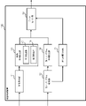
- FIG. 2 is a block diagram of the numerical controller 100.
- the numerical controller 100 includes a video acquisition unit 11 , a processing program acquisition unit 12 , a video feature detection unit 13 , a processing program feature detection unit 14 , an execution time calculation unit 15 and a data linking unit 16 .
- the image acquisition unit 11 acquires the processing image of the machine tool.
- the processed image may be obtained directly from an image captured by a camera, or may be obtained from the storage device of the numerical control device 100 or an external storage device.
- the machining program acquisition unit 12 acquires a machining program.
- the machining program is acquired from the storage device of the numerical controller 100 or an external storage device.
- the image feature detection unit 13 detects a characteristic frame from the frames included in the processed image, and marks the detected frame. Marking refers to, for example, embedding information indicating detection within a detected frame, or externally storing the frame number, time information, or the frame itself.
- the video feature detector 13 includes a manual detector 17 and an automatic detector 18 .
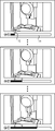
- the manual detection unit 17 presents the image to the operator and marks the image specified by the operator. For example, as shown in FIG. 3, an image being processed is displayed, and a seek bar 31 is displayed below the image. When the operator looks at the image, and if a characteristic image appears, such as a frame of tool exchange or a frame of ON/OFF of the machine light, marking is instructed.
- the seek bar in FIG. 3 displays anchors 32 indicating marked locations.
- the automatic detection unit 18 marks characteristic images using an image processing technique.
- luminance change and motion change are exemplified as image processing techniques, but are not limited thereto.
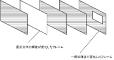
- FIG. 4 is an example of luminance change.
- Examples of luminance changes include a case where the luminance of the entire image changes, a case where the ratio of a specific luminance value changes, and a case where the luminance of the attention area changes.
- An example in which the luminance of the entire image changes is turning on/off the internal light of a machine tool. Machine lights in machine tools are normally off. When the operator is working, turn on the light inside the machine. When the cabin lights are turned on, the entire cabin becomes brighter and the brightness increases. Conversely, when the cabin light is turned off, the entire cabin becomes dark and the brightness decreases.
- the automatic detection section marks a frame in which the brightness of the entire video has changed significantly as a characteristic frame.
- FIG. 5 shows an example of detecting changes in brightness of a region of interest.
- it is set to a region of interest 51 where coolant is discharged.
- the coolant brightness ratio in the region of interest 51 is high, but when the coolant is OFF, the coolant brightness ratio in the image decreases.
- the brightness changes greatly depending on whether the coolant is turned on or off.
- the automatic detection unit 18 compares the sum of the amount of change in luminance of all pixels in the region of interest with a threshold, and detects a frame when the sum of the amount of change in luminance of all pixels in the region of interest exceeds the threshold. Mark as a frame.
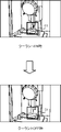
- FIG. 6 is an example of motion change.
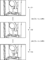
- image processing techniques are used to detect feature points and detect displacement vectors of the feature points.
- the automatic detection unit detects a frame 61 in which the movement amount of the feature point is large and a frame 62 in which the movement direction of the feature point changes greatly. Movement of feature points may be extracted from the entire image or may be extracted from the attention area 52 of the image.
- Feature point detection methods include, but are not limited to, SIFT (Scale-Invariant Feature Transform) and SURF (Speeded-UP Robust Features). SIFT and SURF detect corners of objects as feature points.
- the machining program feature detection unit 14 detects blocks (lines) of the machining program that command the machine tool to perform a characteristic operation.
- a block that commands a machine tool to perform a characteristic operation is, for example, a block in which a specific M code or a code with a large amount of change in axis movement is described.
- a specific M code instructs discharge/stop of coolant, storage of tools, tool change, work change, and the like.
- the machining program feature detection unit 14 extracts from the machining program a block in which an M code for commanding such a characteristic operation is described.
- Codes with a large amount of change in axis movement are [1] parts where the movement of the axis is reversed, [2] parts where the movement direction of the axis changes more than the threshold value, and [3] where the speed changes greatly, such as from cutting feed to rapid feed. This is the part to do.
- the amount of change in axis movement is known from the machining program. In the machining program of FIG. 8, the movement of the axis is reversed in the block described as "X-10.”, which satisfies the condition [1]. In the block described as "Y10.", the moving direction of the axis changes from the X-axis direction to the Y-axis direction, satisfying the condition [2].
- the machining program feature detection unit 14 thus detects a block that commands the machine tool to perform a feature operation.
- the execution time calculator 15 calculates the execution time of each block of the machining program.
- Methods of calculating the execution time include a method of calculating mathematically, a method of calculating by simulation, a method of calculating by actual measurement, and the like.
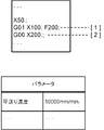
- the mathematical calculation method uses the command coordinate values, the feed rate, and the parameter information of the numerical controller 100 written in the machining program.
- a method of calculating the execution time will be described with reference to the machining program in FIG. As an example, the execution times of [1] 2nd line block "G01 X100.F200;” and [2] 3rd line block "G00 X200.;” are calculated. It is assumed that "rapid traverse speed: 10000 mm/min" is set for executing this machining program.
- the data linking unit 16 links the frames detected by the video feature detection unit 13 and the blocks detected by the processing program feature detection unit 14 .
- marks 1, 2 and 3 are marked. There are 1000 frames between mark 1 and mark 2. Assuming that the frame rate is 30 frames per second, it can be calculated that the interval between mark 1 and mark 2 is 33 seconds. The frame rate differs depending on the image compression method. Also, there are 2000 frames between mark 2 and mark 3 . Assuming that the frame rate is 30 frames per second, the time between mark 2 and mark 3 can be calculated as 66 seconds.
- Fig. 11 shows the relationship between the blocks of the machining program that command the machine tool to perform characteristic operations and the execution time.
- "M6” is a block that commands the machine tool to perform a characteristic operation of tool change.
- block A, block B, and block C are extracted as blocks that command the machine tool to perform characteristic operations.
- Block A describes "M6: Tool Change”
- Block B describes "M6: Tool Change”
- Block C describes "M9: Coolant OFF”.
- the data associating unit 16 associates a characteristic frame with a block that instructs a machine tool to perform a characteristic operation.
- mark 1 and block A, mark 2 and block B, and mark 3 and block C are linked.
- the data linking unit 16 links the remaining frames and blocks based on the linked frames and blocks.
- the block execution time is used for the correspondence.
- the corresponding frame can be calculated from the execution time of the block and the frame rate.
- the execution time of the block on the first line is 5 seconds
- the execution time of the block on the second line is 5 seconds
- the execution time of the block on the third line is 10 seconds.
- the product of execution time and frame rate is the number of frames per block. In this way, frames and blocks are associated with each other.
- the data linking unit 16 uses the execution time to associate frames with blocks, and excludes frames with no link partner and blocks with no link partner. 11 and 12 are examples in which the number of blocks is greater than the number of marks. 10, there are three marking locations, namely mark 1, mark 2, and mark 3. In FIG. 16, four blocks, block A, block B, block C, and block D, are extracted.
- the data associating unit 16 uses the time between block A and block B as “13 seconds”, the time between block B and block C as “20 seconds”, and the time between block C and block D as “67 seconds”. Then, determine which mark matches which block. In this example, there is no mark corresponding to block B. Therefore, block B is not used for tying, and blocks A, C, and D where tying partners exist are used.
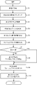
- Numerical control device 100 acquires an image (step S1).
- the numerical controller 100 marks the characteristic video (step S2).
- the method of marking may be manual or automatic.
- Numerical controller 100 acquires a machining program (step S3).
- the numerical controller 100 detects a block in the machining program that commands the machine tool to perform a characteristic operation (step S4).
- the numerical controller 100 calculates the execution time of each block of the machining program (step S5).
- Execution time calculation methods include a mathematical calculation method, a method of calculation by simulation, a method of calculation by actual measurement, and the like.
- the numerical controller 100 compares the number of marked frames and the number of detected blocks (step S6). If the number of marked frames and the number of detected blocks match (step S7; YES), the process proceeds to step S9. If the number of marked frames and the number of detected blocks are different (step S7; NO), the numerical controller 100 compares the time of the marked frame and the time of the detected block, Frames and blocks are detected as marks and blocks that can be linked (step S8).
- the numerical controller 100 associates the frame detected in step S2 with the block detected in step S4 (step S9).
- the numerical control device associates blocks other than the blocks associated in step S9 with video frames using the block execution time and frame rate (step S10). As a result, all blocks of the processing program are associated with video frames.
- the numerical control device 100 of the present disclosure can associate a video being processed with blocks of a processing program.
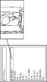
- By associating the video being processed with the processing program as shown in FIG. 14, it is possible to visually analyze the block and the content of processing by viewing the video.
- the numerical control device of the present disclosure associates images and processing programs with a simple mechanism.
- image processing there are also techniques for image analysis using machine learning.
- machine learning it is necessary to perform learning under certain conditions.
- the numerical control device of the present disclosure has a simple configuration because it uses general image processing techniques such as brightness change and displacement vector.
- image processing techniques such as brightness change and displacement vector.
- a machine learning detector specialized for the intended event may be created for each event.
- machine learning detectors specialized for events such as a detector that detects tool change, a detector that detects workpiece change, and a detector that detects coolant ON/OFF, are learned in advance, and which When even one score is equal to or higher than the threshold, it can be detected as a frame having video characteristics.
- a CPU 111 included in the numerical controller 100 is a processor that controls the numerical controller 100 as a whole.
- the CPU 111 reads the system program processed in the ROM 112 via the bus and controls the entire numerical controller 100 according to the system program.
- the RAM 113 temporarily stores calculation data, display data, various data input by the user via the input unit 71, and the like.
- the display unit 70 is a monitor attached to the numerical controller 100 or the like.
- the display unit 70 displays an operation screen, a setting screen, and the like of the numerical controller 100 .
- the input unit 71 is integrated with the display unit 70 or is a keyboard, touch panel, or the like that is separate from the display unit 70 .
- the user operates the input unit 71 to perform input to the screen displayed on the display unit 70 .
- the display unit 70 and the input unit 71 may be mobile terminals.
- the non-volatile memory 114 is, for example, a memory that is backed up by a battery (not shown) so that the memory state is retained even when the power of the numerical controller 100 is turned off.
- the nonvolatile memory 114 stores programs read from an external device via an interface (not shown), programs input via the input unit 71, and various data (for example, , setting parameters obtained from the machine tool, etc.) are stored. Programs and various data stored in the non-volatile memory 114 may be developed in the RAM 113 at the time of execution/use. Various system programs are pre-written in the ROM 112 .
- a controller 40 for controlling tools of a machine tool converts an axis movement command from the CPU 111 into a pulse signal and outputs the pulse signal to a driver 41 .
- a driver 41 converts the pulse signal into a current to drive a servomotor of the machine tool.
- a servo motor moves a tool and a table according to control of the numerical controller 100.
- FIG. The PLC 42 controls external equipment. External devices include a tool changer, coolant, and the like.
Landscapes
- Engineering & Computer Science (AREA)
- Physics & Mathematics (AREA)
- General Physics & Mathematics (AREA)
- Human Computer Interaction (AREA)
- Manufacturing & Machinery (AREA)
- Automation & Control Theory (AREA)
- Multimedia (AREA)
- Theoretical Computer Science (AREA)
- Computer Vision & Pattern Recognition (AREA)
- Software Systems (AREA)
- Numerical Control (AREA)
Abstract
Description
また、特許文献1では、『処理対象である機械データに動画データが含まれている場合に、動画データのフレーム画像のうち、所定の事象を示す予め設定された特徴が表れているフレームの時点を抽出してもよい』と記載されている。特許文献1では、画像解析により、工具がワークに接触したタイミング、又は離れたタイミングが検出できる。
しかしながら、特許文献1の技術は、加工時に取得したデータと加工プログラムとを紐づけるものではない。
本開示の一態様である映像解析システムは、数値制御装置の加工映像を取得する映像取得部と、数値制御装置の加工プログラムを取得する加工プログラム取得部と、加工映像に含まれるフレームのなかで、特徴のあるフレームを検出する映像特徴検出部と、加工プログラムに含まれるブロックのなかで、特徴のある動作を工作機械に指令するブロックを検出する加工プログラム特徴検出部と、特徴のあるフレームと特徴のある動作を工作機械に指令するブロックとを紐づけるデータ紐づけ部と、を備える。
本開示の一態様である記憶媒体は、1つ又は複数のプロセッサが実行することにより、数値制御装置の加工映像を取得し、数値制御装置の加工プログラムを取得し、加工映像に含まれるフレームのなかで、特徴のあるフレームを検出し、加工プログラムに含まれるブロックのなかで、特徴のある動作を工作機械に指令するブロックを検出し、特徴のあるフレームと特徴のある動作を工作機械に指令するブロックとを紐づける、コンピュータが読み取り可能な命令を記憶する。
図1に示すように、本開示では、映像解析装置を、数値制御装置100に実装する。映像解析装置は、PC(パーソナルコンピュータ)、サーバ、携帯端末などの情報処理装置に実装してもよい。また、映像解析装置の構成要素をネットワーク上の複数の情報処理装置で分散処理する映像解析システム1000としてもよい。
映像特徴検出部13は、手動検出部17と自動検出部18とを備える。手動検出部17は、オペレータに映像を提示し、オペレータが指定した映像にマーキングを行う。例えば、図3に示すように、加工中の映像を表示、映像の下にシークバー31を表示する。オペレータが映像を見て、工具交換をしているフレーム、機内灯がON/OFFしたフレームなど特徴のある映像が出現すると、マーキングを指示する。図3のシークバーには、マーキングされた箇所を示すアンカー32が表示されている。
図4は、輝度変化の例である。輝度変化の例としては、映像全体の輝度が変化する場合と、特定の輝度値の割合が変化する場合と、注目領域の輝度が変化する場合がある。
映像全体の輝度が変化する例として、工作機械の機内灯のON/OFFがある。工作機械の機内灯は通常OFFである。オペレータが作業するときは、機内灯をONする。機内灯をONすると、機内全体が明るくなり、輝度が高くなる。逆に機内灯をOFFすると機内全体が暗くなり、輝度が低くなる。自動検出部は、映像全体の輝度が大きく変化したフレームを、特徴のあるフレームとしてマーキングする。
図5では、クーラントが吐出される注目領域51に設定している。ワークの加工時、すなわち、クーラントがONのときには、注目領域51に占めるクーラントの輝度の割合が多いが、クーラントをOFFにすると映像に占めるクーラントの輝度の割合が少なくなる。クーラントのON/OFFによって輝度が大きく変化する。自動検出部18は、注目領域の全ピクセルの輝度の変化量の総和と閾値とを比較し、注目領域の全ピクセルの輝度の変化量の総和が閾値を超えたときのフレームを、特徴のあるフレームとしてマーキングする。
特徴点の検出方法には、例えば、SIFT(Scale-Invariant Feature Transform)やSURF(Speeded-UP Robust Features)があるがこれに限定されない。SIFTやSURFは、物体のコーナ部分などを特徴点として検出する。
実測による算出では、実行中のブロック(行)の番号を一定周期で問い合わせ、ブロック番号が変化したタイミングで1ブロックの実行時間を記録する。シミュレーションによる算出では、シミュレーションソフトがブロックごとの実行時間を算出する。なお、実行時間の算出方法は、特開2020-38671号公報などにすでに開示された既存の技術である。
データ紐づけ部16は、紐づけたフレームとブロックとを基準として、残りのフレームとブロックとを対応付ける。対応付けにはブロックの実行時間を用いる。ブロックの実行時間とフレームレートから対応するフレームが算出できる。図10の例では、1行目のブロックの実行時間が5秒、2行目のブロックの実行時間が5秒、3行目のブロックの実行時間が10秒である。実行時間とフレームレートの積がブロックごとのフレーム数である。このようにして、フレームとブロックとの対応付けを行う。
図11と図12は、ブロックの数がマークの数よりも多い例である。図10の映像のマーキング箇所は、マーク1、マーク2、マーク3と3箇所であるが、図16では、ブロックA、ブロックB、ブロックC、ブロックDの4つのブロックが抽出されている。データ紐づけ部16は、ブロックAとブロックBの間の時間「13秒」、ブロックBとブロックCの間の時間「20秒」、ブロックCとブロックDの間の時間「67秒」を基に、どのマークとどのブロックが一致するか判断する。この例では、ブロックBに対応するマークが存在しない。そのため、ブロックBを紐づけに使用せず、紐づけ相手の存在するブロックA、C、Dを使用する。
数値制御装置100は、加工プログラムを取得する(ステップS3)。数値制御装置100は、加工プログラムのうち、特徴のある動作を工作機械に指令するブロックを検出する(ステップS4)。
数値制御装置は、ブロックの実行時間とフレームレートを用いて、ステップS9で紐づけられたブロック以外のブロックと映像のフレームを紐づける(ステップS10)。これにより、加工プログラムの全てのブロックが映像のフレームと紐づけられる。
本開示の数値制御装置では、輝度変化や変位ベクトルなどの一般的な画像処理の手法を用いるため構成が簡単である。手動で特徴のある映像にマーキングする場合には、人間が映像の判定を行うので、さらに簡単な構成で、映像とプログラムの紐づけが実現できる。
図15を参照して、数値制御装置100のハードウェア構成を説明する。数値制御装置100が備えるCPU111は、数値制御装置100を全体的に制御するプロセッサである。CPU111は、バスを介してROM112に加工されたシステム・プログラムを読み出し、該システム・プログラムに従って数値制御装置100の全体を制御する。RAM113には、一時的な計算データや表示データ、入力部71を介してユーザが入力した各種データ等が一時的に格納される。
PLC42は、外部機器を制御する。外部機器には、工具交換機、クーラントなどがある。
11 映像取得部
12 加工プログラム取得部
13 映像特徴検出部
14 加工プログラム特徴検出部
15 実行時間算出部
16 データ紐づけ部
17 手動検出部
18 自動検出部
50、51、52 注目領域
111 CPU
112 ROM
113 RAM
114 不揮発性メモリ
Claims (8)
- 数値制御装置の加工映像を取得する映像取得部と、
前記数値制御装置の加工プログラムを取得する加工プログラム取得部と、
前記加工映像に含まれるフレームのなかで、特徴のあるフレームを検出する映像特徴検出部と、
前記加工プログラムに含まれるブロックのなかで、特徴のある動作を工作機械に指令するブロックを検出する加工プログラム特徴検出部と、
前記特徴のあるフレームと前記特徴のある動作を工作機械に指令するブロックとを紐づけるデータ紐づけ部と、
を備える映像解析装置。 - 前記加工プログラムに含まれる各ブロックの実行時間を算出する実行時間算出部を備え、
前記データ紐づけ部は、前記特徴のあるフレームと前記特徴のある動作を工作機械に指令するブロックとの紐づけを基準として、前記各ブロックの実行時間及び前記加工映像のフレームレートを基に、前記加工映像に含まれるフレームと前記加工プログラムに含まれるブロックの紐づけを行う、請求項1記載の映像解析装置。 - 前記データ紐づけ部は、前記ブロックの実行時間を基に、前記特徴のあるフレームと、前記特徴のある動作を工作機械に指令するブロックとを対応付け、紐づけ相手のないフレーム、及び紐づけ相手のないブロックを除外する、請求項2記載の映像解析装置。
- 前記映像特徴検出部は、オペレータからの入力を受け付け、オペレータの指示に基づき前記特徴のあるフレームを検出する手動検出部を備える、請求項1記載の映像解析装置。
- 前記映像特徴検出部は、輝度変化又はモーション変化の少なくとも一方に基づき前記特徴のあるフレームを検出する自動検出部を備える、請求項1記載の映像解析装置。
- 前記加工プログラム特徴検出部は、前記ブロックに含まれるコードの種類及びコードの座標値を基に、特徴のある動作を工作機械に指令するブロックを検出する、請求項1記載の映像解析装置。
- 数値制御装置の加工映像を取得する映像取得部と、
前記数値制御装置の加工プログラムを取得する加工プログラム取得部と、
前記加工映像に含まれるフレームのなかで、特徴のあるフレームを検出する映像特徴検出部と、
前記加工プログラムに含まれるブロックのなかで、特徴のある動作を工作機械に指令するブロックを検出する加工プログラム特徴検出部と、
前記特徴のあるフレームと前記特徴のある動作を工作機械に指令するブロックとを紐づけるデータ紐づけ部と、
を備える映像解析システム。 - 1つ又は複数のプロセッサが実行することにより、
数値制御装置の加工映像を取得し、
前記数値制御装置の加工プログラムを取得し、
前記加工映像に含まれるフレームのなかで、特徴のあるフレームを検出し、
前記加工プログラムに含まれるブロックのなかで、特徴のある動作を工作機械に指令するブロックを検出し、
前記特徴のあるフレームと前記特徴のある動作を工作機械に指令するブロックとを紐づける、
コンピュータが読み取り可能な命令を記憶する記憶媒体。
Priority Applications (5)
| Application Number | Priority Date | Filing Date | Title |
|---|---|---|---|
| DE112021007323.0T DE112021007323T5 (de) | 2021-05-24 | 2021-05-24 | Videoanalysevorrichtung, videoanalysesystem und speichermedium |
| US18/557,047 US20240219887A1 (en) | 2021-05-24 | 2021-05-24 | Video analysis device, video analysis system, and storage medium |
| PCT/JP2021/019643 WO2022249249A1 (ja) | 2021-05-24 | 2021-05-24 | 映像解析装置、映像解析システム、及び記憶媒体 |
| CN202180098344.9A CN117321515A (zh) | 2021-05-24 | 2021-05-24 | 影像解析装置、影像解析系统以及存储介质 |
| JP2023523730A JPWO2022249249A1 (ja) | 2021-05-24 | 2021-05-24 |
Applications Claiming Priority (1)
| Application Number | Priority Date | Filing Date | Title |
|---|---|---|---|
| PCT/JP2021/019643 WO2022249249A1 (ja) | 2021-05-24 | 2021-05-24 | 映像解析装置、映像解析システム、及び記憶媒体 |
Publications (2)
| Publication Number | Publication Date |
|---|---|
| WO2022249249A1 true WO2022249249A1 (ja) | 2022-12-01 |
| WO2022249249A9 WO2022249249A9 (ja) | 2023-09-28 |
Family
ID=84229703
Family Applications (1)
| Application Number | Title | Priority Date | Filing Date |
|---|---|---|---|
| PCT/JP2021/019643 Ceased WO2022249249A1 (ja) | 2021-05-24 | 2021-05-24 | 映像解析装置、映像解析システム、及び記憶媒体 |
Country Status (5)
| Country | Link |
|---|---|
| US (1) | US20240219887A1 (ja) |
| JP (1) | JPWO2022249249A1 (ja) |
| CN (1) | CN117321515A (ja) |
| DE (1) | DE112021007323T5 (ja) |
| WO (1) | WO2022249249A1 (ja) |
Citations (3)
| Publication number | Priority date | Publication date | Assignee | Title |
|---|---|---|---|---|
| JP3543147B2 (ja) * | 2001-07-10 | 2004-07-14 | ヤマザキマザック株式会社 | 工作機械の異常管理装置 |
| JP5620446B2 (ja) * | 2012-09-24 | 2014-11-05 | ファナック株式会社 | Gコード指令によりビデオカメラを操作する機能を備えた数値制御装置 |
| JP6656387B2 (ja) * | 2016-09-09 | 2020-03-04 | マキノジェイ株式会社 | 表示装置を備えた工作機械 |
Family Cites Families (8)
| Publication number | Priority date | Publication date | Assignee | Title |
|---|---|---|---|---|
| US6567162B2 (en) * | 2001-05-31 | 2003-05-20 | The Regents Of The University Of Michigan | Reconfigurable apparatus and method for inspection during a manufacturing process |
| JP2004038624A (ja) * | 2002-07-04 | 2004-02-05 | Nissan Motor Co Ltd | 車両認識方法、車両認識装置及び車両認識用プログラム |
| WO2007030731A2 (en) * | 2005-09-07 | 2007-03-15 | Nr Laboratories, Llc | Positional sensing system and method |
| JP2016194843A (ja) * | 2015-04-01 | 2016-11-17 | ファナック株式会社 | 複数画像を用いたプログラム表示機能を有する数値制御装置 |
| JP2018041247A (ja) * | 2016-09-07 | 2018-03-15 | ファナック株式会社 | 機械の個体識別情報を認識するためのサーバ、方法、プログラム、及びシステム |
| US10518480B2 (en) * | 2018-04-02 | 2019-12-31 | Nanotronics Imaging, Inc. | Systems, methods, and media for artificial intelligence feedback control in additive manufacturing |
| JP6806737B2 (ja) | 2018-06-15 | 2021-01-06 | ファナック株式会社 | 同期装置、同期方法及び同期プログラム |
| JP7412927B2 (ja) | 2018-09-04 | 2024-01-15 | キヤノンメディカルシステムズ株式会社 | 医用情報管理システム、医用情報管理装置、および、医用情報管理方法 |
-
2021
- 2021-05-24 DE DE112021007323.0T patent/DE112021007323T5/de not_active Withdrawn
- 2021-05-24 WO PCT/JP2021/019643 patent/WO2022249249A1/ja not_active Ceased
- 2021-05-24 CN CN202180098344.9A patent/CN117321515A/zh not_active Withdrawn
- 2021-05-24 US US18/557,047 patent/US20240219887A1/en active Pending
- 2021-05-24 JP JP2023523730A patent/JPWO2022249249A1/ja active Pending
Patent Citations (3)
| Publication number | Priority date | Publication date | Assignee | Title |
|---|---|---|---|---|
| JP3543147B2 (ja) * | 2001-07-10 | 2004-07-14 | ヤマザキマザック株式会社 | 工作機械の異常管理装置 |
| JP5620446B2 (ja) * | 2012-09-24 | 2014-11-05 | ファナック株式会社 | Gコード指令によりビデオカメラを操作する機能を備えた数値制御装置 |
| JP6656387B2 (ja) * | 2016-09-09 | 2020-03-04 | マキノジェイ株式会社 | 表示装置を備えた工作機械 |
Also Published As
| Publication number | Publication date |
|---|---|
| WO2022249249A9 (ja) | 2023-09-28 |
| CN117321515A (zh) | 2023-12-29 |
| JPWO2022249249A1 (ja) | 2022-12-01 |
| US20240219887A1 (en) | 2024-07-04 |
| DE112021007323T5 (de) | 2024-02-29 |
Similar Documents
| Publication | Publication Date | Title |
|---|---|---|
| JP4784752B2 (ja) | 画像処理装置 | |
| US20150161808A1 (en) | Simulator, simulation method, and simulation program | |
| US20180027218A1 (en) | Work assistance device, work assistance system, work assistance method, and recording medium storing work assistance program | |
| CN110599441A (zh) | 接缝检查装置 | |
| JP6922239B2 (ja) | 工程監視装置、工程監視装置の制御方法およびプログラム | |
| CN112783935A (zh) | 分析装置 | |
| US20160110611A1 (en) | Numerical control device | |
| JP7401280B2 (ja) | 作業工程判別装置及び作業工程判別システム | |
| WO2022249249A1 (ja) | 映像解析装置、映像解析システム、及び記憶媒体 | |
| JP7170493B2 (ja) | 締め付け確認システム、及び当該締め付け確認システムを用いた方法 | |
| US20210157298A1 (en) | Program restart assisting apparatus | |
| JP7712373B2 (ja) | 教示装置及びロボットシステム | |
| JP6962858B2 (ja) | 画像管理装置 | |
| US20240091945A1 (en) | Industrial machine system | |
| JP7664865B2 (ja) | 加工支援装置及び加工システム | |
| US11321656B2 (en) | Difference extracting device | |
| JP6948294B2 (ja) | 作業異常検知支援装置、作業異常検知支援方法、および作業異常検知支援プログラム | |
| US20240201650A1 (en) | Operational status display device and computer-readable storage medium | |
| JP2008009938A (ja) | 動画像データ処理装置、動画像データ処理方法、動画像データ処理プログラム、およびこれを記録した記録媒体 | |
| US20220122482A1 (en) | Smart system for adapting and enforcing processes | |
| US20250200482A1 (en) | Work analyzing device and work analyzing method | |
| WO2024062541A9 (ja) | 画像生成システム及びコンピュータ読み取り可能な記録媒体 | |
| JPH0821081B2 (ja) | ウィンドウの制御方法 | |
| WO2023218653A1 (ja) | 映像管理装置、及びコンピュータが読み取り可能な記憶媒体 | |
| TW202445509A (zh) | 圖像處理方法、程式、圖像處理系統、圖像處理裝置及檢測裝置 |
Legal Events
| Date | Code | Title | Description |
|---|---|---|---|
| 121 | Ep: the epo has been informed by wipo that ep was designated in this application |
Ref document number: 21942906 Country of ref document: EP Kind code of ref document: A1 |
|
| WWE | Wipo information: entry into national phase |
Ref document number: 2023523730 Country of ref document: JP |
|
| WWE | Wipo information: entry into national phase |
Ref document number: 18557047 Country of ref document: US |
|
| WWE | Wipo information: entry into national phase |
Ref document number: 112021007323 Country of ref document: DE |
|
| WWE | Wipo information: entry into national phase |
Ref document number: 202180098344.9 Country of ref document: CN |
|
| 122 | Ep: pct application non-entry in european phase |
Ref document number: 21942906 Country of ref document: EP Kind code of ref document: A1 |