WO2022244666A1 - プリンタシステム - Google Patents
プリンタシステム Download PDFInfo
- Publication number
- WO2022244666A1 WO2022244666A1 PCT/JP2022/019999 JP2022019999W WO2022244666A1 WO 2022244666 A1 WO2022244666 A1 WO 2022244666A1 JP 2022019999 W JP2022019999 W JP 2022019999W WO 2022244666 A1 WO2022244666 A1 WO 2022244666A1
- Authority
- WO
- WIPO (PCT)
- Prior art keywords
- housing
- printing paper
- module
- printer
- printer module
- Prior art date
- Legal status (The legal status is an assumption and is not a legal conclusion. Google has not performed a legal analysis and makes no representation as to the accuracy of the status listed.)
- Ceased
Links
Images




Classifications
-
- B—PERFORMING OPERATIONS; TRANSPORTING
- B41—PRINTING; LINING MACHINES; TYPEWRITERS; STAMPS
- B41J—TYPEWRITERS; SELECTIVE PRINTING MECHANISMS, i.e. MECHANISMS PRINTING OTHERWISE THAN FROM A FORME; CORRECTION OF TYPOGRAPHICAL ERRORS
- B41J15/00—Devices or arrangements of selective printing mechanisms, e.g. ink-jet printers or thermal printers, specially adapted for supporting or handling copy material in continuous form, e.g. webs
- B41J15/04—Supporting, feeding, or guiding devices; Mountings for web rolls or spindles
-
- B—PERFORMING OPERATIONS; TRANSPORTING
- B41—PRINTING; LINING MACHINES; TYPEWRITERS; STAMPS
- B41J—TYPEWRITERS; SELECTIVE PRINTING MECHANISMS, i.e. MECHANISMS PRINTING OTHERWISE THAN FROM A FORME; CORRECTION OF TYPOGRAPHICAL ERRORS
- B41J15/00—Devices or arrangements of selective printing mechanisms, e.g. ink-jet printers or thermal printers, specially adapted for supporting or handling copy material in continuous form, e.g. webs
- B41J15/16—Means for tensioning or winding the web
-
- B—PERFORMING OPERATIONS; TRANSPORTING
- B41—PRINTING; LINING MACHINES; TYPEWRITERS; STAMPS
- B41J—TYPEWRITERS; SELECTIVE PRINTING MECHANISMS, i.e. MECHANISMS PRINTING OTHERWISE THAN FROM A FORME; CORRECTION OF TYPOGRAPHICAL ERRORS
- B41J29/00—Details of, or accessories for, typewriters or selective printing mechanisms not otherwise provided for
- B41J29/02—Framework
-
- B—PERFORMING OPERATIONS; TRANSPORTING
- B41—PRINTING; LINING MACHINES; TYPEWRITERS; STAMPS
- B41J—TYPEWRITERS; SELECTIVE PRINTING MECHANISMS, i.e. MECHANISMS PRINTING OTHERWISE THAN FROM A FORME; CORRECTION OF TYPOGRAPHICAL ERRORS
- B41J29/00—Details of, or accessories for, typewriters or selective printing mechanisms not otherwise provided for
- B41J29/12—Guards, shields or dust excluders
- B41J29/13—Cases or covers
-
- B—PERFORMING OPERATIONS; TRANSPORTING
- B41—PRINTING; LINING MACHINES; TYPEWRITERS; STAMPS
- B41J—TYPEWRITERS; SELECTIVE PRINTING MECHANISMS, i.e. MECHANISMS PRINTING OTHERWISE THAN FROM A FORME; CORRECTION OF TYPOGRAPHICAL ERRORS
- B41J3/00—Typewriters or selective printing or marking mechanisms characterised by the purpose for which they are constructed
- B41J3/42—Two or more complete typewriters coupled for simultaneous operation
-
- H—ELECTRICITY
- H05—ELECTRIC TECHNIQUES NOT OTHERWISE PROVIDED FOR
- H05K—PRINTED CIRCUITS; CASINGS OR CONSTRUCTIONAL DETAILS OF ELECTRIC APPARATUS; MANUFACTURE OF ASSEMBLAGES OF ELECTRICAL COMPONENTS
- H05K5/00—Casings, cabinets or drawers for electric apparatus
- H05K5/02—Details
Definitions
- the present disclosure relates to a printer system that can be easily and simply assembled by combining multiple modules.
- a printer system that combines multiple modules is known as a sublimation printer.
- the present disclosure has been made in consideration of such points, and aims to provide a printer system that has a simple structure and can be easily and simply assembled.
- the present disclosure includes three or more modules that are arranged in series and connected to each other, the upstream module has a printing paper supply function to supply printing paper, and the downstream module winds the printing paper.
- Another module includes a printer module that has a print paper winding function and prints on the print paper, and the module is provided on one side of the housing and protruding from the one side of the housing.
- 1 is a first printer system having a smaller linkage; According to the present disclosure, in the first printer system, an insertion hole is formed in one of the outer surface of the connecting body and the other surface of the housing facing the one surface, and the module is inserted into the insertion hole of the module adjacent to the other.
- a second printer system is provided with an insertion pin that is attached to the printer.
- the present disclosure is a fourth printer system, wherein, in the first to third printer systems, the height of the connecting body of the module is 1/4 to 1/2 of the height of the housing. is.
- the present disclosure is a fifth printer system in which, in the first to fourth printer systems, the width of the connecting body of the modules is the same as the width of the housing.
- the present disclosure is a sixth printer system in which a guide path for the printing paper is provided in the travel area between the housings in the first to fifth printer systems.
- the present disclosure is an eighth printer system in which a plurality of the printer modules are installed in the first to seventh printer systems.
- the present disclosure is a ninth printer system in which, in the first to eighth printer systems, a plurality of the insertion pins and the insertion holes of the module are arranged horizontally.
- a first contact is provided on one of the outer surface of the connecting body and the other surface of the housing, and the first contact of a module adjacent to the other is provided.
- the eleventh printer system is provided with a second contact that can be electrically connected to the .
- FIG. 1 is a schematic perspective view showing a printer system according to a first embodiment
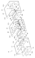
- FIG. FIG. 2 is an exploded perspective view showing the printer system according to the first embodiment
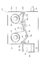
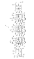
- 3 is a side view showing a printer module of the printer system according to the first embodiment
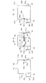
- FIG. 4 is a side view showing the printer system before assembly according to the first embodiment
- FIG. 5 is a side view showing the printer system after assembly according to the first embodiment
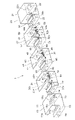
- FIG. 6 is a schematic perspective view showing a printer system according to a second embodiment
- FIG. 7 is an exploded perspective view showing a printer system according to a second embodiment
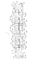
- FIG. 8 is a side view showing the printer system before assembly according to the second embodiment
- FIG. 9 is a side view showing the assembled printer system according to the second embodiment
- FIG. 10 is a schematic perspective view showing a printer system according to a third embodiment
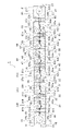
- FIG. 11 is a side view showing a printer system according to a third embodiment
- 1 to 5 are diagrams showing the first embodiment of the present disclosure.
- FIG. 1 the printer system 1 according to the first embodiment will be described with reference to FIGS. 1 to 5.
- FIG. 1 the printer system 1 according to the first embodiment will be described with reference to FIGS. 1 to 5.
- the printer system 1 includes three modules 10, 30, 20 arranged in series and connected to each other.
- the module 10 on the upstream side serves as a printing paper supply module 10 having a printing paper supply function for supplying the rolled printing paper W
- the module 20 on the downstream side serves as a printing paper winding module with a function of winding the printed printing paper W.
- a picking module 20 is provided.
- a printer module 30 for printing on the printing paper W is installed between the printing paper supply module 10 and the printing paper take-up module 20 .
- the printing paper supply module 10 has a housing 11 and a printing paper supply unit 17 built in the housing 11 .
- the printing paper W supplied from the printing paper supply unit 17 is guided by the guide roller 18a and the nip roller 18b and sent to the printer module 30 through the opening 12b of the other surface 11b, which will be described later.
- the printing paper winding module 20 also has a housing 21 and a printing paper winding section 27 built in the housing 21 .
- the printing paper W printed by the printer module 30 enters through an opening 22a on one side 21a, which will be described later, and is guided by a nip roller 28a and a guide roller 28b and wound by the printing paper take-up unit 27. be taken.
- the printer module 30 includes a housing 31, an ink ribbon supply section 37 provided in the housing 31 for supplying the ink ribbon 39, and an ink ribbon winding section provided in the housing 31 for winding the ink ribbon 39. 38.
- a thermal head 90 and a platen roller 91 are provided in the housing 31 to sandwich the printing paper W and the ink ribbon 39 and print on the printing paper W. As shown in FIG.
- a nip roller 92a and a guide roller 92b are provided in the housing 31 to guide the printing paper W sent from the printing paper supply module 10 to the thermal head 90 side. Further, the print paper W printed by the thermal head 90 is discharged to the print paper take-up module 20 side through the opening 32b provided on the other surface 31b of the housing 31 via the nip rollers 93a and 93b.
- the housing 31 there are guide paths 95 for guiding the printing paper W between the nip roller 92a and the guide roller 92b, between the guide roller 92b and the platen roller 91, and between the nip roller 93a and the nip roller 93b. is provided.
- These guide paths 95 are supported inside the housing 31 by a support mechanism (not shown).
- the ink ribbon 39 supplied from the ink ribbon supply unit 37 built in the printer module 30 contains three colors of yellow, magenta, and cyan, and an overcoat layer. With only the ink ribbon 39, it is possible to print the three colors of yellow, magenta, and cyan on the printing paper W and the OP layer.
- the printing paper supply module 10 has the rectangular parallelepiped housing 11 and the rectangular parallelepiped connector 15 provided on one surface 11a of the housing 11 and protruding from the one surface 11a.
- Two insertion holes 16 are formed in one of the outer surface 15a of the connector 15 and the other surface 11b facing the one surface 11a, for example, horizontally aligned in the outer surface 15a of the connector 15.
- two insertion pins 13 are horizontally arranged to be inserted into insertion holes 36 provided in a connecting body 35 (described later) of the printer module 30 adjacent to the other surface 11b.
- the printing paper take-up module 20 has the rectangular parallelepiped housing 21 and the rectangular parallelepiped coupling body 25 provided on the one surface 21a of the housing 21 and protruding from the one surface 21a as described above.
- Two insertion holes 26 are formed in one of the outer surface 25a of the connecting member 25 and the other surface 21b opposite to the one surface 21a, for example, horizontally aligned in the outer surface 25a of the connecting member 25.
- two insertion pins 23 are provided horizontally on the other side 21b.
- the printer module 30 has the rectangular parallelepiped housing 31 and the rectangular parallelepiped connecting body 35 provided on one surface 31a of the housing 31 so as to protrude from the one surface 31a.
- Two insertion holes 36 are formed in one of the outer surface 35a of the connector 35 and the other surface 35b opposite to the one surface 31a, for example, horizontally aligned in the outer surface 35a of the connector 35.
- two insertion pins 33 are arranged horizontally and are inserted into insertion holes 26 provided in the connecting body 25 of the print paper take-up module 20 adjacent to the other surface 31b.
- the housing 11 of the printing paper supply module 10 has a rectangular parallelepiped shape, and is larger than the rectangular parallelepiped connecting body 15 .
- the connector 15 has substantially the same width as the housing 11, and its height is about 1/4 to 1/2 of the height of the housing 11.
- the width of the connecting body 15 and the housing 11 means the width along the direction orthogonal to the running direction of the printing paper W. As shown in FIG.
- the casing 21 of the printing paper winding module 20 has a rectangular parallelepiped shape, and is larger than the connecting body 25 which is also rectangular parallelepiped.
- the connector 25 has substantially the same width as the housing 21, and its height is about 1/4 to 1/2 of the height of the housing 21.
- the width of the connecting body 25 and the housing 21 refers to the width along the direction orthogonal to the running direction of the printing paper W. As shown in FIG.
- the housing 31 of the printer module 30 has a rectangular parallelepiped shape and is larger than the connecting body 35 which is also rectangular parallelepiped.
- the connector 35 has substantially the same width as the housing 31, and its height is about 1/4 to 1/2 of the height of the housing 31.
- the width of the connecting body 35 and the housing 31 refers to the width along the direction orthogonal to the running direction of the printing paper W. As shown in FIG.
- openings 12a and 12b through which the printing paper W passes are provided above the connector 15 on one surface 11a and the other surface 11b of the housing 11 of the printing paper supply module 10, respectively.
- a first contact 81 a is provided on the other surface 11 b of the housing 11
- a second contact 81 b is provided on the outer surface 15 a of the connector 15 .
- openings 22a and 22b through which the printing paper W passes are provided above the connector 25 on one surface 21a and the other surface 21b of the housing 21 of the printing paper winding module 20, respectively.
- a first contact 81a is provided on the other surface 21b of the housing 21, and a second contact 81b electrically connected to the first contact 81a of the adjacent printer module 30 is provided on the outer surface 25a of the connector 25.
- openings 32a and 32b through which the printing paper W passes are provided above the connector 35 on one surface 31a and the other surface 31b of the housing 31 of the printer module 30, respectively.
- a first contact 81a is provided on the other surface 31b of the housing 31 .
- the outer surface 35a of the connecting body 35 is provided with a second contact 81b electrically connected to the first contact 81a of the adjacent printing paper supply module 10. As shown in FIG.
- the housing 11 and connecting body 15 of the printing paper supply module 10, the housing 21 and connecting body 25 of the printing paper take-up module 20, and the housing 31 and connecting body 35 of the printer module 30 are all the same. preferably have the same outline and the same structure.
- the housing 11 and connecting body 15 of the printing paper supply module 10, the housing 21 and connecting body 25 of the printing paper take-up module 20, and the housing 31 and connecting body 35 of the printer module 30 have the same outer shape and
- each module 10, 20, 30 can be easily assembled by using housings and connectors having the same external shape and the same structure, and arranging corresponding internal structures within each module within the housing. can be made.
- the printing paper supply module 10 the printing paper take-up module 20, and the printer module 30 are prepared.
- the printing paper supply unit 17 is not yet arranged in the housing 11 of the printing paper supply module 10, and the printing paper winding unit 27 is not yet arranged in the housing 21 of the printing paper winding module 20. Not placed.
- the other surface 11b of the housing 11 of the printing paper supply module 10 and the outer surface 35a of the connector 35 of the printer module 30 are joined.
- the insertion pin 13 provided in the housing 11 of the printing paper supply module 10 is inserted into the insertion hole 36 provided in the connector 35 of the printer module 30 .
- the first contact 81 a provided on the housing 11 of the printing paper supply module 10 is electrically connected to the second contact 81 b provided on the connector 35 of the printer module 30 .
- Information that the first contact 81 a and the second contact 81 b are connected is sent to the external control circuit 9 .
- the housing 31 of the printer module 30 and the connecting body 25 of the printing paper take-up module 20 can be accurately positioned and joined together.
- the printing paper W sent into the housing 31 of the printer module 30 is sent between the thermal head 90 and the platen roller 91 through the nip roller 92a, the guide roller 92b and the guide path 95 in sequence.
- the printing paper W passes through the nip roller 28a and the guide roller 28b in order and is wound up by the printing paper winding section 27.
- the other surface 11b of the housing 11 of the printing paper supply module 10 and the outer surface 35a of the connector 35 of the printer module 30 are joined, and the insertion pins 13 provided in the housing 11 are connected. is inserted into the insertion hole 36 provided in the connecting body 35 .
- the printing paper supply module 10 and the printer module 30 can be assembled easily and accurately.
- connecting bodies 35, 25 smaller than the housings 11, 31, 21 are interposed between the housings 11, 31, 21 of the respective modules 10, 30, 20, and the heights of the connecting bodies 15, 35, 25 are is kept low compared to the housings 11, 31, and 21.
- the openings 12a, 12b, 32a, 32b, 22a, 22b of the housings 11, 31, 21 are arranged above the connectors 15, 35, 25.
- FIG. As a result, between the housings 11 , 31 , 21 , the areas above the connecting members 35 , 25 can be used as a running area for the printing paper W.
- FIG. By setting the widths of the housings 11, 31, and 21 to be the same as the widths of the connecting bodies 15, 35, and 25, the printer system 10 as a whole has a uniform width in the direction perpendicular to the running direction of the printing paper W. be done.
- the printer system 1 includes five modules 10, 30A, 40, 50, 20 which are arranged in series and connected to each other.
- the module 10 on the upstream side serves as a printing paper supply module 10 having a printing paper supply function for supplying the rolled printing paper W
- the module 20 on the downstream side serves as a printing paper winding module with a function of winding the printed printing paper W.
- a picking module 20 is provided.
- the YMC printer module 30A includes a housing 31, an ink ribbon supply unit 37A provided in the housing 31 for supplying the ink ribbon 39A, and an ink ribbon winding unit 37A provided in the housing 31 for winding the ink ribbon 39A. and a portion 38A.
- a thermal head 90 and a platen roller 91 are provided in the housing 31 for printing on the printing paper W while holding the printing paper W and the ink ribbon 39A therebetween.
- These guide paths 95 are supported inside the housing 31 by a support mechanism (not shown).
- the spot color printer module 40 includes a housing 41, an ink ribbon supply unit 47 provided in the housing 41 for supplying the ink ribbon 49, and an ink ribbon winding unit 47 provided in the housing 41 for winding the ink ribbon 49. a portion 48; In addition, a thermal head 90 and a platen roller 91 for printing on the printing paper W while sandwiching the printing paper W and the ink ribbon 49 are provided in the housing 41 .
- the housing 41 of the spot color printer module 40 is provided with a guide path 95 for guiding the printing paper W sent from the YMC printer module 30A on one surface 41a of the housing 41 (see FIG. 6).
- These guide paths 95 are supported inside the housing 41 by a support mechanism (not shown).
- the OP layer printer module 50 includes a housing 51, an ink ribbon supply unit 57 provided in the housing 51 for supplying the ink ribbon 59, and an ink ribbon winding unit provided in the housing 51 for winding the ink ribbon 59. and a cutout portion 58 .
- a thermal head 90 and a platen roller 91 for printing on the printing paper W while holding the printing paper W and the ink ribbon 59 are provided in the housing 51 .
- a nip roller 92a and a guide roller 92b are provided in the housing 51 for guiding the printing paper W sent from the spot color printer module 40 to the thermal head 90 side. Further, the print paper W printed by the thermal head 90 is discharged to the print paper take-up module 20 side through the opening 52b provided on the other surface 51b of the housing 51 via the nip rollers 93a and 93b.
- These guide paths 95 are supported inside the housing 51 by a support mechanism (not shown).
- the printing paper supply module 10 has the rectangular parallelepiped housing 11 and the rectangular parallelepiped connecting body 15 provided on one surface 11a of the housing 11 so as to protrude from the one surface 11a.
- Two insertion holes 16 are formed in one of the outer surface 15a of the connector 15 and the other surface 11b facing the one surface 11a, for example, horizontally aligned in the outer surface 15a of the connector 15.
- two insertion pins 13 are horizontally arranged to be inserted into insertion holes 36 provided in a connecting body 35 (described later) of the YMC printer module 30A adjacent to the other surface 11b.
- the housing 11 of the printing paper supply module 10 has a rectangular parallelepiped shape, and is larger than the rectangular parallelepiped connecting body 15 .
- the connector 15 has substantially the same width as the housing 11, and its height is about 1/4 to 1/2 of the height of the housing 11.
- the width of the connecting body 15 and the housing 11 means the width along the direction orthogonal to the running direction of the printing paper W. As shown in FIG.
- the casing 21 of the printing paper winding module 20 has a rectangular parallelepiped shape, and is larger than the connecting body 25 which is also rectangular parallelepiped.
- the connector 25 has substantially the same width as the housing 21, and its height is about 1/4 to 1/2 of the height of the housing 21.
- the width of the connecting body 25 and the housing 21 refers to the width along the direction orthogonal to the running direction of the printing paper W. As shown in FIG.
- openings 32a and 32b through which the printing paper W passes are provided above the connector 35 on one side and the other side 31b of the housing 31 of the YMC printer module 30A.
- a first contact 81a is provided on the other surface 31b of the housing 31 .
- the outer surface 35a of the connecting member 35 is provided with a second contact 81b electrically connected to the first contact 81a of the adjacent printing paper supply module.
- openings 42a and 42b through which the printing paper W passes are provided above the connector 45 on one surface 41a and the other surface 41b of the housing 41 of the spot color printer module 40, respectively.
- a first contact 81a is provided.
- the outer surface 45a of the connecting body 45 is provided with a second contact 81b electrically connected to the first contact 81a of the adjacent YMC printer module 30A.
- the housing 11 and the connecting body 15 of the printing paper supply module 10 the housing 21 and the connecting body 25 of the printing paper take-up module 20, the housing 31 and the connecting body 35 of the YMC printer module 30A, and the spot color printer.
- the housing 41 and connecting body 45 of the module 40 and the housing 51 and connecting body 55 of the OP layer printer module 50 preferably have the same outer shape and the same structure.
- the printing paper supply unit 17 is not yet arranged in the housing 11 of the printing paper supply module 10, and the printing paper winding unit is also installed in the housing 21 of the printing paper winding module 20. 27 has not yet been placed.
- the YMC printer module 30A and the spot color printer module 40 are joined, and the spot color printer module 40 and the OP layer printer module 50 are joined.
- the first contact 81a provided on the casing 51 of the OP layer printer module 50 is electrically connected to the second contact 81b provided on the casing 21 of the printing paper take-up module 20. Information that the first contact 81 a and the second contact 81 b are connected is sent to the external control circuit 9 .
- the casing 51 of the OP layer printer module 50 and the connecting body 25 of the printing paper take-up module 20 can be accurately positioned and joined together.
- the printing paper supply section 17 is installed inside the housing 11 of the printing paper supply module 10 .
- a printing paper winding section 27 is installed in the housing 21 of the printing paper winding module 20 .
- the printer system 1 is obtained (see FIG. 9).
- the printing paper W is supplied from the printing paper supply unit 17 arranged inside the housing 11 of the printing paper supply module 10 .
- the printing paper W passes through the guide roller 18a and the nip roller 18b in the housing 11, is discharged from the opening 12b of the housing 11, is guided to the guide path 95 of the YMC printer module 30A, and is guided to the housing of the YMC printer module 30A through the opening 32a. Enter body 31 .
- the printing paper W sent into the housing 31 of the YMC printer module 30A is sent between the thermal head 90 and the platen roller 91 through the nip roller 92a, the guide roller 92b and the guide path 95 in sequence.
- the ink ribbon 39A is sent between the thermal head 90 and the platen roller 91 from the ink ribbon supply section 37A.
- the ink ribbon 39A has yellow, magenta, and cyan colors.
- the printing paper W and the ink ribbon 39 A are sandwiched between the thermal head 90 and the platen roller 91 , and the ink ribbon 39 is heated and pressed against the printing paper W by the thermal head 90 .
- the thermal head 90 thermally transfers the yellow, magenta, and cyan colors provided on the ink ribbon 39A to the printing paper W by the sublimation method.
- the printing paper W is discharged from the housing 31 of the YMC printer module 30A through the opening 32b, guided to the guide path 95, and enters the housing 41 of the spot color printer module 40 through the opening 42a.
- the printing paper W sent into the housing 41 of the spot color printer module 40 is sent between the thermal head 90 and the platen roller 91 through the nip roller 92a, the guide roller 92b and the guide path 95 in sequence.
- the ink ribbon 49 is fed from the ink ribbon supply section 47 to between the thermal head 90 and the platen roller 91 .
- the ink ribbon 49 has a special color other than YMC.
- the printing paper W and the ink ribbon 49 are sandwiched between the thermal head 90 and the platen roller 91 , and the ink ribbon 49 is heated and pressed against the printing paper W by the thermal head 90 . In this manner, the special color provided on the ink ribbon 49 is thermally transferred to the printing paper W by the thermal head 90 .
- the printing paper W is discharged from the housing 41 of the spot color printer module 40 through the opening 42b, guided along the guide path 95, and enters the housing 51 of the OP layer printer module 50 through the opening 52a.
- the printing paper W sent into the casing 51 of the OP layer printer module 50 is sent between the thermal head 90 and the platen roller 91 through the nip roller 92a, the guide roller 92b and the guide path 95 in sequence.
- an ink ribbon 59 is fed from the ink ribbon supply section 57 to between the thermal head 90 and the platen roller 91 .
- the ink ribbon 59 has an overcoat layer.
- the printing paper W and the ink ribbon 59 are sandwiched between the thermal head 90 and the platen roller 91 , and the ink ribbon 59 is heated and pressed against the printing paper W by the thermal head 90 . In this manner, the overcoat layer (OP layer) provided on the ink ribbon 59 is thermally transferred to the printing paper W by the thermal head 90 .
- the yellow, magenta, and cyan colors, the special color, and the overcoat layer are thermally transferred and printed on the upper surface of the printing paper W.
- the printing paper W printed on the upper surface by the thermal head 90 in this way is sent to the outside of the housing 51 of the OP layer printer module 50 through the opening 52b through the nip rollers 93a and 93b and the guide path 95.
- the printing paper W sent outward from the casing 51 of the OP layer printer module 50 passes through the guide path 95 provided in the casing 21 of the printing paper take-up module 20 and enters the casing 21 through the opening 22a. come in.
- the printing paper W passes through the nip roller 28a and the guide roller 28b in order and is wound up by the printing paper winding section 27.
- the other surface 11b of the housing 11 of the printing paper supply module 10 is joined to the outer surface 35a of the connector 35 of the YMC printer module 30A, and the insertion pins provided on the housing 11 are connected. 13 is inserted into the insertion hole 36 provided in the connector 35 .
- the printing paper supply module 10 and the YMC printer module 30A can be assembled easily and accurately.
- the YMC printer module 30A and the spot color printer module 40 can be assembled easily and accurately, and the spot color printer module 40 and the OP layer printer module 50 can be assembled easily and accurately.
- the other surface 51b of the housing 51 of the OP layer printer module 50 and the outer surface 25a of the connecting body 25 of the printing paper take-up module 20 are joined, and the insertion pin 53 provided on the housing 51 is provided on the connecting body 25. inserted into the insertion hole 26 provided.
- the OP layer printer module 50 and the printing paper take-up module 20 can be assembled easily and accurately.
- the housings 11, 31, 41, 51, 21 of the respective modules 10, 30A, 40, 50, 20, connectors 35, 45, 55 smaller than the housings 11, 31, 41, 51, 21 are provided.
- 25 are interposed, and the height of the connecting members 15, 35, 45, 55, 25 is kept lower than that of the casings 11, 31, 41, 51, 21.
- the openings 12a, 12b, 32a, 32b, 42a, 42b, 52a, 52b, 22a, 22b of the housings 11, 31, 41, 51, 21 are arranged above the connecting bodies 15, 35, 45, 55, 25. did.
- the printer system 10 As a result, between the housings 11, 31, 41, 51, and 21, the areas above the connecting bodies 35, 45, 55, and 25 can be used as the running areas of the printing paper W.
- FIG. By setting the widths of the housings 11, 31, 41, 51, and 21 to be the same as the widths of the connecting bodies 15, 35, 45, 55, and 25, the printer system 10 as a whole can move perpendicularly to the running direction of the printing paper W.
- the width in the direction to be lined up is uniform.
- FIGS. 10 and 11 are diagrams showing a third embodiment according to the present disclosure.
- a first printer module 30B, a second printer module 30C, and a third printer module are installed between the printing paper supply module 10 and the printing paper take-up module 20.
- 30D, a spot color printer module 40, an OP layer printer module 50, and a cover sheet attachment module 60 are arranged.
- Other configurations are substantially the same as those of the first embodiment shown in FIGS. 1 to 5 and the second embodiment shown in FIGS.
- the same reference numerals are assigned to the same parts as in the first embodiment shown in FIGS. 1 to 5 and the second embodiment shown in FIGS. , and detailed description thereof will be omitted.
- the first printer module 30B prints Y (yellow) and the second printer module 30C prints M (magenta).
- the third printer module 30D prints C (cyan) color.
- each color of YMC (yellow, magenta, and cyan) can be printed on the printing paper W by the first printer module 30B, the second printer module 30C, and the third printer module 30D.
- FIG. 10 the printer system 1 according to the third embodiment will be described with reference to FIGS. 10 and 11.
- FIG. 10 the printer system 1 according to the third embodiment will be described with reference to FIGS. 10 and 11.
- the printer system 1 includes eight modules 10, 30B, 30C, 30D, 40, 50, 60, 20 arranged in series and connected to each other.
- the module 10 on the upstream side serves as a printing paper supply module 10 having a printing paper supply function for supplying the rolled printing paper W
- the module 20 on the downstream side serves as a printing paper winding module with a function of winding the printed printing paper W.
- a picking module 20 is provided.
- a first printer module 30B, a second printer module 30C, a third printer module 30D, and a special color printer module 40 for printing on the printing paper W are installed between the printing paper supply module 10 and the printing paper take-up module 20.
- an OP layer printer module 50 and a cover sheet application module 60 for applying a cover sheet to the printing paper W are installed.
- the printing paper supply module 10 has a housing 11 and a printing paper supply unit 17 built in the housing 11.
- the printing paper W supplied from the printing paper supply unit 17 passes through a guide roller 18a and a nip roller 18a. 18b and sent to the first printer module 30B through an opening 12b on the other side 11b, which will be described later.
- the print paper take-up module 20 has a housing 21 and a print paper take-up unit 27 built in the housing 21, and the print paper W to which the cover sheet is adhered by the cover sheet adhering module 60 will be described later.
- the printing paper W is guided by the nip roller 28a and the guide roller 28b and taken up by the printing paper take-up unit 27 through the opening 22a of the side 21a.
- first printer module 30B, the second printer module 30C, and the third printer module 30D have substantially the same structure, and include a housing 31 and an ink module provided in the housing 31 for supplying ink ribbons 39B, 39C, and 39D. It has ribbon supply units 37B, 37C, and 37D, and ink ribbon winding units 38B, 38C, and 38D provided in the housing 31 for winding the ink ribbons 39B, 39C, and 39D.
- a thermal head 90 and a platen roller 91 are provided in the housing 31 for printing on the printing paper W while sandwiching the printing paper W and the ink ribbons 39B, 39C, and 39D.
- a nip roller 92a and a guide roller 92b are provided in each housing 31 to guide the printing paper W sent from the printing paper supply module 10 to the thermal head 90 side. Further, the print paper W printed by the thermal head 90 is discharged through the opening 32b provided on the other surface 31b of the housing 31 via the nip rollers 93a and 93b.
- each of the first printer module 30B, the second printer module 30C and the third printer module 30D is provided with a guide path 95 for guiding the printing paper W on one surface 31a of the housing 31. (See FIG. 10).
- These guide paths 95 are supported inside the housing 31 by a support mechanism (not shown).
- the ink ribbon 39C supplied from the ink ribbon supply unit 37C built in the second printer module 30C includes magenta.
- the ink ribbon 39D supplied from the ink ribbon supply unit 37D built in the third printer module 30D contains cyan.
- the spot color printer module 40 includes a housing 41, an ink ribbon supply unit 47 provided in the housing 41 for supplying the ink ribbon 49, and an ink ribbon winding unit 47 provided in the housing 41 for winding the ink ribbon 49. a portion 48; In addition, a thermal head 90 and a platen roller 91 for printing on the printing paper W while sandwiching the printing paper W and the ink ribbon 49 are provided in the housing 41 .
- a nip roller 92a and a guide roller 92b are provided in the housing 41 to guide the printing paper W sent from the third printer module 30D to the thermal head 90 side. Further, the print paper W printed by the thermal head 90 is discharged to the OP layer printer module 50 side through the opening 42b provided on the other surface 41b of the housing 41 via the nip rollers 93a and 93b.
- the housing 41 of the spot color printer module 40 is provided with a guide path 95 for guiding the printing paper W sent from the third printer module 30D on one surface 41a of the housing 41 (see FIG. 11).
- the housing 41 there are guide paths 95 for guiding the printing paper W between the nip roller 92a and the guide roller 92b, between the guide roller 92b and the platen roller 91, and between the nip roller 93a and the nip roller 93b. is provided.
- These guide paths 95 are supported inside the housing 41 by a support mechanism (not shown).
- the ink ribbon 49 supplied from the ink ribbon supply unit 47 built in the spot color printer module 40 includes spot colors other than yellow, magenta, and cyan.
- the OP layer printer module 50 includes a housing 51, an ink ribbon supply unit 57 provided in the housing 51 for supplying the ink ribbon 59, and an ink ribbon winding unit provided in the housing 51 for winding the ink ribbon 59. and a cutout portion 58 .
- a thermal head 90 and a platen roller 91 for printing on the printing paper W while holding the printing paper W and the ink ribbon 59 are provided in the housing 51 .
- a nip roller 92a and a guide roller 92b are provided in the housing 51 for guiding the printing paper W sent from the spot color printer module 40 to the thermal head 90 side.
- the print paper W printed by the thermal head 90 is discharged to the cover sheet adhesion module 60 side through the opening 52b provided on the other surface 51b of the housing 51 via the nip rollers 93a and 93b.
- the housing 51 of the OP layer printer module 50 is provided with a guide path 95 for guiding the printing paper W fed from the spot color printer module 40 on one surface 51a of the housing 51 (see FIGS. 10 and 11). reference).
- the housing 51 there are guide paths 95 for guiding the printing paper W between the nip roller 92a and the guide roller 92b, between the guide roller 92b and the platen roller 91, and between the nip roller 93a and the nip roller 93b. is provided.
- These guide paths 95 are supported inside the housing 51 by a support mechanism (not shown).
- the ink ribbon 59 supplied from the ink ribbon supply unit 57 built in the OP layer printer module 50 includes an overcoat layer (OP layer).
- the cover sheet adhesion module 60 has a housing 61 and a cover sheet supplying section 67 provided in the housing 61 for supplying the cover sheet 99 to the printing paper W.
- the cover sheet 99 supplied from the cover sheet supplying section 67 is sandwiched between the heating plate 98 and the platen roller 91 together with the printing paper W.
- the cover sheet 99 is heated while being pressed by the heating plate 98 and adheres to the printing paper W.
- the cover sheet 99 adhering to the printing paper W adheres to the printing paper W in a slightly sticky state and functions as a protective sheet. Then, for example, when the printing paper W is used as a transfer sheet, the printing paper W is separated from the printing paper W in a post-process, and the printing paper W is transferred to a transfer-receiving body (not shown).
- a nip roller 92a and a guide roller 92b for guiding the printing paper W sent from the OP layer printer module 50 to the heating plate 98 and the platen roller 91 side, and a heating A nip roller 93a and a nip roller 93b are arranged to guide the printing paper W with the cover sheet 99 adhered thereon by the plate 98 and the platen roller 91 .
- the printing paper W to which the cover sheet 99 is adhered by the heating plate 98 in this way passes through the nip rollers 93a and 93b and the opening 62b provided on the other surface 61b of the housing 61 to the printing paper take-up module 20. discharged to the side.
- a guide path 95 for guiding the printing paper W sent from the OP layer printer module 50 is provided on one surface 61a of the housing 61 (FIGS. 10 and 10). 11).
- the printing paper supply module 10 has the rectangular parallelepiped housing 11 and the rectangular parallelepiped connecting body 15 provided on one surface 11a of the housing 11 so as to protrude from the one surface 11a.
- Two insertion holes 16 are formed in one of the outer surface 15a of the connector 15 and the other surface 11b facing the one surface 11a, for example, horizontally aligned in the outer surface 15a of the connector 15.
- two insertion pins 13 are horizontally arranged to be inserted into insertion holes 36 provided in a connecting body 35 (described later) of the first printer module 30B adjacent to the other surface 11b.
- the first printer module 30B, the second printer module 30C and the third printer module 30D have substantially the same structure, and are provided on a rectangular parallelepiped housing 31 and one surface 31a of the housing 31 so as to protrude from the one surface 31a. and a rectangular parallelepiped connecting body 35 .
- Two insertion holes 36 are formed in one of the outer surface 35a of the connector 35 and the other surface 35b opposite to the one surface 31a, for example, horizontally aligned in the outer surface 35a of the connector 35.
- two insertion pins 33 to be inserted into insertion holes of modules adjacent to the other surface 31b are arranged horizontally.
- the spot color printer module 40 has the rectangular parallelepiped housing 41 and the rectangular parallelepiped connecting body 45 provided on the one surface 41a of the housing 41 so as to protrude from the one surface 41a as described above.
- Two insertion holes 46 are formed in one of the outer surface 45a of the connector 45 and the other surface 41b opposed to the one surface 41a, for example, horizontally aligned in the outer surface 45a of the connector 45.
- two insertion pins 43 are arranged horizontally to be inserted into insertion holes 56 provided in the connecting body 55 of the OP layer printer module 50 adjacent to the other surface 41b.
- openings 42a and 42b through which the printing paper W passes are provided above the connector 45 on one surface 41a and the other surface 41b of the housing 41 of the spot color printer module 40, respectively.
- a first contact 81a is provided on the other surface 41b of the housing 41 .
- the outer surface 45a of the connecting body 45 is provided with a second contact 81b electrically connected to the first contact 81a of the adjacent third printer module 30D.
- the housing 11 and the connecting body 15 of the printing paper supply module 10, the housing 21 and the connecting body 25 of the printing paper take-up module 20, the first printer module 30B, the second printer module 30C and the third printer module are described above.
- 30D housing 31 and coupling 35; spot color printer module 40 housing 41 and coupling 45; OP layer printer module 50 housing 51 and coupling 55; cover sheet attachment module 60 housing 61 and All of the connecting bodies 65 preferably have the same outer shape and the same structure.
- the housing 11 of the printing paper supply module 10 and the connector 35 of the first printer module 30B can be positioned and joined with high accuracy.
- first printer module 30B second printer module 30C, third printer module 30D, spot color printer module 40, OP layer printer module 50, and cover sheet attachment module 60 are joined in sequence.
- the printing paper W and the ink ribbon 39B are sandwiched between the thermal head 90 and the platen roller 91, and the thermal head 90 heats and presses the ink ribbon 39 against the printing paper W. In this manner, the yellow color provided on the ink ribbon 39B is thermally transferred to the printing paper W by the thermal head 90 by the sublimation method.
- the printing paper W is discharged from the housing 31 of the third printer module 30D through the opening 32b, guided to the guide path 95, and enters the housing 41 of the spot color printer module 40 through the opening 42a.
- the printing paper W sent into the housing 41 of the spot color printer module 40 is sent between the thermal head 90 and the platen roller 91 through the nip roller 92a, the guide roller 92b and the guide path 95 in sequence.
- the ink ribbon 49 is fed from the ink ribbon supply section 47 to between the thermal head 90 and the platen roller 91 .
- the ink ribbon 49 has a special color other than YMC.
- the printing paper W is ejected from the housing 51 of the OP layer printer module 50 through the opening 52b, passes through the guide path 95, and enters the housing 61 of the cover sheet adhering module 60 through the opening 62a.
- the printing paper W fed into the housing 61 of the cover sheet adhering module 60 is fed to the heating plate 98 side.
- the cover sheet 99 is supplied onto the printing paper W from the cover sheet supplying section 67 , and the printing paper W and the cover sheet 99 are sandwiched between the heating plate 98 and the platen roller 91 .
- the cover sheet 99 is heated while being pressed by the heating plate 98 and adheres to the printing paper W. As shown in FIG.
- the printing paper W passes through the nip roller 28a and the guide roller 28b in order and is wound up by the printing paper winding section 27.
- the printer system 10 as a whole can The width in the direction perpendicular to the
Landscapes
- Engineering & Computer Science (AREA)
- Microelectronics & Electronic Packaging (AREA)
- Accessory Devices And Overall Control Thereof (AREA)
- Casings For Electric Apparatus (AREA)
- Electronic Switches (AREA)
Abstract
Description
本開示は、前記第1のプリンタシステムにおいて、前記連結体の外面および前記筐体の前記一面に対向する他面のうち一方に挿入孔が形成され、他方に隣接するモジュールの前記挿入孔に挿入される挿入ピンが設けられている、第2のプリンタシステムである。
以下、図面を参照して本開示の第1の実施の形態について説明する。
次に図面を参照して本開示による第2の実施の形態について説明する。
次に図面を参照して本開示による第3の実施の形態について説明する。
なお、図10および図11に示す第3の実施の形態において、第1プリンタモジュール30BはY(イエロー)色を印刷するものであり、第2プリンタモジュール30CはM(マゼンタ)色を印刷するものであり、第3プリンタモジュール30DはC(シアン)色を印刷するものである。
9 制御回路
10 印刷用紙供給モジュール
11 筐体
11a 一面
11b 他面
12a 開口
12b 開口
13 挿入ピン
15 連結体
16 挿入孔
17 印刷用紙供給部
18a 案内ローラ
18b ニップローラ
20 印刷用紙巻き取りモジュール
21 筐体
21a 一面
21b 他面
22a 開口
22b 開口
23 挿入ピン
25 連結体
26 挿入孔
27 印刷用紙巻き取り部
28a ニップローラ
28b 案内ローラ
30 プリンタモジュール
30A YMCプリンタモジュール
30B 第1プリンタモジュール
30C 第2プリンタモジュール
30D 第3プリンタモジュール
31 筐体
31a 一面
31b 他面
32a 開口
32b 開口
33 挿入ピン
35 連結体
36 挿入孔
40 特色プリンタモジュール
41 筐体
41a 一面
41b 他面
42a 開口
42b 開口
43 挿入ピン
45 連結体
46 挿入孔
50 OP層プリンタモジュール
51 筐体
51a 一面
51b 他面
52a 開口
52b 開口
53 挿入ピン
55 連結体
56 挿入孔
60 カバーシート付着モジュール
61 筐体
61a 一面
61b 他面
62a 開口
62b 開口
63 挿入ピン
65 連結体
66 挿入孔
90 サーマルヘッド
91 プラテンローラ
92a ニップローラ
92b 案内ローラ
93a ニップローラ
93b ニップローラ
95 案内路
Claims (11)
- 連続して配置され、互いに連結された3台以上のモジュールを備え、
上流側のモジュールは印刷用紙を供給する印刷用紙供給機能をもち、
下流側のモジュールは前記印刷用紙を巻き取る印刷用紙巻き取り機能をもち、
他のモジュールは前記印刷用紙に対して印刷を施すプリンタモジュールを含み、
前記モジュールは、筐体と、筐体の一面に、この一面から突出して設けられ前記筐体より小型の連結体とを有する、プリンタシステム。 - 前記連結体の外面および前記筐体の前記一面に対向する他面のうち一方に挿入孔が形成され、他方に隣接するモジュールの前記挿入孔に挿入される挿入ピンが設けられている、請求項1記載のプリンタシステム。
- 前記モジュールの前記筐体間のうち、前記連結体以外の領域に前記印刷用紙の走行領域が形成される、請求項1記載のプリンタシステム。
- 前記モジュールの前記連結体の高さは、前記筐体の高さの1/4~1/2となっている、請求項3記載のプリンタシステム。
- 前記モジュールの前記連結体の幅は、前記筐体の幅と同一となっている、請求項3または4記載のプリンタシステム。
- 前記筐体間の前記走行領域に、前記印刷用紙の案内路が設けられている、請求項3記載のプリンタシステム。
- 前記他のモジュールは複数台設置され、前記プリンタモジュールの下流側に位置するとともに前記印刷用紙に対してカバーシートを設けるカバーシート付着モジュールを含む、請求項1記載のプリンタシステム。
- 前記プリンタモジュールは複数台設置されている、請求項1記載のプリンタシステム。
- 前記モジュールの前記挿入ピンおよび前記挿入孔は、水平方向に並んで複数設けられている、請求項2記載のプリンタシステム。
- 前記モジュールの前記筐体の前記一面および前記他面に、前記印刷用紙が通過する開口が形成されている、請求項1記載のプリンタシステム。
- 前記連結体の前記外面および前記筐体の前記他面のうち一方に第1接点が設けられ、他方に隣接するモジュールの前記第1接点と電気的に接続可能な第2接点が設けられている、請求項1記載のプリンタシステム。
Priority Applications (2)
| Application Number | Priority Date | Filing Date | Title |
|---|---|---|---|
| US18/549,970 US12434496B2 (en) | 2021-05-17 | 2022-05-11 | Printer system |
| CN202280031557.4A CN117222529B (zh) | 2021-05-17 | 2022-05-11 | 打印系统 |
Applications Claiming Priority (2)
| Application Number | Priority Date | Filing Date | Title |
|---|---|---|---|
| JP2021083443A JP7678978B2 (ja) | 2021-05-17 | 2021-05-17 | プリンタシステム |
| JP2021-083443 | 2021-05-17 |
Publications (1)
| Publication Number | Publication Date |
|---|---|
| WO2022244666A1 true WO2022244666A1 (ja) | 2022-11-24 |
Family
ID=84140653
Family Applications (1)
| Application Number | Title | Priority Date | Filing Date |
|---|---|---|---|
| PCT/JP2022/019999 Ceased WO2022244666A1 (ja) | 2021-05-17 | 2022-05-11 | プリンタシステム |
Country Status (4)
| Country | Link |
|---|---|
| US (1) | US12434496B2 (ja) |
| JP (1) | JP7678978B2 (ja) |
| CN (1) | CN117222529B (ja) |
| WO (1) | WO2022244666A1 (ja) |
Cited By (1)
| Publication number | Priority date | Publication date | Assignee | Title |
|---|---|---|---|---|
| US20240217757A1 (en) * | 2022-12-28 | 2024-07-04 | Brian A. WALKER | Modular manufacturing system and method for use thereof |
Citations (7)
| Publication number | Priority date | Publication date | Assignee | Title |
|---|---|---|---|---|
| JPH08108530A (ja) * | 1994-10-07 | 1996-04-30 | Canon Inc | インクジェットプリント装置 |
| JP2008044129A (ja) * | 2006-08-11 | 2008-02-28 | Dainippon Printing Co Ltd | 印刷加工装置 |
| US20110128338A1 (en) * | 2009-11-30 | 2011-06-02 | Decook Bradley C | Modular media transport system |
| JP2012081754A (ja) * | 2010-10-14 | 2012-04-26 | Xerox Corp | 連続供給プリンタ用の一体型双方向アージユニット |
| JP2014024266A (ja) * | 2012-07-27 | 2014-02-06 | Dainippon Screen Mfg Co Ltd | 印刷装置 |
| WO2017175621A1 (ja) * | 2016-04-07 | 2017-10-12 | 株式会社シンク・ラボラトリー | インクジェット印刷ラミネート加工インラインシステム及び方法 |
| JP2020075800A (ja) * | 2018-11-08 | 2020-05-21 | セイコーエプソン株式会社 | 媒体処理装置、記録システム、及び装置ユニット |
Family Cites Families (5)
| Publication number | Priority date | Publication date | Assignee | Title |
|---|---|---|---|---|
| JPH07232466A (ja) * | 1994-02-25 | 1995-09-05 | Tec Corp | プリンタ |
| JP2008221500A (ja) | 2007-03-09 | 2008-09-25 | Ricoh Co Ltd | 画像形成装置 |
| JP5233595B2 (ja) * | 2008-10-31 | 2013-07-10 | 株式会社リコー | 画像形成装置および画像形成装置の組み立てシステム |
| US8430953B2 (en) | 2009-11-30 | 2013-04-30 | Brother Kogyo Kabushiki Kaisha | Water-based ink for ink-jet recording, ink cartridge, and ink-jet recording apparatus |
| JP7363293B2 (ja) | 2019-09-27 | 2023-10-18 | 大日本印刷株式会社 | プリンタシステム |
-
2021
- 2021-05-17 JP JP2021083443A patent/JP7678978B2/ja active Active
-
2022
- 2022-05-11 CN CN202280031557.4A patent/CN117222529B/zh active Active
- 2022-05-11 WO PCT/JP2022/019999 patent/WO2022244666A1/ja not_active Ceased
- 2022-05-11 US US18/549,970 patent/US12434496B2/en active Active
Patent Citations (7)
| Publication number | Priority date | Publication date | Assignee | Title |
|---|---|---|---|---|
| JPH08108530A (ja) * | 1994-10-07 | 1996-04-30 | Canon Inc | インクジェットプリント装置 |
| JP2008044129A (ja) * | 2006-08-11 | 2008-02-28 | Dainippon Printing Co Ltd | 印刷加工装置 |
| US20110128338A1 (en) * | 2009-11-30 | 2011-06-02 | Decook Bradley C | Modular media transport system |
| JP2012081754A (ja) * | 2010-10-14 | 2012-04-26 | Xerox Corp | 連続供給プリンタ用の一体型双方向アージユニット |
| JP2014024266A (ja) * | 2012-07-27 | 2014-02-06 | Dainippon Screen Mfg Co Ltd | 印刷装置 |
| WO2017175621A1 (ja) * | 2016-04-07 | 2017-10-12 | 株式会社シンク・ラボラトリー | インクジェット印刷ラミネート加工インラインシステム及び方法 |
| JP2020075800A (ja) * | 2018-11-08 | 2020-05-21 | セイコーエプソン株式会社 | 媒体処理装置、記録システム、及び装置ユニット |
Cited By (2)
| Publication number | Priority date | Publication date | Assignee | Title |
|---|---|---|---|---|
| US20240217757A1 (en) * | 2022-12-28 | 2024-07-04 | Brian A. WALKER | Modular manufacturing system and method for use thereof |
| US12214973B2 (en) * | 2022-12-28 | 2025-02-04 | Brian A. WALKER | Modular manufacturing system and method for use thereof |
Also Published As
| Publication number | Publication date |
|---|---|
| JP2022176815A (ja) | 2022-11-30 |
| CN117222529B (zh) | 2026-03-24 |
| CN117222529A (zh) | 2023-12-12 |
| US12434496B2 (en) | 2025-10-07 |
| JP7678978B2 (ja) | 2025-05-19 |
| US20240174009A1 (en) | 2024-05-30 |
Similar Documents
| Publication | Publication Date | Title |
|---|---|---|
| US20240165979A1 (en) | Liquid discharge head and recording device | |
| JP3420637B2 (ja) | インクジェット・プリンタ用モジュラー・キャリッジ・アセンブリ及びキャリッジ | |
| US9636926B2 (en) | Print medium, print medium unit and printing device | |
| US7626604B2 (en) | Thermal transfer printing machine | |
| US6281914B1 (en) | Ink jet-type printer device with printer head on circuit board | |
| JP2022176815A (ja) | プリンタシステム | |
| US8047634B2 (en) | Injet jet stack external manifold | |
| US6760093B2 (en) | Image forming method and image forming apparatus | |
| JP6413805B2 (ja) | 液体吐出装置 | |
| JPH07314862A (ja) | インクリボンカセット | |
| US5739830A (en) | Monolithic printheads for ink jet printing apparatus | |
| US20070041768A1 (en) | Ink ribbon, thermal transfer image forming apparatus , and method of recording print management information | |
| WO2006055523A2 (en) | Thermal printing device and method for printing an image using said printing device | |
| EP1652683B1 (en) | Thermal Printer | |
| KR200490094Y1 (ko) | 인쇄용지 가압장치 | |
| WO2008005200A1 (en) | Universal donor cartridge | |
| JP2011167849A (ja) | プリンタ | |
| JP2002144614A (ja) | 熱転写ラインプリンタ | |
| US20070274756A1 (en) | Ink ribbon cassette and printer including ink ribbon | |
| JPS60244572A (ja) | 熱転写記録装置 | |
| JP2013132754A (ja) | 熱転写カラープリンター | |
| JPS6119384A (ja) | 転写型カラ−プリンタ | |
| JPH11188899A (ja) | インク転写プリンタ | |
| MXPA06014569A (en) | Inkjet jet stack external manifold | |
| JP2006007539A (ja) | 熱転写プリンタ |
Legal Events
| Date | Code | Title | Description |
|---|---|---|---|
| 121 | Ep: the epo has been informed by wipo that ep was designated in this application |
Ref document number: 22804579 Country of ref document: EP Kind code of ref document: A1 |
|
| WWE | Wipo information: entry into national phase |
Ref document number: 18549970 Country of ref document: US |
|
| WWE | Wipo information: entry into national phase |
Ref document number: 202280031557.4 Country of ref document: CN |
|
| NENP | Non-entry into the national phase |
Ref country code: DE |
|
| 122 | Ep: pct application non-entry in european phase |
Ref document number: 22804579 Country of ref document: EP Kind code of ref document: A1 |
|
| WWG | Wipo information: grant in national office |
Ref document number: 18549970 Country of ref document: US |