WO2022244482A1 - モータ、及びモータの製造方法 - Google Patents
モータ、及びモータの製造方法 Download PDFInfo
- Publication number
- WO2022244482A1 WO2022244482A1 PCT/JP2022/015125 JP2022015125W WO2022244482A1 WO 2022244482 A1 WO2022244482 A1 WO 2022244482A1 JP 2022015125 W JP2022015125 W JP 2022015125W WO 2022244482 A1 WO2022244482 A1 WO 2022244482A1
- Authority
- WO
- WIPO (PCT)
- Prior art keywords
- length
- rotor
- shaft
- mounting position
- bearing
- Prior art date
- Legal status (The legal status is an assumption and is not a legal conclusion. Google has not performed a legal analysis and makes no representation as to the accuracy of the status listed.)
- Ceased
Links
Images


Classifications
-
- H—ELECTRICITY
- H02—GENERATION; CONVERSION OR DISTRIBUTION OF ELECTRIC POWER
- H02K—DYNAMO-ELECTRIC MACHINES
- H02K1/00—Details of the magnetic circuit
- H02K1/06—Details of the magnetic circuit characterised by the shape, form or construction
- H02K1/22—Rotating parts of the magnetic circuit
- H02K1/28—Means for mounting or fastening rotating magnetic parts on to, or to, the rotor structures
-
- H—ELECTRICITY
- H02—GENERATION; CONVERSION OR DISTRIBUTION OF ELECTRIC POWER
- H02K—DYNAMO-ELECTRIC MACHINES
- H02K15/00—Processes or apparatus specially adapted for manufacturing, assembling, maintaining or repairing of dynamo-electric machines
- H02K15/02—Processes or apparatus specially adapted for manufacturing, assembling, maintaining or repairing of dynamo-electric machines of stator or rotor bodies
-
- H—ELECTRICITY
- H02—GENERATION; CONVERSION OR DISTRIBUTION OF ELECTRIC POWER
- H02K—DYNAMO-ELECTRIC MACHINES
- H02K5/00—Casings; Enclosures; Supports
- H02K5/04—Casings or enclosures characterised by the shape, form or construction thereof
- H02K5/16—Means for supporting bearings, e.g. insulating supports or means for fitting bearings in the bearing-shields
Definitions
- the present disclosure relates to motors and methods of manufacturing motors.
- This application claims priority based on Japanese Patent Application No. 2021-085672 filed in Japan on May 20, 2021, and incorporates all the contents described in the Japanese application.
- the axial gap type rotary electric machine of Patent Document 1 includes a case, a stator, a rotor, a shaft, and a bearing.
- the case includes a cylindrical peripheral wall portion and a pair of disk-shaped plates. A pair of plates are attached to both ends of the peripheral wall. A through hole is formed in the center of the pair of plates. A shaft is provided in the through hole.
- the stator and rotor are arranged to face each other in the axial direction of the shaft within the case.
- the stator is arranged on the plate.
- the rotor is provided with a gap from the stator.
- the shaft is the axis of rotation of the rotor.
- the bearing rotatably supports the shaft.
- the motor of the present disclosure is a rotor; a stator arranged with a gap of design length in the rotational axis direction of the rotor; a shaft that is the rotation axis of the rotor; a bearing that rotatably supports the shaft, The rotor and the shaft or the shaft and the bearing are coupled by a press-fit structure.
- the manufacturing method of the motor of the present disclosure includes: preparing parts for an axial gap type motor; comprising a step of assembling the parts,
- the parts are a rotor; a stator; a shaft that is the rotation axis of the rotor; a bearing that rotatably supports the shaft;
- determining a first mounting position or a second mounting position pressing the shaft into the rotor so as to be in the first mounting position or press-fitting the shaft into the bearing so as to be in the second mounting position;
- the first mounting position is a position where the length of the gap between the rotor and the stator is the designed length among the positions of the rotor in the axial direction of the shaft
- the second mounting position is a position where the length of the gap is the design length among the positions of the bearing in the axial direction of the shaft.
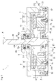
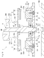
- FIG. 1 is a schematic cross-sectional view showing an outline of a motor according to Embodiment 1.
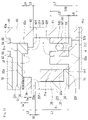
- FIG. FIG. 2 is a schematic cross-sectional view showing an enlarged area A of FIG.
- FIG. 3 is a cross-sectional schematic diagram showing another example of the region A in FIG. 1 in an enlarged manner.
- FIG. 4 is a schematic cross-sectional view showing an enlarged region B in FIG.
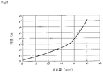
- FIG. 5 is a graph showing the relationship between the load on the inner race of the first bearing and the amount of displacement of the inner race with respect to the outer race of the first bearing.
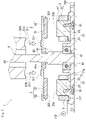
- 6A and 6B are diagrams illustrating a method for manufacturing the motor according to the first embodiment.
- 7A and 7B are diagrams for explaining a method for manufacturing the motor according to the first embodiment.
- FIG. 8 is a graph showing changes in induced voltage values.
- 9A is a schematic cross-sectional view for explaining the method of manufacturing the motor according to Embodiment 1.
- FIG. 9B is a schematic cross-sectional view illustrating the method for manufacturing the motor according to Embodiment 1.
- FIG. 9C is a schematic cross-sectional view illustrating the method for manufacturing the motor according to Embodiment 1.
- FIG. 9D is a schematic cross-sectional view illustrating the method for manufacturing the motor according to Embodiment 1.
- FIG. FIG. 10 is a schematic cross-sectional view for explaining a method of manufacturing a motor according to a modification.
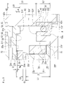
- FIG. 11 is a cross-sectional schematic diagram showing an enlarged area A of the motor according to the second embodiment.
- FIG. 12 is a cross-sectional schematic diagram showing another enlarged example of the area A of the motor according to the second embodiment.
- 13A and 13B are diagrams illustrating a method for manufacturing a motor according to the second embodiment.
- An object of the present disclosure is to provide a motor with excellent assembly accuracy. Another object of the present disclosure is to provide a method of manufacturing a motor that is excellent in manufacturability of the motor.
- the motor of the present disclosure has excellent assembly accuracy.
- the manufacturing method of the motor of the present disclosure is excellent in manufacturability of the motor of the present disclosure.
- Axial gap type motors are manufactured, for example, through two assembling steps of temporary assembly and final assembly of motor parts.
- the reason for temporarily assembling the parts is that it is difficult to make the length of the gap between the stator and the rotor the design length if the parts are assembled only once.
- the design gap length is a target value of the design gap length determined based on the motor specifications. Therefore, the length of the gap of the motor that is temporarily assembled is measured. A difference between the measured length of the gap obtained by measurement and the design length of the gap is obtained. After obtaining the measured length of the gap, disassemble the motor.
- the parts are assembled.
- a shim is placed between the bearing and the plate.
- the placement of the shim moves the bearing away from the plate by the thickness of the shim.
- the shaft supported by the bearings is displaced in the axial direction of the shaft.
- Misalignment of the shaft separates the rotor from the stator.
- the separation of the rotor causes the length of the gap to be longer than the measured length. That is, the length of the gap is longer than the measured length by the thickness of the shim. Since the thickness of the shim is the same as the above difference, the length of the gap can be the designed length.
- the parts are assembled twice, so the manufacturing work becomes complicated. Moreover, in the manufacturing method described above, the number of parts increases by the number of shims. Also, the use of shims may increase mechanical losses due to increased bearing preload.
- the inventors diligently studied a method of manufacturing a motor that does not use shims. As a result, the inventors have developed a manufacturing method that enables the length of the gap between the stator and rotor to be substantially the same as the design length in a single assembly of the parts.
- the embodiments of the present disclosure are listed and described.
- a motor includes a rotor; a stator arranged with a gap of design length in the rotational axis direction of the rotor; a shaft that is the rotation axis of the rotor; a bearing that rotatably supports the shaft, The rotor and the shaft or the shaft and the bearing are coupled by a press-fit structure.
- the above motor has excellent assembly accuracy. Since the rotor and the shaft are only connected by a press-fitting structure, the rotor can be moved in the axial direction of the shaft by applying a predetermined pressing force to the rotor along the axial direction of the shaft during the manufacturing process. Alternatively, since the shaft and the bearing are only connected by a press-fit structure, the shaft can be moved in the axial direction of the bearing by applying a predetermined pressing force to the shaft along the axial direction of the bearing during the manufacturing process. Therefore, the position of the rotor can be easily moved to a position where the length of the gap is the designed length.
- the rotor Since the rotor and the shaft are coupled by a press-fit structure, the rotor does not move in the axial direction of the shaft unless a predetermined pressing force is applied to the rotor along the axial direction of the shaft.
- the shaft and the bearing are coupled by a press-fit structure, the shaft does not move in the axial direction of the bearing unless a predetermined pressing force is applied to the shaft along the axial direction of the bearing. Therefore, the rotor is positioned at a position where the length of the gap is the designed length.
- the above motor does not have shims, it is possible to suppress an increase in the number of parts. Moreover, since the motor can suppress an increase in preload of the bearings, an increase in mechanical loss can be suppressed.
- the number of stators and the number of rotors may be one each.
- the above motor is of the single-stator/single-rotor type.
- the above motor has excellent assembly accuracy.
- the stator may include a stator core made of a powder compact.
- the above motor is excellent in assembly accuracy even when it is equipped with a stator core composed of a compacted body with lower dimensional accuracy than a stator core made of electromagnetic steel sheets.
- a method for manufacturing a motor includes: preparing parts for an axial gap type motor; comprising a step of assembling the parts,
- the parts are a rotor; a stator; a shaft that is the rotation axis of the rotor; a bearing that rotatably supports the shaft;
- determining a first mounting position or a second mounting position pressing the shaft into the rotor so as to be in the first mounting position or press-fitting the shaft into the bearing so as to be in the second mounting position;
- the first mounting position is a position where the length of the gap between the rotor and the stator is the design length among the positions of the rotor in the axial direction of the shaft
- the second mounting position is a position where the length of the gap is the design length among the positions of the bearing in the axial direction of the shaft.
- the method of manufacturing the motor includes the steps of determining the first mounting position and press-fitting the shaft into the rotor so that the determined first mounting position is obtained. can be positioned.
- the method for manufacturing the motor includes the step of obtaining the second mounting position and the step of press-fitting the shaft into the bearing so that the obtained second mounting position is obtained. Position can be positioned. Therefore, the above motor manufacturing method can set the length of the gap to the designed length by assembling the parts only once. Therefore, the above-described method for manufacturing a motor is excellent in manufacturability of a motor with excellent assembly accuracy without using shims.
- the step of determining the first mounting position or the second mounting position may determine the first mounting position or the second mounting position in consideration of the actual dimensions of the stator.
- the above motor manufacturing method can accurately determine the first mounting position or the second mounting position, so it is possible to manufacture a motor with excellent assembly accuracy.
- the stator is a stator core having a yoke and a plurality of teeth; a coil arranged on each of the plurality of teeth,
- the step of obtaining the first mounting position or the second mounting position may determine the first mounting position or the second mounting position based on an induced voltage value generated in the coil.
- the first mounting position or the second mounting position can be determined so that the torque of the motor always has a constant performance, so it is possible to manufacture a motor with small variations in torque.
- the step of determining the first mounting position or the second mounting position includes inserting a plate portion having the same thickness as the design length between the stator and the rotor, thereby determining the first mounting position or the second mounting position. position may be determined.
- the above motor manufacturing method can accurately determine the first mounting position or the second mounting position, so it is possible to manufacture a motor with excellent assembly accuracy.
- FIG. 1 is a sectional view of the motor 1 taken along a plane parallel to the axial direction of the shaft 4.
- a motor 1 illustrated in FIG. 1 is a single-stator/single-rotor axial gap motor.
- a single-stator/single-rotor motor is a motor in which the number of stators 2 and the number of rotors 3 are one each.
- An axial gap motor is a motor in which a stator 2 and a rotor 3 face each other with a gap in the axial direction of a shaft 4 .
- the motor 1 of this embodiment includes a stator 2 , a rotor 3 , a shaft 4 and a first bearing 51 .
- the motor 1 has a stator 2 , a rotor 3 and a shaft 4 housed in a case 7 .
- the stator 2 and the rotor 3 in the case 7 face each other with a gap in the axial direction of the shaft 4 .
- the length of this gap along the axial direction satisfies the design length G1.
- the design length G1 is a target value of the designed gap length determined based on the specifications of the motor 1 .
- the design length G1 has a certain allowable width.
- One of the features of the motor 1 of this embodiment is the fixing structure between the rotor 3 and the shaft 4 .
- the stator 2 is arranged on the first plane 71f of the case 7, as shown in FIG.
- the stator 2 includes a stator core 21 and a plurality of coils 25, as shown in FIG.
- the stator core 21 includes an annular plate-shaped yoke 22 and a plurality of columnar teeth 23 .
- the yoke 22 magnetically couples adjacent teeth 23 among the teeth 23 arranged in the circumferential direction of the yoke 22 .
- the yoke 22 has a planar first surface 22f, a planar second surface 22s, an outer peripheral surface, and an inner peripheral surface.
- the first surface 22f and the second surface 22s are surfaces connecting the outer peripheral surface and the inner peripheral surface.
- the first surface 22f is in contact with the first plane 71f.
- the second surface 22 s is a surface connected to the side surface of the tooth 23 .
- the teeth 23 are provided with coils 25 as shown in FIG.
- the number of teeth 23 is plural.
- Each tooth 23 is arranged at predetermined intervals in the circumferential direction of the yoke 22 .
- Each tooth 23 protrudes so as to be orthogonal to the second surface 22s of the yoke 22 shown in FIG.
- Each of the teeth 23 and the yoke 22 of the present embodiment are configured as an integrated compacted body.
- Each tooth 23 has the same shape and size.
- the shape of each tooth 23 is prismatic or cylindrical.
- Each tooth 23 has a side surface and an end surface 23a.
- the side surface is a surface connected to the second surface 22s of the yoke 22 .
- the end surface 23a is a surface connected to the side surface.
- the end surface 23a faces magnets 35 of the rotor 3, which will be described later.
- the stator core 21 has a hole as shown in FIG. A fastening member 91 is provided in this hole.
- the fastening member 91 fixes the stator core 21 to the first plane 71f.
- the fastening member 91 suppresses misalignment between the stator 2 and the first plane 71f.
- An example of the fastening member 91 is a screw or bolt.
- the hole is formed halfway through the tooth 23 from the first surface 22f.
- the number of holes may be less than the number of teeth 23 or may be the same as the number of teeth 23 .
- a compacted body that constitutes the stator core 21 is composed of an aggregate of a plurality of coated particles 24 shown in FIG. Coated particles 24 have metal particles 241 and insulating coatings 242 .
- the metal particles 241 are made of a soft magnetic material.
- Soft magnetic materials are pure iron or iron-based alloys.
- Pure iron has a purity of 99% or more. That is, pure iron has an iron (Fe) content of 99% by mass or more.
- the saturation magnetic flux density of pure iron is higher than that of iron-based alloys. Therefore, if the metal particles 241 of the powder compact are made of pure iron, the saturation magnetic flux density of the compact is likely to be improved. Also, the formability of pure iron is superior to iron-based alloys. Therefore, if the metal particles 241 of the compacted body are made of pure iron, the relative density of the compacted body tends to increase.
- An iron-based alloy is one that contains additional elements, with the balance being Fe and unavoidable impurities. Iron-based alloys contain the most Fe.
- the iron-based alloy is, for example, at least selected from the group consisting of Fe—Si (silicon) alloys, Fe—Al (aluminum) alloys, Fe—Si—Al alloys, and Fe—Ni (nickel) alloys. It is one kind.
- An example of Fe—Si based alloy is, for example, silicon steel.
- An example of the Fe--Si--Al alloy is, for example, sendust.
- An example of the Fe—Ni alloy is, for example, Permalloy.
- the electrical resistance of iron-based alloys is greater than that of pure iron.
- the iron-based alloy easily reduces iron loss such as eddy current loss. Therefore, if the metal particles 241 of the powder compact are made of an iron-based alloy, the loss of the powder compact can be easily reduced.
- the powder compact may contain both metal particles 241 composed of pure iron and metal particles 241 composed of an iron-based alloy.
- the insulating coating 242 covers the metal particles 241 .
- the insulating coating 242 can reduce iron loss such as eddy current loss.
- a powder compact provided with the insulating coating 242 tends to reduce loss.
- the material of the insulating coating 242 is, for example, oxide. Examples of oxides are phosphates, silica, magnesium oxide or aluminum oxide. Phosphate has excellent adhesion to the metal particles 241 and also has excellent deformability. Therefore, if the insulating coating 242 is made of phosphate, the insulating coating 242 is likely to deform following the deformation of the metal particles 241 in the process of producing the compact. Therefore, the insulating coating 242 is less likely to be damaged. Since the insulating coating 242 is less likely to be damaged, the loss of the powder compact can be easily reduced.
- the relative density of the compact may be 90% or more.
- a green compact having a relative density of 90% or more can easily improve the saturation magnetic flux density.
- a green compact having a relative density of 90% or more is likely to improve mechanical properties such as strength.
- the relative density may be 93% or higher, or even 95% or higher.
- the relative density may be 99% or less.
- a compacted body having a relative density of 99% tends to have a stable induced voltage value measured by the second method described later.
- “Relative density of the compact” refers to the ratio (%) of the actual density of the compact to the true density of the compact. That is, the relative density of the compact is obtained by [(actual density of compact/true density of compact) ⁇ 100].
- the actual density of the green compact is obtained by immersing the green compact in oil and impregnating the green compact with oil, [oil-impregnated density x (mass of green compact before oil impregnation / pressure after oil impregnation (Mass of powder compact)].
- the oil-impregnated density is (mass of compacted product after impregnated with oil/volume of compacted product after impregnated with oil).
- the actual density of the green compact can be determined by (mass of green compact before oil impregnation/volume of green compact after oil impregnation).
- the volume of the compacted body after impregnation with oil can typically be measured by a liquid displacement method.
- the true density of the powder compact is the theoretical density when voids are not included inside.
- Each coil 25 has a tubular portion.
- the cylindrical portion is configured by spirally winding a wire.
- the coil 25 of this embodiment is an edgewise wound coil.
- a covered rectangular wire is used for the winding of the coil 25 .
- Each coil 25 is arranged on the outer circumference of the side surface of the tooth 23 .
- the cross-sectional shape of the cylindrical portion of each coil 25 is, for example, a shape corresponding to the cross-sectional shape of the teeth 23 .
- the axial length of the cylindrical portion is slightly shorter than the length of the teeth 23 .
- FIG. 1 only the cylindrical portion is shown, and the illustration of both end portions of the winding is omitted.
- the rotor 3 is provided with a gap from the stator 2 .
- the rotor 3 comprises a rotor body 31 and at least one magnet 35 .
- the rotor body 31 is rotatably supported by the shaft 4 with respect to the case 7 .
- the rotor body 31 is an annular member.
- the rotor body 31 is provided with a through hole in the center.
- a second shaft portion 42 which will be described later, is press-fitted into this through hole.
- the rotor main body 31 and the second shaft portion 42 constitute a press-fit structure.
- the press-fit structure here means a structure in which the rotor main body 31 and the second shaft portion 42 are coupled by press-fit.
- a stress acts radially outward of the rotor body 31 on the inner peripheral surface of the rotor body 31 into which the second shaft portion 42 is press-fitted.
- the rotor body 31 Due to the press-fit structure, the rotor body 31 is positioned at a position where the length of the gap is the design length G1. The rotor body 31 does not move in the axial direction of the second shaft portion 42 unless a predetermined pressing force is applied to the second surface 31 s of the rotor body 31 , which will be described later. Therefore, when the motor 1 is used, the position of the rotor body 31 along the axial direction of the second shaft portion 42 does not shift. Since the rotor main body 31 and the second shaft portion 42 are only connected by a press-fit structure, if a predetermined pressing force is applied to the second surface 31s in the manufacturing process, the second shaft portion 42 can be moved along the axial direction. The rotor body 31 is moved.
- the position of the rotor body 31 along the axial direction of the second shaft portion 42 can be adjusted. Therefore, the length of the gap can be easily adjusted to the design length G1 in the manufacturing process.
- the press-fit structure tends to reduce the deflection of the rotor 3 .
- the rotor body 31 can be pulled out from the second shaft portion 42 by applying a predetermined pressing force to the rotor body 31 in the axial direction of the second shaft portion 42 .
- the diameter of the through hole of the rotor body 31 at the fitting portion is smaller than the outer diameter of the second shaft portion 42 .
- the rotor body 31 has a first surface 31f, a second surface 31s, an inner peripheral surface and an outer peripheral surface.
- the first surface 31f and the second surface 31s connect the inner peripheral surface and the outer peripheral surface.
- the first surface 31f is a surface facing the stator 2 .
- the second surface 31s is a surface facing the second bearing 55 shown in FIG. The second bearing 55 will be described later.
- a concave portion 32 is provided on the first surface 31f of the present embodiment.
- the recess 32 opens toward the stator 2 .
- a magnet 35 is fixed to the bottom surface 32 a of the recess 32 .
- the inner peripheral surface of the rotor body 31 is in contact with the second shaft portion 42 of the shaft 4 .
- the outer peripheral surface of the rotor body 31 is not in contact with the inner peripheral surface of the peripheral wall portion 73 of the case 7, as shown in FIG. A space is provided between the outer peripheral surface of the rotor body 31 and the inner peripheral surface of the peripheral wall portion 73 of the case 7 .
- the number of magnets 35 may be one or plural. If the number of magnets 35 is one, compared with the case where the number of magnets 35 is plural, the number of parts is small and the rotor 3 is easy to manufacture. Therefore, it is easy to improve the manufacturability of the motor 1 . Moreover, it is easy to manufacture the motor 1 with excellent assembly accuracy.
- the shape of the magnets 35 is annular.
- One sheet of magnet 35 has S poles and N poles alternately arranged in the circumferential direction.
- the specific number of magnets 35 is the same as the number of teeth 23 .
- the plurality of magnets 35 are arranged at regular intervals in the circumferential direction of the rotor body 31 .
- the shape of each magnet 35 is, for example, a flat plate shape.
- the planar shape of each magnet 35 is the same as the planar shape of the end face 23a of the tooth 23, for example.
- Each magnet 35 is magnetized in the axial direction of the rotating shaft of the rotor 3 .
- the magnetization directions of the magnets 35 adjacent to each other in the circumferential direction of the rotor body 31 are opposite to each other.
- the magnet 35 repeats attraction and repulsion with respect to each tooth 23 by the rotating magnetic field generated by the stator 2 , thereby rotating the rotor 3 .
- the magnet 35 is a permanent magnet.
- permanent magnets are ferrite magnets, neodymium magnets, samarium-cobalt magnets, or bonded magnets.
- neodymium magnets and samarium-cobalt magnets have strong magnetic forces.
- a shaft 4 is a rotating shaft of the rotor 3 .
- the shaft 4 is composed of a solid round bar-shaped body.
- the shaft 4 has a plurality of shaft portions with different outer diameters, as shown in FIG.
- the plurality of shaft portions are configured integrally.
- the shaft 4 of the present embodiment includes a first shaft portion 41, a second shaft portion 42, a third shaft portion 43, and a fourth shaft in order from the first plate portion 71 to the second plate portion 72 of the case 7. It has a portion 44 .
- the first shaft portion 41 is provided inside the first bearing 51 as shown in FIG.
- the outer peripheral surface of the first shaft portion 41 is in contact with the inner peripheral surface of the inner race 52 of the first bearing 51, as shown in FIG.
- the second shaft portion 42 is a portion press-fitted into the through hole of the rotor body 31 .
- the outer peripheral surface of the second shaft portion 42 is in contact with the inner peripheral surface of the rotor body 31 .
- a stress acts on the outer peripheral surface of the second shaft portion 42 in a direction toward the center of the second shaft portion 42 .
- the second shaft portion 42 of this embodiment has a uniform outer diameter in the axial direction of the shaft 4 .
- the outer peripheral surface of the second shaft portion 42 may be tapered toward the third shaft portion 43 .
- the surface of the portion of the second shaft portion 42 that fits with the rotor body 31 may be knurled.
- the second shaft portion 42 has an outer diameter larger than that of the first shaft portion 41, as shown in FIG.
- the second shaft portion 42 has a first end surface 42f and a second end surface 42s.
- the first end surface 42 f contacts the first end surface 52 f of the inner race 52 .
- the first end face 42f is not in contact with the outer race 53 of the first bearing 51.
- the second end face 42 s contacts the first end face of the inner race 56 of the second bearing 55 .
- the second end surface 42 s does not contact the outer race 57 of the second bearing 55 .
- the third shaft portion 43 is provided inside the second bearing 55 .
- the outer peripheral surface of the third shaft portion 43 is in contact with the inner peripheral surface of the inner race 56 .
- the third shaft portion 43 has an outer diameter smaller than the outer diameter of the second shaft portion 42 .
- the fourth shaft portion 44 is provided inside the through hole 72h as shown in FIG. 72 h of through-holes are provided in the 2nd plate part 72 mentioned later.
- the fourth shaft portion 44 has an outer diameter smaller than the outer diameter of the third shaft portion 43 .
- the first bearing 51 and the second bearing 55 rotatably support the shaft 4 as shown in FIG.
- the first bearing 51 is attached to the first shaft portion 41 .
- the second bearing 55 is attached to the third shaft portion 43 .
- the configurations of the first bearing 51 and the second bearing 55 may be the same configuration as each other, or may be different configurations.
- the first bearing 51 is a radial bearing having an inner race 52 and an outer race 53, as shown in FIGS.
- the radial bearing of this embodiment is a ball bearing in which balls 54 are arranged between an inner race 52 and an outer race 53 .
- the inner peripheral surface of the inner race 52 is in contact with the outer peripheral surface of the first shaft portion 41 .
- the outer peripheral surface of the outer race 53 is in contact with a projecting portion 71a, which will be described later.
- the inner race 52 has a first end face 52f and a second end face 52s.
- the outer race 53 has a first end face 53f and a second end face 53s.
- the first end surface 52f is in contact with the first end surface 42f.
- the first end surface 53f is not in contact with the shaft 4.
- the second end face 52s is not in contact with the case 7.
- the second end face 52s is in contact with a fixing member (not shown). This fixing member mechanically fixes the first bearing 51 and the first shaft portion 41 .
- this fixing member is a retaining ring or a shaft nut.
- a shaft nut is used as the fixing member, it is preferable to form a threaded portion on the outer peripheral surface of the first shaft portion 41 .
- This fixing member may not be used. In that case, the inner race 52 and the first shaft portion 41 are fixed by being fitted together.
- the second end face 53s is in contact with the first plane 71f.
- FIG. 2 shows an example in which the first end face 52f and the first end face 53f are not shifted along the axial direction of the first bearing 51.
- FIG. 3 shows an example in which the first end face 52f and the first end face 53f are shifted along the axial direction of the first bearing 51.
- the first end surface 52f and the first end surface 53f may be displaced along the axial direction of the first bearing 51 .
- the configuration of the second bearing 55 is the same as that of the first bearing 51. That is, the second bearing 55 is a radial bearing having an inner race 56 and an outer race 57, as shown in FIGS.
- the inner peripheral surface of the inner race 56 is in contact with the outer peripheral surface of the third shaft portion 43 .
- the outer peripheral surface of the outer race 57 is in contact with the inner peripheral surface of the recess 72a.
- the recess 72 a is provided in the second plate portion 72 .
- Each of the inner race 56 and the outer race 57 has a first end face and a second end face.
- the first end surface of the inner race 56 is in contact with the second end surface 42s.
- a second end surface of the inner race 56 is not in contact with the elastic member 8 and the case 7, which will be described later.
- the second end face of the inner race 56 may be in contact with a fixed member similar to the first bearing 51, or may not be in contact with the fixed member. This is because the outer race 57 is pressed in the direction toward the rotor 3 by the elastic member 8 . A first end face of the outer race 57 is not in contact with the rotor 3 and the shaft 4 . A second end face of the outer race 57 is in contact with the elastic member 8 shown in FIG.
- At least one of the first bearing 51 and the second bearing 55 may be an angular ball bearing, unlike the present embodiment.
- the elastic member 8 presses the second bearing 55 toward the rotor 3 .
- the elastic member 8 is arranged between the outer race 57 and the bottom of the recess 72a.
- An example of the elastic member 8 is a spring washer, a disc spring washer, a corrugated washer, or a rubber O-ring.
- the case 7 accommodates the stator 2, the rotor 3, a portion of the shaft 4, the first bearing 51, and the second bearing 55 inside.
- the case 7 includes a first plate portion 71 , a second plate portion 72 and a peripheral wall portion 73 .
- the peripheral wall portion 73 and the second plate portion 72 of this embodiment are integrally formed.
- the peripheral wall portion 73 and the first plate portion 71 of the present embodiment are configured separately.
- the peripheral wall portion 73 and the first plate portion 71 may be configured integrally, and the peripheral wall portion 73 and the second plate portion 72 may be configured separately.
- the peripheral wall portion 73, the first plate portion 71, and the second plate portion 72 may be configured separately.
- the peripheral wall portion 73 and the first plate portion 71 of this embodiment are fixed to each other by a fastening member 92 .
- An example of the fastening member 92 is, like the fastening member 91, a screw or bolt.
- the peripheral wall portion 73 surrounds the outer peripheries of the stator 2 and the rotor 3 .
- a hole is provided in the end surface of the peripheral wall portion 73 .
- a fastening member 92 is provided in this hole.
- the first plate portion 71 has a first flat surface 71f, a projecting portion 71a, a first through hole, a second through hole, and a third through hole.
- the first plane 71f is provided inside the case 7.
- the stator 2 is arranged on the first plane 71f.
- the projecting portion 71 a is provided between the stator 2 and the first bearing 51 .
- the shape of the projecting portion 71a is, for example, cylindrical.
- the projecting portion 71a is connected to the first plane 71f.
- the inner peripheral surface of the projecting portion 71 a is in contact with the outer peripheral surface of the outer race 53 .
- the projecting portion 71 a can be used for positioning the first bearing 51 .
- the outer peripheral surface of the projecting portion 71a may or may not be in contact with the inner peripheral surface of the yoke 22 .
- a part of the first shaft portion 41 is provided in the first through hole.
- a fastening member 91 is provided in the second through hole.
- the second through hole is provided at a portion of the stator core 21 corresponding to the hole portion.
- a fastening member 92 is provided in the third through hole.
- the third through hole is provided at a portion of the peripheral wall portion 73 corresponding to the hole portion.
- the second plate portion 72 has a recess 72a in the center.
- a through hole 72h is provided at the bottom of the recess 72a.
- a fourth shaft portion 44 is provided in the through hole 72h.
- the inner diameter of the through hole 72 h is larger than the outer diameter of the fourth shaft portion 44 . Therefore, the shaft 4 rotates without contacting the inner peripheral surface of the through hole 72h and the fourth shaft portion 44 .
- the motor 1 of this embodiment has excellent assembly accuracy. Since the second shaft portion 42 is only press-fitted into the rotor 3, if a predetermined pressing force is applied to the rotor 3 along the axial direction of the second shaft portion 42 in the manufacturing process, the axial direction of the second shaft portion 42 can be adjusted. to move the rotor 3. Therefore, the position of the rotor 3 can be easily moved to the position where the length of the gap is the designed length G1. Since the second shaft portion 42 is press-fitted into the rotor 3 , the rotor 3 will move in the axial direction of the second shaft portion 42 unless a predetermined pressing force is applied to the rotor 3 along the axial direction of the second shaft portion 42 . does not move. Therefore, the rotor 3 is positioned at a position where the length of the gap is the designed length G1.
- the manufacturing method of the motor according to the present embodiment includes a process A and a process B. As shown in FIG. Process A prepares the parts of the motor. Process B assembles the parts.
- the parts prepared in step A are the parts of the motor 1 described above with reference to FIG.
- the parts include stator 2 , rotor 3 , shaft 4 , first bearing 51 , second bearing 55 , case 7 , elastic member 8 , fastening member 91 and fastening member 92 .
- the rotor 3 before assembly includes a rotor body 31 having an inner diameter smaller than the outer diameter of the second shaft portion 42 of the shaft 4, as shown in FIG. That is, the second shaft portion 42 before assembly has an outer diameter larger than the inner diameter of the rotor body 31 .
- a corner portion between the outer peripheral surface of the second shaft portion 42 and the second end surface 42s is chamfered.
- press-fitting is used in the sense normally used as a fitting method between a hole and a shaft.
- Press-fitting is a method in which the outside diameter of the hole before press-fitting is several tens of micrometers smaller than the outside diameter of the shaft, and the fitting is performed by applying pressure.
- the dimensional difference between the hole and the shaft can comply with commonly used fit tolerances.
- the press-fitting pressure is not limited as long as it is a force normally used according to the material and fitting tolerance.
- the corner between the inner peripheral surface of the rotor body 31 and the first surface 31f may also be chamfered.
- step B of assembling the parts each member is fixed at a predetermined position.
- the motor 1 as shown in FIG. 1 is manufactured.
- steps B1 to B6 are performed in order.
- step B ⁇ b>1 a combination of the first plate portion 71 , the stator 2 , the first bearing 51 and the fastening member 91 is placed on the pedestal 700 .
- the stator 2 placed on the first plane 71f and the first plate portion 71 are fixed by the fastening member 91 .
- the fastening member 91 is provided in the second through hole of the first plate portion 71 and the hole portion of the stator 2 .
- a first bearing 51 is arranged on the first plane 71f.
- step B ⁇ b>2 the first shaft portion 41 is placed inside the first bearing 51 .
- step B ⁇ b>3 the second shaft portion 42 is press-fitted into the rotor 3 .
- the second shaft portion 42 is press-fitted into the rotor 3 by pressing the second surface 31s of the rotor body 31 with a punch 500 of a press-fitting machine, which will be described later.
- a hollow arrow in FIG. 6 indicates the pressing direction of the punch 500 .
- the second bearing 55 is arranged on the third shaft portion 43 .
- the elastic member 8 is arranged on the second bearing 55.
- the fourth shaft portion 44 is fitted into the through hole 72h of the second plate portion 72, and the end face of the peripheral wall portion 73 and the first plate portion 71 are butted against each other. Then, the first plate portion 71 and the peripheral wall portion 73 are fixed by the fastening member 92 .
- the fastening member 92 is provided in the third through hole of the first plate portion 71 and the hole portion of the peripheral wall portion 73 .
- the shape of the punch 500 is cylindrical.
- the inner diameter of the punch 500 is larger than the outer diameter of the second shaft portion 42 .
- An annular end surface 510 of the punch 500 may be provided with a recess 511 .
- the number of recesses 511 may be singular or plural.
- the shape of the single recess 511 is, for example, an annular shape.
- the plurality of recesses 511 are provided at predetermined intervals in the circumferential direction of the end surface 510 .
- the second surface 31 s of the rotor body 31 may be provided with the convex portion 311 .
- the protrusion 311 fits into the recess 511 .
- a convex portion may be provided on the end surface 510 and a concave portion may be provided on the second surface 31s.
- step B3 the following steps B31 and B32 are performed.
- a step B31 obtains a first mounting position.
- the first attachment position is the position of the rotor 3 in the axial direction of the second shaft portion 42 where the length of the gap is the design length G1.
- the second shaft portion 42 is press-fitted into the rotor 3 so as to be at the obtained first mounting position.
- a first method is a method of determining the first mounting position in consideration of the actual dimensions of the stator 2 .
- the actual size of the stator 2 is the size of the stator 2 actually measured before assembly. Consideration of the actual dimensions includes consideration of the actual dimensions themselves and consideration of calculated values obtained from the actual dimensions.
- the calculated value obtained from the actual dimensions is, for example, the average value of the actual dimensions of each stator 2 obtained from a plurality of stators 2 .
- the number of measurements for obtaining the average value may be less than the number of motors 1 manufactured. For example, assume that 1000 motors 1 are manufactured. If one stator 2 is used for one motor 1, less than 1000 measurements should be taken to find the average value of the actual dimensions of the part. Even if two stators 2 are used, the number of measurements for obtaining the average value of the actual dimensions of the part should be less than 1000. More specifically, the average value is obtained from the actual dimensions of 50 or less stators 2 . The average value may be obtained for each stator 2 lot.
- the actual size of the stator 2 is the actual size of the length L1 of the stator core 21 shown in FIG.
- the actual dimension of the length L1 is obtained from the actual dimension of the length between the first surface 22f of the yoke 22 and the end surface 23a of the tooth 23.
- the actual length between the first surface 22f and the end surface 23a can be measured using a height gauge equipped with a grade 0 surface plate.
- the stator core 21 is placed on the surface plate so that the end surface 23a faces upward.
- a plurality of measurement points are selected on the end surface 23a.
- the measurement point is set on a straight line drawn so as to pass through the center of gravity of the end surface 23 a and the center of the yoke 22 in a plan view of the stator core 21 , for example. Three or more measurement points may be selected on the straight line.
- the measurement points may include the center of gravity of the end face 23a, the edge of the end face 23a near the center of the yoke 22, and the edge of the end face 23a far from the center of the yoke 22 on the straight line.
- the length between the first surface 22f and the end surface 23a is the average value of the lengths of the straight lines that connect the surface plate and each measurement point among the straight lines perpendicular to the surface plate.
- the actual dimension of the stator 2 may be the actual length between the first plane 71f and the end surface 23a.
- the actual length between the first plane 71f and the end surface 23a is obtained in the same manner as the actual length between the first surface 22f and the end surface 23a. That is, the first plate portion 71 is placed on the surface plate, and the stator core 21 is placed on the first plate portion 71 .
- the measurement points are the same as those for measuring the actual length between the first surface 22f and the end surface 23a.
- the first mounting position is a position where the length from the first surface 22f to the first end surface 35f is "actual dimension of stator 2+design length G1".
- the length which the rotor 3 moves toward the first axial part 41 along the axial direction of the second axial part 42 from 42 s of second end surfaces to a first attachment position be the 1st movement length L01.
- the rotor 3 can be moved by pressing the second surface 31 s of the rotor body 31 with the punch 500 .
- the first moving length L01 is the length from the second end surface 42s to the first end surface 35f when the length from the first surface 22f or the first flat surface 71f to the first end surface 35f is "the actual dimension of the stator 2 + the design length G1". It is the length up to the surface 31f.
- the first moving length L01 is obtained by "(length L2+length L3)-(actual dimension of length L1+design length G1+length L5-length L4)".
- Length L2 is the height of first bearing 51 .
- a length L3 is the length of the second shaft portion 42 . That is, the length L3 is the length between the first end surface 42f and the second end surface 42s.
- Length L4 is the depth of recess 32 . That is, the length L4 is the length between the first surface 31f and the bottom surface 32a.
- Length L5 is the thickness Tm of magnet 35 . When the magnet 35 and the rotor body 31 are fixed with the adhesive 38, the length L5 is the sum of the thickness Tm of the magnet 35 and the thickness Ta of the adhesive 38.
- All of these lengths are lengths along the axial direction of the shaft 4.
- All of length L2 to length L5 are design dimensions and are known.
- the difference between the actual dimension and the design dimension of the length L2 to the length L5 tends to be smaller than the difference between the actual dimension and the design dimension of the length L1.
- the difference between the actual dimension of the length L1 and the design dimension tends to become large particularly when the stator core 21 is made of a compacted body. Therefore, the first mounting position, that is, the first movement length L01, needs to consider the actual dimension of the length L1.
- the first mounting position ie the first movement length L01, may take into account at least one actual dimension from length L2 to length L5.
- the actual size of the length L2 may be either the actual height of the inner race 52 or the actual height of the outer race 53.
- the actual height of the outer race 53 is easier to measure than the actual height of the inner race 52 .
- the actual height of the inner race 52 or the actual height of the outer race 53 is the average value of heights at a plurality of measurement points. Measurement points are taken at equal intervals in the circumferential direction of the inner race 52 or the outer race 53 .
- the number of measurement points shall be 3 or more.
- the actual dimension of length L3 is the average value of lengths at multiple measurement points.
- the measurement points are taken at regular intervals in the circumferential direction of the second shaft portion 42 .
- the number of measurement points shall be 3 or more.
- the actual dimension of length L4 is the average value of depths at multiple measurement points. Measurement points are taken at equal intervals on the circumference of three concentric circles.
- the three circumferences refer to the circumference of the inner peripheral edge of the recess 32, the circumference of the outer peripheral edge of the recess 32, and the middle point between the inner peripheral edge and the outer peripheral edge of the recess 32 when viewed from above. Circumferential.
- the number of measurement points on each circumference shall be 3 or more.
- a measurement point on the circumference of the inner peripheral edge, a measurement point on the circumference of the outer circumference, and a measurement point on the circumference of the intermediate point are located on a straight line along the radial direction of the rotor 3. .
- the depth of each measurement point is the length along the axial direction of the rotor 3 between each measurement point and the first surface 31 f of the rotor body 31 .
- the actual dimension of the length L5 is the average value of the thicknesses Tm of the plurality of magnets 35 when the number of magnets 35 is plural.
- Each thickness Tm may be the thickness at one measurement point, or may be the average value of the thicknesses Tm at a plurality of measurement points.
- One measurement point is the center of gravity of the first end face 35f when the magnet 35 is viewed from above.
- a plurality of measurement points are set on a straight line drawn so as to pass through the center of gravity of the first end surface 35 f and the center of the rotor 3 in plan view of the magnet 35 . Three or more measurement points may be taken on the straight line.
- the plurality of measurement points are the center of gravity of the first end face 35f, the edge of the first end face 35f near the center of the rotor 3, and the edge of the first end face 35f far from the center of the rotor 3 on the straight line. , may be included.
- the thickness Tm of each magnet 35 is the average value of the length along the axial direction of the rotor 3 at each measurement point.
- the actual dimension of the length L5 is the average value of the thicknesses Tm at a plurality of measurement points.
- Measurement points are taken at equal intervals on the circumference of three concentric circles.
- the three circumferences are the circumference of the inner circumference of the first end face 35f, the circumference of the outer circumference of the first end face 35f, and the inner circumference and the outer circumference of the first end face 35f. It shall be on the circumference of the midpoint to the rim.
- the number of measurement points on each circumference shall be 3 or more.
- a measurement point on the circumference of the inner peripheral edge, a measurement point on the circumference of the outer circumference, and a measurement point on the circumference of the intermediate point are located on a straight line along the radial direction of the rotor 3. .
- the thickness at each measurement point is the length along the axial direction of the rotor 3 at each measurement point.
- the actual dimension of the length L5 is the actual dimension when the rotor body 31 and the magnet 35 are fixed when the adhesive 38 is provided. That is, the actual dimension of the length L5 is the average of the length along the axial direction of the rotor 3 between the measurement point of the thickness Tm of the magnet 35 and the bottom surface 32a of the concave portion 32 described above.
- the first mounting position may also be obtained by considering the displacement amount g of the first bearing 51 shown in FIG.
- the shift amount g is the length along the axial direction of the first bearing 51 between the first end surface 53f and the first end surface 52f.
- the amount of deviation g is determined by considering the load acting on the inner race 52 due to the weight of the shaft 4 and the rotor 3 and the load acting on the inner race 52 due to the attraction of the magnet 35 to the stator 2 . Further, the deviation amount g acts on the inner race 52 due to the load acting on the inner race 52 due to the weight of the second bearing 55 and the pressing force of the elastic member 8 pressing the second bearing 55 toward the first bearing 51 . It is obtained by considering at least one of the load.
- a load due to the weight of the shaft 4 and the rotor 3 and a load due to the attraction of the magnet 35 to the stator 2 are mainly applied to the inner race 52 .
- At least one of the load due to the weight of the second bearing 55 and the load due to the pressing force of the elastic member 8 pressing the second bearing 55 toward the first bearing 51 acts on the inner race 52 .
- the first end surface 52f may be displaced from the first end surface 53f.
- the displacement of the first end surface 52f is greatly affected by the attractive force of the magnet 35. As shown in FIG. That is, the stronger the magnetic force of the magnet 35, the more the first end surface 52f is displaced.
- the length of the gap is shorter than the design length G1 by the amount of deviation g. In that case, the shift amount g is taken into consideration.
- the amount of deviation g can be obtained from a graph such as that shown in FIG.
- the load (N) on the vertical axis in FIG. 5 indicates the load applied to the inner race 52 of the first bearing 51 .
- the graph in FIG. 5 should be prepared in advance. Specifically, the graph of FIG. 5 can be obtained by applying the load in the axial direction of the first bearing 51 to the inner race 52 while displacing it.
- the first mounting position is a position where the length from the first surface 22f to the first end surface 35f is "actual dimension of stator 2+design length G1+shift amount g".
- the first moving length L01 is obtained by "(length L2+length L3)-(actual dimension of length L1+design length G1+length L5-length L4)-shift amount g".
- the second method is to determine the first attachment position based on the induced voltage value generated in the coil 25, as shown in FIG.
- FIG. 7 shows the state before the second shaft portion 42 is press-fitted into the rotor body 31 .
- the induced voltage value can be measured by the voltmeter 110.
- FIG. 7 The induced voltage value decreases as the gap length increases, and increases as the gap length decreases.
- a target value of the design induced voltage value determined based on the specifications of the motor 1 is set as a design voltage value.
- the design voltage value has a certain allowable range.
- the gap length based on this design voltage value is the design length G1.
- Procedure 1 and Procedure 2 are performed in order.
- Procedure 1 moves the rotor 3 toward the first shaft portion 41 along the axial direction of the second shaft portion 42 .
- the moving length of the rotor 3 in Procedure 1 can be selected as appropriate.
- Procedure 2 measures the induced voltage value. The induced voltage value may be measured without moving the rotor 3 along the axial direction of the second shaft portion 42, or may be measured while moving the rotor 3 along the axial direction of the second shaft portion 42. good too.
- step 1 When the induced voltage value is measured without moving the rotor 3 along the axial direction of the second shaft portion 42, in step 1, the pressing force is applied to the rotor body 31 after moving the rotor 3 by a predetermined length. stop. After that, perform step 2. Procedures 1 and 2 are repeated until the measured induced voltage value satisfies the design voltage value.
- the graph in FIG. 8 shows, as an example, the case where procedure 1 and procedure 2 are performed four times.
- the induced voltage value (V) on the vertical axis on the left side of FIG. 8 is the induced voltage value when the rotor 3 is moved to a predetermined position by procedure 1.
- FIG. The length of the gap on the vertical axis on the right side of FIG. 8 is the length of the gap when the rotor 3 is moved to a predetermined position according to procedure 1.
- the number of times on the horizontal axis in FIG. 8 is the number of times that procedure 1 and procedure 2 were performed.
- the movement length of the rotor main body 31 increases as the number of times the procedure 1 is performed increases. As the number of times increases, the measured induced voltage value increases as shown in FIG.
- the gap length becomes shorter as the moving length of the rotor body 31 becomes longer.
- the procedure 1 and the procedure 2 are performed one to three times, the induced voltage value does not satisfy the range of the design voltage value.
- the induced voltage value satisfies the design voltage value range. That is, in the example shown in FIG. 8, the gap length becomes the design length G1 by performing the procedure 1 and the procedure 2 four times.
- the induced voltage value rises continuously, not stepwise as shown in FIG.
- the following procedure should be performed.
- the shaft 4 is pulled out from the first bearing 51.
- the rotor body 31 is moved toward the third shaft portion 43 . Then, the above-described step B2 and subsequent steps are performed again.
- the design voltage value may be a value that takes into consideration the deviation amount g of the first bearing 51 shown in FIG.
- the design voltage value is the induced voltage value when the gap length is the sum of the design length G1 when the first bearing 51 does not shift and the shift amount g.
- a third method is to determine the first mounting position by sandwiching the plate portion 120 between the stator 2 and the rotor 3, as shown in FIGS. 9A to 9D.
- the plate portion 120 is a flat plate.
- the plate portion 120 is composed of a plurality of split pieces 121 .
- the number of split pieces 121 can be selected as appropriate.
- the plurality of split pieces 121 may be split only in the circumferential direction, or may be split in both the circumferential direction and the thickness direction.
- the plate portion 120 has the same thickness as the design length G1.
- the thickness of the plate portion 120 is the thickness of the split pieces 121 .
- the thickness of the plate portion 120 is the total thickness of the plurality of split pieces 121 stacked.
- the plurality of split pieces 121 are split only in the circumferential direction.
- the number of split pieces 121 in this embodiment is two.
- the shape of each split piece 121 is semicircular in this embodiment.
- a through-hole in which the shaft 4 is arranged is provided in the center of the plate portion 120 when the split pieces 121 are combined to form an annular shape.
- the inner diameter of the plate portion 120 is larger than the largest outer diameter of the shaft 4 .
- the outer diameter of plate portion 120 is larger than the outer diameter of rotor 3 . This plate portion 120 is used as follows.
- the plate portion 120 is placed on the end face 23a of the tooth 23.
- the timing at which the plate portion 120 is placed on the end surface 23 a may be before the second shaft portion 42 is press-fitted into the rotor body 31 or after the second shaft portion 42 is press-fitted into the rotor body 31 . If it is after press-fitting, the plate portion 120 is placed on the end surface 23a in a state where the gap length is longer than the design length G1.
- FIG. 9A shows an example in which each split piece 121 is placed on the end surface 23a by moving the split pieces 121 radially inwardly from the outer side of the stator 2, as indicated by the white arrows.
- the second shaft portion 42 is press-fitted into the rotor body 31 .
- the rotor body 31 is moved until the first end face 35f of the magnet 35 and the plate portion 120 come into contact with each other.
- the pressing force applied to the rotor body 31 is stopped.
- the timing of stopping the application of the pressing force is, for example, when the load of the punch 500 exceeds a predetermined value.
- the application of the pressing force may be stopped at the time when a piezoelectric plate is placed between the plurality of split pieces 121 stacked in the thickness direction and the piezoelectric plate detects a predetermined load and transmits a signal.
- the thickness of the piezoelectric plate and the plate portion 120 is adjusted so that the total thickness of the piezoelectric plate and the plate portion 120 is the same as the design length G1.
- the plate portion 120 is removed from between the first end face 35f and the end face 23a.
- Each split piece 121 is moved radially outward as indicated by the white arrow.
- Lifting the shaft 4 together with the rotor 3 makes it easier to remove the plate portion 120 .
- the rotor body 31 is positioned on the second shaft portion 42 by press fitting, the rotor body 31 does not shift in the axial direction of the second shaft portion 42 even when the shaft 4 is lifted.
- the plate portion 120 can be easily pulled out from between the magnet 35 and the teeth 23 .
- the split piece 121 sandwiched between the split pieces 121 at both ends in the thickness direction should be removed first. This is because damage to the first end face 35f and the end face 23a due to sliding contact between the first end face 35f and the end face 23a and the split piece 121 is easily suppressed.
- the thickness of the plate portion 120 should be set in consideration of the displacement amount g of the first bearing 51 shown in FIG.
- the thickness of the plate portion 120 is the total thickness of the design length G1 when the first bearing 51 does not shift and the amount of shift g.
- the first end surface and the second end surface of the plate portion 120 may be mirror surfaces.
- a coating layer (not shown) may be provided on the first end face and the second end face of the plate portion 120 .
- the first end surface of the plate portion 120 is the surface that contacts the first end surface 35 f of the magnet 35 .
- the second end surface of plate portion 120 is a surface that contacts end surface 23 a of tooth 23 .
- the coating layer is fluororesin.
- a specific example of the fluororesin is Teflon (registered trademark).
- the first mounting position of the rotor 3 having the design length G1 can be obtained before assembling the parts.
- the first attachment position of the rotor 3 having the design length G1 can be determined while assembling the parts. Therefore, in the motor manufacturing method of the present embodiment, the length of the gap can be set to the design length G1 by assembling the parts only once. Therefore, the motor manufacturing method of the present embodiment is excellent in productivity of the motor 1 with excellent assembly accuracy without using shims.
- the inner race 52 may be displaced with respect to the outer race 53 of the first bearing 51.
- the method of manufacturing the motor according to the present embodiment can determine the first mounting position of the rotor 3 in consideration of the above-described shift amount g. Therefore, even if the inner race 52 is misaligned, the motor manufacturing method of the present embodiment is excellent in the productivity of the motor 1 with excellent assembly accuracy.
- the motor manufacturing method of the present embodiment is excellent in manufacturability of a plurality of motors 1 with excellent assembly accuracy even when the process of assembling parts is repeated. Therefore, the motor manufacturing method of the present embodiment can manufacture a plurality of motors 1 with small variations in performance.
- the first mounting position of the rotor 3 is obtained in consideration of the average value of the actual dimensions of the stator 2, which is smaller than the number of manufactures, The manufacturability of the motor 1 can be easily improved as compared with the case where one mounting position is obtained.
- FIG. 10 shows a state in which the pedestal 700 and the first plate portion 71 are separated for convenience of explanation.
- the base 700 has a cylindrical recess 710.
- At least one protrusion 711 is provided on the inner peripheral surface of the recess 710 .
- the protrusion 711 protrudes toward the center of the recess 710 .
- the protrusions 711 are provided at regular intervals in the circumferential direction of the recess 710 .
- the first shaft portion 41 of the shaft 4 has a length that fits in the recess 710 .
- a slit portion 411 is provided on the outer peripheral surface of the first shaft portion 41 .
- a protrusion 711 is fitted in the slit portion 411 .
- Rotation of the shaft 4 is suppressed by fitting the projection 711 into the slit portion 411 .
- the second surface 31s can be pressed by the punch 500 while the rotation of the shaft 4 is suppressed. Therefore, the pressing operation of the rotor main body 31 can be easily performed.
- a slit portion may be provided on the inner peripheral surface of the concave portion 710 and a projection may be provided on the outer peripheral surface of the first shaft portion 41 .
- a capacitor having a thickness equal to or less than the design length G1 of the gap between the end surface 23a of the tooth 23 and the first end surface 35f of the magnet 35 it is also considered to install a capacitor having a thickness equal to or less than the design length G1 of the gap between the end surface 23a of the tooth 23 and the first end surface 35f of the magnet 35, and measure the potential to estimate the length of the gap. be done.
- the capacitor since the capacitor may be non-contact, deterioration of the capacitor due to wear does not occur, and quality maintenance of the measuring device is facilitated.
- FIG. 2 differs from the motor 1 of Embodiment 1 in that the shaft 4 and the first bearing 51 are coupled by a press-fitting structure.
- the following description will focus on the differences from the motor 1 of the first embodiment. Descriptions of configurations similar to those of the motor 1 of the first embodiment may be omitted.
- the rotor body 31 and the shaft 4 are combined by press-fitting the shaft 4 into the through hole of the rotor body 31 .
- the position of the rotor body 31 along the axial direction of the shaft 4 is such that the rotor body 31 abuts against a second end surface 42s of a second shaft portion 42 of the shaft 4, which will be described later. It is positioned by
- the shaft 4 has a first shaft portion 41, a second shaft portion 42, a third shaft portion 43, a fourth shaft portion 44, and a 13 has a fifth shaft portion 45 .
- the first shaft portion 41 is provided inside the first bearing 51 as shown in FIG.
- the outer peripheral surface of the first shaft portion 41 is in contact with the inner peripheral surface of the inner race 52 of the first bearing 51 .
- the second shaft portion 42 has a diameter larger than that of the first shaft portion 41 .
- the diameter of the second shaft portion 42 is larger than the inner diameter of the rotor body 31 .
- a first end surface 42 f of the second shaft portion 42 is not in contact with the first bearing 51 .
- a second end surface 42 s of the second shaft portion 42 is in contact with the first surface 31 f of the rotor body 31 .
- the third shaft portion 43 is provided in the through hole of the rotor body 31.
- the outer peripheral surface of the third shaft portion 43 is in contact with the inner peripheral surface of the rotor body 31 .
- the third shaft portion 43 has a smaller diameter than the diameter of the second shaft portion 42 .
- the end face 43 a of the third shaft portion 43 contacts the first end face of the inner race 56 of the second bearing 55 .
- the fourth shaft portion 44 is provided inside the second bearing 55 .
- the outer peripheral surface of the fourth shaft portion 44 is in contact with the inner peripheral surface of the inner race 56 .
- the fourth shaft portion 44 has a smaller diameter than the diameter of the third shaft portion 43 .
- the fifth shaft portion 45 shown in FIG. 13 is provided in the through hole of the second plate portion 72 shown in FIG.
- the through-holes of the second plate portion 72 are the same as the through-holes 72h described with reference to FIG.
- the outer peripheral surface of the fifth shaft portion 45 is not in contact with the inner peripheral surface of the second plate portion 72 .
- the fifth shaft portion 45 has a smaller diameter than the diameter of the fourth shaft portion 44 .
- An end surface 45a of the fifth shaft portion 45 is flat.
- the first shaft portion 41 is press-fitted into the inner race 52 of the first bearing 51 .
- the inner race 52 and the first shaft portion 41 constitute a press-fit structure.
- the press-fit structure here means a structure in which the inner race 52 and the first shaft portion 41 are coupled by press-fit.
- the press-fit structure positions the rotor body 31 at a position where the length of the gap is the design length G1.
- the first shaft portion 41 can be pulled out from the first bearing 51 by applying a predetermined pressing force to the shaft 4 in the axial direction of the shaft 4 . In the pulled out state, the outer diameter of the first shaft portion 41 at the fitting portion is larger than the inner diameter of the inner race 52 .
- the fixing member described above for fixing the inner race 52 and the first shaft portion 41 is not used.
- the second bearing 55 is attached to the fourth shaft portion 44 .
- the motor of this embodiment has excellent assembly accuracy. Since the first shaft portion 41 of the shaft 4 is simply press-fitted into the inner race 52, if a predetermined pressing force is applied to the end surface 45a shown in FIG. The uniaxial portion 41 is moved. That is, the position of the first shaft portion 41 along the axial direction of the first bearing 51 can be adjusted. Therefore, in the manufacturing process, the position of the rotor 3 can be easily moved to the position where the length of the gap is the design length G1. Since the first shaft portion 41 is press-fitted into the inner race 52, the first shaft portion 41 does not move in the axial direction of the first bearing 51 unless a predetermined pressing force is applied to the end surface 45a during the manufacturing process. Therefore, when the motor 1 is used, the position of the first shaft portion 41 along the axial direction of the first bearing 51 does not shift. Therefore, the rotor 3 is positioned at a position where the gap length is the designed length G1.
- FIG. 11 to 13 A method for manufacturing a motor according to the second embodiment will be described with reference to FIGS. 11 to 13.
- FIG. The motor manufacturing method of the present embodiment also includes the same steps A and B as the motor manufacturing method of the first embodiment.
- the motor manufacturing method of this embodiment differs from the motor manufacturing method of the first embodiment mainly in the configuration of the shaft 4 prepared in step A and the order of assembling the parts in step B.
- FIG. The following description will focus on differences from the motor manufacturing method of the first embodiment. A description of the same configuration as in the motor manufacturing method of the first embodiment may be omitted.
- the shaft 4 prepared in step A includes the first shaft portion 41 to the fifth shaft portion 45 as described above.
- the first bearing 51 has an inner race 52 having an inner diameter smaller than the outer diameter of the first shaft portion 41 . That is, the first shaft portion 41 before assembly has an outer diameter larger than the inner diameter of the inner race 52 .
- a corner portion between the outer peripheral surface of the first shaft portion 41 and the end surface 41a is chamfered. This chamfering facilitates press-fitting of the first shaft portion 41 into the first bearing 51 .
- the corners between the inner peripheral surface of the inner race 52 and the first end surface 52f may also be chamfered.
- Step B In the step B of assembling the parts, as an example of the order of assembling the parts, the following steps B1 to B5 are performed in order. Step B1 is as described above.
- step B2 the first shaft portion 41 is press-fitted into the first bearing 51.
- a rotor assembly in which the rotor 3 and the shaft 4 are combined is prepared in advance.
- the first shaft portion 41 of the rotor assembly is press-fitted into the first bearing 51 .
- the first shaft portion 41 is press-fitted into the first bearing 51 by pressing the end surface 45a with a punch 500 of a press-fitting machine.
- a white arrow in FIG. 13 indicates the pressing direction of the punch 500 .
- the punch 500 has a cylindrical shape.
- the diameter of punch 500 is larger than the diameter of end face 45a.
- the end face 510 of the punch 500 is flat. The details of step B2 will be described later.
- step B3 the second bearing 55 is arranged on the fourth shaft portion 44 of the shaft 4 .
- step B4 the elastic member 8 is arranged on the second bearing 55.
- the fifth shaft portion 45 of the shaft 4 is fitted into the through hole of the second plate portion 72, and the end face of the peripheral wall portion of the case 7 and the first plate portion 71 are butted against each other. Then, the first plate portion 71 and the peripheral wall portion are fixed by a fastening member.
- step B2 the following steps B21 and B22 are performed.
- a step B21 obtains a second mounting position.
- the second mounting position is a position where the length of the gap is the design length G1 among the positions of the first bearing 51 in the axial direction of the first shaft portion 41 .
- the first shaft portion 41 is press-fitted into the first bearing 51 so as to be in the obtained second mounting position.
- the method of obtaining the second mounting position there are three methods, the first method to the third method, as in the first embodiment. Only the first method will be described in detail below. Since the second method and the third method are substantially the same as the second method and the third method of Embodiment 1 except that the first shaft portion 41 is press-fitted into the first bearing 51, Description is omitted. Note that when the first shaft portion 41 is press-fitted into the first bearing 51 as in the present embodiment, the induced voltage value is set so that the first shaft portion 41 is the axis of the first bearing 51 in the above-described second method. You may measure while moving along a direction.
- the first method is a method of determining the second mounting position in consideration of the actual dimensions of the stator 2 as described above.
- the second mounting position is a position where the length from the first surface 22f to the first end surface 35f is "actual dimension of stator 2+design length G1". is.
- the length of movement of the first shaft portion 41 from the first end surface 52f to the second mounting position along the axial direction of the first bearing 51 toward the second end surface 52s is defined as a second movement length L02.
- the shaft 4 can be moved by pressing the end face 45a with a punch 500, as shown in FIG.
- the second movement length L02 is the end surface of the first shaft portion 41 when the length from the first surface 22f or the first flat surface 71f to the first end surface 35f is "the actual dimension of the stator 2 + the design length G1". It is the length from 41a to the first end surface 52f.
- the second movement length L02 is obtained by "length L2 + length L6".
- the length L6 is the projection length of the first shaft portion 41 from the second end surface 52s.
- the length L6 is obtained by "length L7+length L8+length L4-(actual dimension of length L1+design length G1+length L5)". That is, the second movement length L02 is obtained by "length L2 + length L7 + length L8 + length L4 - (actual dimension of length L1 + design length G1 + length L5)”.
- the length L2, the length L4, the actual dimensions of the length L1, and the length L5 are as described above.
- a length L7 is the length of the first shaft portion 41 . That is, the length L7 is the length between the end surface 41a and the first end surface 42f.
- a length L8 is the length of the second shaft portion 42 . That is, the length L8 is the length between the first end surface 42f and the second end surface 42s. All of these lengths are lengths along the axial direction of the shaft 4 . Both length L7 and length L8 are design dimensions and are known.
- the second mounting position may consider at least one actual dimension of length L2, length L4, length L5, length L7, and length L8.
- the concept of each actual dimension is the same as the concept of the actual dimension of the stator 2 .
- the concept of each calculated value obtained from each actual dimension is the same as the concept of the actual dimension of the stator 2 .
- the actual dimensions of length L2, length L4, and length L5 are as described above.
- the actual dimension of length L7 is the average value of lengths at multiple measurement points.
- the measurement points are taken on the first end surface 42f at equal intervals in the circumferential direction of the first end surface 42f.
- the number of measurement points shall be 3 or more.
- a length along the axial direction of the first shaft portion 41 is obtained between each measurement point and the end surface 41a. Find the average of all the lengths found.
- the actual dimension of length L8 is the average value of lengths at multiple measurement points. Measurement points are taken at equal intervals in the circumferential direction on each of the first end face 42f and the second end face 42s. The number of measurement points on the first end face 42f and the number of measurement points on the second end face 42s are three or more. Moreover, the number of measurement points on the first end surface 42f and the number of measurement points on the second end surface 42s are the same. The measurement point on the first end surface 42f and the measurement point on the second end surface 42s are taken at the same position in the circumferential direction. A length along the axial direction of the second shaft portion 42 is obtained between each measurement point on the first end face 42f and each measurement point on the second end face 42s. Find the average of all the lengths found.
- the second mounting position may also be obtained in consideration of the deviation amount g of the first bearing 51 shown in FIG.
- the deviation amount g is as described above.
- the second mounting position is a position where the length from the first surface 22f to the first end surface 35f is "actual dimension of stator 2+design length G1+shift amount g".
- the second movement length L02 is obtained by "length L2+length L7+length L8+length L4-(actual dimension of length L1+design length G1+length L5)-shift amount g".
- the motor manufacturing method of this embodiment has the same effects as the motor manufacturing method of the first embodiment. That is, the motor manufacturing method of the present embodiment is excellent in the productivity of the motor with excellent assembly accuracy even if the inner race 52 is displaced without using a shim. Further, the motor manufacturing method of the present embodiment is excellent in manufacturability of a plurality of motors with excellent assembly accuracy even when the process of assembling parts is repeated. Therefore, the motor manufacturing method of the present embodiment can manufacture a plurality of motors with small variations in performance.
- the second mounting position can be obtained by considering the average value of the actual dimensions of the stators 2, which is smaller than the number of manufactures. It is easier to improve the manufacturability of the motor compared to the case of determining the second mounting position in consideration.
- the yoke may be composed of a plurality of fan plate-shaped yoke pieces.
- the number of teeth connected to each yoke piece may be one or plural.
- the motor may be a double stator/single rotor type axial gap motor.
- a double-stator/single-rotor type motor has two stators and one rotor. In the double-stator/single-rotor type, two stators are assembled so that one rotor is sandwiched between them.
Landscapes
- Engineering & Computer Science (AREA)
- Power Engineering (AREA)
- Manufacturing & Machinery (AREA)
- Manufacture Of Motors, Generators (AREA)
Priority Applications (1)
| Application Number | Priority Date | Filing Date | Title |
|---|---|---|---|
| JP2023522294A JPWO2022244482A1 (https=) | 2021-05-20 | 2022-03-28 |
Applications Claiming Priority (2)
| Application Number | Priority Date | Filing Date | Title |
|---|---|---|---|
| JP2021-085672 | 2021-05-20 | ||
| JP2021085672 | 2021-05-20 |
Publications (1)
| Publication Number | Publication Date |
|---|---|
| WO2022244482A1 true WO2022244482A1 (ja) | 2022-11-24 |
Family
ID=84141227
Family Applications (1)
| Application Number | Title | Priority Date | Filing Date |
|---|---|---|---|
| PCT/JP2022/015125 Ceased WO2022244482A1 (ja) | 2021-05-20 | 2022-03-28 | モータ、及びモータの製造方法 |
Country Status (2)
| Country | Link |
|---|---|
| JP (1) | JPWO2022244482A1 (https=) |
| WO (1) | WO2022244482A1 (https=) |
Citations (6)
| Publication number | Priority date | Publication date | Assignee | Title |
|---|---|---|---|---|
| JPS58192455A (ja) * | 1982-04-30 | 1983-11-09 | Matsushita Electric Works Ltd | 軸方向ギヤツプモ−タのギヤツプ調整方法 |
| JP2007202248A (ja) * | 2006-01-24 | 2007-08-09 | Honda Motor Co Ltd | 回転電機の組立方法及び組立装置 |
| JP2011072059A (ja) * | 2009-09-24 | 2011-04-07 | Mitsubishi Electric Corp | 回転電機の回転子軸心位置測定方法及び回転電機の回転子軸心位置測定装置 |
| JP2011250537A (ja) * | 2010-05-25 | 2011-12-08 | Daikin Ind Ltd | アキシャルギャップ型モータ、流体機械、及び流体機械の組立て方法 |
| WO2017141412A1 (ja) * | 2016-02-19 | 2017-08-24 | 株式会社日立産機システム | アキシャルギャップ回転電機 |
| JP2018082610A (ja) * | 2016-11-07 | 2018-05-24 | アスモ株式会社 | 車両用モータの取付構造及び車載機器 |
Family Cites Families (1)
| Publication number | Priority date | Publication date | Assignee | Title |
|---|---|---|---|---|
| JP7212587B2 (ja) * | 2019-06-20 | 2023-01-25 | 株式会社日立産機システム | アキシャルギャップ型回転電機 |
-
2022
- 2022-03-28 WO PCT/JP2022/015125 patent/WO2022244482A1/ja not_active Ceased
- 2022-03-28 JP JP2023522294A patent/JPWO2022244482A1/ja active Pending
Patent Citations (6)
| Publication number | Priority date | Publication date | Assignee | Title |
|---|---|---|---|---|
| JPS58192455A (ja) * | 1982-04-30 | 1983-11-09 | Matsushita Electric Works Ltd | 軸方向ギヤツプモ−タのギヤツプ調整方法 |
| JP2007202248A (ja) * | 2006-01-24 | 2007-08-09 | Honda Motor Co Ltd | 回転電機の組立方法及び組立装置 |
| JP2011072059A (ja) * | 2009-09-24 | 2011-04-07 | Mitsubishi Electric Corp | 回転電機の回転子軸心位置測定方法及び回転電機の回転子軸心位置測定装置 |
| JP2011250537A (ja) * | 2010-05-25 | 2011-12-08 | Daikin Ind Ltd | アキシャルギャップ型モータ、流体機械、及び流体機械の組立て方法 |
| WO2017141412A1 (ja) * | 2016-02-19 | 2017-08-24 | 株式会社日立産機システム | アキシャルギャップ回転電機 |
| JP2018082610A (ja) * | 2016-11-07 | 2018-05-24 | アスモ株式会社 | 車両用モータの取付構造及び車載機器 |
Also Published As
| Publication number | Publication date |
|---|---|
| JPWO2022244482A1 (https=) | 2022-11-24 |
Similar Documents
| Publication | Publication Date | Title |
|---|---|---|
| JP7649781B2 (ja) | コア片、ステータコア、ステータ、および回転電機 | |
| US11888351B2 (en) | Core, stator, and rotary electric machine | |
| WO2020137549A1 (ja) | コア、ステータ、及び回転電機 | |
| JP2022173587A (ja) | コア、ステータ、及び回転電機 | |
| US20240235283A1 (en) | Stator core, stator, rotary electric machine, and method of manufacturing stator core | |
| JP2011015592A (ja) | 分割ステータとその製造方法 | |
| US11888347B2 (en) | Core, stator, and rotary electric machine | |
| JP2009095200A (ja) | 回転電機の回転子 | |
| WO2022244733A1 (ja) | アキシャルギャップモータ、及びアキシャルギャップモータの製造方法 | |
| WO2022244482A1 (ja) | モータ、及びモータの製造方法 | |
| JP7386694B2 (ja) | ステータコア、ステータ、回転電機、及びステータコアの製造方法 | |
| JP7840944B2 (ja) | モータ、およびモータの製造方法 | |
| WO2024019077A1 (ja) | コア片、ステータコア、ステータ、及び回転電機 | |
| JP7672427B2 (ja) | モータの製造方法 | |
| TW202606156A (zh) | 軸向間隙馬達 | |
| WO2026053493A1 (ja) | コア片、およびアキシャルギャップ型の回転電機 | |
| WO2017175461A1 (ja) | アキシャルギャップ型回転電機 | |
| WO2026009472A1 (ja) | アキシャルギャップモータ | |
| JPWO2022270397A5 (https=) | ||
| WO2015040666A1 (ja) | 回転電機、及びエレベータ用巻上機 |
Legal Events
| Date | Code | Title | Description |
|---|---|---|---|
| 121 | Ep: the epo has been informed by wipo that ep was designated in this application |
Ref document number: 22804399 Country of ref document: EP Kind code of ref document: A1 |
|
| WWE | Wipo information: entry into national phase |
Ref document number: 2023522294 Country of ref document: JP |
|
| NENP | Non-entry into the national phase |
Ref country code: DE |
|
| 122 | Ep: pct application non-entry in european phase |
Ref document number: 22804399 Country of ref document: EP Kind code of ref document: A1 |