WO2022239682A1 - プラグ、配管構造物及びプラグの設置方法 - Google Patents
プラグ、配管構造物及びプラグの設置方法 Download PDFInfo
- Publication number
- WO2022239682A1 WO2022239682A1 PCT/JP2022/019375 JP2022019375W WO2022239682A1 WO 2022239682 A1 WO2022239682 A1 WO 2022239682A1 JP 2022019375 W JP2022019375 W JP 2022019375W WO 2022239682 A1 WO2022239682 A1 WO 2022239682A1
- Authority
- WO
- WIPO (PCT)
- Prior art keywords
- pipe
- plug
- hole
- peripheral surface
- outer peripheral
- Prior art date
- Legal status (The legal status is an assumption and is not a legal conclusion. Google has not performed a legal analysis and makes no representation as to the accuracy of the status listed.)
- Ceased
Links
Images





Classifications
-
- B—PERFORMING OPERATIONS; TRANSPORTING
- B23—MACHINE TOOLS; METAL-WORKING NOT OTHERWISE PROVIDED FOR
- B23K—SOLDERING OR UNSOLDERING; WELDING; CLADDING OR PLATING BY SOLDERING OR WELDING; CUTTING BY APPLYING HEAT LOCALLY, e.g. FLAME CUTTING; WORKING BY LASER BEAM
- B23K33/00—Specially-profiled edge portions of workpieces for making soldering or welding connections; Filling the seams formed thereby
-
- B—PERFORMING OPERATIONS; TRANSPORTING
- B23—MACHINE TOOLS; METAL-WORKING NOT OTHERWISE PROVIDED FOR
- B23K—SOLDERING OR UNSOLDERING; WELDING; CLADDING OR PLATING BY SOLDERING OR WELDING; CUTTING BY APPLYING HEAT LOCALLY, e.g. FLAME CUTTING; WORKING BY LASER BEAM
- B23K9/00—Arc welding or cutting
-
- B—PERFORMING OPERATIONS; TRANSPORTING
- B23—MACHINE TOOLS; METAL-WORKING NOT OTHERWISE PROVIDED FOR
- B23K—SOLDERING OR UNSOLDERING; WELDING; CLADDING OR PLATING BY SOLDERING OR WELDING; CUTTING BY APPLYING HEAT LOCALLY, e.g. FLAME CUTTING; WORKING BY LASER BEAM
- B23K9/00—Arc welding or cutting
- B23K9/02—Seam welding; Backing means; Inserts
-
- G—PHYSICS
- G21—NUCLEAR PHYSICS; NUCLEAR ENGINEERING
- G21C—NUCLEAR REACTORS
- G21C17/00—Monitoring; Testing ; Maintaining
- G21C17/003—Remote inspection of vessels, e.g. pressure vessels
Definitions
- the present disclosure relates to plugs, piping structures, and plug installation methods.
- a large boiler used in a power plant or the like has a hollow furnace that is installed vertically, and multiple combustion burners are arranged along the circumference of the furnace wall.
- a flue is connected vertically above the furnace, and a heat exchanger for generating steam is arranged in the flue.
- the combustion burner injects a mixture of fuel and air (oxidizing gas) into the furnace to form a flame and generate combustion gas that flows into the flue.
- a heat exchanger is installed in a region where the combustion gas flows, and superheated steam is generated by heating water or steam flowing inside the heat transfer tubes constituting the heat exchanger.
- a steam system used in a power plant with a boiler is constructed by connecting multiple pipes by welding.
- a radiographic examination may be performed in order to confirm the soundness (presence or absence of defects) of the joint.
- a through hole for inserting a radiation test device is drilled in the pipe in the vicinity of the joint.
- a radiographic test is normally performed only once after welding, and the drilled through hole must be closed after the radiographic test is completed.
- Patent Document 1 discloses a closing plug.
- the closing plug of Patent Document 1 is fixed to the pipe by welding.
- a back shield When welding a plug to a pipe, a back shield is sometimes used to suppress oxidation of the inner surface of the weld and improve the quality of the weld.
- a method of back shielding a method of using a balloon to prevent the diffusion of back shield gas (for example, an inert gas such as nitrogen or argon) inside the pipe is exemplified.
- back shield gas for example, an inert gas such as nitrogen or argon
- the present disclosure has been made in view of such circumstances, and aims to provide a plug, a piping structure, and a plug installation method that can seal the back shield gas with the plug itself.
- a plug according to an aspect of the present disclosure is a plug that closes a through hole formed in a pipe from the outer peripheral surface side of the pipe, and includes a columnar nozzle portion extending in an axial direction; and a sealing portion that defines a retention space in which gas is retained between the through hole and the nozzle portion.
- a piping structure includes a piping having a through hole and a steam plug, and the plug has the sealing portion inserted into the through hole.
- a plug installation method is a plug that closes a through hole formed in a pipe from the outer peripheral surface side of the pipe, the plug including a columnar nozzle extending in the axial direction; and a sealing portion that is connected to the nozzle portion and defines a retention space for retaining gas between the through hole and the nozzle portion in the through hole, the plug installation method comprising: A step of supplying a gas used for shielding to the residence space is included.
- the plug itself can seal the gas for the back shield.
- FIG. 1 is a schematic diagram showing steam, condensate, and feedwater systems in a boiler power plant;
- FIG. [0014] Fig. 4 is a side view of a plug according to an embodiment of the present disclosure; 1 is a longitudinal cross-sectional view of a plug according to an embodiment of the present disclosure; FIG. 1 is a plan view of a plug according to one embodiment of the present disclosure;
- FIG. [0014] Fig. 4A is a bottom view of a plug according to an embodiment of the present disclosure; 1 is a longitudinal and circumferential cross-sectional view of a pipe with a plug installed according to an embodiment of the present disclosure;
- FIG. FIG. 7 is a cross-sectional view along the section line VII-VII shown in FIG.
- FIG. 6; 1 is a longitudinal and circumferential cross-sectional view of a pipe with a welded plug according to an embodiment of the present disclosure
- FIG. It is a reference drawing showing the concept of a stress concentration part.
- FIG. 4 is a partial enlarged view of the vicinity of a welded portion; It is the figure which showed each relationship between the damage degree Dc in a stress concentration part and a weld toe, and the welding leg length Lw which overhangs. It is the figure which showed each relationship between the damage degree Dc in a stress concentration part and a weld toe, and the weld toe radius Rw.
- FIG. 1 is a schematic diagram representing steam, condensate, and feed water systems in a boiler power plant.
- the boiler power plant includes boiler heat exchangers 102, 103, and 104, a steam turbine 110 that is driven to rotate by steam generated by the boiler, and is connected to the steam turbine 110 to generate power according to the rotation of the steam turbine 110. and a generator 115 .
- the steam turbine 110 includes, for example, a high-pressure turbine 111, an intermediate-pressure turbine 112, and a low-pressure turbine 113. Steam from reheaters 105 and 106, which will be described later, flows into the intermediate-pressure turbine 112 and then into the low-pressure turbine 113. do.
- a condenser 114 is connected to the low-pressure turbine 113, and the steam that rotationally drives the low-pressure turbine 113 is cooled by cooling water (eg, seawater) in the condenser 114 to become condensed water.
- Condenser 114 is connected to economizer 107 via water supply system L1.
- the water supply system L1 is provided with, for example, a condensate pump (CP) 121, a low-pressure water supply heater 122, a boiler water supply pump (BFP) 123, and a high-pressure water supply heater 124.
- CP condensate pump
- BFP boiler water supply pump
- a part of the steam that drives the steam turbine 110 is extracted by the low-pressure feed water heater 122 and the high-pressure feed water heater 124, and supplied as a heat source to the high-pressure feed water heater 124 and the low-pressure feed water heater 122 via an extraction system (not shown).
- the feedwater supplied to the coalger 107 is heated.
- An economizer 107 is connected to each evaporator tube of the furnace wall 101 .
- the feed water heated by the economizer 107 is heated by radiation from the flames in the furnace when passing through the evaporator tube of the furnace wall 101 and is led to the steam separator 126 .
- the steam separated by the steam separator 126 is supplied to the superheaters 102, 103, and 104, and the drain water separated by the steam separator 126 is sent to the condenser 114 via the drain water system L2. be guided.
- the steam separated by the steam separator 126 is introduced into the superheaters 102, 103, 104 and superheated by the combustion gas.
- the superheated steam generated by the superheaters 102, 103, 104 is supplied to the high pressure turbine 111 via the steam system L3, and drives the high pressure turbine 111 to rotate.
- the steam discharged from the high-pressure turbine 111 is introduced into the reheaters 105 and 106 via the steam system L4 and reheated.
- the re-superheated steam is supplied to the low-pressure turbine 113 through the intermediate-pressure turbine 112 via the steam system L5, and drives the intermediate-pressure turbine 112 and the low-pressure turbine 113 to rotate.
- each steam turbine 111 , 112 , 113 is connected to a generator 115 .
- Rotation of the rotating shafts of the steam turbines 111, 112, and 113 drives the generator 115 to generate power.
- the steam discharged from the low-pressure turbine 113 is cooled by the condenser 114 to become condensate, and is sent to the economizer 107 again through the water supply system L1.
- Plugs 1 are installed at a plurality of locations in the pipes 50 constituting each steam system of the boiler power plant as described above to block through holes 51 drilled for inserting radiation sources. For example, it is installed at a point P on each steam system in the figure. Note that the location P in the figure is an example, and does not indicate all installation locations.
- FIG. 2 is a side view of the plug 1.
- FIG. 3 is a longitudinal sectional view of the plug 1.
- FIG. 4 is a plan view of the plug 1.
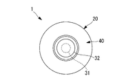
- FIG. FIG. 5 is a bottom view of the plug 1.
- the plug 1 is a member made of metal.
- metals forming the plug 1 include chromium-containing alloy steels such as 12Cr steel, 9Cr steel, and 2Cr steel.
- the material of the metal forming the plug 1 is the same as or similar to the material of the metal forming the pipe 50, which will be described later.
- the plug 1 includes a nozzle portion 20, a sealing portion 30 and a groove portion 40.
- the nozzle portion 20 is a columnar portion extending along the direction of the axis X. As shown in FIG. The nozzle portion 20 has a bottom surface 22 . The bottom surface 22 faces the pipe 50 (more specifically, the through hole 51) when the plug 1 is installed in the pipe 50 (see FIG. 6). A sealing portion 30 and a groove portion 40 are connected to the bottom surface 22 .
- the diameter of the nozzle portion 20 is larger than the inner diameter of a through hole 51 formed in the pipe 50 (see FIG. 6), for example, about ⁇ 100 mm to ⁇ 130 mm. Note that the diameter of the nozzle portion 20 is also the maximum outer diameter of the plug 1 .
- the sealing portion 30 is a portion formed to extend from the bottom surface 22 of the nozzle portion 20 .
- the sealing portion 30 is inserted into a through-hole 51 formed in the pipe 50 described later (see FIG. 6) when the plug 1 is installed in the pipe 50 described later.
- the sealing portion 30 has a shaft portion 31 and a disc portion 32 .
- the shaft portion 31 is a columnar portion extending along the direction of the axis X, and has a base end connected to the bottom surface 22 of the nozzle portion 20 and integrated with the nozzle portion 20 . In consideration of ease of manufacture, it is preferable that the shaft portion 31 has a columnar shape.
- the diameter of the shaft portion 31 is smaller than the inner diameter of a through hole 51 formed in a pipe 50 (see FIG. 6). For example, if the inner diameter of the through hole 51 is approximately ⁇ 50 mm, the diameter of the shaft portion 31 is approximately ⁇ 20 mm.
- the disc portion 32 is a plate-like portion, connected to the tip of the shaft portion 31 and integrated with the shaft portion 31 .
- the disk portion 32 defines a space (retention space S) with the nozzle portion 20 when the sealing portion 30 is inserted into the through hole 51 (see FIG. 6).
- the disk portion 32 has a shape corresponding to the cross-sectional shape of the through hole 51 perpendicular to the axis X (see FIG. 6). Note that the corresponding shape does not mean a completely identical shape, but means a shape with a gap that allows smooth insertion of the disk portion 32 into the through hole 51 . For example, if the inner diameter of the through-hole 51 is approximately ⁇ 50 mm, the diameter of the disc portion 32 is approximately ⁇ 49.8 mm.
- a gap of 0.1 mm is provided on both sides in the radial direction between the disk portion 32 and the through hole 51 .
- this gap is not limited to 0.1 mm, if it is excessively large, gas for a back shield, which will be described later, is likely to leak, and steam flowing inside the pipe 50 and foreign matter contained in the steam are likely to enter. . Therefore, it is necessary to set the dimensions of the disk portion 32 so that the gap is not excessively large.
- the gaps on both sides in the radial direction be 0.4 mm or less, and the closer to 0.1 mm, the more preferable.
- the groove portion 40 is a portion formed so as to protrude from the bottom surface 22 of the nozzle portion 20 on the tip 11 side of the plug 1 .
- the groove portion 40 has a groove surface 41 and a straight surface 42 .
- the groove surface 41 is an inclined surface whose diameter is reduced from the outer peripheral surface of the nozzle portion 20 toward the axis X in the direction from the proximal end 12 to the distal end 11 of the plug 1 .
- the groove surface 41 is formed in an annular shape in the circumferential direction about the axis X. As shown in FIG.
- the straight surface 42 is a surface connected to the tip (the end near the axis X) of the groove surface 41 near the bottom surface 22 of the plug 1, and extends along the axis from the tip 11 of the plug 1 toward the base end 12. It extends along the X direction.
- the straight surface 42 is parallel or substantially parallel to the axis X. As shown in FIG.
- the straight surface 42 is formed in an annular shape in the circumferential direction about the axis X, like the groove surface 41 .
- the straight surface 42 preferably has a length dimension in the direction of the axis X of 10 mm or more and 14 mm or less. If the length dimension is 9 mm or less, poor welding may occur. Moreover, if the length dimension is 15 mm or more, it may be difficult to process the straight surface 42 .
- the base end of the straight surface 42 is connected to the bottom surface 22 via a quarter arc-shaped round surface 44 .
- the round surface 44 has, for example, an outer diameter of the plug 1 (that is, a diameter of the nozzle portion 20) of 110 mm and a thickness dimension (thickness in the radial direction from the straight surface 42 to the outermost peripheral surface of the nozzle portion 20) of 30 mm. If so, it is preferable that the radius is 4 mm or less.
- the numerical value of 4 mm is the minimum value within the range of dimensions that can ensure the length of the straight surface 42 for eliminating defects during welding and also satisfies the service life (for example, 240,000 hours).
- the radius of the round surface 44 is determined within the above dimensions so that the straight surface 42 is located radially outside the inner diameter of a through hole 51 formed in the pipe 50, which will be described later.
- the groove portion 40 projecting sharply in a V shape is formed in the lower portion of the plug 1 .
- the groove portion 40 is formed in an annular shape in the circumferential direction about the axis X, like the groove surface 41 and the straight surface 42 .
- the groove portion 40 is formed so as to protrude toward the pipe 50 when the plug 1 is installed in the pipe 50 described later. As a result, it is possible to improve the melt penetration of the molten metal during welding with the pipe 50, and to suppress the occurrence of unwelded portions in the portions to be welded.
- a root surface 43 may be formed between the groove surface 41 and the straight surface 42 at the tip of the groove portion 40 .
- FIG. 6 is a cross-sectional view of the pipe 50 in which the plug 1 is installed in the longitudinal direction (the right side of the axis X in the drawing) and the circumferential direction (the left side of the axis X in the drawing).
- FIG. 7 is a cross-sectional view along section line VII-VII shown in FIG.
- FIG. 8 is a longitudinal and circumferential sectional view of a pipe 50 to which the plug 1 is fixed by welding.
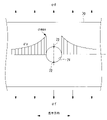
- FIG. 9 is a reference diagram showing the concept of the stress concentrated portion.
- the piping 50 shown in FIGS. 6 and 8 is a cross-sectional view, it is drawn without hatching.
- the pipe 50 is a pipe that constitutes the steam system (L3, L5 in FIG. 1), and high-temperature and high-pressure steam flows inside.
- the thickness of the pipe 50 is, for example, approximately 25 mm to 130 mm.
- a through-hole 51 for inserting a radiation source for radiographic examination is formed in the pipe 50 .
- the through-hole 51 is a straight tubular hole that penetrates the pipe wall of the pipe 50 in its thickness direction, and communicates the outside and the inside of the pipe 50 .
- the through holes 51 are preferably formed in the vicinity of joints between the pipes 50 .
- the through hole 51 may be formed with a gap between the joints between the pipes 50 as long as the radiation source inserted into the through hole 51 can be appropriately inspected.
- the plug 1 is installed in the pipe 50 such that at least a portion of the sealing portion 30 is inserted into the through hole 51 and the groove portion 40 abuts against the outer peripheral surface of the pipe 50 . be. At this time, the axis X of the plug 1 substantially coincides with the axis of the through hole 51 .
- the through hole 51 into which the sealing portion 30 is inserted includes the bottom surface 22 of the nozzle portion 20, the shaft portion 31, the disc portion 32, the straight surface 42 and the round surface 44 of the groove portion 40, and the through hole 51.
- a retention space S is defined by the inner peripheral surface of the . As shown in FIG. 7, the retention space S has an annular shape around the axis X. As shown in FIG.
- the retention space S is a space for retaining back shield gas when connecting the plug 1 to the pipe 50 by welding.
- Back shielding is to replace the oxygen-containing gas such as air in the space in contact with the back surface of the first layer bead with an inert gas during the first layer welding.
- the oxygen-containing gas such as air in the space in contact with the back surface of the first layer bead
- an inert gas during the first layer welding.
- the space in contact with the back surface of the first-layer bead is an open space, the inert gas diffuses into the space, and the oxidation suppressing effect is lost. Therefore, as described above, it is generally necessary to use a sealing member such as a balloon to define a space in which the inert gas is retained.
- the back shield gas include inert gases such as nitrogen and argon.
- the disk portion 32 inserted into the through hole 51 is set so that the lower surface 32 a is substantially flush with the inner peripheral surface of the pipe 50 .
- the step between the lower surface 32a and the inner peripheral surface of the pipe 50 is reduced, making it difficult for foreign matter contained in the steam to adhere.
- by not obstructing the flow of steam turbulence of the steam flow in the vicinity of the disk portion 32 is suppressed. And the amount of foreign matter contained in steam can be reduced.
- the disc portion 32 is brought closer to the inner peripheral surface side of the pipe 50, the volume of the retention space S can be secured as large as possible.
- the lower surface 32a is the surface of the disk portion 32 facing the inside of the pipe 50 (steam flow path).
- a groove for welding is formed between the groove portion 40 and the outer peripheral surface of the pipe 50 by abutting the groove portion 40 against the outer peripheral surface of the pipe 50 .
- a predetermined gap (root gap) is secured and held.
- the root spacing is, for example, 2 mm to 7 mm.
- the outer peripheral surface of the pipe 50 is radially inside the tip of the groove portion 40. (part A surrounded by a dotted square in FIG. 6).
- the outer peripheral surface of the pipe 50 from the tip of the groove portion 40 to the through hole 51 functions as a receiving portion for molten metal flowing out from the gap between the tip of the groove portion 40 and the outer peripheral surface of the pipe 50 when welding is started.
- the melt penetration at the start of welding can be improved. As a result, it is possible to suppress the occurrence of an unwelded portion in the portion to be welded, thereby suppressing the occurrence of a discontinuous weld penetration shape.
- the groove surface 41 of the groove portion 40 or the outer peripheral surface of the nozzle portion 20 and the outer peripheral surface of the pipe 50 are placed so as to cover the initial layer welding region between the groove portion 40 and the outer peripheral surface of the pipe 50.
- a heat-resistant seal is affixed between and and the gas for the back shield is supplied to the retention space S through the cut of the seal.
- the air originally present in the retention space S is discharged from the gap between the disk portion 32 and the inner peripheral surface of the through hole 51 as the gas for the back shield is supplied.
- welding is started.
- first layer welding is performed over the entire circumference of the groove portion 40 while peeling off the seal, and then, as shown in FIG.
- the plug 1 and the pipe 50 are connected by forming a welded portion 60 by depositing molten metal. Thereby, the through hole 51 can be closed with the plug 1 .
- the position of the weld toe 61 is positioned farther from the axis X than the outer peripheral surface of the nozzle portion 20, that is, positioned radially outside the outer peripheral surface of the nozzle portion 20. It is preferable to keep With this configuration, the weld toe 61 can be kept away from the stress concentration portion 53 generated inside the pipe 50 (inside the pipe wall).
- the weld toe 61 is the end of the portion of the welded portion 60 in contact with the pipe 50, and is the end located radially outward.
- the stress concentration portion 53 will be described below with reference to FIG. It is assumed that a tensile stress ⁇ f is applied to the long side of a flat plate 70 formed with a through hole 71 and extending in the longitudinal direction. At this time, as is known, the stress ⁇ y acting on the center line of the flat plate 70 produces a maximum stress ⁇ max near the through-hole 71 in the longitudinal direction (so-called stress concentration). Note that the maximum stress ⁇ max is about three times the stress generated at the through-hole point 72 .
- a hoop stress acts on the pipe 50 in the circumferential direction of the through hole 51 due to the pressure of the steam flowing inside.
- a stress concentrated portion 53 is generated in the vicinity.
- part of the stress of the stress concentration portion 53 generated by the hoop stress can be borne by the nozzle portion 20, and the weld toe 61 is the stress concentration portion generated inside the pipe 50. Since it is located radially outside of 53 with respect to the direction of the axis X, stress concentration due to hoop stress can be alleviated, and the service life of weld toe 61 and pipe 50 can be extended.
- the position of the weld toe 61 of the weld 60 is preferably determined as follows.
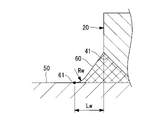
- the weld leg length of the welded portion 60 projecting radially from the outer peripheral surface of the nozzle portion 20 of the plug 1 is Lw. That is, the distance along the radial direction (the radial direction of the plug 1) from the outer peripheral surface of the plug 1 to the weld toe 61 is defined as Lw.
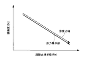
- the relationship between the weld leg length Lw and the damage degree Dc at the stress concentrated portion 53 and the relationship between the weld leg length Lw and the damage degree Dc at the weld toe 61 are as shown in the graph of FIG. That is, the degree of damage Dc at the stress concentration portion 53 decreases as the weld leg length Lw increases. Further, as the weld leg length Lw increases, the degree of damage Dc at the weld toe 61, particularly at the weld toe 61 (see FIG. 8) in the circumferential direction of the pipe 50 increases.
- the degree of damage Dc indicates the influence of the damage on the metal structure, and indicates the degree of influence on the deterioration factor of material performance such as mechanical strength.
- the welded portion 60 near the weld toe 61 is preferably formed into a rounded shape that is smoothly curved. Thereby, stress concentration at the weld toe 61 can be suppressed.
- the radius of the weld toe 61 formed in a round shape is defined as Rw.
- the relationship between the radius Rw and the degree of damage Dc at the stress concentration portion 53 and the relationship between the radius Rw and the degree of damage Dc at the weld toe 61 are as shown in the graph of FIG. That is, the degree of damage Dc at the stress concentrated portion 53 and the degree of damage Dc at the weld toe 61 decrease as the radius Rw increases. Therefore, it is preferable to set the radius Rw large.
- the through hole 51 is formed near the joint between the pipes 50
- the larger the radius Rw is set, the more the weld toe 61 becomes the joint between the pipes 50. will approach. In this case, the thermal influence of forming the welded portion 60 may reach the joints between the pipes 50, which is not preferable.
- the position of the weld toe 61 is fixed, the larger the radius Rw is set, the farther the position of the through-hole 51 is from the weld joint between the pipes 50 .
- the through-hole 51 is separated from the welded joint between the pipes 50, and there is a possibility that the operation of inserting the radiation source through the through-hole 51 for the radiographic examination may be hindered, which is not preferable.
- the radius Rw of the welded portion 60 is a range that does not exert a thermal effect on the joints of the pipes 50 during welding, and the work of inserting the radiation source for the radiographic test from the through hole 51 is hindered. It is preferable to set the value as large as possible within a range in which no For example, it is desirable to set the radius Rw of the welded portion 60 within a range of 10 mm to 30 mm.
- the gas for the back shield by a simple operation of using the plug 1, and to reduce ancillary work associated with welding the plug 1 and the pipe 50 together.
- the sealing portion 30 includes a shaft portion 31 connected to the nozzle portion 20 at its proximal end and having a smaller diameter than the inner diameter of the through hole 51, and a through hole connected to the distal end of the shaft portion 31 and perpendicular to the axis X. 51 and the disk portion 32 having a shape corresponding to the cross-sectional shape of the disk 51 . Intrusion of foreign matter into the through hole 51 can be suppressed by the portion 32 . In addition, since the disk portion 32 functions as a guide for the through hole 51, positioning when inserting the sealing portion 30 into the through hole 51 can be easily performed.
- the lower surface 32a of the disc portion 32 is configured to be substantially flush with the inner peripheral surface of the pipe 50, there is no step between the surface of the disc portion 32 and the inner peripheral surface of the pipe 50. It becomes difficult for foreign matter to adhere. In addition, it is possible to prevent the disk portion 32 from obstructing the flow of steam flowing inside the pipe 50 . Furthermore, since the flow of steam is not hindered, the turbulence of the steam flow in the vicinity of the disk portion 32 is suppressed. Quantity and the amount of contaminants contained in the steam can be reduced. Moreover, since the disc portion 32 is brought as close to the inner peripheral surface side of the pipe 50 as possible, the volume of the retention space S in which a sufficient amount of gas can be retained can be secured.
- the plug 1 can be connected to the pipe 50 by welding using the groove portion 40 .
- the groove portion 40 has a groove surface 41 and a straight surface 42
- the formed groove portion 40 is butted against the outer peripheral surface of the pipe 50 and welded, so that when welding is started, It is possible to improve melt penetration.
- the outer peripheral surface of the pipe 50 exists by the distance from the tip of the groove portion 40 formed by the straight surface 42 and the groove surface 41 to the through hole 51. It will be.
- the outer peripheral surface of the pipe 50 from the tip of the protruding groove portion 40 to the through hole 51 is a receiving portion for molten metal flowing out from between the tip of the groove portion 40 and the outer peripheral surface of the pipe 50 at the start of welding.
- the melting of molten metal can be further improved, and the occurrence of unwelded portions can be suppressed.
- the penetration of the molten metal in this way, the occurrence of a discontinuous weld penetration shape in which there is an unwelded part in the part to be welded is suppressed.
- the straight surface 42 is located radially outside the through hole 51 when the groove portion 40 abuts against the pipe 50 , the groove formed by the straight surface 42 and the groove surface 41
- the outer peripheral surface of the pipe 50 exists by the distance from the tip of the portion 40 to the through hole 51 .
- the outer peripheral surface of the pipe 50 from the tip of the groove portion 40 to the through hole 51 functions as a receiving portion for the molten metal flowing out from between the tip of the groove portion 40 and the outer peripheral surface of the pipe 50 at the start of welding.
- the penetration of molten metal can be further improved, and the occurrence of a discontinuous weld penetration shape such as an unwelded portion in the portion to be welded can be suppressed.
- the plug 1 since the plug 1 has the sealing portion 30 inserted into the through hole 51, the back shield gas can be retained in the retention space S when the plug 1 is welded to the pipe 50. As a result, it is possible to seal the gas for a good back shield by a simple operation of using the plug 1, and to reduce the burden of incidental work involved in welding the plug 1 and the pipe 50 together.
- the plug 1 is connected to the pipe 50 by forming a welded portion 60 between the groove surface 41 of the groove portion 40 and the outer peripheral surface of the pipe 50, with the groove portion 40 abutting against the outer peripheral surface of the pipe 50. Therefore, the entire welded portion 60 can be formed on the outer peripheral surface of the pipe 50 . As a result, the presence or absence of defects in the welded portion 60 can be inspected by a non-destructive method, so that the inspection of the welded portion 60 can be easily performed. In addition, since all the welded portions 60 to be inspected are formed on the outer peripheral surface of the pipe 50, the accuracy of inspection is improved.
- the welded portion 60 is more stress concentrated than the stress concentrated portion generated inside the pipe material of the pipe 50 and near the through hole 51.
- a weld toe 61 can be positioned radially outward.
- the nozzle portion 20 can bear part of the stress generated in the stress concentration portion. Therefore, the proof stress of the pipe 50 can be improved.
- stress concentration generated in the welded portion 60 can be alleviated, and the strength of the welded portion 60 can be secured and the service life of the welded portion 60 can be extended.
- the “stress concentration portion” referred to here means a peak portion of stress generated in the vicinity of the through-hole 51 by the hoop stress acting on the pipe 50 and its vicinity.
- the position of the weld toe 61 is determined by comparing the degree of damage of the stress concentration portion and the degree of damage of the weld toe 61, both the stress concentration portion and the weld toe 61 are damaged.
- the weld toe 61 can be set at a difficult position.
- the welded portion 60 is formed in a round shape that curves concavely with respect to the outer peripheral surface of the pipe 50, concentration of stress on the weld toe 61 can be suppressed. As a result, even if the nozzle portion 20 bears part of the stress generated in the stress concentration portion of the pipe 50 , it is possible to suppress damage to the welded portion 60 due to the stress.
- a plug (1) according to one aspect of the present disclosure is a plug (1) that closes a through hole (51) formed in a pipe (50) from the outer peripheral surface side of the pipe (50), A columnar nozzle portion (20) extending in the (X) direction is connected to the nozzle portion (20) and retains gas between the nozzle portion (20) and the through hole (51). a sealing portion (30) defining a retention space (S) for allowing
- the columnar nozzle portion (20) extending in the direction of the axis (X) is connected to the nozzle portion (20), and the nozzle portion is inserted into the through hole (51). (20) and a sealing portion (30) defining a retention space (S) for retaining gas.
- the back shield gas can be retained in the retention space (S).
- the gas for the back shield can be effectively sealed by a simple operation of using the plug (1), and the burden of incidental work associated with welding the plug 1 and the pipe 50 can be reduced.
- the sealing portion (30) has a smaller diameter than the inner diameter of the through hole (51), and a proximal end thereof is connected to the nozzle portion (20). and a disk portion (32) connected to the tip of the shaft portion (31) corresponding to the inner shape of the through hole (51).
- the sealing part (30) has a diameter smaller than the inner diameter of the through hole (51), and the base end of the shaft part (31) is connected to the nozzle part (20). and a disc portion (32) connected to the tip of the shaft portion (31) corresponding to the inner shape of the through hole (51). 31), the disk portion (32) and the through hole (51) define the retention space (S), and the disk portion (32) can prevent foreign matter from entering the through hole (51).
- the disk portion (32) functions as a guide for the through hole (51), it is possible to easily position the sealing portion (30) when inserting it into the through hole (51).
- the surface (32a) of the disk portion (32) facing the inner side of the pipe (50) is substantially flush with the inner peripheral surface of the pipe (50). is configured to be
- the surface (32a) of the disk portion (32) facing the inside of the pipe (50) is configured to be substantially flush with the inner peripheral surface of the pipe (50).
- the disk portion (32) it is possible to prevent the disk portion (32) from obstructing the flow of steam flowing inside the pipe (50).
- the retention space ( S) it is possible to reduce the amount of steam entering the interior and the amount of foreign matter contained in the steam.
- the disk portion (32) since the disk portion (32) is brought as close to the inner peripheral surface of the pipe (50) as possible, the volume of the retention space (S) in which a sufficient amount of gas can be retained can be secured.
- the plug (1) according to one aspect of the present disclosure includes a groove (40) that is formed to protrude from the nozzle (20) and that abuts against the outer peripheral surface of the pipe (50). ing.
- the groove (40) is formed so as to protrude from the nozzle (20) and is abutted against the outer peripheral surface of the pipe (50).
- the plug (1) can be connected to the pipe (50) by welding using the part (40).
- the groove portion (40) has a radial outer circumference perpendicular to the axis (X) direction in the direction from the proximal end (12) to the distal end (11).
- a groove surface (41) contracting from the side, and from the end of the groove surface (41), from the tip (11) side toward the base end (12) along the axis (X) direction. and a straight surface (42) extending along the rim.
- the groove portion (40) is contracted from the outer peripheral side in the radial direction orthogonal to the axis (X) direction in the direction from the proximal end (12) to the distal end (11). and a straight surface (42) extending along the axis (X) from the end of the groove surface (41) toward the base end (12) from the tip (11) side. , so that the formed groove portion (40) is butt-welded against the outer peripheral surface of the pipe (50), thereby making it possible to improve the penetration of molten metal at the start of welding.
- the groove (40) when the groove (40) is butted against the pipe (50), the distance from the groove (40) formed by the straight surface (42) and the groove surface (41) to the through hole (51) The outer peripheral surface of the pipe (50) is present for the amount of .
- the outer peripheral surface of the pipe (50) from the tip of the protruding groove (40) to the through hole (51) is the same as the tip of the groove (40) and the outer peripheral surface of the pipe (50) at the start of welding. Since it functions as a receiving portion for the molten metal flowing out from between, it is possible to further improve the melting of the molten metal and suppress the occurrence of unwelded portions.
- the straight surface (42) is configured such that, when the groove portion (40) abuts against the outer peripheral surface of the pipe (50), the straight surface (42) extends in the radial direction. It is positioned outside the through hole (51).
- the straight surface (42) is located radially outside the through hole (51) when the groove (40) is butted against the pipe (50). Therefore, the outer peripheral surface of the pipe (50) exists by the distance from the tip of the groove (40) formed by the straight surface (42) and the groove surface (41) to the through hole (51). It will be. The outer peripheral surface of the pipe (50) from the tip of the groove (40) to the through hole (51) flows out from between the tip of the groove (40) and the outer peripheral surface of the pipe (50) at the start of welding.
- a piping structure includes a piping (50) having a through hole (51) formed therein, and the plug (1), wherein the plug (1) is the sealing portion (30) is inserted into the through hole (51).
- the plug (1) since the plug (1) has the sealing part (30) inserted into the through hole (51), the plug (1) is welded to the piping (50). Occasionally, the back shield gas can be retained in the retention space (S). As a result, the gas for the back shield can be effectively sealed by a simple operation of using the plug (1), and the burden of incidental work associated with welding the plug 1 and the pipe 50 can be reduced.
- a piping structure includes a piping (50) having a through hole (51) formed therein, and the above-described plug (1), wherein the plug (1) includes the groove portion (40) is abutted against the outer peripheral surface of the pipe (50), and a welded portion (60) is formed between the groove portion (40) and the outer peripheral surface of the pipe (50) to form the pipe ( 50).
- the plug (1) has the groove portion (40) butted against the outer peripheral surface of the pipe (50), and the groove portion (40) and the outer peripheral surface of the pipe (50) are aligned. Since the weld (60) is formed between and connected to the pipe (50), the entire weld (60) can be formed on the outer peripheral surface of the pipe (50). As a result, the presence or absence of defects in the weld (60) can be inspected by a non-destructive method, so the inspection of the weld (60) can be easily carried out. In addition, since all the welded portions (60) to be inspected are formed on the outer peripheral surface of the pipe (50), the accuracy of inspection is improved.
- the welded portion (60) is such that the end portion (61) of the portion in contact with the pipe (50) is closer to the axis ( X).
- the end (61) of the welded part (60) in contact with the pipe (50) is further away from the axis (X) than the outer peripheral surface of the nozzle part (20). Therefore, the end (61) of the welded portion (60) can be positioned radially outside the stress concentration portion generated inside the pipe material of the pipe (50) and near the through hole (51). .
- part of the stress generated in the stress concentrated portion can be borne by the nozzle portion (20). Therefore, the proof stress of the pipe (50) can be improved.
- the stress concentration generated in the welded portion (60) can be alleviated, and the strength of the welded portion (60) can be secured and the service life of the welded portion (60) can be extended.
- the "stress concentration portion" referred to here means a peak portion of stress generated in the vicinity of the through hole (51) due to the hoop stress acting on the pipe (50) and its vicinity.
- the position of the end (61) of the weld (60) depends on the degree of damage of the stress concentration portion and the end (61) of the weld (60). ) is determined by comparing the degree of damage of
- the position of the end (61) of the weld (60) depends on the degree of damage of the stress concentrated portion, the degree of damage of the end (61) of the weld (60), , the end (61) of the welded portion (60) can be set at a position where both the stress concentration portion and the end (61) of the welded portion (60) are unlikely to be damaged.
- the welded portion (60) is formed in a round shape concavely curved with respect to the outer peripheral surface of the pipe (50).
- the welded portion (60) is formed in a round shape that curves concavely with respect to the outer peripheral surface of the pipe (50). 61) can be suppressed from stress concentration. As a result, even if the nozzle part (20) bears part of the stress generated in the stress concentration part of the pipe (50), the weld part (60) can be prevented from being damaged by the stress.
- a method for installing a plug (1) is a plug (1) that closes a through hole (51) formed in a pipe (50) from the outer peripheral surface side of the pipe (50), , a columnar nozzle portion (20) extending in the direction of the axis (X), and a nozzle portion (20) connected to the nozzle portion (20) to provide a gas flow between the nozzle portion (20) and the through hole (51). and a sealing part (30) defining a retention space (S) for retaining a gas used for a back shield during welding, the gas being used for the retention space (S). including the step of supplying to
Landscapes
- Engineering & Computer Science (AREA)
- Physics & Mathematics (AREA)
- Plasma & Fusion (AREA)
- Mechanical Engineering (AREA)
- General Engineering & Computer Science (AREA)
- High Energy & Nuclear Physics (AREA)
- Butt Welding And Welding Of Specific Article (AREA)
Abstract
プラグ自体でバックシールド用のガスを封止できるプラグ、配管構造物及びプラグの設置方法を提供する。配管(50)に形成された貫通孔(51)を配管(50)の外周面側から閉塞するプラグ(1)であって、軸線(X)方向に延びた柱状の管台部(20)と、管台部(20)に接続され、貫通孔(51)内において管台部(20)との間にガスを滞留させる滞留空間(S)を画定する封止部(30)と、を備えている。また、封止部(30)は、貫通孔(51)の内径よりも小径であり、基端が管台部(20)に接続された軸部(31)と、貫通孔(51)の内形状に対応して、軸部(31)の先端に接続された円板部(32)と、を有している。
Description
本開示は、プラグ、配管構造物及びプラグの設置方法に関する。
発電プラントなどに用いられる大型のボイラは、中空形状をなして鉛直方向に設置される火炉を有し、この火炉壁に複数の燃焼バーナが火炉の周方向に沿って配設されている。また、ボイラは、火炉の鉛直方向上方に煙道が連結されており、この煙道に蒸気を生成するための熱交換器が配置されている。そして、燃焼バーナが火炉内に燃料と空気(酸化性ガス)との混合気を噴射することで火炎が形成され、燃焼ガスが生成されて煙道に流れる。燃焼ガスが流れる領域に熱交換器が設置され、熱交換器を構成する伝熱管内を流れる水や蒸気を加熱して過熱蒸気が生成される。
ボイラを有する発電プラントに使用される蒸気系統は、複数の配管同士が溶接で接続されて構成される。この場合、接合部の健全性(欠陥の有無)を確認するために、放射線透過試験を実施することがある。このため、接合部の近傍には、配管の内部に放射線試験機器(放射線源)を挿入するための貫通孔が穿設される。放射線透過試験は溶接後に一度だけ実施されることが通常であり、放射線透過試験終了後には穿設された貫通孔を閉塞する必要がある。
貫通孔を閉塞する方法として、例えば特許文献1には、閉止プラグが開示されている。特許文献1の閉止プラグは、溶接によって配管に対して固定されている。
プラグを配管に溶接する場合、溶接部の内面の酸化を抑制して溶接の品質を良好なものにするために、バックシールドを行うことがある。ここで、バックシールドを行う方法としては、風船を用いて配管内部にあるバックシールド用のガス(例えば、窒素やアルゴン等の不活性ガス)の拡散を防止する方法が例示される。しかしながら、この方法では風船の取付けや撤去に手間がかかるので、可能な限り簡易な方法でバックシールド用のガスを封止することが好ましい。
本開示は、このような事情に鑑みてなされたものであって、プラグ自体でバックシールド用のガスを封止できるプラグ、配管構造物及びプラグの設置方法を提供することを目的とする。
上記課題を解決するために、本開示のプラグ、配管構造物及びプラグの設置方法は以下の手段を採用する。
すなわち、本開示の一態様に係るプラグは、配管に形成された貫通孔を前記配管の外周面側から閉塞するプラグであって、軸線方向に延びた柱状の管台部と、前記管台部に接続され、前記貫通孔内において前記管台部との間にガスを滞留させる滞留空間を画定する封止部と、を備えている。
すなわち、本開示の一態様に係るプラグは、配管に形成された貫通孔を前記配管の外周面側から閉塞するプラグであって、軸線方向に延びた柱状の管台部と、前記管台部に接続され、前記貫通孔内において前記管台部との間にガスを滞留させる滞留空間を画定する封止部と、を備えている。
また、本開示の一態様に係る配管構造物は、貫通孔が形成された配管と、蒸気のプラグと、を備え、前記プラグは、前記封止部が前記貫通孔に挿入されている。
また、本開示の一態様に係るプラグの設置方法は、配管に形成された貫通孔を前記配管の外周面側から閉塞するプラグであって、軸線方向に延びた柱状の管台部と、前記管台部に接続され、前記貫通孔内において前記管台部との間にガスを滞留させる滞留空間を画定する封止部と、を備えているプラグの設置方法であって、溶接時のバックシールドに用いられるガスを前記滞留空間に供給する工程を含む。
本開示によれば、プラグ自体でバックシールド用のガスを封止できる。
[ボイラ発電プラントについて]
まず、本開示の一実施形態に係るプラグが設置されるボイラ発電プラントについて図1を用いて説明する。
まず、本開示の一実施形態に係るプラグが設置されるボイラ発電プラントについて図1を用いて説明する。
図1は、ボイラ発電プラントにおける蒸気、復水、給水系統を表す概略図である。
ボイラ発電プラントは、ボイラの熱交換器102,103,104と、ボイラが生成した蒸気によって回転駆動される蒸気タービン110と、蒸気タービン110に連結され、蒸気タービン110の回転に応じて発電を行う発電機115とを備える。
ボイラ発電プラントは、ボイラの熱交換器102,103,104と、ボイラが生成した蒸気によって回転駆動される蒸気タービン110と、蒸気タービン110に連結され、蒸気タービン110の回転に応じて発電を行う発電機115とを備える。
蒸気タービン110は、例えば、高圧タービン111と中圧タービン112と低圧タービン113とから構成され、後述する再熱器105,106からの蒸気が中圧タービン112に流入したのちに低圧タービン113に流入する。
低圧タービン113には、復水器114が連結されており、低圧タービン113を回転駆動した蒸気がこの復水器114で冷却水(例えば海水)により冷却されて復水となる。復水器114は、給水系統L1を介して節炭器107に連結されている。
給水系統L1には、例えば、復水ポンプ(CP)121、低圧給水ヒータ122、ボイラ給水ポンプ(BFP)123、高圧給水ヒータ124が設けられている。
低圧給水ヒータ122と高圧給水ヒータ124には、蒸気タービン110を駆動する蒸気の一部が抽気されて、図示しない抽気系統を介して高圧給水ヒータ124と低圧給水ヒータ122に熱源として供給され、節炭器107へ供給される給水が加熱される。
以下、ボイラが貫流ボイラの場合を例にして説明をする。
節炭器107は、火炉壁101の各蒸発管に連結されている。節炭器107で加熱された給水は、火炉壁101の蒸発管を通過する際に、火炉内の火炎から輻射を受けて加熱され、汽水分離器126へと導かれる。汽水分離器126にて分離された蒸気は、過熱器102,103,104へと供給され、汽水分離器126にて分離されたドレン水は、ドレン水系統L2を介して復水器114へと導かれる。
節炭器107は、火炉壁101の各蒸発管に連結されている。節炭器107で加熱された給水は、火炉壁101の蒸発管を通過する際に、火炉内の火炎から輻射を受けて加熱され、汽水分離器126へと導かれる。汽水分離器126にて分離された蒸気は、過熱器102,103,104へと供給され、汽水分離器126にて分離されたドレン水は、ドレン水系統L2を介して復水器114へと導かれる。
燃焼ガスが燃焼ガス通路(煙道)13を流れるとき、この燃焼ガスは、過熱器102,103,104、再熱器105,106、節炭器107で熱回収される。一方、ボイラ給水ポンプ(BFP)123から供給された給水は、節炭器107によって予熱された後、火炉壁101の各蒸発管を通過する際に加熱されて蒸気となり、汽水分離器126に導かれる。
汽水分離器126で分離された蒸気は、過熱器102,103,104に導入され、燃焼ガスによって過熱される。
過熱器102,103,104で生成された過熱蒸気は、蒸気系統L3を介して高圧タービン111に供給され、この高圧タービン111を回転駆動する。
高圧タービン111から排出された蒸気は、蒸気系統L4を介して再熱器105,106に導入されて再度過熱される。再度過熱された蒸気は、蒸気系統L5を介して中圧タービン112を経て低圧タービン113に供給され、中圧タービン112及び低圧タービン113を回転駆動する。
各蒸気タービン111,112,113の回転軸は、発電機115に接続されている。各蒸気タービン111,112,113の回転軸が回転することで、発電機115を回転駆動されて発電が行われる。低圧タービン113から排出された蒸気は、復水器114で冷却されることで復水となり、給水系統L1を介して再び節炭器107に送られる。
上記のようなボイラ発電プラントの各蒸気系統を構成する配管50には、放射線源を挿入するために穿設された貫通孔51を閉塞するプラグ1が複数個所に設置される。例えば、同図において各蒸気系統上の箇所Pに設置される。なお、同図の箇所Pは例示であり、全ての設置箇所を示したものではない。
[プラグについて]
次に、本開示の一実施形態に係るプラグ1について図2から図5を用いて説明する。
図2は、プラグ1の側面図である。図3は、プラグ1の縦断面図である。図4は、プラグ1の平面図である。図5は、プラグ1の底面図である。
次に、本開示の一実施形態に係るプラグ1について図2から図5を用いて説明する。
図2は、プラグ1の側面図である。図3は、プラグ1の縦断面図である。図4は、プラグ1の平面図である。図5は、プラグ1の底面図である。
プラグ1は、金属製の部材とされている。
プラグ1を形成する金属としては、12Cr鋼、9Cr鋼、2Cr鋼等のクロム含有合金鋼が例示される。
ここで、溶接の容易性を考慮して、プラグ1を形成する金属の材質は、後述する配管50を形成する金属の材質と同一又は類似であることが好ましい。
プラグ1を形成する金属としては、12Cr鋼、9Cr鋼、2Cr鋼等のクロム含有合金鋼が例示される。
ここで、溶接の容易性を考慮して、プラグ1を形成する金属の材質は、後述する配管50を形成する金属の材質と同一又は類似であることが好ましい。
図2から図5に示すように、プラグ1は、管台部20、封止部30及び開先部40を備えている。
管台部20は、軸線Xの方向に沿って延びる円柱状の部分である。
管台部20は、底面22を有している。底面22は、プラグ1を後述する配管50に設置したときに、配管50(詳細には貫通孔51)に臨む面である(図6参照)。この底面22には、封止部30及び開先部40が接続されている。
管台部20の直径は、後述する配管50に形成された貫通孔51の内径よりも大径とされ(図6参照)、例えばφ100mm~φ130mm程度とされる。なお、管台部20の直径は、プラグ1の最大外径でもある。
管台部20は、底面22を有している。底面22は、プラグ1を後述する配管50に設置したときに、配管50(詳細には貫通孔51)に臨む面である(図6参照)。この底面22には、封止部30及び開先部40が接続されている。
管台部20の直径は、後述する配管50に形成された貫通孔51の内径よりも大径とされ(図6参照)、例えばφ100mm~φ130mm程度とされる。なお、管台部20の直径は、プラグ1の最大外径でもある。
封止部30は、管台部20の底面22から延びるように形成された部分である。
封止部30は、プラグ1を後述する配管50に設置するときに、後述する配管50に形成された貫通孔51に挿入される(図6参照)。
封止部30は、軸部31及び円板部32を有している。
封止部30は、プラグ1を後述する配管50に設置するときに、後述する配管50に形成された貫通孔51に挿入される(図6参照)。
封止部30は、軸部31及び円板部32を有している。
軸部31は、軸線Xの方向に沿って延びる柱状の部分であり、基端が管台部20の底面22と接続され管台部20と一体化している。なお、製作の容易性を考慮して、軸部31は円柱状であることが好ましい。
軸部31の直径は、後述する配管50に形成された貫通孔51の内径よりも小径とされる(図6参照)。例えば、貫通孔51の内径がφ50mm程度であれば、軸部31の直径はφ20mm程度とされる。
軸部31の直径は、後述する配管50に形成された貫通孔51の内径よりも小径とされる(図6参照)。例えば、貫通孔51の内径がφ50mm程度であれば、軸部31の直径はφ20mm程度とされる。
円板部32は、板状の部分であり、軸部31の先端と接続され軸部31と一体化している。
円板部32は、封止部30が貫通孔51に挿入されたときに、管台部20との間に空間(滞留空間S)を画定する(図6参照)。
円板部32の形状は、軸線Xに対して直交する貫通孔51の断面形状に対応した形状とされている(図6参照)。なお、対応した形状とは、完全に同一の形状という意味ではなく、円板部32を貫通孔51に滑らかに挿入できる程度の隙間が設けられた形状という意味である。例えば、貫通孔51の内径がφ50mm程度であれば、円板部32の直径はφ49.8mm程度とされる。つまり、円板部32と貫通孔51との間には、半径方向の両側に0.1mmずつ隙間が設けられることになる。
なお、この隙間は0.1mmに限定されないが、過度に大きい場合は後述するバックシールド用のガスが漏出しやすくなるとともに、配管50の内側を流れる蒸気及び蒸気に含まれる異物が浸入しやすくなる。このため、円板部32の寸法は、隙間が過度に大きくならないように設定する必要がある。具体的には、蒸気及び蒸気に含まれる異物の侵入を抑制するため、半径方向の両側の隙間をそれぞれ0.4mm以下とすることが好ましく、0.1mmに近い程より好ましい。
円板部32は、封止部30が貫通孔51に挿入されたときに、管台部20との間に空間(滞留空間S)を画定する(図6参照)。
円板部32の形状は、軸線Xに対して直交する貫通孔51の断面形状に対応した形状とされている(図6参照)。なお、対応した形状とは、完全に同一の形状という意味ではなく、円板部32を貫通孔51に滑らかに挿入できる程度の隙間が設けられた形状という意味である。例えば、貫通孔51の内径がφ50mm程度であれば、円板部32の直径はφ49.8mm程度とされる。つまり、円板部32と貫通孔51との間には、半径方向の両側に0.1mmずつ隙間が設けられることになる。
なお、この隙間は0.1mmに限定されないが、過度に大きい場合は後述するバックシールド用のガスが漏出しやすくなるとともに、配管50の内側を流れる蒸気及び蒸気に含まれる異物が浸入しやすくなる。このため、円板部32の寸法は、隙間が過度に大きくならないように設定する必要がある。具体的には、蒸気及び蒸気に含まれる異物の侵入を抑制するため、半径方向の両側の隙間をそれぞれ0.4mm以下とすることが好ましく、0.1mmに近い程より好ましい。
開先部40は、プラグ1の先端11側において、管台部20の底面22から突出するように形成された部分である。
開先部40は、開先面41及びストレート面42を有している。
開先部40は、開先面41及びストレート面42を有している。
開先面41は、プラグ1の基端12から先端11に向かう方向で管台部20の外周面から軸線Xに向かって縮径した傾斜面とされている。
開先面41は、軸線Xを中心とした周方向において円環状に形成されている。
開先面41は、軸線Xを中心とした周方向において円環状に形成されている。
ストレート面42は、プラグ1の底面22付近にて、開先面41の先端(軸線Xに近い端部)に接続された面であり、プラグ1の先端11から基端12に向かう方向で軸線Xの方向に沿って延びている。
ストレート面42は、軸線Xに対して平行又は略平行とされている。
ストレート面42は、開先面41と同様、軸線Xを中心とした周方向において円環状に形成されている。
ストレート面42は、軸線X方向の長さ寸法が10mm以上14mm以下とされることが好ましい。長さ寸法が9mm以下の場合、溶接不良が生じる可能性がある。また、長さ寸法が15mm以上の場合、ストレート面42の加工が困難になる可能性がある。
ストレート面42は、軸線Xに対して平行又は略平行とされている。
ストレート面42は、開先面41と同様、軸線Xを中心とした周方向において円環状に形成されている。
ストレート面42は、軸線X方向の長さ寸法が10mm以上14mm以下とされることが好ましい。長さ寸法が9mm以下の場合、溶接不良が生じる可能性がある。また、長さ寸法が15mm以上の場合、ストレート面42の加工が困難になる可能性がある。
先端が開先面41に接続されているストレート面42の基端は、四半円弧状のラウンド面44を介して底面22に接続されている。
ラウンド面44は、例えばプラグ1の外径(すなわち、管台部20の直径)が110mm、厚さ寸法(ストレート面42から管台部20の最外周面までの半径方向における肉厚)が30mmであれば、半径が4mm以下とされることが好ましい。なお、4mmという数値は、溶接時の欠陥を無くすためのストレート面42の長さを確保でき、かつ、寿命(例えば24万時間)を満足する寸法の範囲の最小値である。ラウンド面44の半径は、上記寸法の範囲内で、後述する配管50に形成された貫通孔51の内径よりもストレート面42が半径方向の外側に位置するように決定される。
ラウンド面44は、例えばプラグ1の外径(すなわち、管台部20の直径)が110mm、厚さ寸法(ストレート面42から管台部20の最外周面までの半径方向における肉厚)が30mmであれば、半径が4mm以下とされることが好ましい。なお、4mmという数値は、溶接時の欠陥を無くすためのストレート面42の長さを確保でき、かつ、寿命(例えば24万時間)を満足する寸法の範囲の最小値である。ラウンド面44の半径は、上記寸法の範囲内で、後述する配管50に形成された貫通孔51の内径よりもストレート面42が半径方向の外側に位置するように決定される。
以上のように形成された開先面41及びストレート面42によって、プラグ1の下部には、V字状に尖るように突出した開先部40が形成されている。
開先部40は、開先面41やストレート面42と同様、軸線Xを中心とした周方向において円環状に形成されている。
開先部40は、プラグ1を後述する配管50に設置したときに、配管50側に突出するように形成されている。これによって、配管50との溶接時における溶金の溶け込みを良好なものにでき、溶接されるべき部分に未溶着部が発生することを抑制できる。
なお、開先部40の先端において、開先面41とストレート面42との間にルート面43を形成してもよい。
開先部40は、開先面41やストレート面42と同様、軸線Xを中心とした周方向において円環状に形成されている。
開先部40は、プラグ1を後述する配管50に設置したときに、配管50側に突出するように形成されている。これによって、配管50との溶接時における溶金の溶け込みを良好なものにでき、溶接されるべき部分に未溶着部が発生することを抑制できる。
なお、開先部40の先端において、開先面41とストレート面42との間にルート面43を形成してもよい。
[配管構造物について]
次に、プラグ1が設置された配管50の構造について図6から図9を用いて説明する。
図6は、プラグ1が設置された配管50の長手方向(図において軸線Xの右部)及び周方向(図において軸線Xの左部)の断面図である。図7は、図6に示す切断線VII-VIIにおける断面図である。図8は、プラグ1が溶接で固定された配管50の長手方向及び周方向の断面図である。図9は、応力集中部の概念を表す参考図である。
なお、図6及び図8に示された配管50は断面図であるが、ハッチングを省略して描画している。
次に、プラグ1が設置された配管50の構造について図6から図9を用いて説明する。
図6は、プラグ1が設置された配管50の長手方向(図において軸線Xの右部)及び周方向(図において軸線Xの左部)の断面図である。図7は、図6に示す切断線VII-VIIにおける断面図である。図8は、プラグ1が溶接で固定された配管50の長手方向及び周方向の断面図である。図9は、応力集中部の概念を表す参考図である。
なお、図6及び図8に示された配管50は断面図であるが、ハッチングを省略して描画している。
配管50は、蒸気系統(図1のL3,L5)を構成する配管であり、内側に高温高圧の蒸気が流通する。
配管50の肉厚は、例えば25mm~130mm程度とされる。
配管50には、放射線透過試験用の放射線源を挿入するための貫通孔51が形成されている。貫通孔51は、配管50の管壁をその厚さ方向に貫通する直管状の孔とされており、配管50の外側と内側とを連通している。
配管50の肉厚は、例えば25mm~130mm程度とされる。
配管50には、放射線透過試験用の放射線源を挿入するための貫通孔51が形成されている。貫通孔51は、配管50の管壁をその厚さ方向に貫通する直管状の孔とされており、配管50の外側と内側とを連通している。
放射線透過試験は、配管50同士の接合部の近傍で実施される。このため、貫通孔51は、配管50同士の接合部の近傍に形成されていることが好ましい。
なお、貫通孔51に挿入する放射線源によって適切に検査可能であれば、配管50同士の接合部と間隔を空けて貫通孔51を形成してもよい。
なお、貫通孔51に挿入する放射線源によって適切に検査可能であれば、配管50同士の接合部と間隔を空けて貫通孔51を形成してもよい。
図6に示すように、プラグ1は、封止部30の少なくとも一部が貫通孔51に挿入されるとともに開先部40が配管50の外周面に突き合わされるようにして配管50に設置される。このとき、プラグ1の軸線Xは、貫通孔51の軸線に略一致している。
このとき、封止部30が挿入された貫通孔51には、管台部20の底面22、軸部31、円板部32、開先部40のストレート面42、ラウンド面44及び貫通孔51の内周面によって滞留空間Sが画定されている。図7に示すように、滞留空間Sは、軸線X周りに円環状とされている。
この滞留空間Sは、プラグ1を溶接で配管50に接続するときに、バックシールド用のガスを滞留させるための空間である。
バックシールドとは、初層溶接時において初層ビート裏面に接する空間内の空気等の酸素含有ガスを不活性ガスと置換することである。これにより、初層ビート裏面の酸化と酸化による気孔や割れなどの欠陥発生を抑制することができる。
なお、初層ビート裏面に接する空間が開放空間である場合、不活性ガスが空間内に拡散して、酸化抑制効果が失われてしまう。そのため、前述の通り、一般的には風船等の封止部材を用いて不活性ガスを滞留させる空間を画定する必要がある。
バックシールド用のガスとしては、窒素やアルゴン等の不活性ガスが例示される。
バックシールドとは、初層溶接時において初層ビート裏面に接する空間内の空気等の酸素含有ガスを不活性ガスと置換することである。これにより、初層ビート裏面の酸化と酸化による気孔や割れなどの欠陥発生を抑制することができる。
なお、初層ビート裏面に接する空間が開放空間である場合、不活性ガスが空間内に拡散して、酸化抑制効果が失われてしまう。そのため、前述の通り、一般的には風船等の封止部材を用いて不活性ガスを滞留させる空間を画定する必要がある。
バックシールド用のガスとしては、窒素やアルゴン等の不活性ガスが例示される。
ここで、貫通孔51に挿入された円板部32は、下面32aが配管50の内周面と略面一となるように設定されている。これによって、下面32aと配管50の内周面との間に段差が小さくなり蒸気に含まれる異物が付着しにくくなる。また、円板部32が配管50の内側を流れる蒸気の流れを阻害することを回避できる。更に、蒸気の流れを阻害しないことで、円板部32付近における蒸気流れの乱れが抑制されるため、貫通孔51と円板部32との隙間を介して滞留空間Sへ侵入する蒸気の量及び蒸気に含まれる異物の量を低減できる。また、円板部32を配管50の内周面側に寄せることになるので、滞留空間Sの容積を可能な限り大きく確保できる。
なお、下面32aとは、配管50の内側(蒸気の流路)に臨む円板部32の面である。
なお、下面32aとは、配管50の内側(蒸気の流路)に臨む円板部32の面である。
開先部40が配管50の外周面に突き合わされることで、開先部40と配管50の外周面との間で溶接のための開先が形成される。ここで、開先部40と配管50の外周面との間には、所定の隙間(ルート間隔)が確保されて保持される。ルート間隔は、例えば2mm~7mmである。
このとき、軸線Xの方向に対して、ストレート面42が貫通孔51の内径よりも半径方向外側に位置しているので、開先部40の先端よりも半径方向内側に配管50の外周面が存在することになる(図6において点線の四角で囲ったA部)。
開先部40の先端から貫通孔51までの配管50の外周面は、溶接開始時において開先部40の先端と配管50の外周面との隙間から流れ出る溶金の受け部分として機能する。また、開先部40を配管50の外周面に突き合わさせて溶接することで溶接開始時における溶金の溶け込みを良好なものにできる。これによって、溶接されるべき部分に未溶着部が発生することを抑制して、不連続な溶接溶け込み形状の発生を抑制できる。
開先部40の先端から貫通孔51までの配管50の外周面は、溶接開始時において開先部40の先端と配管50の外周面との隙間から流れ出る溶金の受け部分として機能する。また、開先部40を配管50の外周面に突き合わさせて溶接することで溶接開始時における溶金の溶け込みを良好なものにできる。これによって、溶接されるべき部分に未溶着部が発生することを抑制して、不連続な溶接溶け込み形状の発生を抑制できる。
溶接を開始するにあたって、開先部40と配管50の外周面との初層溶接領域を覆うように、開先部40の開先面41又は管台部20の外周面と配管50の外周面との間に耐熱性のシールを貼り、シールの切れ目からバックシールド用のガスを滞留空間Sに供給する。滞留空間Sに元々存在していた空気は、バックシールド用のガスの供給に伴って、円板部32と貫通孔51の内周面との間の隙間から排出されていく。滞留空間Sから空気が排出され滞留空間Sがバックシールド用のガスで満たされたら溶接を開始する。
具体的には、まず、シールを剥がしながら開先部40の全周にわたって初層溶接を行い、その後、図8に示すように、溶接によって開先面41と配管50の外周面との間に溶金を盛ることで溶接部60を形成してプラグ1と配管50とを接続する。これによって、貫通孔51をプラグ1で閉塞できる。
溶接部60を形成するにあたって、溶接止端61の位置は、管台部20の外周面よりも軸線Xから離れた位置、すなわち、管台部20の外周面よりも半径方向の外側に位置させておくことが好ましい。この構成によって、配管50の内部(管壁の内部)に発生している応力集中部53から溶接止端61を遠ざけることができる。
なお、溶接止端61とは、溶接部60の配管50に接する部分の端部であり、半径方向の外側に位置する端部である。
なお、溶接止端61とは、溶接部60の配管50に接する部分の端部であり、半径方向の外側に位置する端部である。
以下、応力集中部53について図9を用いて説明する。
貫通孔71が形成され長手方向に延びる平板70の長辺に、引張応力σfが負荷されているとする。このとき、既知の通り、平板70の中心線上に作用する応力σyは、貫通孔71の長手方向近傍で最大応力σmaxが発生する(いわゆる応力集中)。なお、最大応力σmaxは、貫通孔点72に発生する応力のおよそ3倍とされる。
貫通孔71が形成され長手方向に延びる平板70の長辺に、引張応力σfが負荷されているとする。このとき、既知の通り、平板70の中心線上に作用する応力σyは、貫通孔71の長手方向近傍で最大応力σmaxが発生する(いわゆる応力集中)。なお、最大応力σmaxは、貫通孔点72に発生する応力のおよそ3倍とされる。
配管50には内側を流通する蒸気の圧力によって貫通孔51の周方向にフープ応力が作用している。ここで、上述した応力集中の現象を配管50に適用した場合、図8に示すように、配管50の軸線方向(長手方向)において、配管50の内部(管壁の内部)の貫通孔51の近傍に応力集中部53が発生することになる。
本実施形態において、フープ応力により発生している応力集中部53の応力の一部は管台部20で担うことができ、溶接止端61は、配管50の内部に発生している応力集中部53よりも軸線X方向に対して半径方向の外側に位置しているので、フープ応力による応力集中を緩和して、溶接止端61や配管50の寿命延長を図ることができる。
[溶接止端の詳細について]
溶接部60の溶接止端61の位置は、詳細には、次のように決定されることが好ましい。
溶接部60の溶接止端61の位置は、詳細には、次のように決定されることが好ましい。
図10に示すように、プラグ1の管台部20の外周面から半径方向に張り出した溶接部60の溶接脚長をLwとする。すなわち、プラグ1の外周面から溶接止端61までの半径方向(プラグ1の半径方向)に沿った距離をLwとする。
このとき、溶接脚長Lwと応力集中部53における損傷度Dcとの関係、及び、溶接脚長Lwと溶接止端61における損傷度Dcとの関係は、図11に示されたグラフようになる。すなわち、溶接脚長Lwが大きくなるにつれて応力集中部53における損傷度Dcが低下する。また、溶接脚長Lwが大きくなるにつれて溶接止端61、特に、配管50の周方向の溶接止端61(図8参照)における損傷度Dcが増加する。このため、応力集中部53及び溶接止端61の両方の損傷度が、材料性能へ影響する所定の量を超え難いような溶接脚長Lwの範囲を決定することが好ましい。
ここで、損傷度Dcとは、金属組織への損傷の影響を示すものであり、機械的強度等の材料性能の低下要因への影響度を示すものとなる。
ここで、損傷度Dcとは、金属組織への損傷の影響を示すものであり、機械的強度等の材料性能の低下要因への影響度を示すものとなる。
また、図10に示すように、溶接止端61近傍の溶接部60は、滑らかな湾曲形状となるラウンド状に形成されることが好ましい。これによって、溶接止端61における応力集中を抑制できる。
ここで、ラウンド状に形成された溶接止端61の半径をRwとする。このとき、半径Rwと応力集中部53における損傷度Dcとの関係、及び、半径Rwと溶接止端61における損傷度Dcとの関係は、図12に示されたグラフのようになる。すなわち、半径Rwが大きくなるにつれて応力集中部53における損傷度Dc及び溶接止端61における損傷度Dcが低下する。このため、半径Rwは大きく設定することが好ましい。
しかしながら、貫通孔51は配管50同士の接合部近傍に形成されるという性質上、貫通孔51の位置を固定した場合、半径Rwを大きく設定するほど、溶接止端61が配管50同士の接合部に接近することになる。この場合、溶接部60を形成する際の熱的な影響が、配管50同士の接合部に及ぶ可能性があり好ましくない。
一方で、溶接止端61の位置を固定した場合、半径Rwを大きく設定するほど、貫通孔51の位置が配管50同士の溶接接合部から遠ざかることになる。この場合、配管50同士の溶接接合部から貫通孔51が離れることになり、放射線透過試験用に放射線源を貫通孔51から挿入する作業に支障が発生する可能性があり好ましくない。
以上より、溶接部60の半径Rwは、配管50同士の接合部に対して溶接時に熱的な影響を及ぼさない範囲、かつ、放射線透過試験用に放射線源を貫通孔51から挿入する作業に支障が発生しない範囲で、可能な限り大きく設定することが好ましい。例えば、溶接部60の半径Rwは、10mm~30mmの範囲で設定することが望ましい。
一方で、溶接止端61の位置を固定した場合、半径Rwを大きく設定するほど、貫通孔51の位置が配管50同士の溶接接合部から遠ざかることになる。この場合、配管50同士の溶接接合部から貫通孔51が離れることになり、放射線透過試験用に放射線源を貫通孔51から挿入する作業に支障が発生する可能性があり好ましくない。
以上より、溶接部60の半径Rwは、配管50同士の接合部に対して溶接時に熱的な影響を及ぼさない範囲、かつ、放射線透過試験用に放射線源を貫通孔51から挿入する作業に支障が発生しない範囲で、可能な限り大きく設定することが好ましい。例えば、溶接部60の半径Rwは、10mm~30mmの範囲で設定することが望ましい。
本実施形態によれは、以下の効果を奏する。
軸線Xの方向に延びた柱状の管台部20と、管台部20に接続され、貫通孔51内において管台部20との間にガスを滞留させる滞留空間Sを画定する封止部30と、を備えているので、プラグ1を配管50に溶接で接続するときに、滞留空間Sにバックシールド用のガスを滞留させることができる。これにより、プラグ1を使用するだけの簡易な作業で良好なバックシールド用のガスを封止し、プラグ1と配管50との溶接に伴う付帯作業を軽減できる。
軸線Xの方向に延びた柱状の管台部20と、管台部20に接続され、貫通孔51内において管台部20との間にガスを滞留させる滞留空間Sを画定する封止部30と、を備えているので、プラグ1を配管50に溶接で接続するときに、滞留空間Sにバックシールド用のガスを滞留させることができる。これにより、プラグ1を使用するだけの簡易な作業で良好なバックシールド用のガスを封止し、プラグ1と配管50との溶接に伴う付帯作業を軽減できる。
また、封止部30は、基端が管台部20に接続され貫通孔51の内径よりも小径である軸部31と、軸部31の先端に接続され軸線Xに対して直交する貫通孔51の断面形状に対応した形状の円板部32と、を有しているので、管台部20、軸部31、円板部32及び貫通孔51によって滞留空間Sを画定するともに、円板部32によって貫通孔51への異物の侵入を抑制することができる。
また、円板部32が貫通孔51に対するガイドとして機能するので、封止部30を貫通孔51に挿入する際の位置決めが容易にできる。
また、円板部32が貫通孔51に対するガイドとして機能するので、封止部30を貫通孔51に挿入する際の位置決めが容易にできる。
また、円板部32の下面32aは、配管50の内周面と略面一となるように構成されているので、円板部32の面と配管50の内周面との間に段差がなくなり異物が付着しにくくなる。また、円板部32が配管50の内側を流れる蒸気の流れを阻害することを回避できる。更に、蒸気の流れを阻害しないことで、円板部32付近における蒸気流れの乱れが抑制されるため、貫通孔51と円板部32との隙間を介して滞留空間S内部へ侵入する蒸気の量及び蒸気に含まれる異物の量を低減できる。
また、円板部32を可能な限り配管50の内周面側に近付けることになるので、十分な量のガスを滞留さられる滞留空間Sの体積を確保できる。
また、円板部32を可能な限り配管50の内周面側に近付けることになるので、十分な量のガスを滞留さられる滞留空間Sの体積を確保できる。
また、管台部20から突出するように形成され配管50の外周面に突き合わされる開先部40を備えているので、開先部40を用いた溶接によってプラグ1を配管50に接続できる。
また、開先部40は、開先面41と、ストレート面42と、を有しているので、形成された開先部40を配管50の外周面に突き合わせて溶接することで溶接開始時における溶金の溶け込みを良好なものにすることができる。
また、開先部40を配管50に突き合わせた場合、ストレート面42及び開先面41によって形成された開先部40の先端から貫通孔51までの距離の分だけ配管50の外周面が存在することになる。これにより、突出した開先部40の先端から貫通孔51までの配管50の外周面は、溶接開始時において開先部40の先端と配管50の外周面との間から流れ出る溶金の受け部分として機能するので、溶金の溶け込みを更に良好なものにして、未溶着部の発生を抑制することができる。このように溶金の溶け込みを良好にすることで、溶接されるべき部分に未溶着部があるような不連続な溶接溶け込み形状の発生を抑制する。これにより、負荷が与えられた場合に、溶接部60に応力が集中してき裂発生の起因となる可能性を低減できる。
また、開先部40を配管50に突き合わせた場合、ストレート面42及び開先面41によって形成された開先部40の先端から貫通孔51までの距離の分だけ配管50の外周面が存在することになる。これにより、突出した開先部40の先端から貫通孔51までの配管50の外周面は、溶接開始時において開先部40の先端と配管50の外周面との間から流れ出る溶金の受け部分として機能するので、溶金の溶け込みを更に良好なものにして、未溶着部の発生を抑制することができる。このように溶金の溶け込みを良好にすることで、溶接されるべき部分に未溶着部があるような不連続な溶接溶け込み形状の発生を抑制する。これにより、負荷が与えられた場合に、溶接部60に応力が集中してき裂発生の起因となる可能性を低減できる。
また、ストレート面42は、開先部40が配管50に突き合わされたとき、半径方向において貫通孔51よりも外側に位置しているので、ストレート面42及び開先面41によって形成された開先部40の先端から貫通孔51までの距離の分だけ配管50の外周面が存在することになる。開先部40の先端から貫通孔51までの配管50の外周面は、溶接開始時において開先部40の先端と配管50の外周面との間から流れ出る溶金の受け部分として機能するので、溶金の溶け込みを更に良好なものにすることができて、溶接されるべき部分に未溶着部があるような不連続な溶接溶け込み形状が発生することを抑制できる。
また、プラグ1は、封止部30が貫通孔51に挿入されているので、プラグ1を溶接で配管50に接続するときに、滞留空間Sにバックシールド用のガスを滞留させることができる。これにより、プラグ1を使用するだけの簡易な作業で良好なバックシールド用のガスを封止し、プラグ1と配管50との溶接に伴う付帯作業の負担を軽減できる。
また、プラグ1は、開先部40が配管50の外周面に突き合わされ、開先部40の開先面41と配管50の外周面との間に溶接部60が形成されて配管50に接続されているので、溶接部60の全てを配管50の外周面上に形成することができる。これによって、溶接部60の欠陥の有無を非破壊法で検査することができるので、溶接部60の検査が容易に実施できるようになる。また、検査対象となる溶接部60の全てが配管50の外周面上に形成されるので検査の精度が向上する。
また、溶接部60は、溶接止端61が管台部20の外周面よりも軸線Xから離間しているので、配管50の管材の内部かつ貫通孔51の近傍に発生する応力集中部よりも半径方向の外側に溶接止端61を位置させることができる。これによって、応力集中部に発生している応力の一部を管台部20で担うことができる。このため、配管50の耐力を向上させることができる。また、溶接部60で発生する応力集中を緩和して、溶接部60の強度確保と寿命延長をすることができる。
なお、ここで言う「応力集中部」とは、配管50に作用するフープ応力によって貫通孔51の近傍に発生する応力のピーク部分及びその付近を意味する。
なお、ここで言う「応力集中部」とは、配管50に作用するフープ応力によって貫通孔51の近傍に発生する応力のピーク部分及びその付近を意味する。
また、溶接止端61の位置は、応力集中部の損傷度と、溶接止端61の損傷度と、を比較して決定されているので、応力集中部及び溶接止端61の両者が損傷し難い位置に溶接止端61を設定できる。
また、溶接部60は、配管50の外周面に対して凹状に湾曲するラウンド状に形成されているので、溶接止端61に応力が集中することを抑制できる。これによって、配管50の応力集中部に発生している応力の一部を管台部20で担ったとしても、その応力によって溶接部60が損傷することを抑制できる。
以上の通り説明した各実施形態は、例えば以下のように把握される。
すなわち、本開示の一態様に係るプラグ(1)は、配管(50)に形成された貫通孔(51)を前記配管(50)の外周面側から閉塞するプラグ(1)であって、軸線(X)方向に延びた柱状の管台部(20)と、前記管台部(20)に接続され、前記貫通孔(51)内において前記管台部(20)との間にガスを滞留させる滞留空間(S)を画定する封止部(30)と、を備えている。
すなわち、本開示の一態様に係るプラグ(1)は、配管(50)に形成された貫通孔(51)を前記配管(50)の外周面側から閉塞するプラグ(1)であって、軸線(X)方向に延びた柱状の管台部(20)と、前記管台部(20)に接続され、前記貫通孔(51)内において前記管台部(20)との間にガスを滞留させる滞留空間(S)を画定する封止部(30)と、を備えている。
本態様に係るプラグ(1)によれば、軸線(X)方向に延びた柱状の管台部(20)と、管台部(20)に接続され、貫通孔(51)内において管台部(20)との間にガスを滞留させる滞留空間(S)を画定する封止部(30)と、を備えているので、プラグ(1)を溶接で配管(50)に接続するときに、滞留空間(S)にバックシールド用のガスを滞留させることができる。これにより、プラグ(1)を使用するだけの簡易な作業で良好なバックシールド用のガスを封止し、プラグ1と配管50の溶接に伴う付帯作業の負担を軽減できる。
また、本開示の一態様係るプラグ(1)において、前記封止部(30)は、前記貫通孔(51)の内径よりも小径であり、基端が前記管台部(20)に接続された軸部(31)と、前記貫通孔(51)の内形状に対応して、前記軸部(31)の先端に接続された円板部(32)と、を有している。
本態様に係るプラグ(1)によれば、封止部(30)は、貫通孔(51)の内径よりも小径であり基端が管台部(20)に接続された軸部(31)と、貫通孔(51)の内形状に対応して軸部(31)の先端に接続された円板部(32)と、を有しているので、管台部(20)、軸部(31)、円板部(32)及び貫通孔(51)によって滞留空間(S)を画定するともに、円板部(32)によって貫通孔(51)への異物の侵入を抑制することができる。
また、円板部(32)が貫通孔(51)に対するガイドとして機能するので、封止部(30)を貫通孔(51)に挿入する際の位置決めが容易にできる。
また、円板部(32)が貫通孔(51)に対するガイドとして機能するので、封止部(30)を貫通孔(51)に挿入する際の位置決めが容易にできる。
また、本開示の一態様係るプラグ(1)において、前記配管(50)の内側に臨む前記円板部(32)の面(32a)は、前記配管(50)の内周面と略面一となるように構成されている。
本態様に係るプラグ(1)によれば、配管(50)の内側に臨む円板部(32)の面(32a)は、配管(50)の内周面と略面一となるように構成されているので、円板部(32)の面と配管(50)の内周面との間に段差がなくなり異物が付着しにくくなる。また、円板部(32)が配管(50)の内側を流れる蒸気の流れを阻害することを回避できる。更に、蒸気の流れを阻害しないことで、円板部(32)付近における蒸気流れの乱れが抑制されるため、貫通孔(51)と円板部(32)との隙間を介して滞留空間(S)内部へ侵入する蒸気の量及び蒸気に含まれる異物の量を低減できる。
また、円板部(32)を可能な限り配管(50)の内周面側に近付けることになるので、十分な量のガスを滞留さられる滞留空間(S)の体積を確保できる。
また、円板部(32)を可能な限り配管(50)の内周面側に近付けることになるので、十分な量のガスを滞留さられる滞留空間(S)の体積を確保できる。
また、本開示の一態様係るプラグ(1)は、前記管台部(20)から突出するように形成され、前記配管(50)の前記外周面に突き合わされる開先部(40)を備えている。
本態様に係るプラグ(1)によれば、管台部(20)から突出するように形成され配管(50)の外周面に突き合わされる開先部(40)を備えているので、開先部(40)を用いた溶接によってプラグ(1)を配管(50)に接続できる。
また、本開示の一態様係るプラグ(1)において、前記開先部(40)は、基端(12)から先端(11)に向かう方向で前記軸線(X)方向に直交する半径方向の外周側から縮経する開先面(41)と、該開先面(41)の端部から、前記先端(11)側から前記基端(12)側に向かって前記軸線(X)方向に沿って延びるストレート面(42)と、を有している。
本態様に係るプラグ(1)によれば、開先部(40)は、基端(12)から先端(11)に向かう方向で軸線(X)方向に直交する半径方向の外周側から縮経する開先面(41)と、開先面(41)の端部から、先端(11)側から基端(12)側に向かって軸線(X)方向に沿って延びるストレート面(42)と、を有しているので、形成された開先部(40)を配管(50)の外周面に突き合わせて溶接することで溶接開始時における溶金の溶け込みを良好なものにすることができる。
また、開先部(40)を配管(50)に突き合わせた場合、ストレート面(42)及び開先面(41)によって形成された開先部(40)のから貫通孔(51)までの距離の分だけ配管(50)の外周面が存在することになる。これにより、突出した開先部(40)の先端から貫通孔(51)までの配管(50)の外周面は、溶接開始時において開先部(40)の先端と配管(50)の外周面との間から流れ出る溶金の受け部分として機能するので、溶金の溶け込みを更に良好なものにして、未溶着部の発生を抑制することができる。このように溶金の溶け込みを良好にすることで、溶接されるべき部分に未溶着部があるような不連続な溶接溶け込み形状の発生を抑制する。これにより、負荷が与えられた場合に、溶接部(60)に応力が集中してき裂発生の起因となる可能性を低減できる。
また、開先部(40)を配管(50)に突き合わせた場合、ストレート面(42)及び開先面(41)によって形成された開先部(40)のから貫通孔(51)までの距離の分だけ配管(50)の外周面が存在することになる。これにより、突出した開先部(40)の先端から貫通孔(51)までの配管(50)の外周面は、溶接開始時において開先部(40)の先端と配管(50)の外周面との間から流れ出る溶金の受け部分として機能するので、溶金の溶け込みを更に良好なものにして、未溶着部の発生を抑制することができる。このように溶金の溶け込みを良好にすることで、溶接されるべき部分に未溶着部があるような不連続な溶接溶け込み形状の発生を抑制する。これにより、負荷が与えられた場合に、溶接部(60)に応力が集中してき裂発生の起因となる可能性を低減できる。
また、本開示の一態様係るプラグ(1)において、前記ストレート面(42)は、前記開先部(40)が前記配管(50)の前記外周面に突き合わされたとき、前記半径方向において前記貫通孔(51)よりも外側に位置している。
本態様に係るプラグ(1)によれば、ストレート面(42)は、開先部(40)が配管(50)に突き合わされたとき、半径方向において貫通孔(51)よりも外側に位置しているので、ストレート面(42)及び開先面(41)によって形成された開先部(40)の先端から貫通孔(51)までの距離の分だけ配管(50)の外周面が存在することになる。開先部(40)の先端から貫通孔(51)までの配管(50)の外周面は、溶接開始時において開先部(40)の先端と配管(50)の外周面との間から流れ出る溶金の受け部分として機能するので、溶金の溶け込みを更に良好なものにすることができて、溶接されるべき部分に未溶着部があるような不連続な溶接溶け込み形状が発生することを抑制できる。
また、本開示の一態様係る配管構造物は、貫通孔(51)が形成された配管(50)と、上記のプラグ(1)と、を備え、前記プラグ(1)は、前記封止部(30)が前記貫通孔(51)に挿入されている。
本態様に係る配管構造物によれば、プラグ(1)は、封止部(30)が貫通孔(51)に挿入されているので、プラグ(1)を溶接で配管(50)に接続するときに、滞留空間(S)にバックシールド用のガスを滞留させることができる。これにより、プラグ(1)を使用するだけの簡易な作業で良好なバックシールド用のガスを封止し、プラグ1と配管50の溶接に伴う付帯作業の負担を軽減できる。
また、本開示の一態様係る配管構造物は、貫通孔(51)が形成された配管(50)と、上記のプラグ(1)と、を備え、前記プラグ(1)は、前記開先部(40)が前記配管(50)の前記外周面に突き合わされ、前記開先部(40)と前記配管(50)の前記外周面との間に溶接部(60)が形成されて前記配管(50)に接続されている。
本態様に係る配管構造物によれば、プラグ(1)は、開先部(40)が配管(50)の外周面に突き合わされ、開先部(40)と配管(50)の外周面との間に溶接部(60)が形成されて配管(50)に接続されているので、溶接部(60)の全てを配管(50)の外周面上に形成することができる。これによって、溶接部(60)の欠陥の有無を非破壊法で検査することができるので、溶接部(60)の検査が容易に実施できるようになる。また、検査対象となる溶接部(60)の全てが配管(50)の外周面上に形成されるので検査の精度が向上する。
また、本開示の一態様係る配管構造物において、前記溶接部(60)は、前記配管(50)に接する部分の端部(61)が前記管台部(20)の外周面よりも軸線(X)から離間している。
本態様に係る配管構造物によれば、溶接部(60)は、配管(50)に接する部分の端部(61)が管台部(20)の外周面よりも軸線(X)から離間しているので、配管(50)の管材の内部かつ貫通孔(51)の近傍に発生する応力集中部よりも半径方向の外側に溶接部(60)の端部(61)を位置させることができる。これによって、応力集中部に発生している応力の一部を管台部(20)で担うことができる。このため、配管(50)の耐力を向上させることができる。また、溶接部(60)で発生する応力集中を緩和して、溶接部(60)の強度確保と寿命延長をすることができる。
なお、ここで言う「応力集中部」とは、配管(50)に作用するフープ応力によって貫通孔(51)の近傍に発生する応力のピーク部分及びその付近を意味する。
なお、ここで言う「応力集中部」とは、配管(50)に作用するフープ応力によって貫通孔(51)の近傍に発生する応力のピーク部分及びその付近を意味する。
また、本開示の一態様係る配管構造物において、前記溶接部(60)の前記端部(61)の位置は、応力集中部の損傷度と、前記溶接部(60)の前記端部(61)の損傷度と、を比較して決定されている。
本態様に係る配管構造物によれば、溶接部(60)の端部(61)の位置は、応力集中部の損傷度と、溶接部(60)の端部(61)の損傷度と、を比較して決定されているので、応力集中部及び溶接部(60)の端部(61)の両者が損傷し難い位置に溶接部(60)の端部(61)を設定できる。
また、本開示の一態様係る配管構造物において、前記溶接部(60)は、前記配管(50)の前記外周面に対して凹状に湾曲したラウンド状に形成されている。
本態様に係る配管構造物によれば、溶接部(60)は、配管(50)の外周面に対して凹状に湾曲するラウンド状に形成されているので、溶接部(60)の端部(61)に応力が集中することを抑制できる。これによって、配管(50)の応力集中部に発生している応力の一部を管台部(20)で担ったとしても、その応力によって溶接部(60)が損傷することを抑制できる。
また、本開示の一態様係るプラグ(1)の設置方法は、配管(50)に形成された貫通孔(51)を前記配管(50)の外周面側から閉塞するプラグ(1)であって、軸線(X)方向に延びた柱状の管台部(20)と、前記管台部(20)に接続され、前記貫通孔(51)内において前記管台部(20)との間にガスを滞留させる滞留空間(S)を画定する封止部(30)と、を備えているプラグ(1)の設置方法であって、溶接時のバックシールドに用いられるガスを前記滞留空間(S)に供給する工程を含む。
1 プラグ
11 先端
12 基端
20 管台部
22 底面
30 封止部
31 軸部
32 円板部
32a 下面
40 開先部
41 開先面
42 ストレート面
43 ルート面
44 ラウンド面
50 配管
51 貫通孔
53 応力集中部
60 溶接部
61 溶接止端
70 平板
71 貫通孔
72 貫通孔点
101 火炉壁(伝熱管)
102 第1過熱器(熱交換器)
103 第2過熱器(熱交換器)
104 第3過熱器(熱交換器)
105 第1再熱器(熱交換器)
106 第2再熱器(熱交換器)
107 節炭器(熱交換器)
111 高圧タービン
112 中圧タービン
113 低圧タービン
114 復水器
121 復水ポンプ(CP)
122 低圧給水ヒータ
123 ボイラ給水ポンプ(BFP)
124 高圧給水ヒータ
126 汽水分離器
L1 給水系統
L2 ドレン水系統
L3~L5 蒸気系統
11 先端
12 基端
20 管台部
22 底面
30 封止部
31 軸部
32 円板部
32a 下面
40 開先部
41 開先面
42 ストレート面
43 ルート面
44 ラウンド面
50 配管
51 貫通孔
53 応力集中部
60 溶接部
61 溶接止端
70 平板
71 貫通孔
72 貫通孔点
101 火炉壁(伝熱管)
102 第1過熱器(熱交換器)
103 第2過熱器(熱交換器)
104 第3過熱器(熱交換器)
105 第1再熱器(熱交換器)
106 第2再熱器(熱交換器)
107 節炭器(熱交換器)
111 高圧タービン
112 中圧タービン
113 低圧タービン
114 復水器
121 復水ポンプ(CP)
122 低圧給水ヒータ
123 ボイラ給水ポンプ(BFP)
124 高圧給水ヒータ
126 汽水分離器
L1 給水系統
L2 ドレン水系統
L3~L5 蒸気系統
Claims (12)
- 配管に形成された貫通孔を前記配管の外周面側から閉塞するプラグであって、
軸線方向に延びた柱状の管台部と、
前記管台部に接続され、前記貫通孔内において前記管台部との間にガスを滞留させる滞留空間を画定する封止部と、
を備えているプラグ。 - 前記封止部は、
前記貫通孔の内径よりも小径であり、基端が前記管台部に接続された軸部と、
前記貫通孔の内形状に対応して、前記軸部の先端に接続された円板部と、
を有している請求項1に記載のプラグ。 - 前記配管の内側に臨む前記円板部の面は、前記配管の内周面と略面一となるように構成されている請求項2に記載のプラグ。
- 前記管台部から突出するように形成され、前記配管の前記外周面に突き合わされる開先部を備えている請求項1から3のいずれかに記載のプラグ。
- 前記開先部は、
基端から先端に向かう方向で前記軸線方向に直交する半径方向の外周側から縮経する開先面と、
該開先面の端部から、前記先端側から前記基端側に向かって前記軸線方向に沿って延びるストレート面と、
を有している請求項4に記載のプラグ。 - 前記ストレート面は、前記開先部が前記配管の前記外周面に突き合わされたとき、前記半径方向において前記貫通孔よりも外側に位置している請求項5に記載のプラグ。
- 貫通孔が形成された配管と
請求項1から6のいずれかに記載のプラグと、
を備え、
前記プラグは、前記封止部が前記貫通孔に挿入されている配管構造物。 - 貫通孔が形成された配管と
請求項4から6のいずれかに記載のプラグと、
を備え、
前記プラグは、前記開先部が前記配管の前記外周面に突き合わされ、前記開先部と前記配管の前記外周面との間に溶接部が形成されて前記配管に接続されている配管構造物。 - 前記溶接部は、前記配管に接する部分の端部が前記管台部の外周面よりも軸線から離間している請求項8に記載の配管構造物。
- 前記溶接部の前記端部の位置は、応力集中部の損傷度と、前記溶接部の前記端部の損傷度と、を比較して決定されている請求項9に記載の配管構造物。
- 前記溶接部は、前記配管の前記外周面に対して凹状に湾曲したラウンド状に形成されている請求項9又は10に記載の配管構造物。
- 配管に形成された貫通孔を前記配管の外周面側から閉塞するプラグであって、
軸線方向に延びた柱状の管台部と、
前記管台部に接続され、前記貫通孔内において前記管台部との間にガスを滞留させる滞留空間を画定する封止部と、
を備えているプラグの設置方法であって、
溶接時のバックシールドに用いられるガスを前記滞留空間に供給する工程を含むプラグの設置方法。
Applications Claiming Priority (2)
| Application Number | Priority Date | Filing Date | Title |
|---|---|---|---|
| JP2021-082369 | 2021-05-14 | ||
| JP2021082369A JP7631091B2 (ja) | 2021-05-14 | 2021-05-14 | プラグ、配管構造物及びプラグの設置方法 |
Publications (1)
| Publication Number | Publication Date |
|---|---|
| WO2022239682A1 true WO2022239682A1 (ja) | 2022-11-17 |
Family
ID=84028293
Family Applications (1)
| Application Number | Title | Priority Date | Filing Date |
|---|---|---|---|
| PCT/JP2022/019375 Ceased WO2022239682A1 (ja) | 2021-05-14 | 2022-04-28 | プラグ、配管構造物及びプラグの設置方法 |
Country Status (2)
| Country | Link |
|---|---|
| JP (1) | JP7631091B2 (ja) |
| WO (1) | WO2022239682A1 (ja) |
Citations (6)
| Publication number | Priority date | Publication date | Assignee | Title |
|---|---|---|---|---|
| JPS587094U (ja) * | 1981-07-08 | 1983-01-18 | 旭化成株式会社 | 爆発圧着用プラグ |
| JPH07270090A (ja) * | 1994-03-14 | 1995-10-20 | Korea Heavy Ind & Construction Co Ltd | 熱交換器の漏水細管密閉用プラグ結合体およびこれを利用した密閉方法 |
| JP2008214746A (ja) * | 2007-02-07 | 2008-09-18 | Mitsubishi Heavy Ind Ltd | 管台溶接部の焼鈍方法及び焼鈍用ヒータ装置 |
| JP2011173139A (ja) * | 2010-02-23 | 2011-09-08 | Mitsubishi Heavy Ind Ltd | 点検孔のプラグ構造 |
| JP2013158823A (ja) * | 2012-02-08 | 2013-08-19 | Mitsubishi Heavy Ind Ltd | 検査孔閉止構造および検査孔閉止構造の改修方法 |
| JP2021032422A (ja) * | 2019-08-16 | 2021-03-01 | 三菱パワー株式会社 | 配管内部の清掃方法、配管構造およびボイラ |
Family Cites Families (3)
| Publication number | Priority date | Publication date | Assignee | Title |
|---|---|---|---|---|
| JPH0195701U (ja) * | 1987-12-18 | 1989-06-26 | ||
| JPH04178294A (ja) * | 1990-11-08 | 1992-06-25 | Nisshin Steel Co Ltd | 造管用内面シール工具 |
| JP6029466B2 (ja) | 2012-12-28 | 2016-11-24 | 三菱重工業株式会社 | 管台補修方法及び原子炉容器 |
-
2021
- 2021-05-14 JP JP2021082369A patent/JP7631091B2/ja active Active
-
2022
- 2022-04-28 WO PCT/JP2022/019375 patent/WO2022239682A1/ja not_active Ceased
Patent Citations (6)
| Publication number | Priority date | Publication date | Assignee | Title |
|---|---|---|---|---|
| JPS587094U (ja) * | 1981-07-08 | 1983-01-18 | 旭化成株式会社 | 爆発圧着用プラグ |
| JPH07270090A (ja) * | 1994-03-14 | 1995-10-20 | Korea Heavy Ind & Construction Co Ltd | 熱交換器の漏水細管密閉用プラグ結合体およびこれを利用した密閉方法 |
| JP2008214746A (ja) * | 2007-02-07 | 2008-09-18 | Mitsubishi Heavy Ind Ltd | 管台溶接部の焼鈍方法及び焼鈍用ヒータ装置 |
| JP2011173139A (ja) * | 2010-02-23 | 2011-09-08 | Mitsubishi Heavy Ind Ltd | 点検孔のプラグ構造 |
| JP2013158823A (ja) * | 2012-02-08 | 2013-08-19 | Mitsubishi Heavy Ind Ltd | 検査孔閉止構造および検査孔閉止構造の改修方法 |
| JP2021032422A (ja) * | 2019-08-16 | 2021-03-01 | 三菱パワー株式会社 | 配管内部の清掃方法、配管構造およびボイラ |
Also Published As
| Publication number | Publication date |
|---|---|
| JP2022175715A (ja) | 2022-11-25 |
| JP7631091B2 (ja) | 2025-02-18 |
Similar Documents
| Publication | Publication Date | Title |
|---|---|---|
| JP5979665B2 (ja) | 管体を管寄せに溶接する方法および管体が管寄せに溶接された溶接構造体 | |
| JP2008110404A (ja) | フランジにおける開口および隣接欠陥を補修する方法および装置 | |
| WO2010041577A1 (ja) | 管寄せ管台の溶接構造 | |
| ES2767089T3 (es) | Aparato y método para proteger la lámina de tubo de una caldera en bucle de gas de síntesis | |
| JPH05157487A (ja) | 直管式熱交換器の管を交換する方法及びこの方法の使用 | |
| WO2016083573A1 (en) | Fluid conduit element and method for producing the fluid conduit element | |
| US4960650A (en) | Method of repairing or protecting an end of a metal tube in a heat exchanger and sleeve for implementing same | |
| JP2022175715A (ja) | プラグ、配管構造物及びプラグの設置方法 | |
| JP6716799B1 (ja) | 温度計保護筒、温度計測器具及び蒸気配管構造物並びに温度計保護筒の設置方法 | |
| JP5304392B2 (ja) | 異材継手構造及びその製造方法 | |
| JP2002001539A (ja) | 異材溶接方法 | |
| US4639992A (en) | Corrosion resistant steam generator and method of making same | |
| JPH0418204B2 (ja) | ||
| JP6953564B2 (ja) | プラグ及び蒸気配管構造物並びにプラグの設置方法 | |
| JP6961735B2 (ja) | サンプリングノズル及び蒸気配管構造物並びにサンプリングノズルの設置方法 | |
| JP4792355B2 (ja) | 管寄/スタッブ管溶接構造体ならびにそれを備えたボイラ装置 | |
| US7487745B2 (en) | Boiler tube position retainer assembly | |
| JP7822803B2 (ja) | プラグ構造、配管構造物および配管検査方法 | |
| JP2011173139A (ja) | 点検孔のプラグ構造 | |
| US20060218792A1 (en) | Co-extruded generating bank swaged tubing | |
| JP4749082B2 (ja) | 流れ加速腐食減肉部の補修方法 | |
| JPH0285696A (ja) | 二重伝熱管と管板の接続構造 | |
| JP2011127714A (ja) | 蒸気配管、蒸気配管を使用した蒸気ボイラ | |
| CN121374038A (zh) | 一种防转子弯曲的中压缸改造方法 | |
| JPS6142492A (ja) | 蒸気タ−ビン主蒸気管とケ−シングとの溶接構造 |
Legal Events
| Date | Code | Title | Description |
|---|---|---|---|
| 121 | Ep: the epo has been informed by wipo that ep was designated in this application |
Ref document number: 22807384 Country of ref document: EP Kind code of ref document: A1 |
|
| WWE | Wipo information: entry into national phase |
Ref document number: 12023553060 Country of ref document: PH |
|
| NENP | Non-entry into the national phase |
Ref country code: DE |
|
| 122 | Ep: pct application non-entry in european phase |
Ref document number: 22807384 Country of ref document: EP Kind code of ref document: A1 |