WO2022239436A1 - 照明システム - Google Patents
照明システム Download PDFInfo
- Publication number
- WO2022239436A1 WO2022239436A1 PCT/JP2022/010526 JP2022010526W WO2022239436A1 WO 2022239436 A1 WO2022239436 A1 WO 2022239436A1 JP 2022010526 W JP2022010526 W JP 2022010526W WO 2022239436 A1 WO2022239436 A1 WO 2022239436A1
- Authority
- WO
- WIPO (PCT)
- Prior art keywords
- light
- wavelength conversion
- light source
- wavelength
- seed
- Prior art date
- Legal status (The legal status is an assumption and is not a legal conclusion. Google has not performed a legal analysis and makes no representation as to the accuracy of the status listed.)
- Ceased
Links
Images


Classifications
-
- F—MECHANICAL ENGINEERING; LIGHTING; HEATING; WEAPONS; BLASTING
- F21—LIGHTING
- F21K—NON-ELECTRIC LIGHT SOURCES USING LUMINESCENCE; LIGHT SOURCES USING ELECTROCHEMILUMINESCENCE; LIGHT SOURCES USING CHARGES OF COMBUSTIBLE MATERIAL; LIGHT SOURCES USING SEMICONDUCTOR DEVICES AS LIGHT-GENERATING ELEMENTS; LIGHT SOURCES NOT OTHERWISE PROVIDED FOR
- F21K9/00—Light sources using semiconductor devices as light-generating elements, e.g. using light-emitting diodes [LED] or lasers
- F21K9/60—Optical arrangements integrated in the light source, e.g. for improving the colour rendering index or the light extraction
- F21K9/61—Optical arrangements integrated in the light source, e.g. for improving the colour rendering index or the light extraction using light guides
-
- F—MECHANICAL ENGINEERING; LIGHTING; HEATING; WEAPONS; BLASTING
- F21—LIGHTING
- F21K—NON-ELECTRIC LIGHT SOURCES USING LUMINESCENCE; LIGHT SOURCES USING ELECTROCHEMILUMINESCENCE; LIGHT SOURCES USING CHARGES OF COMBUSTIBLE MATERIAL; LIGHT SOURCES USING SEMICONDUCTOR DEVICES AS LIGHT-GENERATING ELEMENTS; LIGHT SOURCES NOT OTHERWISE PROVIDED FOR
- F21K9/00—Light sources using semiconductor devices as light-generating elements, e.g. using light-emitting diodes [LED] or lasers
- F21K9/60—Optical arrangements integrated in the light source, e.g. for improving the colour rendering index or the light extraction
- F21K9/64—Optical arrangements integrated in the light source, e.g. for improving the colour rendering index or the light extraction using wavelength conversion means distinct or spaced from the light-generating element, e.g. a remote phosphor layer
-
- F—MECHANICAL ENGINEERING; LIGHTING; HEATING; WEAPONS; BLASTING
- F21—LIGHTING
- F21K—NON-ELECTRIC LIGHT SOURCES USING LUMINESCENCE; LIGHT SOURCES USING ELECTROCHEMILUMINESCENCE; LIGHT SOURCES USING CHARGES OF COMBUSTIBLE MATERIAL; LIGHT SOURCES USING SEMICONDUCTOR DEVICES AS LIGHT-GENERATING ELEMENTS; LIGHT SOURCES NOT OTHERWISE PROVIDED FOR
- F21K9/00—Light sources using semiconductor devices as light-generating elements, e.g. using light-emitting diodes [LED] or lasers
- F21K9/60—Optical arrangements integrated in the light source, e.g. for improving the colour rendering index or the light extraction
- F21K9/69—Details of refractors forming part of the light source
-
- H—ELECTRICITY
- H01—ELECTRIC ELEMENTS
- H01S—DEVICES USING THE PROCESS OF LIGHT AMPLIFICATION BY STIMULATED EMISSION OF RADIATION [LASER] TO AMPLIFY OR GENERATE LIGHT; DEVICES USING STIMULATED EMISSION OF ELECTROMAGNETIC RADIATION IN WAVE RANGES OTHER THAN OPTICAL
- H01S3/00—Lasers, i.e. devices using stimulated emission of electromagnetic radiation in the infrared, visible or ultraviolet wave range
-
- H—ELECTRICITY
- H01—ELECTRIC ELEMENTS
- H01S—DEVICES USING THE PROCESS OF LIGHT AMPLIFICATION BY STIMULATED EMISSION OF RADIATION [LASER] TO AMPLIFY OR GENERATE LIGHT; DEVICES USING STIMULATED EMISSION OF ELECTROMAGNETIC RADIATION IN WAVE RANGES OTHER THAN OPTICAL
- H01S3/00—Lasers, i.e. devices using stimulated emission of electromagnetic radiation in the infrared, visible or ultraviolet wave range
- H01S3/05—Construction or shape of optical resonators; Accommodation of active medium therein; Shape of active medium
- H01S3/06—Construction or shape of active medium
- H01S3/063—Waveguide lasers, i.e. whereby the dimensions of the waveguide are of the order of the light wavelength
- H01S3/067—Fibre lasers
-
- H—ELECTRICITY
- H01—ELECTRIC ELEMENTS
- H01S—DEVICES USING THE PROCESS OF LIGHT AMPLIFICATION BY STIMULATED EMISSION OF RADIATION [LASER] TO AMPLIFY OR GENERATE LIGHT; DEVICES USING STIMULATED EMISSION OF ELECTROMAGNETIC RADIATION IN WAVE RANGES OTHER THAN OPTICAL
- H01S3/00—Lasers, i.e. devices using stimulated emission of electromagnetic radiation in the infrared, visible or ultraviolet wave range
- H01S3/10—Controlling the intensity, frequency, phase, polarisation or direction of the emitted radiation, e.g. switching, gating, modulating or demodulating
-
- F—MECHANICAL ENGINEERING; LIGHTING; HEATING; WEAPONS; BLASTING
- F21—LIGHTING
- F21Y—INDEXING SCHEME ASSOCIATED WITH SUBCLASSES F21K, F21L, F21S and F21V, RELATING TO THE FORM OR THE KIND OF THE LIGHT SOURCES OR OF THE COLOUR OF THE LIGHT EMITTED
- F21Y2115/00—Light-generating elements of semiconductor light sources
- F21Y2115/10—Light-emitting diodes [LED]
Definitions
- the present disclosure relates generally to lighting systems, and more particularly to lighting systems that utilize excitation light.
- a light source device described in Patent Document 1 includes a solid-state light source and an optical transmission fiber.
- the optical transmission fiber has a first end face and a second end face, and excitation light emitted from the solid-state light source is introduced from the first end face.
- the optical transmission fiber has a wavelength converting core, a light guiding core and a cladding.
- the wavelength-converting core includes a wavelength-converting material that absorbs excitation light to generate a population inversion state of electrons and emits wavelength-converted light in the visible region.
- the light guide core covers the wavelength conversion core and transmits the wavelength-converted light from the first end face side to the second end face side.
- the clad covers the periphery of the light guiding core.
- the optical transmission fiber is configured such that stimulated emission is generated by the wavelength-converted light propagating through the light guide core, and the excitation light emitted from the solid-state light source and the wavelength-converted light amplified by the stimulated emission are emitted from the second end surface.
- An object of the present disclosure is to provide an illumination system capable of increasing the intensity of light with a wavelength different from that of excitation light.
- An illumination system includes a wavelength conversion fiber, a first light source section, a second light source section, an optical system, and an output lens.
- the wavelength conversion fiber has a light input section, a light output section, and a wavelength conversion section including a wavelength conversion element.
- the wavelength converting section is provided between the light incident section and the light emitting section.
- the wavelength conversion element can be excited by excitation light to generate spontaneous emission light having a longer wavelength than the excitation light, and can be excited by amplified spontaneous emission light.
- the first light source section emits the excitation light.
- the second light source unit emits seed light for generating stimulated emission light from the wavelength conversion element excited by the excitation light or the amplified spontaneous emission light.
- the optical system causes the excitation light emitted from the first light source section and the seed light emitted from the second light source section to enter the light incident section.
- the exit lens collects the light emitted from the light exit section.
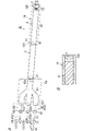
- FIG. 1A is a configuration diagram of a lighting system according to Embodiment 1.
- FIG. 1B is a cross-sectional view of part of the same lighting system.
- FIG. 2 is a cross-sectional view of a wavelength conversion fiber in the same illumination system.
- 3A to 3C are explanatory diagrams of the principle of operation of the same lighting system.
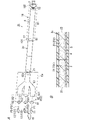
- FIG. 4 is a configuration diagram of a lighting system according to the second embodiment.
- 5A is a configuration diagram of a lighting system according to Embodiment 3.
- FIG. FIG. 5B is a cross-sectional view of part of the same lighting system.
- 6A is a configuration diagram of a lighting system according to Embodiment 4.
- FIG. 6B is a cross-sectional view of part of the same illumination system.
- Embodiment 1 The lighting system 1 according to Embodiment 1 will be described below with reference to FIGS. 1A to 3C.
- the illumination system 1 includes, in a wavelength conversion fiber 2 having a wavelength conversion section 23 including a wavelength conversion element (element), excitation light for exciting the wavelength conversion element.
- P1 and seed light P2 for generating stimulated emission light P3 (see FIG. 3C) from the wavelength conversion element excited by the excitation light P1 are made incident.
- Light including excitation light P1 and stimulated emission light P3 is emitted from the wavelength conversion fiber 2 .
- 3A-3C are explanatory diagrams of the principle of operation of the lighting system 1.
- FIG. The vertical axis in FIGS. 3A, 3B and 3C is electron energy. Also, the upward arrow in FIG. 3A indicates the absorption of the excitation light P1.
- downward arrows in FIG. 3C indicate transitions related to spontaneous emission light or stimulated emission light P3.
- the excitation light P1 incident on the wavelength conversion fiber 2 excites the electron e ⁇ at the ground level E0 (including a plurality of energy levels) of the wavelength conversion element to the excitation level E2. Then, the electron e ⁇ at the excited level E2 transitions to the metastable level E1 having lower energy than the excited level E2.
- the stimulated emission light P3 (P32) is generated.
- Stimulated emission light P3 (P31) is generated when the electron e ⁇ at the stable level E1 transitions to the first energy level.
- the first light source unit 11 emits excitation light P1.
- the two second light source units 12 emit seed light P2 (hereinafter also referred to as external seed light P2) for generating stimulated emission light P3 (see FIG. 3C) from the wavelength conversion element excited by the excitation light P1.
- the lighting system 1 also comprises a flexible protective tube 9 .
- a protective tube 9 surrounds the side surface of the wavelength conversion fiber 2 .
- the illumination system 1 is used, for example, to illuminate the inside of the human body in a medical endoscope for the purpose of observing the inside of a human body cavity or hollow organ, collecting a specimen, treating the patient, or the like. That is, the illumination system 1 is an endoscope illumination system, for example.
- the housing housing the first light source unit 11, the second light source unit 12, and the optical system 6 is positioned outside the human body.
- the insertion portion inserted into the human body in the endoscope includes, for example, the wavelength conversion fiber 2, the output lens 7, and the protective tube 9, and an imaging device (for example, CCD camera), nozzles, treatment tools (for example, forceps, etc.).
- the wavelength-converting fiber 2 is an optical fiber containing a wavelength-converting element in the core 3 .
- the wavelength conversion fiber 2 has a core 3, a clad 4, and a covering portion 5, as shown in FIG.
- the clad 4 covers the outer peripheral surface (side surface) of the core 3 .
- the covering portion 5 covers the outer peripheral surface (side surface) of the clad 4 .
- the core 3 has a circular cross-sectional shape perpendicular to the optical axis direction.
- the clad 4 is arranged coaxially with the core 3 .
- the core 3 has a first end face and a second end face opposite to the first end face in the length direction of the core 3 .
- Core 3 includes a translucent material and a wavelength converting element.
- the concentration of wavelength converting elements in the core 3 may or may not be substantially uniform over the entire length of the core 3 .
- the refractive index of the core 3 is substantially the same as the refractive index of the translucent material, which is the main component of the core 3 .
- the translucent material is, for example, fluoride, oxide, or nitride.
- Fluoride is, for example, fluoride glass.
- the oxide is, for example, silicon oxide, quartz, or the like.
- the wavelength converting element is a rare earth element.
- the wavelength conversion element includes, for example, elements selected from the group of Pr, Tb, Ho, Dy, Er, Eu, Nd and Mn.
- the wavelength conversion element is contained in the core 3 as rare earth element ions, such as Pr ions (Pr 3+ ) and Tb ions (Tb 3+ ).
- the wavelength conversion element is excited by pumping light P1, or by amplified spontaneous emission light emitted from a wavelength conversion element other than itself as internal seed light, that is, amplified spontaneous emission light (ASE).
- ASE amplified spontaneous emission light
- the wavelength converting element emits an element-specific ASE of the wavelength converting element, together with stimulated emission light of the same wavelength as the wavelength of the external seed light P2, which together generate the stimulated emission It is emitted as light P3.
- the wavelengths of the ASE and the external seed light P2 are longer than the wavelength of the excitation light P1 (eg, 440-450 nm).
- the wavelength of the seed light P2 will be described in the section "(2.3) Second light source section".
- Pr 3+ is a wavelength conversion element that can emit amplified light of ASE or seed light in the cyan to red range.
- the intensity of stimulated emission light depends on the intensity of internal seed light (spontaneous emission light) and external seed light.
- Tb 3+ can absorb ASE from Pr 3+ and be excited to generate ASE with a wavelength characteristic of Tb 3+ .
- the refractive index of the clad 4 is smaller than that of the core 3.
- the cladding 4 does not contain the wavelength converting elements that the core 3 contains.
- the material of the covering portion 5 is, for example, resin.
- the outer diameter of the covering portion 5 is preferably 1 mm or less.
- the wavelength conversion fiber 2 has a light input portion 21, a light output portion 22, and a wavelength conversion portion 23.
- the light incident portion 21 is a portion on which the pumping light P1 is incident, and includes, for example, the first end surface of the core 3 .
- the light emitting portion 22 includes the second end surface of the core 3 from which light including the excitation light P1 and the stimulated emission light P3 including ASE is emitted.
- the light incidence section 21 may include a reflection reduction section that reduces reflection of the excitation light P1 entering the light incidence section 21 from the outside of the wavelength conversion fiber 2 .
- the reflection reducer may be, for example, an antireflection coat that covers the first end surface of the core 3 .
- the wavelength converting section 23 is provided between the light incident section 21 and the light emitting section 22 .
- the wavelength conversion unit 23 includes a wavelength conversion element that is excited by the excitation light P1 and emits light having a longer wavelength than the excitation light P1.
- the wavelength conversion element is an element capable of absorbing the excitation light P1 and amplifying the spontaneous emission light or seed light P2 having a longer wavelength than the excitation light P1 by stimulated emission. That is, the wavelength conversion element can be excited by the excitation light P1 to generate spontaneous emission light having a longer wavelength than the excitation light P1, and can be excited by the amplified spontaneous emission light.
- the diameter of the core 3 is, for example, 25 ⁇ m or more and 500 ⁇ m or less.
- the length of the wavelength converting portion 23 it is preferable that the lower the concentration of the wavelength converting elements in the wavelength converting portion 23, the longer the length.
- the numerical aperture of the wavelength conversion fiber 2 is, for example, 0.22.
- the concentration of the wavelength converting elements in the wavelength converting portion 23 is the concentration of the wavelength converting elements in the core 3 .
- the first light source section 11 emits excitation light P1 for exciting the wavelength conversion element included in the wavelength conversion section 23 of the wavelength conversion fiber 2 .
- the excitation light P1 emitted from the first light source section 11 is incident on the light incident section 21 of the wavelength conversion fiber 2 via the optical system 6 .
- the wavelength of the excitation light P1 is preferably 350 nm or more and 500 nm or less.
- the first light source unit 11 includes, for example, a laser light source.
- the laser light source emits laser light.
- the excitation light P ⁇ b>1 laser light emitted from the laser light source
- the laser light source is, for example, a semiconductor laser that emits blue laser light.
- the wavelength of the excitation light P1 is, for example, 440 nm or more and 450 nm or less.
- the second light source section 12 emits seed light P2.
- the seed light P2 emitted from the second light source section 12 is incident on the light incident section 21 of the wavelength conversion fiber 2 via the optical system 6 .
- the lighting system 1 includes a plurality of (for example, two) second light source units 12 .
- the two second light source units 12 emit, for example, seed light P2 of one wavelength different from each other.
- one second light source unit 12 out of the two second light source units 12 will be referred to as a second light source unit 121, and the remaining one second light source unit 12 will be referred to as a second light source unit 122.
- the second light source unit 121 is, for example, a semiconductor laser that emits green light.
- the second light source unit 122 is, for example, a semiconductor laser that emits red light.
- the wavelength of the green seed light P21 is preferably about 520 nm, and the wavelength of the red seed light P22 is preferably about 640 nm, for example.
- Each second light source unit 12 is a light source that emits quasi-monochromatic light.
- quasi-monochromatic light is light within a narrow wavelength range (for example, 10 nm).
- the number of the second light source units 12 in the lighting system 1 is not limited to two, and may be three or more, or one.
- the three second light source units 12 are a semiconductor laser that emits green light, a semiconductor laser that emits red light, and a semiconductor laser that emits orange light. and a semiconductor laser that emits light.
- the wavelength of the orange seed light is preferably about 600 nm, for example.
- the light emitted from the second light source section 121 enters the light incident section 21 of the wavelength conversion fiber 2 via the optical system 6 as seed light P2 (P21). Also, the light emitted from the second light source section 122 enters the light incident section 21 of the wavelength conversion fiber 2 via the optical system 6 as seed light P2 (P22).
- the optical system 6 includes excitation light P1 emitted from the first light source unit 11, seed light P2 (P21) emitted from the second light source unit 121, and light emitted from the second light source unit 122. Seed light P2 (P22) is caused to enter the light incident portion 21. As shown in FIG.
- the optical system 6 constitutes an optical coupling section for making the excitation light P1 and each seed light P2 incident on the light incidence section 21 of the wavelength conversion fiber 2 .
- the optical system 6 includes a first condenser lens 61 and two second condenser lenses 62 .
- the first condenser lens 61 condenses the excitation light P1 emitted from the first light source section 11 .
- the two second condenser lenses 62 correspond to the two second light source units 12 one-to-one, and collect the seed light P2 emitted from the corresponding second light source units 12 .
- the second condenser lens 62 corresponding to the second light source section 121 will be referred to as the second condenser lens 621
- the second condenser lens 62 corresponding to the second light source section 122 will be referred to as the second condenser lens.
- lens 622 Also referred to as lens 622 .
- the first condenser lens 61 is arranged between the first light source section 11 and the light incident section 21 of the wavelength conversion fiber 2, and directs the excitation light P1 emitted from the first light source section 11 to the light incident section 21. Concentrate.
- the first condenser lens 61 is, for example, a biconvex lens, but is not limited to this, and may be, for example, a Fresnel lens.
- the second condenser lens 621 is arranged between the second light source section 121 and the light incident section 21 of the wavelength conversion fiber 2, and directs the seed light P21 emitted from the second light source section 121 to the light incident section 21. Concentrate.
- the second condenser lens 621 is, for example, a biconvex lens, but is not limited to this, and may be, for example, a Fresnel lens.
- the second condenser lens 622 is arranged between the second light source section 122 and the light incident section 21 of the wavelength conversion fiber 2, and directs the seed light P22 emitted from the second light source section 122 to the light incident section 21. Concentrate.
- the second condenser lens 622 is, for example, a biconvex lens, but is not limited to this, and may be, for example, a Fresnel lens.
- the optical system 6 may include a first collimating lens arranged between the first light source section 11 and the first condenser lens 61 to collimate the excitation light P1 from the first light source section 11 . Further, the optical system 6 may include a second collimating lens arranged between the second light source section 121 and the second condenser lens 621 to collimate the seed light P21 from the second light source section 121 . The optical system 6 may also include a second collimating lens that is arranged between the second light source section 122 and the second condenser lens 622 to collimate the seed light P22 from the second light source section 122 .
- the emission lens 7 collects the light emitted from the light emission section 22 .
- the exit lens 7 emits the light from the wavelength conversion fiber 2 .
- the output lens 7 constitutes an objective lens.
- the exit lens 7 is, for example, a biconvex lens.
- the output lens 7 is held by a protective tube 9 .
- the output lens 7 is arranged inside the protective tube 9 and faces the light output portion 22 of the wavelength conversion fiber 2 .
- the protective tube 9 protects the wavelength conversion fiber 2 .
- the material of the protective tube 9 is metal, for example.
- the protection tube 9 has flexibility.
- the protective tube 9 has a first end 91 and a second end 92 . In the protective tube 9 , the first end 91 of the protective tube 9 surrounds the light incident portion 21 of the wavelength conversion fiber 2 , and the second end 92 of the protective tube 9 surrounds the light output portion 22 of the wavelength conversion fiber 2 and the output lens 7 . I'm in.
- the lighting system 1 includes a housing that houses the first light source section 11 and two second light source sections 12 .
- the lighting system 1 further includes an adjustment unit 15 .
- the adjuster 15 adjusts the intensity of the seed light P2 of at least one wavelength.
- the adjustment unit 15 adjusts the intensity of the excitation light P1 and the intensity of each of the seed lights P21 and P22.
- the adjustment unit 15 includes a first drive circuit that drives the first light source unit 11, a plurality of second drive circuits that drive the corresponding second light source units 12 in one-to-one correspondence with the plurality of second light source units 12, a control circuit that individually controls the first drive circuit and the plurality of second drive circuits.
- the control circuit individually controls the first driving circuit and the plurality of second driving circuits, thereby adjusting the chromaticity of the light emitted from (the light emitting portion 22 of) the wavelength conversion fiber 2.
- the illumination system 1 is provided with the adjustment unit 15, thereby enabling color toning. Thereby, the illumination system 1 can adjust the color of the light emitted from the emission lens 7 .
- the adjustment unit 15 is housed in the housing described above, it is not limited to this and may not be housed in the housing.
- a power supply voltage is supplied from, for example, a first power supply circuit to the first drive circuit and the plurality of second drive circuits.
- the power supply voltage is supplied to the control circuit from, for example, the second power supply circuit.
- the first power supply circuit and the second power supply circuit are not included in the components of the lighting system 1, but are not limited to this and may be included.
- the first light source section 11 emits the excitation light P1 and the second light source section 12 emits the seed light P2.
- the excitation light P ⁇ b>1 and the seed light P ⁇ b>2 are caused to enter the light incident portion 21 of the wavelength conversion fiber 2 .
- Part of the excitation light P ⁇ b>1 that has entered the light entrance portion 21 is emitted from the light exit portion 22 .
- the light emitted from the light emitting portion 22 of the wavelength conversion fiber 2 includes the excitation light P1, ASE with a wavelength of about 480 nm generated from the wavelength conversion element, and stimulated emission with the same wavelength as the seed light P2.
- the two types of stimulated emission light P31 and P32 that correspond to the two types of seed light P21 and P22 one-to-one and have different wavelengths are, for example, green light and red light, respectively.
- the light (mixed color light) emitted from the light emitting portion 22 of the wavelength conversion fiber 2 is, for example, white light.
- the stimulated emission light P3 (P31) on the lower side is green light
- the stimulated emission light P3 (P32) on the upper side is red light.
- stimulated emission is generated by the spontaneous emission light and the seed light P2, so the pumping light P1 incident on the light incident portion 21 and the stimulated emission light P3 amplified by the stimulated emission are emitted from the light emitting portion 22. do.
- the intensity of the stimulated emission light P3 having the same wavelength as the seed light P21 is the intensity of the seed light P21 incident on the light incident portion 21 from the second light source portion 121. Greater than strength.
- the intensity of the stimulated emission light P3 having the same wavelength as the seed light P22 out of the light emitted from the light emitting portion 22 of the wavelength conversion fiber 2 is the seed light incident on the light incident portion 21 from the second light source portion 122. Greater than the intensity of P22.
- the mixed color light emitted from the light emitting portion 22 of the wavelength conversion fiber 2 is incoherent light.
- the chromaticity, color temperature, color rendering, etc. of the light emitted from the exit lens 7 are determined according to the wavelength of the ASE and the wavelength of the seed light P2. Note that the operation of the illumination system 1 is different from that of a fiber laser that oscillates.
- the wavelength conversion elements that generate heat are dispersed in the core 3 of the wavelength conversion fiber 2, temperature rise during use can be suppressed.
- the adjustment unit 15 adjusts the intensity of the excitation light P1 and the intensity of each of the plurality of seed lights P2. It may be configured to adjust the intensity of the light P2.
- the illumination system 1 includes a wavelength conversion fiber 2, a first light source section 11, two second light source sections 121 and 122, an optical system 6, and an output lens 7. .
- the wavelength conversion fiber 2 has a light input portion 21, a light output portion 22, and a wavelength conversion portion 23 including a wavelength conversion element.
- the wavelength converting section 23 is provided between the light incident section 21 and the light emitting section 22 .
- the wavelength conversion element can be excited by the excitation light P1 to generate spontaneous emission light having a longer wavelength than the excitation light P1, and can be excited by amplified spontaneous emission light.
- the first light source unit 11 emits excitation light P1.
- the second light source units 121 and 122 emit seed lights P21 and P22 for generating stimulated emission lights P31 and P32 from the wavelength conversion elements excited by the pump light P1 or the amplified spontaneous emission light.
- the optical system 6 causes the excitation light P1 emitted from the first light source section 11 and the seed lights P21 and P22 emitted from the two second light source sections 121 and 122 to enter the light incident section 21 .
- the exit lens 7 collects the light emitted from the light exit portion 22 of the wavelength conversion fiber 2 .
- the optical system 6 includes the first condenser lens 61, the second condenser lens 621, and the second condenser lens 621, so that the excitation light P1 and the seed light having different wavelengths It is possible to allow the light P21 and the seed light P22 to enter efficiently, and it is possible to increase the light output.
- the illumination system 1 since the illumination system 1 according to the first embodiment further includes the adjuster 15 that adjusts the intensity of each of the seed lights P2 of a plurality of wavelengths, it is possible to adjust the chromaticity of the light emitted from the exit lens 7.
- the wavelength conversion section 23 contains Pr 3+ as a wavelength conversion element, and not only emits cyan-colored ASE, but also multi-wavelength seed light P2 from the light incidence section. 21, the intensity of each of the green stimulated emission light and the red stimulated emission light can be increased. Thereby, the lighting system 1 according to the first embodiment can improve the color rendering properties of the light emitted from the emission lens 7 .
- the wavelength conversion section 23 since the wavelength conversion section 23 contains Pr 3+ and Tb 3+ as two types of wavelength conversion elements, the color rendering properties of the light emitted from the output lens 7 are further improved. can be improved.
- the combination of the wavelength of the excitation light P1 and the wavelength conversion element may be determined so that visible light and near-infrared light are emitted from the emission lens 7.
- the wavelength of the near-infrared light is, for example, 700 nm or more and 750 nm or less.
- the illumination system 1 according to the first embodiment can be suitably used, for example, as an illumination system for an endoscope that performs ICG (Indocyanine Green) fluorescence observation.
- the combination of the wavelength of the excitation light P1 and the wavelength conversion element may be determined so that the illumination system 1 emits visible light, ultraviolet light, and near-infrared light.
- the wavelength of the ultraviolet light is, for example, 350 nm or more and 380 nm or less.
- the illumination system 1 according to the first embodiment can use, for example, the ultraviolet light emitted from the output lens 7 of the illumination system 1 as therapeutic ultraviolet light in an endoscope.
- the lighting system 1 according to the first embodiment can adjust the output of each of the plurality of seed lights P2 by including the adjustment unit 15, so that for example, it is possible to adjust colors from ultraviolet to near-infrared.
- the lighting system 1 according to the first embodiment can reduce the number of light sources and the number of optical members such as filters.
- the core diameter of the wavelength conversion fiber 2 can be designed to be 1 ⁇ m to 500 ⁇ m, for example. Therefore, in the illumination system 1, the light emitted from the wavelength conversion fiber 2 has a smaller light distribution angle than the light emitted from the phosphor device in the laser illumination device. Therefore, the illumination system 1 can efficiently guide the light emitted from the wavelength conversion fiber 2 to the optical fiber, for example. Therefore, in an endoscope to which the illumination system 1 is applied, it is possible to achieve both a reduction in the diameter of the endoscope and an increase in the light output.
- Embodiment 2 A lighting system 1a according to Embodiment 2 will be described below with reference to FIG. Regarding the lighting system 1a according to the second embodiment, the same components as those of the lighting system 1 according to the first embodiment are denoted by the same reference numerals, and descriptions thereof are omitted.
- the illumination system 1a according to the second embodiment differs from the illumination system 1 according to the first embodiment in that an optical system 6a is provided instead of the optical system 6 in the illumination system 1 according to the first embodiment.
- the optical system 6a includes a first condenser lens 61 and two second condenser lenses 62, and further includes an optical combiner 63.
- the optical combining section 63 is provided between the first condenser lens 61 and the two second condenser lenses 621 and 622 and the light incident section 21 of the wavelength conversion fiber 2 .
- the optical combiner 63 combines the excitation light P1 condensed by the first condensing lens 61, the seed light P21 condensed by the second condensing lens 621, and the seed light P22 condensed by the second condensing lens 622. are combined and made incident on the light incident portion 21 of the wavelength conversion fiber 2 .
- the optical multiplexer 63 is a combiner (multi-wavelength combiner), and includes a first incident section 631 facing the first condenser lens 61 and a second incident section 632 facing the second condenser lens 621. , a second entrance portion 633 facing the second condenser lens 622 and an exit portion 634 facing the light entrance portion 21 of the wavelength conversion fiber 2 .
- the optical multiplexer 63 is not limited to a combiner, and may be, for example, an optical fiber coupler, a waveguide coupler, or the like.
- the illumination system 1a according to the second embodiment causes the excitation light P1 and the seed lights P21 and P22 to enter the light incident portion 21 of the wavelength conversion fiber 2 more efficiently than the illumination system 1 according to the first embodiment. Therefore, the optical output can be increased.
- Embodiment 3 The illumination system 1b according to Embodiment 3 will be described below with reference to FIGS. 5A and 5B.
- the same reference numerals are assigned to the same components as those of the lighting system 1a according to the second embodiment, and the description thereof is omitted.
- the illumination system 1b according to the third embodiment differs from the illumination system 1a according to the second embodiment in that it includes an optical fiber 8. Further, the lighting system 1b according to the third embodiment does not include the protective tube 9 in the lighting system 1a according to the second embodiment, but includes the protective tube 19 for protecting the optical fiber 8. It is different from the illumination system 1a which concerns.
- the optical fiber 8 is provided between the light output portion 22 of the wavelength conversion fiber 2 and the output lens 7 .
- the optical fiber 8 propagates the light emitted from the light emitting portion 22 of the wavelength conversion fiber 2 and emits it toward the emission lens 7 .
- the optical fiber 8 does not have the wavelength converting portion 23 of the wavelength converting fiber 2 . In other words, the optical fiber 8 does not contain any wavelength conversion elements and has no wavelength conversion function.
- the optical fiber 8 is directly connected to the wavelength conversion fiber 2 so that the light from the wavelength conversion fiber 2 is incident.
- An optical fiber 8 is coupled to the wavelength converting fiber 2 .
- the optical fiber 8 has a light entrance portion 81 and a light exit portion 82 .
- the light entrance portion 81 of the optical fiber 8 is fused to the light exit portion 22 of the wavelength conversion fiber 2 .
- the light output portion 82 of the optical fiber 8 faces the output lens 7 .
- the diameter of the core of the optical fiber 8 is preferably equal to or larger than the diameter of the core 3 (see FIG. 2) of the wavelength conversion fiber 2, and is approximately the same as the diameter of the wavelength conversion fiber 2, for example.
- the output lens 7 is held by the protective tube 19.
- the output lens 7 is arranged inside the protective tube 19 and faces the light output portion 82 of the optical fiber 8 .
- the protective tube 19 protects the optical fiber 8.
- the material of the protective tube 19 is metal, for example.
- the protective tube 19 has flexibility.
- Protective tube 19 has a first end 191 and a second end 192 .
- the protective tube 19 surrounds the side 83 of the optical fiber 8 .
- the first end 191 of the protective tube 19 surrounds the light incident portion 81 of the optical fiber 8
- the second end 192 of the protective tube 19 surrounds the light emitting portion 82 of the optical fiber 8 and the output lens 7. .
- the illumination system 1b according to the third embodiment includes a wavelength conversion unit 23 (see FIG. 2) including a wavelength conversion element, a first light source unit 11, and two second light source units. 12 and an output lens 7 .
- a wavelength conversion unit 23 including a wavelength conversion element, a first light source unit 11, and two second light source units. 12 and an output lens 7 .
- the illumination system 1b according to the third embodiment includes the optical fiber 8 provided between the light exit portion 22 of the wavelength conversion fiber 2 and the exit lens 7, the light from the light entrance portion 21 of the wavelength conversion fiber 2 Cost reduction can be achieved when the distance to the output lens 7 is lengthened.
- the illumination system 1b since the illumination system 1b according to the third embodiment includes the optical fiber 8 provided between the light emitting portion 22 of the wavelength conversion fiber 2 and the output lens 7, it is used as an endoscope illumination system, for example.
- the wavelength conversion fiber 2 can be positioned outside the body, and a fiber scope including the optical fiber 8, the exit lens 7 and the protective tube 19 can be inserted into the human body.
- the illumination system 1b can suppress the temperature rise of the fiber scope inserted into the human body.
- Embodiment 4 A lighting system 1c according to Embodiment 4 will be described below with reference to FIGS. 6A and 6B.
- the same components as those of the lighting system 1b according to the third embodiment are denoted by the same reference numerals, and description thereof is omitted.
- an illumination system 1c according to Embodiment 4 includes a wavelength conversion fiber 2c in place of the wavelength conversion fiber 2 in the illumination system 1b according to Embodiment 3, and the wavelength conversion fiber 2c serves as a wavelength conversion unit 23. is different from the lighting system 1b according to the third embodiment in that it has a plurality of (for example, two).
- the wavelength conversion fiber 2 c includes a core 3 , a clad 4 and a covering portion 5 like the wavelength conversion fiber 2 .
- the wavelength conversion elements included in each of the multiple (two) wavelength conversion sections 23 are different from each other.
- a plurality of wavelength conversion units 23 are arranged in the optical axis direction of the core 3 .
- the wavelength conversion portion 23 on the side of the light incidence portion 21 of the light incidence portion 21 of the wavelength conversion fiber 2c and the light emission portion 22 of the wavelength conversion fiber 2c is the first wavelength conversion portion 23.
- the wavelength conversion section 231 is sometimes called the wavelength conversion section 231
- the wavelength conversion section 23 on the side of the light emitting section 22 is sometimes called the second wavelength conversion section 232 .
- the first wavelength conversion section 231 includes, for example, Pr as a wavelength conversion element.
- the second wavelength converter 232 includes, for example, Tb as a wavelength conversion element.
- the combination of the wavelength conversion element of the first wavelength conversion section 231 and the wavelength conversion element of the second wavelength conversion section 232 is two elements selected from the group of Pr, Tb, Ho, Dy, Er, Eu, Nd and Mn. is not limited to the combination of Pr and Tb.
- the length of the first wavelength converting portion 231 and the length of the second wavelength converting portion 232 are the same, but are not limited to this and may be different.
- the illumination system 1c according to Embodiment 4 includes a wavelength conversion section 23 including a wavelength conversion element, a first light source section 11, two second light source sections 12, an optical system 6, and an output lens 7.
- the illumination system 1c according to the fourth embodiment can increase the intensity of light (stimulated emission light P3) having a wavelength different from that of the excitation light P1, like the illumination system 1b according to the third embodiment.
- the wavelength conversion elements included in each of the plurality (two) wavelength conversion units 23 are different from each other, so it is possible to improve the color rendering properties.
- Embodiments 1-4 above are but one of various embodiments of the present disclosure.
- the first to fourth embodiments described above can be modified in various ways according to the design, etc., as long as the object of the present disclosure can be achieved.
- the applications of the lighting systems 1, 1a, 1b, and 1c are not limited to medical endoscopes, and may be, for example, lighting applications, display applications, and illumination applications in industrial endoscopes.
- the lighting systems 1, 1a, 1b, and 1c may be applied to facilities or to mobile bodies.
- Facilities include, for example, warehouses, airports, detached houses, collective housing, office buildings, stores, museums, hotels, factories, and the like.
- Mobile objects include, for example, automobiles, bicycles, trains, airplanes, ships, and drones.
- the laser light source included in the first light source unit 11 is not limited to a semiconductor laser that emits blue laser light, and may be, for example, a semiconductor laser that emits violet laser light. Further, the first light source unit 11 is not limited to a semiconductor laser, and may be configured to include an LED (Light Emitting Diode) light source and an optical system, for example.
- LED Light Emitting Diode
- the second light source unit 121 is not limited to a semiconductor laser that emits green light, and may be an LED that emits green light, for example. Further, the second light source unit 122 is not limited to a semiconductor laser that emits red light, and may be an LED that emits red light, for example.
- the relative positional relationship between the first light source section 11 and the plurality of second light source sections 12 and the light incident section 21 of the wavelength conversion fiber 2 is not limited to the positional relationships in the first to third embodiments.
- the illumination system 1 by arranging a cross dichroic prism as a light source system between the first light source section 11 and the plurality of second light source sections 12 and the light incident section 21 of the wavelength conversion fiber 2, the first light source section 11 and the plurality of second light source sections 12 and the light incident section 21 of the wavelength conversion fiber 2 may be changed.
- the relative positional relationship between the first light source section 11 and the plurality of second light source sections 12 and the light incident section 21 of the wavelength conversion fiber 2c is not limited to the positional relationship in the fourth embodiment.
- the optical system 6 is not limited to the case in which the first condenser lens 61, the second condenser lens 621, and the second condenser lens 622 are separately provided, and one optical system for condensing the excitation light P1 and the plurality of seed lights P2. It may be a condenser lens.
- the illumination systems 1, 1a, and 1b include a plurality of second light source units 12 for one wavelength conversion fiber 2, but this is not restrictive, and at least one It is sufficient if the second light source section 12 is provided.
- the illumination system 1c includes a plurality of second light source units 12 for one wavelength conversion fiber 2c. 12 is sufficient.
- the illumination system (1; 1a; 1b; 1c) includes a wavelength conversion fiber (2; 2c), a first light source section (11), a second light source section (12), an optical system ( 6; 6a) and an exit lens (7).
- a wavelength conversion fiber (2; 2c) has a light input section (21), a light output section (22), and a wavelength conversion section (23) including a wavelength conversion element.
- the wavelength conversion section (23) is provided between the light entrance section (21) and the light exit section (22).
- the wavelength conversion element can be excited by the excitation light (P1) to generate spontaneous emission light having a longer wavelength than the excitation light (P1), and can be excited by the amplified spontaneous emission light.
- the first light source section (11) emits excitation light (P1).
- a second light source section (12) emits seed light (P2) for generating stimulated emission light (P3) from the wavelength conversion element excited by pumping light (P1) or amplified spontaneous emission light.
- the optical system (6; 6a) passes the excitation light (P1) emitted from the first light source (11) and the seed light (P2) emitted from the second light source (12) to a light incident part (21). incident on the
- the exit lens (7) collects the light emitted from the light exit part (22).
- the lighting system (1; 1a; 1b; 1c) it is possible to increase the intensity of the light (stimulated emission light P3) having a wavelength different from that of the excitation light (P1).
- the optical system (6; 6a) includes a first condenser lens (61) and a second condenser lens ( 62) and
- the first condenser lens (61) condenses the excitation light (P1) emitted from the first light source section (11).
- the second condenser lens (62) condenses the seed light (P2) emitted from the second light source section (12).
- the excitation light (P1) and the seed light (P2) are directed to the light incident part (21) of the wavelength conversion fiber (2; 2c). Efficient incidence is possible, and a high optical output can be achieved.
- the optical system (6a) further includes an optical combiner (63).
- the optical combining section (63) is provided between the first condenser lens (61) and the second condenser lens (62) and the light entrance section (21) of the wavelength conversion fiber (2; 2c).
- An optical combiner (63) multiplexes the excitation light (P1) condensed by the first condensing lens (61) and the seed light (P2) condensed by the second condensing lens (62). to enter the light incident portion (21).
- the excitation light (P1) and the seed light (P2) are more efficiently directed to the light entrance portion (21) of the wavelength conversion fiber (2; 2c). It is possible to make the light incident on the laser beam, and the light output can be increased.
- the illumination system (1b; 1c) in any one of the first to third aspects, further comprises an optical fiber (8).
- the optical fiber (8) is provided between the light exit portion (22) of the wavelength conversion fiber (2; 2c) and the exit lens (7).
- the optical fiber (8) propagates the light emitted from the light emitting portion (22) of the wavelength conversion fiber (2; 2c) and emits the light toward the emission lens (7).
- the illumination system (1b; 1c) aims at cost reduction when lengthening the distance from the light incident part (21) of the wavelength conversion fiber (2; 2c) to the output lens (7). becomes possible.
- the lighting system (1b; 1c) according to the fifth aspect, in the fourth aspect, further comprises a flexible protective tube (19).
- a protective tube (19) surrounds the sides (83) of the optical fiber (8).
- the exit lens (7) is held in a protective tube (19).
- the wavelength conversion fiber (2c) has a plurality of wavelength conversion parts (23).
- the wavelength conversion elements included in each of the plurality of wavelength conversion units (23) are different from each other.
- the first light source section (11) includes a laser light source.
- the intensity of the excitation light (P1) can be increased.
- the lighting system (1; 1a; 1b; 1c) according to the eighth aspect includes a plurality of second light source units (12) in any one of the first to seventh aspects.
- a plurality of second light source units (12) output a plurality of seed lights (P2).
- the plurality of seed lights (P2) output from the plurality of second light source units (12) have different wavelengths.
- the light including the plurality of stimulated emission lights (P3) corresponding to the plurality of seed lights (P2) on a one-to-one basis is transmitted through the wavelength conversion fiber (2;
- the light can be emitted from 2c), and the color rendering can be improved.
- the second light source section (12) includes a laser light source.
- the illumination system (1; 1a; 1b; 1c) according to the ninth aspect can increase the intensity of the seed light (P2).
- the wavelength conversion element comprises Pr, Tb, Ho, Dy, Er, Eu, Nd and one or more elements selected from the group of Mn.
- excitation by spontaneous emission amplified light from at least one element causes another Amplified spontaneous emission light at different wavelengths from the element can also be generated.
- the light emitted from the light emitting portion (22) of the wavelength conversion fiber (2; 2c) is in the wavelength range of 350 nm or more and 750 nm or less.
- Reference Signs List 1 1a, 1b, 1c illumination system 2, 2c wavelength conversion fiber 21 light input section 22 light output section 23 wavelength conversion section 6, 6a optical system 61 first condenser lens 62 second condenser lens 621 second condenser lens 622 second condenser lens 63 light combining section 7 output lens 8 optical fiber 83 side surface 9 protection tube 11 first light source section 12 second light source section 121 second light source section 122 second light source section 15 adjustment section 19 protection tube P1 excitation light P2 Seed light P21 Seed light P22 Seed light P3 Stimulated emission light P31 Stimulated emission light P32 Stimulated emission light
Landscapes
- Engineering & Computer Science (AREA)
- Physics & Mathematics (AREA)
- Optics & Photonics (AREA)
- Microelectronics & Electronic Packaging (AREA)
- General Engineering & Computer Science (AREA)
- Electromagnetism (AREA)
- Plasma & Fusion (AREA)
- Optical Couplings Of Light Guides (AREA)
Priority Applications (2)
| Application Number | Priority Date | Filing Date | Title |
|---|---|---|---|
| JP2023520853A JP7620949B2 (ja) | 2021-05-14 | 2022-03-10 | 照明システム |
| US18/289,566 US12422109B2 (en) | 2021-05-14 | 2022-03-10 | Lighting system |
Applications Claiming Priority (2)
| Application Number | Priority Date | Filing Date | Title |
|---|---|---|---|
| JP2021-082735 | 2021-05-14 | ||
| JP2021082735 | 2021-05-14 |
Publications (1)
| Publication Number | Publication Date |
|---|---|
| WO2022239436A1 true WO2022239436A1 (ja) | 2022-11-17 |
Family
ID=84029140
Family Applications (1)
| Application Number | Title | Priority Date | Filing Date |
|---|---|---|---|
| PCT/JP2022/010526 Ceased WO2022239436A1 (ja) | 2021-05-14 | 2022-03-10 | 照明システム |
Country Status (3)
| Country | Link |
|---|---|
| US (1) | US12422109B2 (https=) |
| JP (1) | JP7620949B2 (https=) |
| WO (1) | WO2022239436A1 (https=) |
Families Citing this family (1)
| Publication number | Priority date | Publication date | Assignee | Title |
|---|---|---|---|---|
| US12571506B2 (en) * | 2024-02-08 | 2026-03-10 | Flex-N-Gate Advanced Product Development, Llc | Multi-function light pipe |
Citations (5)
| Publication number | Priority date | Publication date | Assignee | Title |
|---|---|---|---|---|
| JP2007027388A (ja) * | 2005-07-15 | 2007-02-01 | Sumitomo Electric Ind Ltd | 光源装置および光照射装置 |
| JP2009266463A (ja) * | 2008-04-23 | 2009-11-12 | Panasonic Corp | 面状照明装置とこれを用いた画像表示装置 |
| JP2018195627A (ja) * | 2017-05-12 | 2018-12-06 | パナソニックIpマネジメント株式会社 | 光源装置および照明器具 |
| US20200194962A1 (en) * | 2018-12-17 | 2020-06-18 | Industrial Technology Research Institute | Laser device |
| WO2021014853A1 (ja) * | 2019-07-19 | 2021-01-28 | 公益財団法人レーザー技術総合研究所 | 発光装置及び光ファイバ |
Family Cites Families (6)
| Publication number | Priority date | Publication date | Assignee | Title |
|---|---|---|---|---|
| WO2007007388A1 (ja) * | 2005-07-11 | 2007-01-18 | Mitsubishi Denki Kabushiki Kaisha | 照明装置 |
| JP4699131B2 (ja) | 2005-08-05 | 2011-06-08 | 株式会社フジクラ | 光ファイバレーザ、光ファイバ増幅器、mopa方式光ファイバレーザ |
| JP5103874B2 (ja) | 2006-11-15 | 2012-12-19 | 日亜化学工業株式会社 | 発光装置 |
| JP5019289B2 (ja) * | 2007-08-10 | 2012-09-05 | オリンパス株式会社 | 光ファイバ照明装置 |
| JP2012243789A (ja) | 2011-05-16 | 2012-12-10 | Miyachi Technos Corp | ファイバレーザ加工装置及びレーザ加工方法 |
| US9250390B2 (en) * | 2011-12-09 | 2016-02-02 | Lumentum Operations Llc | Varying beam parameter product of a laser beam |
-
2022
- 2022-03-10 US US18/289,566 patent/US12422109B2/en active Active
- 2022-03-10 WO PCT/JP2022/010526 patent/WO2022239436A1/ja not_active Ceased
- 2022-03-10 JP JP2023520853A patent/JP7620949B2/ja active Active
Patent Citations (5)
| Publication number | Priority date | Publication date | Assignee | Title |
|---|---|---|---|---|
| JP2007027388A (ja) * | 2005-07-15 | 2007-02-01 | Sumitomo Electric Ind Ltd | 光源装置および光照射装置 |
| JP2009266463A (ja) * | 2008-04-23 | 2009-11-12 | Panasonic Corp | 面状照明装置とこれを用いた画像表示装置 |
| JP2018195627A (ja) * | 2017-05-12 | 2018-12-06 | パナソニックIpマネジメント株式会社 | 光源装置および照明器具 |
| US20200194962A1 (en) * | 2018-12-17 | 2020-06-18 | Industrial Technology Research Institute | Laser device |
| WO2021014853A1 (ja) * | 2019-07-19 | 2021-01-28 | 公益財団法人レーザー技術総合研究所 | 発光装置及び光ファイバ |
Also Published As
| Publication number | Publication date |
|---|---|
| US12422109B2 (en) | 2025-09-23 |
| JP7620949B2 (ja) | 2025-01-24 |
| JPWO2022239436A1 (https=) | 2022-11-17 |
| US20240302004A1 (en) | 2024-09-12 |
Similar Documents
| Publication | Publication Date | Title |
|---|---|---|
| US7780326B2 (en) | Optical fiber lighting apparatus | |
| US10058231B2 (en) | Lighting structure and endoscope | |
| JP4925618B2 (ja) | 光源装置および該光源装置を備える内視鏡 | |
| US11868023B2 (en) | Light-emitting device and optical fiber | |
| JP6868807B2 (ja) | 光源装置および照明器具 | |
| US7020378B2 (en) | Device for producing a white light | |
| US10548466B2 (en) | Light source module and endoscope light source system | |
| US9835782B2 (en) | Irradiation module having light guides | |
| CN103988014A (zh) | 具有多个导光路径的光源系统 | |
| JP2005347223A (ja) | 光源装置 | |
| JP4375270B2 (ja) | 発光装置 | |
| JP2009277734A (ja) | 半導体光源装置 | |
| JP7458039B2 (ja) | 発光システム | |
| JP7620949B2 (ja) | 照明システム | |
| JP6596582B2 (ja) | 照明装置 | |
| JP2010017305A (ja) | 光源装置およびこれを用いた内視鏡装置 | |
| JP5480929B2 (ja) | 内視鏡用投光ユニット | |
| CN211293329U (zh) | 照明装置 | |
| JP5675911B2 (ja) | 光ファイバ照明装置 | |
| CN114206197B (zh) | 光学装置、无线内窥镜及内窥镜系统 | |
| JP2007275199A (ja) | 観察装置及び内視鏡装置 | |
| JP2007275198A (ja) | 光源装置及び内視鏡システム |
Legal Events
| Date | Code | Title | Description |
|---|---|---|---|
| 121 | Ep: the epo has been informed by wipo that ep was designated in this application |
Ref document number: 22807143 Country of ref document: EP Kind code of ref document: A1 |
|
| WWE | Wipo information: entry into national phase |
Ref document number: 2023520853 Country of ref document: JP |
|
| NENP | Non-entry into the national phase |
Ref country code: DE |
|
| 122 | Ep: pct application non-entry in european phase |
Ref document number: 22807143 Country of ref document: EP Kind code of ref document: A1 |
|
| WWG | Wipo information: grant in national office |
Ref document number: 18289566 Country of ref document: US |