WO2022239436A1 - Lighting system - Google Patents
Lighting system Download PDFInfo
- Publication number
- WO2022239436A1 WO2022239436A1 PCT/JP2022/010526 JP2022010526W WO2022239436A1 WO 2022239436 A1 WO2022239436 A1 WO 2022239436A1 JP 2022010526 W JP2022010526 W JP 2022010526W WO 2022239436 A1 WO2022239436 A1 WO 2022239436A1
- Authority
- WO
- WIPO (PCT)
- Prior art keywords
- light
- wavelength conversion
- light source
- wavelength
- seed
- Prior art date
Links
- 239000000835 fiber Substances 0.000 claims abstract description 98
- 230000003287 optical effect Effects 0.000 claims abstract description 52
- 230000002269 spontaneous effect Effects 0.000 claims abstract description 25
- 238000006243 chemical reaction Methods 0.000 claims description 165
- 238000005286 illumination Methods 0.000 claims description 89
- 230000005284 excitation Effects 0.000 claims description 76
- 239000013307 optical fiber Substances 0.000 claims description 35
- 230000001681 protective effect Effects 0.000 claims description 31
- 229910052777 Praseodymium Inorganic materials 0.000 claims description 5
- 229910052771 Terbium Inorganic materials 0.000 claims description 5
- 229910052692 Dysprosium Inorganic materials 0.000 claims description 4
- 229910052691 Erbium Inorganic materials 0.000 claims description 4
- 229910052693 Europium Inorganic materials 0.000 claims description 4
- 229910052689 Holmium Inorganic materials 0.000 claims description 4
- 229910052779 Neodymium Inorganic materials 0.000 claims description 4
- 229910052748 manganese Inorganic materials 0.000 claims description 3
- 239000004065 semiconductor Substances 0.000 description 12
- 239000000463 material Substances 0.000 description 7
- 238000010586 diagram Methods 0.000 description 6
- 238000009877 rendering Methods 0.000 description 6
- OAICVXFJPJFONN-UHFFFAOYSA-N Phosphorus Chemical compound [P] OAICVXFJPJFONN-UHFFFAOYSA-N 0.000 description 4
- 230000005540 biological transmission Effects 0.000 description 4
- 238000005086 pumping Methods 0.000 description 4
- 230000007704 transition Effects 0.000 description 4
- 239000012141 concentrate Substances 0.000 description 3
- 150000002500 ions Chemical class 0.000 description 3
- KRHYYFGTRYWZRS-UHFFFAOYSA-M Fluoride anion Chemical compound [F-] KRHYYFGTRYWZRS-UHFFFAOYSA-M 0.000 description 2
- VYPSYNLAJGMNEJ-UHFFFAOYSA-N Silicium dioxide Chemical compound O=[Si]=O VYPSYNLAJGMNEJ-UHFFFAOYSA-N 0.000 description 2
- 238000010521 absorption reaction Methods 0.000 description 2
- 238000005253 cladding Methods 0.000 description 2
- MOFVSTNWEDAEEK-UHFFFAOYSA-M indocyanine green Chemical compound [Na+].[O-]S(=O)(=O)CCCCN1C2=CC=C3C=CC=CC3=C2C(C)(C)C1=CC=CC=CC=CC1=[N+](CCCCS([O-])(=O)=O)C2=CC=C(C=CC=C3)C3=C2C1(C)C MOFVSTNWEDAEEK-UHFFFAOYSA-M 0.000 description 2
- 229960004657 indocyanine green Drugs 0.000 description 2
- 229910052751 metal Inorganic materials 0.000 description 2
- 239000002184 metal Substances 0.000 description 2
- 230000002093 peripheral effect Effects 0.000 description 2
- 229910052761 rare earth metal Inorganic materials 0.000 description 2
- 239000003638 chemical reducing agent Substances 0.000 description 1
- 239000003086 colorant Substances 0.000 description 1
- 230000008878 coupling Effects 0.000 description 1
- 238000010168 coupling process Methods 0.000 description 1
- 238000005859 coupling reaction Methods 0.000 description 1
- 239000005383 fluoride glass Substances 0.000 description 1
- 238000003384 imaging method Methods 0.000 description 1
- 238000003780 insertion Methods 0.000 description 1
- 230000037431 insertion Effects 0.000 description 1
- 238000012986 modification Methods 0.000 description 1
- 230000004048 modification Effects 0.000 description 1
- 150000004767 nitrides Chemical class 0.000 description 1
- 210000000056 organ Anatomy 0.000 description 1
- 230000002250 progressing effect Effects 0.000 description 1
- 230000001902 propagating effect Effects 0.000 description 1
- 239000010453 quartz Substances 0.000 description 1
- 239000011347 resin Substances 0.000 description 1
- 229920005989 resin Polymers 0.000 description 1
- 229910052814 silicon oxide Inorganic materials 0.000 description 1
- 230000001225 therapeutic effect Effects 0.000 description 1
Images


Classifications
-
- H—ELECTRICITY
- H01—ELECTRIC ELEMENTS
- H01S—DEVICES USING THE PROCESS OF LIGHT AMPLIFICATION BY STIMULATED EMISSION OF RADIATION [LASER] TO AMPLIFY OR GENERATE LIGHT; DEVICES USING STIMULATED EMISSION OF ELECTROMAGNETIC RADIATION IN WAVE RANGES OTHER THAN OPTICAL
- H01S3/00—Lasers, i.e. devices using stimulated emission of electromagnetic radiation in the infrared, visible or ultraviolet wave range
- H01S3/05—Construction or shape of optical resonators; Accommodation of active medium therein; Shape of active medium
- H01S3/06—Construction or shape of active medium
- H01S3/063—Waveguide lasers, i.e. whereby the dimensions of the waveguide are of the order of the light wavelength
- H01S3/067—Fibre lasers
-
- H—ELECTRICITY
- H01—ELECTRIC ELEMENTS
- H01S—DEVICES USING THE PROCESS OF LIGHT AMPLIFICATION BY STIMULATED EMISSION OF RADIATION [LASER] TO AMPLIFY OR GENERATE LIGHT; DEVICES USING STIMULATED EMISSION OF ELECTROMAGNETIC RADIATION IN WAVE RANGES OTHER THAN OPTICAL
- H01S3/00—Lasers, i.e. devices using stimulated emission of electromagnetic radiation in the infrared, visible or ultraviolet wave range
- H01S3/10—Controlling the intensity, frequency, phase, polarisation or direction of the emitted radiation, e.g. switching, gating, modulating or demodulating
Definitions
- the present disclosure relates generally to lighting systems, and more particularly to lighting systems that utilize excitation light.
- a light source device described in Patent Document 1 includes a solid-state light source and an optical transmission fiber.
- the optical transmission fiber has a first end face and a second end face, and excitation light emitted from the solid-state light source is introduced from the first end face.
- the optical transmission fiber has a wavelength converting core, a light guiding core and a cladding.
- the wavelength-converting core includes a wavelength-converting material that absorbs excitation light to generate a population inversion state of electrons and emits wavelength-converted light in the visible region.
- the light guide core covers the wavelength conversion core and transmits the wavelength-converted light from the first end face side to the second end face side.
- the clad covers the periphery of the light guiding core.
- the optical transmission fiber is configured such that stimulated emission is generated by the wavelength-converted light propagating through the light guide core, and the excitation light emitted from the solid-state light source and the wavelength-converted light amplified by the stimulated emission are emitted from the second end surface.
- An object of the present disclosure is to provide an illumination system capable of increasing the intensity of light with a wavelength different from that of excitation light.
- An illumination system includes a wavelength conversion fiber, a first light source section, a second light source section, an optical system, and an output lens.
- the wavelength conversion fiber has a light input section, a light output section, and a wavelength conversion section including a wavelength conversion element.
- the wavelength converting section is provided between the light incident section and the light emitting section.
- the wavelength conversion element can be excited by excitation light to generate spontaneous emission light having a longer wavelength than the excitation light, and can be excited by amplified spontaneous emission light.
- the first light source section emits the excitation light.
- the second light source unit emits seed light for generating stimulated emission light from the wavelength conversion element excited by the excitation light or the amplified spontaneous emission light.
- the optical system causes the excitation light emitted from the first light source section and the seed light emitted from the second light source section to enter the light incident section.
- the exit lens collects the light emitted from the light exit section.
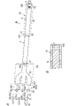
- FIG. 1A is a configuration diagram of a lighting system according to Embodiment 1.
- FIG. 1B is a cross-sectional view of part of the same lighting system.
- FIG. 2 is a cross-sectional view of a wavelength conversion fiber in the same illumination system.
- 3A to 3C are explanatory diagrams of the principle of operation of the same lighting system.
- FIG. 4 is a configuration diagram of a lighting system according to the second embodiment.
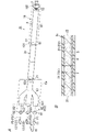
- 5A is a configuration diagram of a lighting system according to Embodiment 3.
- FIG. FIG. 5B is a cross-sectional view of part of the same lighting system.
- 6A is a configuration diagram of a lighting system according to Embodiment 4.
- FIG. 6B is a cross-sectional view of part of the same illumination system.
- Embodiment 1 The lighting system 1 according to Embodiment 1 will be described below with reference to FIGS. 1A to 3C.
- the illumination system 1 includes, in a wavelength conversion fiber 2 having a wavelength conversion section 23 including a wavelength conversion element (element), excitation light for exciting the wavelength conversion element.
- P1 and seed light P2 for generating stimulated emission light P3 (see FIG. 3C) from the wavelength conversion element excited by the excitation light P1 are made incident.
- Light including excitation light P1 and stimulated emission light P3 is emitted from the wavelength conversion fiber 2 .
- 3A-3C are explanatory diagrams of the principle of operation of the lighting system 1.
- FIG. The vertical axis in FIGS. 3A, 3B and 3C is electron energy. Also, the upward arrow in FIG. 3A indicates the absorption of the excitation light P1.
- downward arrows in FIG. 3C indicate transitions related to spontaneous emission light or stimulated emission light P3.
- the excitation light P1 incident on the wavelength conversion fiber 2 excites the electron e ⁇ at the ground level E0 (including a plurality of energy levels) of the wavelength conversion element to the excitation level E2. Then, the electron e ⁇ at the excited level E2 transitions to the metastable level E1 having lower energy than the excited level E2.
- the stimulated emission light P3 (P32) is generated.
- Stimulated emission light P3 (P31) is generated when the electron e ⁇ at the stable level E1 transitions to the first energy level.
- the first light source unit 11 emits excitation light P1.
- the two second light source units 12 emit seed light P2 (hereinafter also referred to as external seed light P2) for generating stimulated emission light P3 (see FIG. 3C) from the wavelength conversion element excited by the excitation light P1.
- the lighting system 1 also comprises a flexible protective tube 9 .
- a protective tube 9 surrounds the side surface of the wavelength conversion fiber 2 .
- the illumination system 1 is used, for example, to illuminate the inside of the human body in a medical endoscope for the purpose of observing the inside of a human body cavity or hollow organ, collecting a specimen, treating the patient, or the like. That is, the illumination system 1 is an endoscope illumination system, for example.
- the housing housing the first light source unit 11, the second light source unit 12, and the optical system 6 is positioned outside the human body.
- the insertion portion inserted into the human body in the endoscope includes, for example, the wavelength conversion fiber 2, the output lens 7, and the protective tube 9, and an imaging device (for example, CCD camera), nozzles, treatment tools (for example, forceps, etc.).
- the wavelength-converting fiber 2 is an optical fiber containing a wavelength-converting element in the core 3 .
- the wavelength conversion fiber 2 has a core 3, a clad 4, and a covering portion 5, as shown in FIG.
- the clad 4 covers the outer peripheral surface (side surface) of the core 3 .
- the covering portion 5 covers the outer peripheral surface (side surface) of the clad 4 .
- the core 3 has a circular cross-sectional shape perpendicular to the optical axis direction.
- the clad 4 is arranged coaxially with the core 3 .
- the core 3 has a first end face and a second end face opposite to the first end face in the length direction of the core 3 .
- Core 3 includes a translucent material and a wavelength converting element.
- the concentration of wavelength converting elements in the core 3 may or may not be substantially uniform over the entire length of the core 3 .
- the refractive index of the core 3 is substantially the same as the refractive index of the translucent material, which is the main component of the core 3 .
- the translucent material is, for example, fluoride, oxide, or nitride.
- Fluoride is, for example, fluoride glass.
- the oxide is, for example, silicon oxide, quartz, or the like.
- the wavelength converting element is a rare earth element.
- the wavelength conversion element includes, for example, elements selected from the group of Pr, Tb, Ho, Dy, Er, Eu, Nd and Mn.
- the wavelength conversion element is contained in the core 3 as rare earth element ions, such as Pr ions (Pr 3+ ) and Tb ions (Tb 3+ ).
- the wavelength conversion element is excited by pumping light P1, or by amplified spontaneous emission light emitted from a wavelength conversion element other than itself as internal seed light, that is, amplified spontaneous emission light (ASE).
- ASE amplified spontaneous emission light
- the wavelength converting element emits an element-specific ASE of the wavelength converting element, together with stimulated emission light of the same wavelength as the wavelength of the external seed light P2, which together generate the stimulated emission It is emitted as light P3.
- the wavelengths of the ASE and the external seed light P2 are longer than the wavelength of the excitation light P1 (eg, 440-450 nm).
- the wavelength of the seed light P2 will be described in the section "(2.3) Second light source section".
- Pr 3+ is a wavelength conversion element that can emit amplified light of ASE or seed light in the cyan to red range.
- the intensity of stimulated emission light depends on the intensity of internal seed light (spontaneous emission light) and external seed light.
- Tb 3+ can absorb ASE from Pr 3+ and be excited to generate ASE with a wavelength characteristic of Tb 3+ .
- the refractive index of the clad 4 is smaller than that of the core 3.
- the cladding 4 does not contain the wavelength converting elements that the core 3 contains.
- the material of the covering portion 5 is, for example, resin.
- the outer diameter of the covering portion 5 is preferably 1 mm or less.
- the wavelength conversion fiber 2 has a light input portion 21, a light output portion 22, and a wavelength conversion portion 23.
- the light incident portion 21 is a portion on which the pumping light P1 is incident, and includes, for example, the first end surface of the core 3 .
- the light emitting portion 22 includes the second end surface of the core 3 from which light including the excitation light P1 and the stimulated emission light P3 including ASE is emitted.
- the light incidence section 21 may include a reflection reduction section that reduces reflection of the excitation light P1 entering the light incidence section 21 from the outside of the wavelength conversion fiber 2 .
- the reflection reducer may be, for example, an antireflection coat that covers the first end surface of the core 3 .
- the wavelength converting section 23 is provided between the light incident section 21 and the light emitting section 22 .
- the wavelength conversion unit 23 includes a wavelength conversion element that is excited by the excitation light P1 and emits light having a longer wavelength than the excitation light P1.
- the wavelength conversion element is an element capable of absorbing the excitation light P1 and amplifying the spontaneous emission light or seed light P2 having a longer wavelength than the excitation light P1 by stimulated emission. That is, the wavelength conversion element can be excited by the excitation light P1 to generate spontaneous emission light having a longer wavelength than the excitation light P1, and can be excited by the amplified spontaneous emission light.
- the diameter of the core 3 is, for example, 25 ⁇ m or more and 500 ⁇ m or less.
- the length of the wavelength converting portion 23 it is preferable that the lower the concentration of the wavelength converting elements in the wavelength converting portion 23, the longer the length.
- the numerical aperture of the wavelength conversion fiber 2 is, for example, 0.22.
- the concentration of the wavelength converting elements in the wavelength converting portion 23 is the concentration of the wavelength converting elements in the core 3 .
- the first light source section 11 emits excitation light P1 for exciting the wavelength conversion element included in the wavelength conversion section 23 of the wavelength conversion fiber 2 .
- the excitation light P1 emitted from the first light source section 11 is incident on the light incident section 21 of the wavelength conversion fiber 2 via the optical system 6 .
- the wavelength of the excitation light P1 is preferably 350 nm or more and 500 nm or less.
- the first light source unit 11 includes, for example, a laser light source.
- the laser light source emits laser light.
- the excitation light P ⁇ b>1 laser light emitted from the laser light source
- the laser light source is, for example, a semiconductor laser that emits blue laser light.
- the wavelength of the excitation light P1 is, for example, 440 nm or more and 450 nm or less.
- the second light source section 12 emits seed light P2.
- the seed light P2 emitted from the second light source section 12 is incident on the light incident section 21 of the wavelength conversion fiber 2 via the optical system 6 .
- the lighting system 1 includes a plurality of (for example, two) second light source units 12 .
- the two second light source units 12 emit, for example, seed light P2 of one wavelength different from each other.
- one second light source unit 12 out of the two second light source units 12 will be referred to as a second light source unit 121, and the remaining one second light source unit 12 will be referred to as a second light source unit 122.
- the second light source unit 121 is, for example, a semiconductor laser that emits green light.
- the second light source unit 122 is, for example, a semiconductor laser that emits red light.
- the wavelength of the green seed light P21 is preferably about 520 nm, and the wavelength of the red seed light P22 is preferably about 640 nm, for example.
- Each second light source unit 12 is a light source that emits quasi-monochromatic light.
- quasi-monochromatic light is light within a narrow wavelength range (for example, 10 nm).
- the number of the second light source units 12 in the lighting system 1 is not limited to two, and may be three or more, or one.
- the three second light source units 12 are a semiconductor laser that emits green light, a semiconductor laser that emits red light, and a semiconductor laser that emits orange light. and a semiconductor laser that emits light.
- the wavelength of the orange seed light is preferably about 600 nm, for example.
- the light emitted from the second light source section 121 enters the light incident section 21 of the wavelength conversion fiber 2 via the optical system 6 as seed light P2 (P21). Also, the light emitted from the second light source section 122 enters the light incident section 21 of the wavelength conversion fiber 2 via the optical system 6 as seed light P2 (P22).
- the optical system 6 includes excitation light P1 emitted from the first light source unit 11, seed light P2 (P21) emitted from the second light source unit 121, and light emitted from the second light source unit 122. Seed light P2 (P22) is caused to enter the light incident portion 21. As shown in FIG.
- the optical system 6 constitutes an optical coupling section for making the excitation light P1 and each seed light P2 incident on the light incidence section 21 of the wavelength conversion fiber 2 .
- the optical system 6 includes a first condenser lens 61 and two second condenser lenses 62 .
- the first condenser lens 61 condenses the excitation light P1 emitted from the first light source section 11 .
- the two second condenser lenses 62 correspond to the two second light source units 12 one-to-one, and collect the seed light P2 emitted from the corresponding second light source units 12 .
- the second condenser lens 62 corresponding to the second light source section 121 will be referred to as the second condenser lens 621
- the second condenser lens 62 corresponding to the second light source section 122 will be referred to as the second condenser lens.
- lens 622 Also referred to as lens 622 .
- the first condenser lens 61 is arranged between the first light source section 11 and the light incident section 21 of the wavelength conversion fiber 2, and directs the excitation light P1 emitted from the first light source section 11 to the light incident section 21. Concentrate.
- the first condenser lens 61 is, for example, a biconvex lens, but is not limited to this, and may be, for example, a Fresnel lens.
- the second condenser lens 621 is arranged between the second light source section 121 and the light incident section 21 of the wavelength conversion fiber 2, and directs the seed light P21 emitted from the second light source section 121 to the light incident section 21. Concentrate.
- the second condenser lens 621 is, for example, a biconvex lens, but is not limited to this, and may be, for example, a Fresnel lens.
- the second condenser lens 622 is arranged between the second light source section 122 and the light incident section 21 of the wavelength conversion fiber 2, and directs the seed light P22 emitted from the second light source section 122 to the light incident section 21. Concentrate.
- the second condenser lens 622 is, for example, a biconvex lens, but is not limited to this, and may be, for example, a Fresnel lens.
- the optical system 6 may include a first collimating lens arranged between the first light source section 11 and the first condenser lens 61 to collimate the excitation light P1 from the first light source section 11 . Further, the optical system 6 may include a second collimating lens arranged between the second light source section 121 and the second condenser lens 621 to collimate the seed light P21 from the second light source section 121 . The optical system 6 may also include a second collimating lens that is arranged between the second light source section 122 and the second condenser lens 622 to collimate the seed light P22 from the second light source section 122 .
- the emission lens 7 collects the light emitted from the light emission section 22 .
- the exit lens 7 emits the light from the wavelength conversion fiber 2 .
- the output lens 7 constitutes an objective lens.
- the exit lens 7 is, for example, a biconvex lens.
- the output lens 7 is held by a protective tube 9 .
- the output lens 7 is arranged inside the protective tube 9 and faces the light output portion 22 of the wavelength conversion fiber 2 .
- the protective tube 9 protects the wavelength conversion fiber 2 .
- the material of the protective tube 9 is metal, for example.
- the protection tube 9 has flexibility.
- the protective tube 9 has a first end 91 and a second end 92 . In the protective tube 9 , the first end 91 of the protective tube 9 surrounds the light incident portion 21 of the wavelength conversion fiber 2 , and the second end 92 of the protective tube 9 surrounds the light output portion 22 of the wavelength conversion fiber 2 and the output lens 7 . I'm in.
- the lighting system 1 includes a housing that houses the first light source section 11 and two second light source sections 12 .
- the lighting system 1 further includes an adjustment unit 15 .
- the adjuster 15 adjusts the intensity of the seed light P2 of at least one wavelength.
- the adjustment unit 15 adjusts the intensity of the excitation light P1 and the intensity of each of the seed lights P21 and P22.
- the adjustment unit 15 includes a first drive circuit that drives the first light source unit 11, a plurality of second drive circuits that drive the corresponding second light source units 12 in one-to-one correspondence with the plurality of second light source units 12, a control circuit that individually controls the first drive circuit and the plurality of second drive circuits.
- the control circuit individually controls the first driving circuit and the plurality of second driving circuits, thereby adjusting the chromaticity of the light emitted from (the light emitting portion 22 of) the wavelength conversion fiber 2.
- the illumination system 1 is provided with the adjustment unit 15, thereby enabling color toning. Thereby, the illumination system 1 can adjust the color of the light emitted from the emission lens 7 .
- the adjustment unit 15 is housed in the housing described above, it is not limited to this and may not be housed in the housing.
- a power supply voltage is supplied from, for example, a first power supply circuit to the first drive circuit and the plurality of second drive circuits.
- the power supply voltage is supplied to the control circuit from, for example, the second power supply circuit.
- the first power supply circuit and the second power supply circuit are not included in the components of the lighting system 1, but are not limited to this and may be included.
- the first light source section 11 emits the excitation light P1 and the second light source section 12 emits the seed light P2.
- the excitation light P ⁇ b>1 and the seed light P ⁇ b>2 are caused to enter the light incident portion 21 of the wavelength conversion fiber 2 .
- Part of the excitation light P ⁇ b>1 that has entered the light entrance portion 21 is emitted from the light exit portion 22 .
- the light emitted from the light emitting portion 22 of the wavelength conversion fiber 2 includes the excitation light P1, ASE with a wavelength of about 480 nm generated from the wavelength conversion element, and stimulated emission with the same wavelength as the seed light P2.
- the two types of stimulated emission light P31 and P32 that correspond to the two types of seed light P21 and P22 one-to-one and have different wavelengths are, for example, green light and red light, respectively.
- the light (mixed color light) emitted from the light emitting portion 22 of the wavelength conversion fiber 2 is, for example, white light.
- the stimulated emission light P3 (P31) on the lower side is green light
- the stimulated emission light P3 (P32) on the upper side is red light.
- stimulated emission is generated by the spontaneous emission light and the seed light P2, so the pumping light P1 incident on the light incident portion 21 and the stimulated emission light P3 amplified by the stimulated emission are emitted from the light emitting portion 22. do.
- the intensity of the stimulated emission light P3 having the same wavelength as the seed light P21 is the intensity of the seed light P21 incident on the light incident portion 21 from the second light source portion 121. Greater than strength.
- the intensity of the stimulated emission light P3 having the same wavelength as the seed light P22 out of the light emitted from the light emitting portion 22 of the wavelength conversion fiber 2 is the seed light incident on the light incident portion 21 from the second light source portion 122. Greater than the intensity of P22.
- the mixed color light emitted from the light emitting portion 22 of the wavelength conversion fiber 2 is incoherent light.
- the chromaticity, color temperature, color rendering, etc. of the light emitted from the exit lens 7 are determined according to the wavelength of the ASE and the wavelength of the seed light P2. Note that the operation of the illumination system 1 is different from that of a fiber laser that oscillates.
- the wavelength conversion elements that generate heat are dispersed in the core 3 of the wavelength conversion fiber 2, temperature rise during use can be suppressed.
- the adjustment unit 15 adjusts the intensity of the excitation light P1 and the intensity of each of the plurality of seed lights P2. It may be configured to adjust the intensity of the light P2.
- the illumination system 1 includes a wavelength conversion fiber 2, a first light source section 11, two second light source sections 121 and 122, an optical system 6, and an output lens 7. .
- the wavelength conversion fiber 2 has a light input portion 21, a light output portion 22, and a wavelength conversion portion 23 including a wavelength conversion element.
- the wavelength converting section 23 is provided between the light incident section 21 and the light emitting section 22 .
- the wavelength conversion element can be excited by the excitation light P1 to generate spontaneous emission light having a longer wavelength than the excitation light P1, and can be excited by amplified spontaneous emission light.
- the first light source unit 11 emits excitation light P1.
- the second light source units 121 and 122 emit seed lights P21 and P22 for generating stimulated emission lights P31 and P32 from the wavelength conversion elements excited by the pump light P1 or the amplified spontaneous emission light.
- the optical system 6 causes the excitation light P1 emitted from the first light source section 11 and the seed lights P21 and P22 emitted from the two second light source sections 121 and 122 to enter the light incident section 21 .
- the exit lens 7 collects the light emitted from the light exit portion 22 of the wavelength conversion fiber 2 .
- the optical system 6 includes the first condenser lens 61, the second condenser lens 621, and the second condenser lens 621, so that the excitation light P1 and the seed light having different wavelengths It is possible to allow the light P21 and the seed light P22 to enter efficiently, and it is possible to increase the light output.
- the illumination system 1 since the illumination system 1 according to the first embodiment further includes the adjuster 15 that adjusts the intensity of each of the seed lights P2 of a plurality of wavelengths, it is possible to adjust the chromaticity of the light emitted from the exit lens 7.
- the wavelength conversion section 23 contains Pr 3+ as a wavelength conversion element, and not only emits cyan-colored ASE, but also multi-wavelength seed light P2 from the light incidence section. 21, the intensity of each of the green stimulated emission light and the red stimulated emission light can be increased. Thereby, the lighting system 1 according to the first embodiment can improve the color rendering properties of the light emitted from the emission lens 7 .
- the wavelength conversion section 23 since the wavelength conversion section 23 contains Pr 3+ and Tb 3+ as two types of wavelength conversion elements, the color rendering properties of the light emitted from the output lens 7 are further improved. can be improved.
- the combination of the wavelength of the excitation light P1 and the wavelength conversion element may be determined so that visible light and near-infrared light are emitted from the emission lens 7.
- the wavelength of the near-infrared light is, for example, 700 nm or more and 750 nm or less.
- the illumination system 1 according to the first embodiment can be suitably used, for example, as an illumination system for an endoscope that performs ICG (Indocyanine Green) fluorescence observation.
- the combination of the wavelength of the excitation light P1 and the wavelength conversion element may be determined so that the illumination system 1 emits visible light, ultraviolet light, and near-infrared light.
- the wavelength of the ultraviolet light is, for example, 350 nm or more and 380 nm or less.
- the illumination system 1 according to the first embodiment can use, for example, the ultraviolet light emitted from the output lens 7 of the illumination system 1 as therapeutic ultraviolet light in an endoscope.
- the lighting system 1 according to the first embodiment can adjust the output of each of the plurality of seed lights P2 by including the adjustment unit 15, so that for example, it is possible to adjust colors from ultraviolet to near-infrared.
- the lighting system 1 according to the first embodiment can reduce the number of light sources and the number of optical members such as filters.
- the core diameter of the wavelength conversion fiber 2 can be designed to be 1 ⁇ m to 500 ⁇ m, for example. Therefore, in the illumination system 1, the light emitted from the wavelength conversion fiber 2 has a smaller light distribution angle than the light emitted from the phosphor device in the laser illumination device. Therefore, the illumination system 1 can efficiently guide the light emitted from the wavelength conversion fiber 2 to the optical fiber, for example. Therefore, in an endoscope to which the illumination system 1 is applied, it is possible to achieve both a reduction in the diameter of the endoscope and an increase in the light output.
- Embodiment 2 A lighting system 1a according to Embodiment 2 will be described below with reference to FIG. Regarding the lighting system 1a according to the second embodiment, the same components as those of the lighting system 1 according to the first embodiment are denoted by the same reference numerals, and descriptions thereof are omitted.
- the illumination system 1a according to the second embodiment differs from the illumination system 1 according to the first embodiment in that an optical system 6a is provided instead of the optical system 6 in the illumination system 1 according to the first embodiment.
- the optical system 6a includes a first condenser lens 61 and two second condenser lenses 62, and further includes an optical combiner 63.
- the optical combining section 63 is provided between the first condenser lens 61 and the two second condenser lenses 621 and 622 and the light incident section 21 of the wavelength conversion fiber 2 .
- the optical combiner 63 combines the excitation light P1 condensed by the first condensing lens 61, the seed light P21 condensed by the second condensing lens 621, and the seed light P22 condensed by the second condensing lens 622. are combined and made incident on the light incident portion 21 of the wavelength conversion fiber 2 .
- the optical multiplexer 63 is a combiner (multi-wavelength combiner), and includes a first incident section 631 facing the first condenser lens 61 and a second incident section 632 facing the second condenser lens 621. , a second entrance portion 633 facing the second condenser lens 622 and an exit portion 634 facing the light entrance portion 21 of the wavelength conversion fiber 2 .
- the optical multiplexer 63 is not limited to a combiner, and may be, for example, an optical fiber coupler, a waveguide coupler, or the like.
- the illumination system 1a according to the second embodiment causes the excitation light P1 and the seed lights P21 and P22 to enter the light incident portion 21 of the wavelength conversion fiber 2 more efficiently than the illumination system 1 according to the first embodiment. Therefore, the optical output can be increased.
- Embodiment 3 The illumination system 1b according to Embodiment 3 will be described below with reference to FIGS. 5A and 5B.
- the same reference numerals are assigned to the same components as those of the lighting system 1a according to the second embodiment, and the description thereof is omitted.
- the illumination system 1b according to the third embodiment differs from the illumination system 1a according to the second embodiment in that it includes an optical fiber 8. Further, the lighting system 1b according to the third embodiment does not include the protective tube 9 in the lighting system 1a according to the second embodiment, but includes the protective tube 19 for protecting the optical fiber 8. It is different from the illumination system 1a which concerns.
- the optical fiber 8 is provided between the light output portion 22 of the wavelength conversion fiber 2 and the output lens 7 .
- the optical fiber 8 propagates the light emitted from the light emitting portion 22 of the wavelength conversion fiber 2 and emits it toward the emission lens 7 .
- the optical fiber 8 does not have the wavelength converting portion 23 of the wavelength converting fiber 2 . In other words, the optical fiber 8 does not contain any wavelength conversion elements and has no wavelength conversion function.
- the optical fiber 8 is directly connected to the wavelength conversion fiber 2 so that the light from the wavelength conversion fiber 2 is incident.
- An optical fiber 8 is coupled to the wavelength converting fiber 2 .
- the optical fiber 8 has a light entrance portion 81 and a light exit portion 82 .
- the light entrance portion 81 of the optical fiber 8 is fused to the light exit portion 22 of the wavelength conversion fiber 2 .
- the light output portion 82 of the optical fiber 8 faces the output lens 7 .
- the diameter of the core of the optical fiber 8 is preferably equal to or larger than the diameter of the core 3 (see FIG. 2) of the wavelength conversion fiber 2, and is approximately the same as the diameter of the wavelength conversion fiber 2, for example.
- the output lens 7 is held by the protective tube 19.
- the output lens 7 is arranged inside the protective tube 19 and faces the light output portion 82 of the optical fiber 8 .
- the protective tube 19 protects the optical fiber 8.
- the material of the protective tube 19 is metal, for example.
- the protective tube 19 has flexibility.
- Protective tube 19 has a first end 191 and a second end 192 .
- the protective tube 19 surrounds the side 83 of the optical fiber 8 .
- the first end 191 of the protective tube 19 surrounds the light incident portion 81 of the optical fiber 8
- the second end 192 of the protective tube 19 surrounds the light emitting portion 82 of the optical fiber 8 and the output lens 7. .
- the illumination system 1b according to the third embodiment includes a wavelength conversion unit 23 (see FIG. 2) including a wavelength conversion element, a first light source unit 11, and two second light source units. 12 and an output lens 7 .
- a wavelength conversion unit 23 including a wavelength conversion element, a first light source unit 11, and two second light source units. 12 and an output lens 7 .
- the illumination system 1b according to the third embodiment includes the optical fiber 8 provided between the light exit portion 22 of the wavelength conversion fiber 2 and the exit lens 7, the light from the light entrance portion 21 of the wavelength conversion fiber 2 Cost reduction can be achieved when the distance to the output lens 7 is lengthened.
- the illumination system 1b since the illumination system 1b according to the third embodiment includes the optical fiber 8 provided between the light emitting portion 22 of the wavelength conversion fiber 2 and the output lens 7, it is used as an endoscope illumination system, for example.
- the wavelength conversion fiber 2 can be positioned outside the body, and a fiber scope including the optical fiber 8, the exit lens 7 and the protective tube 19 can be inserted into the human body.
- the illumination system 1b can suppress the temperature rise of the fiber scope inserted into the human body.
- Embodiment 4 A lighting system 1c according to Embodiment 4 will be described below with reference to FIGS. 6A and 6B.
- the same components as those of the lighting system 1b according to the third embodiment are denoted by the same reference numerals, and description thereof is omitted.
- an illumination system 1c according to Embodiment 4 includes a wavelength conversion fiber 2c in place of the wavelength conversion fiber 2 in the illumination system 1b according to Embodiment 3, and the wavelength conversion fiber 2c serves as a wavelength conversion unit 23. is different from the lighting system 1b according to the third embodiment in that it has a plurality of (for example, two).
- the wavelength conversion fiber 2 c includes a core 3 , a clad 4 and a covering portion 5 like the wavelength conversion fiber 2 .
- the wavelength conversion elements included in each of the multiple (two) wavelength conversion sections 23 are different from each other.
- a plurality of wavelength conversion units 23 are arranged in the optical axis direction of the core 3 .
- the wavelength conversion portion 23 on the side of the light incidence portion 21 of the light incidence portion 21 of the wavelength conversion fiber 2c and the light emission portion 22 of the wavelength conversion fiber 2c is the first wavelength conversion portion 23.
- the wavelength conversion section 231 is sometimes called the wavelength conversion section 231
- the wavelength conversion section 23 on the side of the light emitting section 22 is sometimes called the second wavelength conversion section 232 .
- the first wavelength conversion section 231 includes, for example, Pr as a wavelength conversion element.
- the second wavelength converter 232 includes, for example, Tb as a wavelength conversion element.
- the combination of the wavelength conversion element of the first wavelength conversion section 231 and the wavelength conversion element of the second wavelength conversion section 232 is two elements selected from the group of Pr, Tb, Ho, Dy, Er, Eu, Nd and Mn. is not limited to the combination of Pr and Tb.
- the length of the first wavelength converting portion 231 and the length of the second wavelength converting portion 232 are the same, but are not limited to this and may be different.
- the illumination system 1c according to Embodiment 4 includes a wavelength conversion section 23 including a wavelength conversion element, a first light source section 11, two second light source sections 12, an optical system 6, and an output lens 7.
- the illumination system 1c according to the fourth embodiment can increase the intensity of light (stimulated emission light P3) having a wavelength different from that of the excitation light P1, like the illumination system 1b according to the third embodiment.
- the wavelength conversion elements included in each of the plurality (two) wavelength conversion units 23 are different from each other, so it is possible to improve the color rendering properties.
- Embodiments 1-4 above are but one of various embodiments of the present disclosure.
- the first to fourth embodiments described above can be modified in various ways according to the design, etc., as long as the object of the present disclosure can be achieved.
- the applications of the lighting systems 1, 1a, 1b, and 1c are not limited to medical endoscopes, and may be, for example, lighting applications, display applications, and illumination applications in industrial endoscopes.
- the lighting systems 1, 1a, 1b, and 1c may be applied to facilities or to mobile bodies.
- Facilities include, for example, warehouses, airports, detached houses, collective housing, office buildings, stores, museums, hotels, factories, and the like.
- Mobile objects include, for example, automobiles, bicycles, trains, airplanes, ships, and drones.
- the laser light source included in the first light source unit 11 is not limited to a semiconductor laser that emits blue laser light, and may be, for example, a semiconductor laser that emits violet laser light. Further, the first light source unit 11 is not limited to a semiconductor laser, and may be configured to include an LED (Light Emitting Diode) light source and an optical system, for example.
- LED Light Emitting Diode
- the second light source unit 121 is not limited to a semiconductor laser that emits green light, and may be an LED that emits green light, for example. Further, the second light source unit 122 is not limited to a semiconductor laser that emits red light, and may be an LED that emits red light, for example.
- the relative positional relationship between the first light source section 11 and the plurality of second light source sections 12 and the light incident section 21 of the wavelength conversion fiber 2 is not limited to the positional relationships in the first to third embodiments.
- the illumination system 1 by arranging a cross dichroic prism as a light source system between the first light source section 11 and the plurality of second light source sections 12 and the light incident section 21 of the wavelength conversion fiber 2, the first light source section 11 and the plurality of second light source sections 12 and the light incident section 21 of the wavelength conversion fiber 2 may be changed.
- the relative positional relationship between the first light source section 11 and the plurality of second light source sections 12 and the light incident section 21 of the wavelength conversion fiber 2c is not limited to the positional relationship in the fourth embodiment.
- the optical system 6 is not limited to the case in which the first condenser lens 61, the second condenser lens 621, and the second condenser lens 622 are separately provided, and one optical system for condensing the excitation light P1 and the plurality of seed lights P2. It may be a condenser lens.
- the illumination systems 1, 1a, and 1b include a plurality of second light source units 12 for one wavelength conversion fiber 2, but this is not restrictive, and at least one It is sufficient if the second light source section 12 is provided.
- the illumination system 1c includes a plurality of second light source units 12 for one wavelength conversion fiber 2c. 12 is sufficient.
- the illumination system (1; 1a; 1b; 1c) includes a wavelength conversion fiber (2; 2c), a first light source section (11), a second light source section (12), an optical system ( 6; 6a) and an exit lens (7).
- a wavelength conversion fiber (2; 2c) has a light input section (21), a light output section (22), and a wavelength conversion section (23) including a wavelength conversion element.
- the wavelength conversion section (23) is provided between the light entrance section (21) and the light exit section (22).
- the wavelength conversion element can be excited by the excitation light (P1) to generate spontaneous emission light having a longer wavelength than the excitation light (P1), and can be excited by the amplified spontaneous emission light.
- the first light source section (11) emits excitation light (P1).
- a second light source section (12) emits seed light (P2) for generating stimulated emission light (P3) from the wavelength conversion element excited by pumping light (P1) or amplified spontaneous emission light.
- the optical system (6; 6a) passes the excitation light (P1) emitted from the first light source (11) and the seed light (P2) emitted from the second light source (12) to a light incident part (21). incident on the
- the exit lens (7) collects the light emitted from the light exit part (22).
- the lighting system (1; 1a; 1b; 1c) it is possible to increase the intensity of the light (stimulated emission light P3) having a wavelength different from that of the excitation light (P1).
- the optical system (6; 6a) includes a first condenser lens (61) and a second condenser lens ( 62) and
- the first condenser lens (61) condenses the excitation light (P1) emitted from the first light source section (11).
- the second condenser lens (62) condenses the seed light (P2) emitted from the second light source section (12).
- the excitation light (P1) and the seed light (P2) are directed to the light incident part (21) of the wavelength conversion fiber (2; 2c). Efficient incidence is possible, and a high optical output can be achieved.
- the optical system (6a) further includes an optical combiner (63).
- the optical combining section (63) is provided between the first condenser lens (61) and the second condenser lens (62) and the light entrance section (21) of the wavelength conversion fiber (2; 2c).
- An optical combiner (63) multiplexes the excitation light (P1) condensed by the first condensing lens (61) and the seed light (P2) condensed by the second condensing lens (62). to enter the light incident portion (21).
- the excitation light (P1) and the seed light (P2) are more efficiently directed to the light entrance portion (21) of the wavelength conversion fiber (2; 2c). It is possible to make the light incident on the laser beam, and the light output can be increased.
- the illumination system (1b; 1c) in any one of the first to third aspects, further comprises an optical fiber (8).
- the optical fiber (8) is provided between the light exit portion (22) of the wavelength conversion fiber (2; 2c) and the exit lens (7).
- the optical fiber (8) propagates the light emitted from the light emitting portion (22) of the wavelength conversion fiber (2; 2c) and emits the light toward the emission lens (7).
- the illumination system (1b; 1c) aims at cost reduction when lengthening the distance from the light incident part (21) of the wavelength conversion fiber (2; 2c) to the output lens (7). becomes possible.
- the lighting system (1b; 1c) according to the fifth aspect, in the fourth aspect, further comprises a flexible protective tube (19).
- a protective tube (19) surrounds the sides (83) of the optical fiber (8).
- the exit lens (7) is held in a protective tube (19).
- the wavelength conversion fiber (2c) has a plurality of wavelength conversion parts (23).
- the wavelength conversion elements included in each of the plurality of wavelength conversion units (23) are different from each other.
- the first light source section (11) includes a laser light source.
- the intensity of the excitation light (P1) can be increased.
- the lighting system (1; 1a; 1b; 1c) according to the eighth aspect includes a plurality of second light source units (12) in any one of the first to seventh aspects.
- a plurality of second light source units (12) output a plurality of seed lights (P2).
- the plurality of seed lights (P2) output from the plurality of second light source units (12) have different wavelengths.
- the light including the plurality of stimulated emission lights (P3) corresponding to the plurality of seed lights (P2) on a one-to-one basis is transmitted through the wavelength conversion fiber (2;
- the light can be emitted from 2c), and the color rendering can be improved.
- the second light source section (12) includes a laser light source.
- the illumination system (1; 1a; 1b; 1c) according to the ninth aspect can increase the intensity of the seed light (P2).
- the wavelength conversion element comprises Pr, Tb, Ho, Dy, Er, Eu, Nd and one or more elements selected from the group of Mn.
- excitation by spontaneous emission amplified light from at least one element causes another Amplified spontaneous emission light at different wavelengths from the element can also be generated.
- the light emitted from the light emitting portion (22) of the wavelength conversion fiber (2; 2c) is in the wavelength range of 350 nm or more and 750 nm or less.
- Reference Signs List 1 1a, 1b, 1c illumination system 2, 2c wavelength conversion fiber 21 light input section 22 light output section 23 wavelength conversion section 6, 6a optical system 61 first condenser lens 62 second condenser lens 621 second condenser lens 622 second condenser lens 63 light combining section 7 output lens 8 optical fiber 83 side surface 9 protection tube 11 first light source section 12 second light source section 121 second light source section 122 second light source section 15 adjustment section 19 protection tube P1 excitation light P2 Seed light P21 Seed light P22 Seed light P3 Stimulated emission light P31 Stimulated emission light P32 Stimulated emission light
Abstract
The present invention increases the intensity of light having a wavelength different from exciting light. In a lighting system (1), a wavelength converting fiber (2) includes a light input portion (21), a light emitting portion (22), and a wavelength converting portion including a wavelength converting element. The wavelength converting element is capable of being excited by exciting light (P1) and generating spontaneous emission light that has a longer wavelength than the exciting light (P1), and is capable of being excited by amplified spontaneous emission. A first light source (11) emits the exciting light (P1). A second light source (12) emits seed light (P2) for causing stimulated emission light to be generated from the wavelength converting element that has been excited by the exciting light P1 or by amplified spontaneous emission. An optical system (6) causes the exciting light (P1) emitted from the first light source (11) and the seed light (P2) emitted from the second light source (12) to be input into the light input portion (21). An emitting lens (7) condenses light emitted from the light emitting portion (22).
Description
本開示は、一般に、照明システムに関し、より詳細には、励起光を利用する照明システムに関するものである。
TECHNICAL FIELD The present disclosure relates generally to lighting systems, and more particularly to lighting systems that utilize excitation light.
従来、ケースと、投影レンズと、光源装置と、を備える照明器具が提案されている(特許文献1)。特許文献1に記載された光源装置は、固体光源と、光伝送ファイバと、を備える。光伝送ファイバは、第1端面及び第2端面を有し、固体光源から出射された励起光が第1端面から導入される。光伝送ファイバは、波長変換コアと、導光コアと、クラッドと、を有する。波長変換コアは、励起光を吸収して電子の反転分布状態を生成すると共に可視光領域の波長変換光を放出する波長変換材料を含む。導光コアは、波長変換コアの周囲を被覆し、波長変換光を第1端面側から第2端面側に伝送する。クラッドは、導光コアの周囲を被覆する。
Conventionally, a lighting fixture including a case, a projection lens, and a light source device has been proposed (Patent Document 1). A light source device described in Patent Document 1 includes a solid-state light source and an optical transmission fiber. The optical transmission fiber has a first end face and a second end face, and excitation light emitted from the solid-state light source is introduced from the first end face. The optical transmission fiber has a wavelength converting core, a light guiding core and a cladding. The wavelength-converting core includes a wavelength-converting material that absorbs excitation light to generate a population inversion state of electrons and emits wavelength-converted light in the visible region. The light guide core covers the wavelength conversion core and transmits the wavelength-converted light from the first end face side to the second end face side. The clad covers the periphery of the light guiding core.
光伝送ファイバは、導光コアを伝搬する波長変換光により誘導放出が生じ、固体光源から出射された励起光及び誘導放出により増幅された波長変換光が第2端面から出射するように構成されている。
The optical transmission fiber is configured such that stimulated emission is generated by the wavelength-converted light propagating through the light guide core, and the excitation light emitted from the solid-state light source and the wavelength-converted light amplified by the stimulated emission are emitted from the second end surface. there is
特許文献1に記載された照明器具では、波長変換光の強度を高めることが難しかった。
With the lighting fixture described in Patent Document 1, it was difficult to increase the intensity of wavelength-converted light.
本開示の目的は、励起光とは異なる波長の光の強度を高めることが可能な照明システムを提供することにある。
An object of the present disclosure is to provide an illumination system capable of increasing the intensity of light with a wavelength different from that of excitation light.
本開示に係る一態様の照明システムは、波長変換ファイバと、第1光源部と、第2光源部と、光学系と、出射レンズと、を備える。前記波長変換ファイバは、光入射部と、光出射部と、波長変換要素を含む波長変換部と、を有する。前記波長変換部は、前記光入射部と前記光出射部との間に設けられている。前記波長変換要素は、励起光によって励起され前記励起光よりも長波長の自然放出光を発生可能であり、かつ、自然放射増幅光によって励起可能である。前記第1光源部は、前記励起光を出射する。前記第2光源部は、前記励起光あるいは前記自然放射増幅光によって励起された前記波長変換要素から誘導放出光を発生させるためのシード光を出射する。前記光学系は、前記第1光源部から出射された前記励起光と前記第2光源部から出射された前記シード光とを前記光入射部へ入射させる。前記出射レンズは、前記光出射部から出射された光を集光する。
An illumination system according to one aspect of the present disclosure includes a wavelength conversion fiber, a first light source section, a second light source section, an optical system, and an output lens. The wavelength conversion fiber has a light input section, a light output section, and a wavelength conversion section including a wavelength conversion element. The wavelength converting section is provided between the light incident section and the light emitting section. The wavelength conversion element can be excited by excitation light to generate spontaneous emission light having a longer wavelength than the excitation light, and can be excited by amplified spontaneous emission light. The first light source section emits the excitation light. The second light source unit emits seed light for generating stimulated emission light from the wavelength conversion element excited by the excitation light or the amplified spontaneous emission light. The optical system causes the excitation light emitted from the first light source section and the seed light emitted from the second light source section to enter the light incident section. The exit lens collects the light emitted from the light exit section.
下記の実施形態1~4等において説明する各図は、模式的な図であり、図中の各構成要素の大きさや厚さそれぞれの比が、必ずしも実際の寸法比を反映しているとは限らない。
Each drawing described in the following Embodiments 1 to 4 etc. is a schematic drawing, and the ratio of the size and thickness of each component in the drawing does not necessarily reflect the actual dimensional ratio. Not exclusively.
(実施形態1)
以下では、実施形態1に係る照明システム1について図1A~3Cに基づいて説明する。 (Embodiment 1)
Thelighting system 1 according to Embodiment 1 will be described below with reference to FIGS. 1A to 3C.
以下では、実施形態1に係る照明システム1について図1A~3Cに基づいて説明する。 (Embodiment 1)
The
(1)概要
照明システム1は、図1A、1B及び2に示すように、波長変換要素(元素)を含む波長変換部23を有する波長変換ファイバ2に、波長変換要素を励起するための励起光P1と、励起光P1によって励起された波長変換要素から誘導放出光P3(図3C参照)を発生させるためのシード光P2と、を入射させる。波長変換ファイバ2からは、励起光P1と誘導放出光P3とを含む光が出射される。図3A~3Cは、照明システム1の動作原理の説明図である。図3A、3B及び3Cの縦軸は、電子エネルギである。また、図3Aの上向きの矢印は、励起光P1の吸収を示している。また、図3Cの下向きの矢印は、自然放出光あるいは誘導放出光P3に関する遷移を示している。照明システム1では、波長変換ファイバ2に入射した励起光P1によって、波長変換要素の基底準位E0(複数のエネルギ準位を含む)にあった電子e-が励起準位E2に励起される。そして、励起準位E2の電子e-が励起準位E2よりもエネルギの低い準安定準位E1に遷移する。その後、例えば準安定準位E1と基底準位E0の複数のエネルギ準位のうち上位のエネルギ準位(以下、第2エネルギ準位ともいう)とのエネルギ差に相当する波長のシード光P2(P22)によって準安定準位E1の電子e-が第2エネルギ準位に遷移するときに、誘導放出光P3(P32)が発生する。また、準安定準位E1と基底準位E0の複数のエネルギ準位のうち第2エネルギ準位よりも低い第1エネルギ準位とのエネルギ差に相当する波長のシード光P2(P21)によって準安定準位E1の電子e-が第1エネルギ準位に遷移するときに、誘導放出光P3(P31)が発生する。 (1) Overview As shown in FIGS. 1A, 1B, and 2, theillumination system 1 includes, in a wavelength conversion fiber 2 having a wavelength conversion section 23 including a wavelength conversion element (element), excitation light for exciting the wavelength conversion element. P1 and seed light P2 for generating stimulated emission light P3 (see FIG. 3C) from the wavelength conversion element excited by the excitation light P1 are made incident. Light including excitation light P1 and stimulated emission light P3 is emitted from the wavelength conversion fiber 2 . 3A-3C are explanatory diagrams of the principle of operation of the lighting system 1. FIG. The vertical axis in FIGS. 3A, 3B and 3C is electron energy. Also, the upward arrow in FIG. 3A indicates the absorption of the excitation light P1. Also, downward arrows in FIG. 3C indicate transitions related to spontaneous emission light or stimulated emission light P3. In the illumination system 1, the excitation light P1 incident on the wavelength conversion fiber 2 excites the electron e − at the ground level E0 (including a plurality of energy levels) of the wavelength conversion element to the excitation level E2. Then, the electron e − at the excited level E2 transitions to the metastable level E1 having lower energy than the excited level E2. After that, for example, seed light P2 having a wavelength corresponding to the energy difference between the metastable level E1 and the upper energy level (hereinafter also referred to as the second energy level) among the plurality of energy levels of the ground level E0 ( P22) causes the electron e − at the metastable level E1 to transition to the second energy level, the stimulated emission light P3 (P32) is generated. Further, the seed light P2 (P21) having a wavelength corresponding to the energy difference between the first energy level lower than the second energy level among the plurality of energy levels of the metastable level E1 and the ground level E0. Stimulated emission light P3 (P31) is generated when the electron e − at the stable level E1 transitions to the first energy level.
照明システム1は、図1A、1B及び2に示すように、波長変換要素(元素)を含む波長変換部23を有する波長変換ファイバ2に、波長変換要素を励起するための励起光P1と、励起光P1によって励起された波長変換要素から誘導放出光P3(図3C参照)を発生させるためのシード光P2と、を入射させる。波長変換ファイバ2からは、励起光P1と誘導放出光P3とを含む光が出射される。図3A~3Cは、照明システム1の動作原理の説明図である。図3A、3B及び3Cの縦軸は、電子エネルギである。また、図3Aの上向きの矢印は、励起光P1の吸収を示している。また、図3Cの下向きの矢印は、自然放出光あるいは誘導放出光P3に関する遷移を示している。照明システム1では、波長変換ファイバ2に入射した励起光P1によって、波長変換要素の基底準位E0(複数のエネルギ準位を含む)にあった電子e-が励起準位E2に励起される。そして、励起準位E2の電子e-が励起準位E2よりもエネルギの低い準安定準位E1に遷移する。その後、例えば準安定準位E1と基底準位E0の複数のエネルギ準位のうち上位のエネルギ準位(以下、第2エネルギ準位ともいう)とのエネルギ差に相当する波長のシード光P2(P22)によって準安定準位E1の電子e-が第2エネルギ準位に遷移するときに、誘導放出光P3(P32)が発生する。また、準安定準位E1と基底準位E0の複数のエネルギ準位のうち第2エネルギ準位よりも低い第1エネルギ準位とのエネルギ差に相当する波長のシード光P2(P21)によって準安定準位E1の電子e-が第1エネルギ準位に遷移するときに、誘導放出光P3(P31)が発生する。 (1) Overview As shown in FIGS. 1A, 1B, and 2, the
(2)照明システムの構成
照明システム1は、図1Aに示すように、波長変換ファイバ2と、第1光源部11と、2つの第2光源部12と、光学系6と、出射レンズ7と、を備える。第1光源部11は、励起光P1を出射する。2つの第2光源部12は、励起光P1によって励起された波長変換要素から誘導放出光P3(図3C参照)を発生させるためのシード光P2(以下、外部シード光P2ともいう)を出射する。また、照明システム1は、可撓性の保護管9を更に備える。保護管9は、波長変換ファイバ2の側面を囲んでいる。 (2) Configuration of Illumination System As shown in FIG. , provided. The firstlight source unit 11 emits excitation light P1. The two second light source units 12 emit seed light P2 (hereinafter also referred to as external seed light P2) for generating stimulated emission light P3 (see FIG. 3C) from the wavelength conversion element excited by the excitation light P1. . The lighting system 1 also comprises a flexible protective tube 9 . A protective tube 9 surrounds the side surface of the wavelength conversion fiber 2 .
照明システム1は、図1Aに示すように、波長変換ファイバ2と、第1光源部11と、2つの第2光源部12と、光学系6と、出射レンズ7と、を備える。第1光源部11は、励起光P1を出射する。2つの第2光源部12は、励起光P1によって励起された波長変換要素から誘導放出光P3(図3C参照)を発生させるためのシード光P2(以下、外部シード光P2ともいう)を出射する。また、照明システム1は、可撓性の保護管9を更に備える。保護管9は、波長変換ファイバ2の側面を囲んでいる。 (2) Configuration of Illumination System As shown in FIG. , provided. The first
照明システム1は、例えば、人の体腔内や中腔器官の内部の観察、検体採取、治療等を目的とした医療用の内視鏡において人体内部を照明する用途に用いられる。つまり、照明システム1は、一例として、内視鏡用照明システムである。この場合、照明システム1では、第1光源部11と第2光源部12と光学系6とを収容している筐体は、人の体外に位置する。照明システム1を内視鏡に適用した場合、内視鏡において人の体内に挿入される挿入部は、例えば、波長変換ファイバ2と出射レンズ7と保護管9とを含み、撮像素子(例えば、CCDカメラ)、ノズル、処置具(例えば、鉗子等)を更に含む。
The illumination system 1 is used, for example, to illuminate the inside of the human body in a medical endoscope for the purpose of observing the inside of a human body cavity or hollow organ, collecting a specimen, treating the patient, or the like. That is, the illumination system 1 is an endoscope illumination system, for example. In this case, in the lighting system 1, the housing housing the first light source unit 11, the second light source unit 12, and the optical system 6 is positioned outside the human body. When the illumination system 1 is applied to an endoscope, the insertion portion inserted into the human body in the endoscope includes, for example, the wavelength conversion fiber 2, the output lens 7, and the protective tube 9, and an imaging device (for example, CCD camera), nozzles, treatment tools (for example, forceps, etc.).
(2.1)波長変換ファイバ
波長変換ファイバ2は、コア3に波長変換要素を含んでいる光ファイバである。波長変換ファイバ2は、図2に示すように、コア3と、クラッド4と、被覆部5と、を有する。クラッド4は、コア3の外周面(側面)を覆っている。被覆部5は、クラッド4の外周面(側面)を覆っている。コア3に関し、光軸方向に直交する断面形状は、円形状である。クラッド4は、コア3と同軸状に配置されている。 (2.1) Wavelength-converting fiber The wavelength-convertingfiber 2 is an optical fiber containing a wavelength-converting element in the core 3 . The wavelength conversion fiber 2 has a core 3, a clad 4, and a covering portion 5, as shown in FIG. The clad 4 covers the outer peripheral surface (side surface) of the core 3 . The covering portion 5 covers the outer peripheral surface (side surface) of the clad 4 . The core 3 has a circular cross-sectional shape perpendicular to the optical axis direction. The clad 4 is arranged coaxially with the core 3 .
波長変換ファイバ2は、コア3に波長変換要素を含んでいる光ファイバである。波長変換ファイバ2は、図2に示すように、コア3と、クラッド4と、被覆部5と、を有する。クラッド4は、コア3の外周面(側面)を覆っている。被覆部5は、クラッド4の外周面(側面)を覆っている。コア3に関し、光軸方向に直交する断面形状は、円形状である。クラッド4は、コア3と同軸状に配置されている。 (2.1) Wavelength-converting fiber The wavelength-converting
コア3は、第1端面と、コア3の長さ方向において第1端面とは反対側の第2端面と、を有する。コア3は、透光性材料と、波長変換要素と、を含む。コア3における波長変換要素の濃度は、コア3の全長に亘って略均一であってもよいし、均一でなくてもよい。コア3の屈折率は、コア3の主成分である上述の透光性材料の屈折率と略同じである。
The core 3 has a first end face and a second end face opposite to the first end face in the length direction of the core 3 . Core 3 includes a translucent material and a wavelength converting element. The concentration of wavelength converting elements in the core 3 may or may not be substantially uniform over the entire length of the core 3 . The refractive index of the core 3 is substantially the same as the refractive index of the translucent material, which is the main component of the core 3 .
透光性材料は、例えば、フッ化物、酸化物、又は窒化物のいずれかである。フッ化物は、例えば、フッ化物ガラスである。酸化物は、例えば、酸化ケイ素、石英等である。
The translucent material is, for example, fluoride, oxide, or nitride. Fluoride is, for example, fluoride glass. The oxide is, for example, silicon oxide, quartz, or the like.
波長変換要素は、希土類元素である。ここにおいて、波長変換要素は、例えば、Pr、Tb、Ho、Dy、Er、Eu、Nd及びMnの群から選択される元素を含む。波長変換要素は、希土類元素のイオンとしてコア3に含有されており、例えば、Prのイオン(Pr3+)、Tbのイオン(Tb3+)として含有されている。波長変換要素は、励起光P1によって励起されるか、あるいは自身とは別の波長変換要素から発せられた自然放出光を内部シード光として増幅された光、即ち自然放射増幅光(ASE)によって励起されてもよい。このような励起を介して、波長変換要素は、波長変換要素の元素特有のASEを放出し、併せて外部シード光P2の波長と同じ波長の誘導放出光を発生し、これらを合わせて誘導放出光P3として放出する。ASE及び外部シード光P2の波長は、励起光P1の波長(例えば、440~450nm)よりも長波長である。シード光P2の波長については、「(2.3)第2光源部」の欄で説明する。
The wavelength converting element is a rare earth element. Here, the wavelength conversion element includes, for example, elements selected from the group of Pr, Tb, Ho, Dy, Er, Eu, Nd and Mn. The wavelength conversion element is contained in the core 3 as rare earth element ions, such as Pr ions (Pr 3+ ) and Tb ions (Tb 3+ ). The wavelength conversion element is excited by pumping light P1, or by amplified spontaneous emission light emitted from a wavelength conversion element other than itself as internal seed light, that is, amplified spontaneous emission light (ASE). may be Via such excitation, the wavelength converting element emits an element-specific ASE of the wavelength converting element, together with stimulated emission light of the same wavelength as the wavelength of the external seed light P2, which together generate the stimulated emission It is emitted as light P3. The wavelengths of the ASE and the external seed light P2 are longer than the wavelength of the excitation light P1 (eg, 440-450 nm). The wavelength of the seed light P2 will be described in the section "(2.3) Second light source section".
Pr3+はシアン~赤色の範囲でASEあるいはシード光の増幅光を放出できる波長変換要素である。誘導放出光の強度は、内部シード光(自然放出光)及び外部シード光の強さに依存する。コア3がPr3+とTb3+とを含有している場合、Tb3+は、Pr3+からのASEを吸収して励起され、Tb3+特有の波長のASEを発生することもできる。
Pr 3+ is a wavelength conversion element that can emit amplified light of ASE or seed light in the cyan to red range. The intensity of stimulated emission light depends on the intensity of internal seed light (spontaneous emission light) and external seed light. When core 3 contains Pr 3+ and Tb 3+ , Tb 3+ can absorb ASE from Pr 3+ and be excited to generate ASE with a wavelength characteristic of Tb 3+ .
クラッド4の屈折率は、コア3の屈折率よりも小さい。クラッド4は、コア3の含有している波長変換要素を含まない。
The refractive index of the clad 4 is smaller than that of the core 3. The cladding 4 does not contain the wavelength converting elements that the core 3 contains.
被覆部5の材料は、例えば、樹脂である。被覆部5の外径は、1mm以下であるのが好ましい。
The material of the covering portion 5 is, for example, resin. The outer diameter of the covering portion 5 is preferably 1 mm or less.
波長変換ファイバ2は、光入射部21と、光出射部22と、波長変換部23と、を有する。
The wavelength conversion fiber 2 has a light input portion 21, a light output portion 22, and a wavelength conversion portion 23.
光入射部21は、励起光P1が入射する部分であり、例えば、コア3の第1端面を含む。光出射部22は、励起光P1と、ASEを含む誘導放出光P3と、を含む光が出射するコア3の第2端面を含む。
The light incident portion 21 is a portion on which the pumping light P1 is incident, and includes, for example, the first end surface of the core 3 . The light emitting portion 22 includes the second end surface of the core 3 from which light including the excitation light P1 and the stimulated emission light P3 including ASE is emitted.
光入射部21は、波長変換ファイバ2の外部から光入射部21に入射する励起光P1の反射を低減する反射低減部を含んでいてもよい。反射低減部は、例えば、コア3の第1端面を覆うアンチリフレクションコートであってもよい。
The light incidence section 21 may include a reflection reduction section that reduces reflection of the excitation light P1 entering the light incidence section 21 from the outside of the wavelength conversion fiber 2 . The reflection reducer may be, for example, an antireflection coat that covers the first end surface of the core 3 .
波長変換部23は、光入射部21と光出射部22との間に設けられている。波長変換部23は、励起光P1によって励起され励起光P1よりも長波長の光を放射する波長変換要素を含む。波長変換要素は、励起光P1を吸収して励起光P1よりも長波長の自然放出光又はシード光P2を誘導放出によって増幅することができる元素である。つまり、波長変換要素は、励起光P1によって励起され励起光P1よりも長波長の自然放出光を発生可能であり、かつ、自然放射増幅光によって励起可能である。
The wavelength converting section 23 is provided between the light incident section 21 and the light emitting section 22 . The wavelength conversion unit 23 includes a wavelength conversion element that is excited by the excitation light P1 and emits light having a longer wavelength than the excitation light P1. The wavelength conversion element is an element capable of absorbing the excitation light P1 and amplifying the spontaneous emission light or seed light P2 having a longer wavelength than the excitation light P1 by stimulated emission. That is, the wavelength conversion element can be excited by the excitation light P1 to generate spontaneous emission light having a longer wavelength than the excitation light P1, and can be excited by the amplified spontaneous emission light.
コア3の直径は、例えば、25μm以上500μm以下である。波長変換部23の長さについては、波長変換部23における波長変換要素の濃度が低いほど長いほうが好ましい。波長変換ファイバ2の開口数は、例えば、0.22である。波長変換部23における波長変換要素の濃度は、コア3における波長変換要素の濃度である。
The diameter of the core 3 is, for example, 25 μm or more and 500 μm or less. Regarding the length of the wavelength converting portion 23, it is preferable that the lower the concentration of the wavelength converting elements in the wavelength converting portion 23, the longer the length. The numerical aperture of the wavelength conversion fiber 2 is, for example, 0.22. The concentration of the wavelength converting elements in the wavelength converting portion 23 is the concentration of the wavelength converting elements in the core 3 .
(2.2)第1光源部
第1光源部11は、波長変換ファイバ2の波長変換部23に含まれる波長変換要素を励起するための励起光P1を出射する。第1光源部11から出射された励起光P1は、光学系6を介して波長変換ファイバ2の光入射部21へ入射される。波長変換要素をより効率的に励起する観点から、励起光P1の波長は、350nm以上500nm以下であるのが好ましい。 (2.2) First Light Source Section The firstlight source section 11 emits excitation light P1 for exciting the wavelength conversion element included in the wavelength conversion section 23 of the wavelength conversion fiber 2 . The excitation light P1 emitted from the first light source section 11 is incident on the light incident section 21 of the wavelength conversion fiber 2 via the optical system 6 . From the viewpoint of more efficiently exciting the wavelength conversion element, the wavelength of the excitation light P1 is preferably 350 nm or more and 500 nm or less.
第1光源部11は、波長変換ファイバ2の波長変換部23に含まれる波長変換要素を励起するための励起光P1を出射する。第1光源部11から出射された励起光P1は、光学系6を介して波長変換ファイバ2の光入射部21へ入射される。波長変換要素をより効率的に励起する観点から、励起光P1の波長は、350nm以上500nm以下であるのが好ましい。 (2.2) First Light Source Section The first
第1光源部11は、例えば、レーザ光源を含む。レーザ光源は、レーザ光を出射する。第1光源部11から出射された励起光P1(レーザ光源から出射したレーザ光)は、光学系6を介して光入射部21へ入射される。レーザ光源は、例えば、青色のレーザ光を出射する半導体レーザである。この場合、励起光P1の波長は、例えば、440nm以上450nm以下である。
The first light source unit 11 includes, for example, a laser light source. The laser light source emits laser light. The excitation light P<b>1 (laser light emitted from the laser light source) emitted from the first light source section 11 is incident on the light incidence section 21 via the optical system 6 . The laser light source is, for example, a semiconductor laser that emits blue laser light. In this case, the wavelength of the excitation light P1 is, for example, 440 nm or more and 450 nm or less.
(2.3)第2光源部
第2光源部12は、シード光P2を出射する。第2光源部12から出射されたシード光P2は、光学系6を介して波長変換ファイバ2の光入射部21へ入射される。 (2.3) Second Light Source Section The secondlight source section 12 emits seed light P2. The seed light P2 emitted from the second light source section 12 is incident on the light incident section 21 of the wavelength conversion fiber 2 via the optical system 6 .
第2光源部12は、シード光P2を出射する。第2光源部12から出射されたシード光P2は、光学系6を介して波長変換ファイバ2の光入射部21へ入射される。 (2.3) Second Light Source Section The second
照明システム1は、複数(例えば、2つ)の第2光源部12を備える。2つの第2光源部12は、例えば、互いに波長の異なる一の波長のシード光P2を出射する。以下では、説明の便宜上、2つの第2光源部12のうち1つの第2光源部12を第2光源部121と称し、残りの1つの第2光源部12を第2光源部122と称することもある。第2光源部121は、例えば、緑色の光を出射する半導体レーザである。また、第2光源部122は、例えば、赤色の光を出射する半導体レーザである。波長変換部23の波長変換要素がPr3+を含む場合、緑色のシード光P21の波長は、例えば約520nmであり、赤色のシード光P22の波長は、例えば約640nmであるのが好ましい。各第2光源部12は、準単色光を放射する光源である。ここにおいて、準単色光とは、狭い波長範囲(例えば、10nm)に含まれる光である。照明システム1における第2光源部12の数は、2つに限らず、3つ以上でもよいし、1つでもよい。照明システム1は、第2光源部12を3つ備える場合、3つの第2光源部12として、緑色の光を出射する半導体レーザと、赤色の光を出射する半導体レーザと、オレンジ色の光を出射する半導体レーザと、を備えていてもよい。オレンジ色のシード光の波長は、例えば約600nmであるのが好ましい。
The lighting system 1 includes a plurality of (for example, two) second light source units 12 . The two second light source units 12 emit, for example, seed light P2 of one wavelength different from each other. Hereinafter, for convenience of explanation, one second light source unit 12 out of the two second light source units 12 will be referred to as a second light source unit 121, and the remaining one second light source unit 12 will be referred to as a second light source unit 122. There is also The second light source unit 121 is, for example, a semiconductor laser that emits green light. Also, the second light source unit 122 is, for example, a semiconductor laser that emits red light. When the wavelength conversion element of the wavelength conversion section 23 contains Pr 3+ , the wavelength of the green seed light P21 is preferably about 520 nm, and the wavelength of the red seed light P22 is preferably about 640 nm, for example. Each second light source unit 12 is a light source that emits quasi-monochromatic light. Here, quasi-monochromatic light is light within a narrow wavelength range (for example, 10 nm). The number of the second light source units 12 in the lighting system 1 is not limited to two, and may be three or more, or one. When the illumination system 1 includes three second light source units 12, the three second light source units 12 are a semiconductor laser that emits green light, a semiconductor laser that emits red light, and a semiconductor laser that emits orange light. and a semiconductor laser that emits light. The wavelength of the orange seed light is preferably about 600 nm, for example.
第2光源部121から出射した光は、シード光P2(P21)として、光学系6を介して波長変換ファイバ2の光入射部21に入射される。また、第2光源部122から出射した光は、シード光P2(P22)として、光学系6を介して波長変換ファイバ2の光入射部21に入射される。
The light emitted from the second light source section 121 enters the light incident section 21 of the wavelength conversion fiber 2 via the optical system 6 as seed light P2 (P21). Also, the light emitted from the second light source section 122 enters the light incident section 21 of the wavelength conversion fiber 2 via the optical system 6 as seed light P2 (P22).
(2.4)光学系
光学系6は、第1光源部11から出射された励起光P1と第2光源部121から出射されたシード光P2(P21)と第2光源部122から出射されたシード光P2(P22)とを光入射部21へ入射させる。光学系6は、励起光P1及び各シード光P2を波長変換ファイバ2の光入射部21へ入射するための光結合部を構成している。 (2.4) Optical System Theoptical system 6 includes excitation light P1 emitted from the first light source unit 11, seed light P2 (P21) emitted from the second light source unit 121, and light emitted from the second light source unit 122. Seed light P2 (P22) is caused to enter the light incident portion 21. As shown in FIG. The optical system 6 constitutes an optical coupling section for making the excitation light P1 and each seed light P2 incident on the light incidence section 21 of the wavelength conversion fiber 2 .
光学系6は、第1光源部11から出射された励起光P1と第2光源部121から出射されたシード光P2(P21)と第2光源部122から出射されたシード光P2(P22)とを光入射部21へ入射させる。光学系6は、励起光P1及び各シード光P2を波長変換ファイバ2の光入射部21へ入射するための光結合部を構成している。 (2.4) Optical System The
光学系6は、第1集光レンズ61と2つの第2集光レンズ62と、を含む。第1集光レンズ61は、第1光源部11から出射された励起光P1を集光する。2つの第2集光レンズ62は、2つの第2光源部12に一対一に対応しており、対応する第2光源部12から出射されたシード光P2を集光する。以下では、説明の便宜上、第2光源部121に対応する第2集光レンズ62を第2集光レンズ621と称し、第2光源部122に対応する第2集光レンズ62を第2集光レンズ622と称することもある。
The optical system 6 includes a first condenser lens 61 and two second condenser lenses 62 . The first condenser lens 61 condenses the excitation light P1 emitted from the first light source section 11 . The two second condenser lenses 62 correspond to the two second light source units 12 one-to-one, and collect the seed light P2 emitted from the corresponding second light source units 12 . Hereinafter, for convenience of explanation, the second condenser lens 62 corresponding to the second light source section 121 will be referred to as the second condenser lens 621, and the second condenser lens 62 corresponding to the second light source section 122 will be referred to as the second condenser lens. Also referred to as lens 622 .
第1集光レンズ61は、第1光源部11と波長変換ファイバ2の光入射部21との間に配置されており、第1光源部11から出射された励起光P1を光入射部21へ集光する。第1集光レンズ61は、例えば、両凸レンズであるが、これに限らず、例えば、フレネルレンズであってもよい。
The first condenser lens 61 is arranged between the first light source section 11 and the light incident section 21 of the wavelength conversion fiber 2, and directs the excitation light P1 emitted from the first light source section 11 to the light incident section 21. Concentrate. The first condenser lens 61 is, for example, a biconvex lens, but is not limited to this, and may be, for example, a Fresnel lens.
第2集光レンズ621は、第2光源部121と波長変換ファイバ2の光入射部21との間に配置されており、第2光源部121から出射されたシード光P21を光入射部21へ集光する。第2集光レンズ621は、例えば、両凸レンズであるが、これに限らず、例えば、フレネルレンズであってもよい。
The second condenser lens 621 is arranged between the second light source section 121 and the light incident section 21 of the wavelength conversion fiber 2, and directs the seed light P21 emitted from the second light source section 121 to the light incident section 21. Concentrate. The second condenser lens 621 is, for example, a biconvex lens, but is not limited to this, and may be, for example, a Fresnel lens.
第2集光レンズ622は、第2光源部122と波長変換ファイバ2の光入射部21との間に配置されており、第2光源部122から出射されたシード光P22を光入射部21へ集光する。第2集光レンズ622は、例えば、両凸レンズであるが、これに限らず、例えば、フレネルレンズであってもよい。
The second condenser lens 622 is arranged between the second light source section 122 and the light incident section 21 of the wavelength conversion fiber 2, and directs the seed light P22 emitted from the second light source section 122 to the light incident section 21. Concentrate. The second condenser lens 622 is, for example, a biconvex lens, but is not limited to this, and may be, for example, a Fresnel lens.
光学系6は、第1光源部11と第1集光レンズ61との間に配置されて第1光源部11からの励起光P1をコリメートする第1コリメートレンズを含んでいてもよい。また、光学系6は、第2光源部121と第2集光レンズ621との間に配置されて第2光源部121からのシード光P21をコリメートする第2コリメートレンズを含んでいてもよい。また、光学系6は、第2光源部122と第2集光レンズ622との間に配置されて第2光源部122からのシード光P22をコリメートする第2コリメートレンズを含んでいてもよい。
The optical system 6 may include a first collimating lens arranged between the first light source section 11 and the first condenser lens 61 to collimate the excitation light P1 from the first light source section 11 . Further, the optical system 6 may include a second collimating lens arranged between the second light source section 121 and the second condenser lens 621 to collimate the seed light P21 from the second light source section 121 . The optical system 6 may also include a second collimating lens that is arranged between the second light source section 122 and the second condenser lens 622 to collimate the seed light P22 from the second light source section 122 .
(2.5)出射レンズ
出射レンズ7は、光出射部22から出射された光を集光する。つまり、出射レンズ7は、波長変換ファイバ2からの光を出射させる。出射レンズ7は、対物レンズを構成する。出射レンズ7は、例えば、両凸レンズである。出射レンズ7は、保護管9に保持されている。出射レンズ7は、保護管9の内側に配置されており、波長変換ファイバ2の光出射部22に対向している。 (2.5) Emission Lens Theemission lens 7 collects the light emitted from the light emission section 22 . In other words, the exit lens 7 emits the light from the wavelength conversion fiber 2 . The output lens 7 constitutes an objective lens. The exit lens 7 is, for example, a biconvex lens. The output lens 7 is held by a protective tube 9 . The output lens 7 is arranged inside the protective tube 9 and faces the light output portion 22 of the wavelength conversion fiber 2 .
出射レンズ7は、光出射部22から出射された光を集光する。つまり、出射レンズ7は、波長変換ファイバ2からの光を出射させる。出射レンズ7は、対物レンズを構成する。出射レンズ7は、例えば、両凸レンズである。出射レンズ7は、保護管9に保持されている。出射レンズ7は、保護管9の内側に配置されており、波長変換ファイバ2の光出射部22に対向している。 (2.5) Emission Lens The
(2.6)保護管
保護管9は、波長変換ファイバ2を保護する。保護管9の材料は、例えば、金属である。保護管9は、可撓性を有する。保護管9は、第1端91及び第2端92を有する。保護管9では、保護管9の第1端91が波長変換ファイバ2の光入射部21を囲み、保護管9の第2端92が波長変換ファイバ2の光出射部22及び出射レンズ7を囲んでいる。 (2.6) Protective Tube Theprotective tube 9 protects the wavelength conversion fiber 2 . The material of the protective tube 9 is metal, for example. The protection tube 9 has flexibility. The protective tube 9 has a first end 91 and a second end 92 . In the protective tube 9 , the first end 91 of the protective tube 9 surrounds the light incident portion 21 of the wavelength conversion fiber 2 , and the second end 92 of the protective tube 9 surrounds the light output portion 22 of the wavelength conversion fiber 2 and the output lens 7 . I'm in.
保護管9は、波長変換ファイバ2を保護する。保護管9の材料は、例えば、金属である。保護管9は、可撓性を有する。保護管9は、第1端91及び第2端92を有する。保護管9では、保護管9の第1端91が波長変換ファイバ2の光入射部21を囲み、保護管9の第2端92が波長変換ファイバ2の光出射部22及び出射レンズ7を囲んでいる。 (2.6) Protective Tube The
(2.7)その他の構成要素
照明システム1は、第1光源部11及び2つの第2光源部12を収納する筐体を備えている。 (2.7) Other Components Thelighting system 1 includes a housing that houses the first light source section 11 and two second light source sections 12 .
照明システム1は、第1光源部11及び2つの第2光源部12を収納する筐体を備えている。 (2.7) Other Components The
また、照明システム1は、調整部15を更に備える。調整部15は、少なくとも一の波長のシード光P2の強度を調整する。実施形態1に係る照明システム1では、調整部15は、励起光P1の強度と複数のシード光P21,P22それぞれの強度と、を調整する。調整部15は、第1光源部11を駆動する第1駆動回路と、複数の第2光源部12に一対一に対応し対応する第2光源部12を駆動する複数の第2駆動回路と、第1駆動回路及び複数の第2駆動回路を個別に制御する制御回路と、を含む。調整部15では、制御回路が第1駆動回路及び複数の第2駆動回路を個別に制御することにより、波長変換ファイバ2(の光出射部22)から出射される光の色度を調整可能となる。要するに、照明システム1は、調整部15を備えることにより、調色が可能となる。これにより、照明システム1は、出射レンズ7から出射される光の調色が可能となる。調整部15は、上述の筐体に収納されているが、これに限らず、筐体に収納されていなくてもよい。第1駆動回路及び複数の第2駆動回路には、例えば、第1電源回路から電源電圧が供給される。また、制御回路には、例えば、第2電源回路から電源電圧が供給される。第1電源回路及び第2電源回路は、照明システム1の構成要素に含まれないが、これに限らず、含まれてもよい。
Also, the lighting system 1 further includes an adjustment unit 15 . The adjuster 15 adjusts the intensity of the seed light P2 of at least one wavelength. In the illumination system 1 according to Embodiment 1, the adjustment unit 15 adjusts the intensity of the excitation light P1 and the intensity of each of the seed lights P21 and P22. The adjustment unit 15 includes a first drive circuit that drives the first light source unit 11, a plurality of second drive circuits that drive the corresponding second light source units 12 in one-to-one correspondence with the plurality of second light source units 12, a control circuit that individually controls the first drive circuit and the plurality of second drive circuits. In the adjusting unit 15, the control circuit individually controls the first driving circuit and the plurality of second driving circuits, thereby adjusting the chromaticity of the light emitted from (the light emitting portion 22 of) the wavelength conversion fiber 2. Become. In short, the illumination system 1 is provided with the adjustment unit 15, thereby enabling color toning. Thereby, the illumination system 1 can adjust the color of the light emitted from the emission lens 7 . Although the adjustment unit 15 is housed in the housing described above, it is not limited to this and may not be housed in the housing. A power supply voltage is supplied from, for example, a first power supply circuit to the first drive circuit and the plurality of second drive circuits. Also, the power supply voltage is supplied to the control circuit from, for example, the second power supply circuit. The first power supply circuit and the second power supply circuit are not included in the components of the lighting system 1, but are not limited to this and may be included.
(3)照明システムの動作
照明システム1では、第1光源部11から励起光P1を出射させ、かつ、第2光源部12からシード光P2を出射させる。これにより、照明システム1では、励起光P1及びシード光P2を波長変換ファイバ2の光入射部21に入射させる。光入射部21に入射した励起光P1の一部は、光出射部22から出射される。照明システム1では、波長変換ファイバ2の光出射部22から出射される光は、励起光P1と、波長変換要素から発生する波長約480nmのASEと、シード光P2の波長と同じ波長の誘導放出光P3と、の混色光である。2種類のシード光P21,P22に一対一に対応し互いに波長の異なる2種類の誘導放出光P31,P32は、例えば、それぞれ、緑色光、赤色光である。この場合、波長変換ファイバ2の光出射部22から出射される光(混色光)は、例えば、白色光である。なお、図3Cにおいて下側の誘導放出光P3(P31)が、緑色光であり、上側の誘導放出光P3(P32)が赤色光である。 (3) Operation of Illumination System In theillumination system 1, the first light source section 11 emits the excitation light P1 and the second light source section 12 emits the seed light P2. Thereby, in the illumination system 1 , the excitation light P<b>1 and the seed light P<b>2 are caused to enter the light incident portion 21 of the wavelength conversion fiber 2 . Part of the excitation light P<b>1 that has entered the light entrance portion 21 is emitted from the light exit portion 22 . In the illumination system 1, the light emitted from the light emitting portion 22 of the wavelength conversion fiber 2 includes the excitation light P1, ASE with a wavelength of about 480 nm generated from the wavelength conversion element, and stimulated emission with the same wavelength as the seed light P2. It is a mixed color light of the light P3 and the light P3. The two types of stimulated emission light P31 and P32 that correspond to the two types of seed light P21 and P22 one-to-one and have different wavelengths are, for example, green light and red light, respectively. In this case, the light (mixed color light) emitted from the light emitting portion 22 of the wavelength conversion fiber 2 is, for example, white light. In FIG. 3C, the stimulated emission light P3 (P31) on the lower side is green light, and the stimulated emission light P3 (P32) on the upper side is red light.
照明システム1では、第1光源部11から励起光P1を出射させ、かつ、第2光源部12からシード光P2を出射させる。これにより、照明システム1では、励起光P1及びシード光P2を波長変換ファイバ2の光入射部21に入射させる。光入射部21に入射した励起光P1の一部は、光出射部22から出射される。照明システム1では、波長変換ファイバ2の光出射部22から出射される光は、励起光P1と、波長変換要素から発生する波長約480nmのASEと、シード光P2の波長と同じ波長の誘導放出光P3と、の混色光である。2種類のシード光P21,P22に一対一に対応し互いに波長の異なる2種類の誘導放出光P31,P32は、例えば、それぞれ、緑色光、赤色光である。この場合、波長変換ファイバ2の光出射部22から出射される光(混色光)は、例えば、白色光である。なお、図3Cにおいて下側の誘導放出光P3(P31)が、緑色光であり、上側の誘導放出光P3(P32)が赤色光である。 (3) Operation of Illumination System In the
波長変換ファイバ2では、自然放出光とシード光P2により誘導放出が生じるので、光入射部21に入射した励起光P1と、誘導放出により増幅された誘導放出光P3とが光出射部22から出射する。波長変換ファイバ2の光出射部22から出射される光のうちシード光P21の波長と同じ波長の誘導放出光P3の強度は、第2光源部121から光入射部21に入射させるシード光P21の強度よりも大きい。また、波長変換ファイバ2の光出射部22から出射される光のうちシード光P22の波長と同じ波長の誘導放出光P3の強度は、第2光源部122から光入射部21に入射させるシード光P22の強度よりも大きい。波長変換ファイバ2の光出射部22から出射される混色光は、インコヒーレント光である。照明システム1では、ASEの波長とシード光P2の波長とに応じて、出射レンズ7から出射される光の色度、色温度、演色性等が決まる。なお、照明システム1の動作は、レーザ発振するファイバレーザの動作とは異なる。
In the wavelength conversion fiber 2, stimulated emission is generated by the spontaneous emission light and the seed light P2, so the pumping light P1 incident on the light incident portion 21 and the stimulated emission light P3 amplified by the stimulated emission are emitted from the light emitting portion 22. do. Among the lights emitted from the light emitting portion 22 of the wavelength conversion fiber 2, the intensity of the stimulated emission light P3 having the same wavelength as the seed light P21 is the intensity of the seed light P21 incident on the light incident portion 21 from the second light source portion 121. Greater than strength. Further, the intensity of the stimulated emission light P3 having the same wavelength as the seed light P22 out of the light emitted from the light emitting portion 22 of the wavelength conversion fiber 2 is the seed light incident on the light incident portion 21 from the second light source portion 122. Greater than the intensity of P22. The mixed color light emitted from the light emitting portion 22 of the wavelength conversion fiber 2 is incoherent light. In the illumination system 1, the chromaticity, color temperature, color rendering, etc. of the light emitted from the exit lens 7 are determined according to the wavelength of the ASE and the wavelength of the seed light P2. Note that the operation of the illumination system 1 is different from that of a fiber laser that oscillates.
照明システム1は、発熱源となる波長変換要素が波長変換ファイバ2のコア3に分散されているので、使用時の温度上昇を抑制できる。
In the lighting system 1, since the wavelength conversion elements that generate heat are dispersed in the core 3 of the wavelength conversion fiber 2, temperature rise during use can be suppressed.
また、照明システム1では、調整部15が、励起光P1の強度と、複数のシード光P2それぞれの強度と、を調整するが、これに限らず、調整部15は、少なくとも一の波長のシード光P2の強度を調整するように構成されていてもよい。
In addition, in the illumination system 1, the adjustment unit 15 adjusts the intensity of the excitation light P1 and the intensity of each of the plurality of seed lights P2. It may be configured to adjust the intensity of the light P2.
(4)まとめ
実施形態1に係る照明システム1は、波長変換ファイバ2と、第1光源部11と、2つの第2光源部121、122と、光学系6と、出射レンズ7と、を備える。波長変換ファイバ2は、光入射部21と、光出射部22と、波長変換要素を含む波長変換部23と、を有する。波長変換部23は、光入射部21と光出射部22との間に設けられている。波長変換要素は、励起光P1によって励起され励起光P1よりも長波長の自然放出光を発生可能であり、かつ、自然放射増幅光によって励起可能である。第1光源部11は、励起光P1を出射する。第2光源部121、122は、励起光P1あるいは自然放射増幅光によって励起された波長変換要素から誘導放出光P31、P32を発生させるためのシード光P21、P22を出射する。光学系6は、第1光源部11から出射された励起光P1と2つの第2光源部121、122それぞれから出射されたシード光P21,P22とを光入射部21へ入射させる。出射レンズ7は、波長変換ファイバ2の光出射部22から出射された光を集光する。 (4) Summary Theillumination system 1 according to Embodiment 1 includes a wavelength conversion fiber 2, a first light source section 11, two second light source sections 121 and 122, an optical system 6, and an output lens 7. . The wavelength conversion fiber 2 has a light input portion 21, a light output portion 22, and a wavelength conversion portion 23 including a wavelength conversion element. The wavelength converting section 23 is provided between the light incident section 21 and the light emitting section 22 . The wavelength conversion element can be excited by the excitation light P1 to generate spontaneous emission light having a longer wavelength than the excitation light P1, and can be excited by amplified spontaneous emission light. The first light source unit 11 emits excitation light P1. The second light source units 121 and 122 emit seed lights P21 and P22 for generating stimulated emission lights P31 and P32 from the wavelength conversion elements excited by the pump light P1 or the amplified spontaneous emission light. The optical system 6 causes the excitation light P1 emitted from the first light source section 11 and the seed lights P21 and P22 emitted from the two second light source sections 121 and 122 to enter the light incident section 21 . The exit lens 7 collects the light emitted from the light exit portion 22 of the wavelength conversion fiber 2 .
実施形態1に係る照明システム1は、波長変換ファイバ2と、第1光源部11と、2つの第2光源部121、122と、光学系6と、出射レンズ7と、を備える。波長変換ファイバ2は、光入射部21と、光出射部22と、波長変換要素を含む波長変換部23と、を有する。波長変換部23は、光入射部21と光出射部22との間に設けられている。波長変換要素は、励起光P1によって励起され励起光P1よりも長波長の自然放出光を発生可能であり、かつ、自然放射増幅光によって励起可能である。第1光源部11は、励起光P1を出射する。第2光源部121、122は、励起光P1あるいは自然放射増幅光によって励起された波長変換要素から誘導放出光P31、P32を発生させるためのシード光P21、P22を出射する。光学系6は、第1光源部11から出射された励起光P1と2つの第2光源部121、122それぞれから出射されたシード光P21,P22とを光入射部21へ入射させる。出射レンズ7は、波長変換ファイバ2の光出射部22から出射された光を集光する。 (4) Summary The
実施形態1に係る照明システム1では、励起光P1とは異なる波長の光(誘導放出光P3)の強度を高めることが可能となる。
In the lighting system 1 according to Embodiment 1, it is possible to increase the intensity of light (stimulated emission light P3) having a wavelength different from that of the excitation light P1.
また、実施形態1に係る照明システム1は、光学系6が第1集光レンズ61と第2集光レンズ621と第2集光レンズ621とを含むので、互いに波長の異なる励起光P1、シード光P21及びシード光P22それぞれを効率良く入射させることが可能となり、光出力の高出力化を図ることが可能となる。
Further, in the illumination system 1 according to the first embodiment, the optical system 6 includes the first condenser lens 61, the second condenser lens 621, and the second condenser lens 621, so that the excitation light P1 and the seed light having different wavelengths It is possible to allow the light P21 and the seed light P22 to enter efficiently, and it is possible to increase the light output.
また、実施形態1に係る照明システム1は、複数の波長のシード光P2それぞれの強度を調整する調整部15を更に備えるので、出射レンズ7から出射される光の色度を調整可能となる。
In addition, since the illumination system 1 according to the first embodiment further includes the adjuster 15 that adjusts the intensity of each of the seed lights P2 of a plurality of wavelengths, it is possible to adjust the chromaticity of the light emitted from the exit lens 7.
また、実施形態1に係る照明システム1は、波長変換部23が波長変換要素としてPr3+を含有しており、シアン色のASEを放出するのみならず、複数波長のシード光P2を光入射部21に入射させるので、緑色の誘導放出光、赤色の誘導放出光それぞれの強度を高めることができる。これにより、実施形態1に係る照明システム1は、出射レンズ7から出射される光の演色性を向上させることが可能となる。また、実施形態1に係る照明システム1は、波長変換部23が2種類の波長変換要素としてPr3+とTb3+とを含有しているので、出射レンズ7から出射される光の演色性を更に向上させることが可能となる。
Further, in the illumination system 1 according to the first embodiment, the wavelength conversion section 23 contains Pr 3+ as a wavelength conversion element, and not only emits cyan-colored ASE, but also multi-wavelength seed light P2 from the light incidence section. 21, the intensity of each of the green stimulated emission light and the red stimulated emission light can be increased. Thereby, the lighting system 1 according to the first embodiment can improve the color rendering properties of the light emitted from the emission lens 7 . In addition, in the illumination system 1 according to the first embodiment, since the wavelength conversion section 23 contains Pr 3+ and Tb 3+ as two types of wavelength conversion elements, the color rendering properties of the light emitted from the output lens 7 are further improved. can be improved.
照明システム1は、出射レンズ7から可視光と近赤外光とを出射させるように、励起光P1の波長と波長変換要素との組み合わせが決められていてもよい。ここにおいて、近赤外光の波長は、例えば、700nm以上750nm以下である。これにより、実施形態1に係る照明システム1は、例えば、ICG(Indocyanine Green)蛍光観察を行う内視鏡における照明システムとして好適に用いることが可能となる。また、照明システム1は、可視光と紫外光と近赤外光とを出射させるように、励起光P1の波長と波長変換要素との組み合わせが決められていてもよい。ここにおいて、紫外光の波長は、例えば、350nm以上380nm以下である。これにより、実施形態1に係る照明システム1は、例えば、照明システム1の出射レンズ7から出射される紫外光を、内視鏡における治療用の紫外光とし利用することも可能となる。
In the illumination system 1, the combination of the wavelength of the excitation light P1 and the wavelength conversion element may be determined so that visible light and near-infrared light are emitted from the emission lens 7. Here, the wavelength of the near-infrared light is, for example, 700 nm or more and 750 nm or less. As a result, the illumination system 1 according to the first embodiment can be suitably used, for example, as an illumination system for an endoscope that performs ICG (Indocyanine Green) fluorescence observation. Moreover, the combination of the wavelength of the excitation light P1 and the wavelength conversion element may be determined so that the illumination system 1 emits visible light, ultraviolet light, and near-infrared light. Here, the wavelength of the ultraviolet light is, for example, 350 nm or more and 380 nm or less. As a result, the illumination system 1 according to the first embodiment can use, for example, the ultraviolet light emitted from the output lens 7 of the illumination system 1 as therapeutic ultraviolet light in an endoscope.
ところで、内視鏡の分野においては、内視鏡により撮影される映像の高解像度化が進み、ハイビジョンあるいはハイビジョンよりも高解像度の映像が得られるまで開発が進んでいる。一方、内視鏡の分野においては、生体の吸収特性や散乱特性の違いから、観察に用いる光の波長を変化させると得られる情報が大きく変化することが知られている。しかし、複数の波長の光を出射可能な照明システムを構成するためには、複数の波長ごとに光源と蛍光体とを含む光源ユニットを用意するか、フィルタ等が必要となり、照明システムの高コスト化、大型化、高重量化が問題となる。また、光源と、光ファイバと、蛍光体デバイスと、を備えるレーザ照明装置では、蛍光体デバイスによる変換光の配光がランバーシアン配光となるため、高出力化しようとすると、光ファイバの径を大きくする必要があるという問題があった。
By the way, in the field of endoscopes, the resolution of images captured by endoscopes is increasing, and development is progressing to the point where high-definition images or images with higher resolution than high-definition can be obtained. On the other hand, in the field of endoscopes, it is known that the information obtained changes greatly when the wavelength of light used for observation changes due to differences in the absorption and scattering properties of living organisms. However, in order to configure an illumination system capable of emitting light of a plurality of wavelengths, it is necessary to prepare a light source unit including a light source and a phosphor for each of the plurality of wavelengths, or a filter or the like is required, which increases the cost of the illumination system. The problem is that they are larger, larger, and heavier. In addition, in a laser illumination device including a light source, an optical fiber, and a phosphor device, the light distribution of the light converted by the phosphor device is Lambertian light distribution. There was a problem that it was necessary to increase the
これに対し、実施形態1に係る照明システム1は、調整部15を備えることにより、複数のシード光P2それぞれの出力を調整できるので、例えば、紫外~近赤外の調色が可能となる。これにより、実施形態1に係る照明システム1は、光源数やフィルタ等の光学部材を削減できるので、低コスト化、小型化、軽量化を図ることが可能となる。
On the other hand, the lighting system 1 according to the first embodiment can adjust the output of each of the plurality of seed lights P2 by including the adjustment unit 15, so that for example, it is possible to adjust colors from ultraviolet to near-infrared. As a result, the lighting system 1 according to the first embodiment can reduce the number of light sources and the number of optical members such as filters.
さらに、実施形態1に係る照明システム1では、波長変換ファイバ2のコア径は、例えば1μm~500μmで設計可能である。よって、照明システム1では、波長変換ファイバ2から出射される光は、レーザ照明装置における蛍光体デバイスから出射される光と比べて配光角が小さい。そのため、照明システム1は、例えば、波長変換ファイバ2から出射される光を光ファイバに対し、効率的に導光できる。よって、照明システム1を適用した内視鏡では、内視鏡の細径化と光出力の高出力化の両立が可能となる。
Furthermore, in the lighting system 1 according to Embodiment 1, the core diameter of the wavelength conversion fiber 2 can be designed to be 1 μm to 500 μm, for example. Therefore, in the illumination system 1, the light emitted from the wavelength conversion fiber 2 has a smaller light distribution angle than the light emitted from the phosphor device in the laser illumination device. Therefore, the illumination system 1 can efficiently guide the light emitted from the wavelength conversion fiber 2 to the optical fiber, for example. Therefore, in an endoscope to which the illumination system 1 is applied, it is possible to achieve both a reduction in the diameter of the endoscope and an increase in the light output.
(実施形態2)
以下、実施形態2に係る照明システム1aについて、図4に基づいて説明する。実施形態2に係る照明システム1aに関し、実施形態1に係る照明システム1と同様の構成要素には同一の符号を付して説明を省略する。 (Embodiment 2)
Alighting system 1a according to Embodiment 2 will be described below with reference to FIG. Regarding the lighting system 1a according to the second embodiment, the same components as those of the lighting system 1 according to the first embodiment are denoted by the same reference numerals, and descriptions thereof are omitted.
以下、実施形態2に係る照明システム1aについて、図4に基づいて説明する。実施形態2に係る照明システム1aに関し、実施形態1に係る照明システム1と同様の構成要素には同一の符号を付して説明を省略する。 (Embodiment 2)
A
実施形態2に係る照明システム1aは、実施形態1に係る照明システム1における光学系6の代わりに、光学系6aを備える点で、実施形態1に係る照明システム1と相違する。
The illumination system 1a according to the second embodiment differs from the illumination system 1 according to the first embodiment in that an optical system 6a is provided instead of the optical system 6 in the illumination system 1 according to the first embodiment.
光学系6aは、第1集光レンズ61と、2つの第2集光レンズ62と、を含み、光合波部63を更に含む。光合波部63は、第1集光レンズ61及び2つの第2集光レンズ621、622と波長変換ファイバ2の光入射部21との間に設けられている。光合波部63は、第1集光レンズ61により集光された励起光P1と第2集光レンズ621により集光されたシード光P21と第2集光レンズ622により集光されたシード光P22とを合波して波長変換ファイバ2の光入射部21へ入射させる。
The optical system 6a includes a first condenser lens 61 and two second condenser lenses 62, and further includes an optical combiner 63. The optical combining section 63 is provided between the first condenser lens 61 and the two second condenser lenses 621 and 622 and the light incident section 21 of the wavelength conversion fiber 2 . The optical combiner 63 combines the excitation light P1 condensed by the first condensing lens 61, the seed light P21 condensed by the second condensing lens 621, and the seed light P22 condensed by the second condensing lens 622. are combined and made incident on the light incident portion 21 of the wavelength conversion fiber 2 .
光合波部63は、コンバイナ(多波長コンバイナ)であり、第1集光レンズ61に対向している第1入射部631と、第2集光レンズ621に対向している第2入射部632と、第2集光レンズ622に対向している第2入射部633と、波長変換ファイバ2の光入射部21に対向している出射部634と、を有する。光合波部63は、コンバイナに限らず、例えば、光ファイバ型カプラ、導波路型カプラ等であってもよい。
The optical multiplexer 63 is a combiner (multi-wavelength combiner), and includes a first incident section 631 facing the first condenser lens 61 and a second incident section 632 facing the second condenser lens 621. , a second entrance portion 633 facing the second condenser lens 622 and an exit portion 634 facing the light entrance portion 21 of the wavelength conversion fiber 2 . The optical multiplexer 63 is not limited to a combiner, and may be, for example, an optical fiber coupler, a waveguide coupler, or the like.
実施形態2に係る照明システム1aは、実施形態1に係る照明システム1と比べて、励起光P1及び各シード光P21、P22を波長変換ファイバ2の光入射部21に対して更に効率的に入射させることが可能となり、光出力の高出力化を図れる。
The illumination system 1a according to the second embodiment causes the excitation light P1 and the seed lights P21 and P22 to enter the light incident portion 21 of the wavelength conversion fiber 2 more efficiently than the illumination system 1 according to the first embodiment. Therefore, the optical output can be increased.
(実施形態3)
以下、実施形態3に係る照明システム1bについて、図5A及び5Bに基づいて説明する。実施形態3に係る照明システム1bに関し、実施形態2に係る照明システム1aと同様の構成要素には同一の符号を付して説明を省略する。 (Embodiment 3)
Theillumination system 1b according to Embodiment 3 will be described below with reference to FIGS. 5A and 5B. Regarding the lighting system 1b according to the third embodiment, the same reference numerals are assigned to the same components as those of the lighting system 1a according to the second embodiment, and the description thereof is omitted.
以下、実施形態3に係る照明システム1bについて、図5A及び5Bに基づいて説明する。実施形態3に係る照明システム1bに関し、実施形態2に係る照明システム1aと同様の構成要素には同一の符号を付して説明を省略する。 (Embodiment 3)
The
実施形態3に係る照明システム1bは、光ファイバ8を備えている点で、実施形態2に係る照明システム1aと相違する。また、実施形態3に係る照明システム1bは、実施形態2に係る照明システム1aにおける保護管9を備えておらず、光ファイバ8を保護する保護管19を備えている点で、実施形態2に係る照明システム1aと相違する。
The illumination system 1b according to the third embodiment differs from the illumination system 1a according to the second embodiment in that it includes an optical fiber 8. Further, the lighting system 1b according to the third embodiment does not include the protective tube 9 in the lighting system 1a according to the second embodiment, but includes the protective tube 19 for protecting the optical fiber 8. It is different from the illumination system 1a which concerns.
光ファイバ8は、波長変換ファイバ2の光出射部22と出射レンズ7との間に設けられている。光ファイバ8は、波長変換ファイバ2の光出射部22から出射された光を伝搬して出射レンズ7へ向けて出射させる。光ファイバ8は、波長変換ファイバ2の波長変換部23を有していない。言い換えれば、光ファイバ8は、波長変換要素を含んでおらず、波長変換機能を有していない。光ファイバ8は、波長変換ファイバ2からの光が入射されるように波長変換ファイバ2に直接つながっている。光ファイバ8は、波長変換ファイバ2に結合されている。光ファイバ8は、光入射部81及び光出射部82を有する。光ファイバ8では、光ファイバ8の光入射部81が波長変換ファイバ2の光出射部22に融着されている。光ファイバ8では、光ファイバ8の光出射部82が出射レンズ7に対向している。光ファイバ8のコアの直径は、波長変換ファイバ2のコア3(図2参照)の直径以上であるのが好ましく、一例として、波長変換ファイバ2の直径と略同じである。照明システム1bでは、光ファイバ8のコアの屈折率と波長変換ファイバ2のコア3の屈折率との差が小さいのが好ましい。
The optical fiber 8 is provided between the light output portion 22 of the wavelength conversion fiber 2 and the output lens 7 . The optical fiber 8 propagates the light emitted from the light emitting portion 22 of the wavelength conversion fiber 2 and emits it toward the emission lens 7 . The optical fiber 8 does not have the wavelength converting portion 23 of the wavelength converting fiber 2 . In other words, the optical fiber 8 does not contain any wavelength conversion elements and has no wavelength conversion function. The optical fiber 8 is directly connected to the wavelength conversion fiber 2 so that the light from the wavelength conversion fiber 2 is incident. An optical fiber 8 is coupled to the wavelength converting fiber 2 . The optical fiber 8 has a light entrance portion 81 and a light exit portion 82 . In the optical fiber 8 , the light entrance portion 81 of the optical fiber 8 is fused to the light exit portion 22 of the wavelength conversion fiber 2 . In the optical fiber 8 , the light output portion 82 of the optical fiber 8 faces the output lens 7 . The diameter of the core of the optical fiber 8 is preferably equal to or larger than the diameter of the core 3 (see FIG. 2) of the wavelength conversion fiber 2, and is approximately the same as the diameter of the wavelength conversion fiber 2, for example. In the illumination system 1b, it is preferable that the difference between the refractive index of the core of the optical fiber 8 and the refractive index of the core 3 of the wavelength conversion fiber 2 is small.
実施形態3に係る照明システム1bでは、出射レンズ7は、保護管19に保持されている。出射レンズ7は、保護管19の内側に配置されており、光ファイバ8の光出射部82に対向している。
In the illumination system 1b according to Embodiment 3, the output lens 7 is held by the protective tube 19. The output lens 7 is arranged inside the protective tube 19 and faces the light output portion 82 of the optical fiber 8 .
保護管19は、光ファイバ8を保護する。保護管19の材料は、例えば、金属である。保護管19は、可撓性を有する。保護管19は、第1端191及び第2端192を有する。保護管19は、光ファイバ8の側面83を囲んでいる。保護管19では、保護管19の第1端191が光ファイバ8の光入射部81を囲み、保護管19の第2端192が光ファイバ8の光出射部82及び出射レンズ7を囲んでいる。
The protective tube 19 protects the optical fiber 8. The material of the protective tube 19 is metal, for example. The protective tube 19 has flexibility. Protective tube 19 has a first end 191 and a second end 192 . The protective tube 19 surrounds the side 83 of the optical fiber 8 . In the protective tube 19, the first end 191 of the protective tube 19 surrounds the light incident portion 81 of the optical fiber 8, and the second end 192 of the protective tube 19 surrounds the light emitting portion 82 of the optical fiber 8 and the output lens 7. .
実施形態3に係る照明システム1bは、実施形態2に係る照明システム1aと同様、波長変換要素を含む波長変換部23(図2参照)と、第1光源部11と、2つの第2光源部12と、出射レンズ7と、を備える。これにより、実施形態3に係る照明システム1bでは、励起光P1とは異なる波長の光(誘導放出光P3)の強度を高めることが可能となる。
Similar to the illumination system 1a according to the second embodiment, the illumination system 1b according to the third embodiment includes a wavelength conversion unit 23 (see FIG. 2) including a wavelength conversion element, a first light source unit 11, and two second light source units. 12 and an output lens 7 . Thereby, in the lighting system 1b according to the third embodiment, it is possible to increase the intensity of the light (stimulated emission light P3) having a wavelength different from that of the excitation light P1.
また、実施形態3に係る照明システム1bは、波長変換ファイバ2の光出射部22と出射レンズ7との間に設けられている光ファイバ8を備えるので、波長変換ファイバ2の光入射部21から出射レンズ7までの距離を長くする場合に低コスト化を図ることが可能となる。
In addition, since the illumination system 1b according to the third embodiment includes the optical fiber 8 provided between the light exit portion 22 of the wavelength conversion fiber 2 and the exit lens 7, the light from the light entrance portion 21 of the wavelength conversion fiber 2 Cost reduction can be achieved when the distance to the output lens 7 is lengthened.
また、実施形態3に係る照明システム1bは、波長変換ファイバ2の光出射部22と出射レンズ7との間に設けられている光ファイバ8を備えるので、例えば、内視鏡用照明システムとして用いる場合に、波長変換ファイバ2を体外に位置させ、光ファイバ8と出射レンズ7と保護管19とを含むファイバスコープが人の体内に挿入されるようにできる。これにより、照明システム1bは、人の体内に挿入されるファイバスコープの温度上昇を抑制することが可能となる。
Further, since the illumination system 1b according to the third embodiment includes the optical fiber 8 provided between the light emitting portion 22 of the wavelength conversion fiber 2 and the output lens 7, it is used as an endoscope illumination system, for example. In this case, the wavelength conversion fiber 2 can be positioned outside the body, and a fiber scope including the optical fiber 8, the exit lens 7 and the protective tube 19 can be inserted into the human body. Thereby, the illumination system 1b can suppress the temperature rise of the fiber scope inserted into the human body.
(実施形態4)
以下、実施形態4に係る照明システム1cについて、図6A及び6Bに基づいて説明する。実施形態4に係る照明システム1cに関し、実施形態3に係る照明システム1bと同様の構成要素には同一の符号を付して説明を省略する。 (Embodiment 4)
A lighting system 1c according toEmbodiment 4 will be described below with reference to FIGS. 6A and 6B. Regarding the lighting system 1c according to the fourth embodiment, the same components as those of the lighting system 1b according to the third embodiment are denoted by the same reference numerals, and description thereof is omitted.
以下、実施形態4に係る照明システム1cについて、図6A及び6Bに基づいて説明する。実施形態4に係る照明システム1cに関し、実施形態3に係る照明システム1bと同様の構成要素には同一の符号を付して説明を省略する。 (Embodiment 4)
A lighting system 1c according to
実施形態4に係る照明システム1cは、図6Bに示すように、実施形態3に係る照明システム1bにおける波長変換ファイバ2の代わりに、波長変換ファイバ2cを備え、波長変換ファイバ2cが波長変換部23を複数(例えば、2つ)有する点で、実施形態3に係る照明システム1bと相違する。波長変換ファイバ2cは、波長変換ファイバ2と同様、コア3と、クラッド4と、被覆部5と、を備える。
As shown in FIG. 6B, an illumination system 1c according to Embodiment 4 includes a wavelength conversion fiber 2c in place of the wavelength conversion fiber 2 in the illumination system 1b according to Embodiment 3, and the wavelength conversion fiber 2c serves as a wavelength conversion unit 23. is different from the lighting system 1b according to the third embodiment in that it has a plurality of (for example, two). The wavelength conversion fiber 2 c includes a core 3 , a clad 4 and a covering portion 5 like the wavelength conversion fiber 2 .
波長変換ファイバ2cでは、複数(2つ)の波長変換部23それぞれに含まれる波長変換要素が互いに異なる。複数の波長変換部23は、コア3の光軸方向に並ぶ。以下では、説明の便宜上、2つの波長変換部23に関し、波長変換ファイバ2cの光入射部21と波長変換ファイバ2cの光出射部22とのうち光入射部21側の波長変換部23を第1波長変換部231と称し、光出射部22側の波長変換部23を第2波長変換部232と称することもある。
In the wavelength conversion fiber 2c, the wavelength conversion elements included in each of the multiple (two) wavelength conversion sections 23 are different from each other. A plurality of wavelength conversion units 23 are arranged in the optical axis direction of the core 3 . In the following, for convenience of explanation, regarding the two wavelength conversion portions 23, the wavelength conversion portion 23 on the side of the light incidence portion 21 of the light incidence portion 21 of the wavelength conversion fiber 2c and the light emission portion 22 of the wavelength conversion fiber 2c is the first wavelength conversion portion 23. The wavelength conversion section 231 is sometimes called the wavelength conversion section 231 , and the wavelength conversion section 23 on the side of the light emitting section 22 is sometimes called the second wavelength conversion section 232 .
第1波長変換部231は、波長変換要素として、例えばPrを含んでいる。第2波長変換部232は、波長変換要素として、例えば、Tbを含んでいる。第1波長変換部231の波長変換要素と第2波長変換部232の波長変換要素との組み合わせは、Pr、Tb、Ho、Dy、Er、Eu、Nd及びMnの群から選択される2つの元素の組み合わせであれば、PrとTbとの組み合わせに限らない。第1波長変換部231の長さと第2波長変換部232の長さとは、互いに同じであるが、これに限らず、互いに異なっていてもよい。
The first wavelength conversion section 231 includes, for example, Pr as a wavelength conversion element. The second wavelength converter 232 includes, for example, Tb as a wavelength conversion element. The combination of the wavelength conversion element of the first wavelength conversion section 231 and the wavelength conversion element of the second wavelength conversion section 232 is two elements selected from the group of Pr, Tb, Ho, Dy, Er, Eu, Nd and Mn. is not limited to the combination of Pr and Tb. The length of the first wavelength converting portion 231 and the length of the second wavelength converting portion 232 are the same, but are not limited to this and may be different.
実施形態4に係る照明システム1cは、波長変換要素を含む波長変換部23と、第1光源部11と、2つの第2光源部12と、光学系6と、出射レンズ7と、を備える。これにより、実施形態4に係る照明システム1cは、実施形態3に係る照明システム1bと同様、励起光P1とは異なる波長の光(誘導放出光P3)の強度を高めることが可能となる。
The illumination system 1c according to Embodiment 4 includes a wavelength conversion section 23 including a wavelength conversion element, a first light source section 11, two second light source sections 12, an optical system 6, and an output lens 7. Thereby, the illumination system 1c according to the fourth embodiment can increase the intensity of light (stimulated emission light P3) having a wavelength different from that of the excitation light P1, like the illumination system 1b according to the third embodiment.
また、実施形態4に係る照明システム1cは、複数(2つ)の波長変換部23それぞれに含まれる波長変換要素が互いに異なるので、演色性を向上させることが可能となる。
Also, in the illumination system 1c according to the fourth embodiment, the wavelength conversion elements included in each of the plurality (two) wavelength conversion units 23 are different from each other, so it is possible to improve the color rendering properties.
(その他の変形例)
上記の実施形態1~4は、本開示の様々な実施形態の一つに過ぎない。上記の実施形態1~4は、本開示の目的を達成できれば、設計等に応じて種々の変更が可能である。 (Other modifications)
Embodiments 1-4 above are but one of various embodiments of the present disclosure. The first to fourth embodiments described above can be modified in various ways according to the design, etc., as long as the object of the present disclosure can be achieved.
例えば、照明システム1、1a、1b、1cの用途は、医療用の内視鏡に限らず、例えば、工業用の内視鏡における照明用途、表示用途、イルミネーションの用途であってもよい。照明システム1、1a、1b、1cは、施設に適用してもよいし、移動体に適用してもよい。施設は、例えば、倉庫、空港、戸建て住宅、集合住宅、オフィスビル、店舗、美術館、ホテル、工場等である。移動体は、例えば、自動車、自転車、電車、飛行機、船舶、ドローン等である。
For example, the applications of the lighting systems 1, 1a, 1b, and 1c are not limited to medical endoscopes, and may be, for example, lighting applications, display applications, and illumination applications in industrial endoscopes. The lighting systems 1, 1a, 1b, and 1c may be applied to facilities or to mobile bodies. Facilities include, for example, warehouses, airports, detached houses, collective housing, office buildings, stores, museums, hotels, factories, and the like. Mobile objects include, for example, automobiles, bicycles, trains, airplanes, ships, and drones.
第1光源部11に含まれるレーザ光源は、青色のレーザ光を出射する半導体レーザに限らず、例えば、紫色のレーザ光を出射する半導体レーザであってもよい。また、第1光源部11は、半導体レーザに限らず、例えば、LED(Light Emitting Diode)光源と光学系とを含む構成であってもよい。
The laser light source included in the first light source unit 11 is not limited to a semiconductor laser that emits blue laser light, and may be, for example, a semiconductor laser that emits violet laser light. Further, the first light source unit 11 is not limited to a semiconductor laser, and may be configured to include an LED (Light Emitting Diode) light source and an optical system, for example.
第2光源部121は、緑色の光を出射する半導体レーザに限らず、例えば、緑色の光を出射するLEDであってもよい。また、第2光源部122は、赤色の光を出射する半導体レーザに限らず、例えば、赤色の光を出射するLEDであってもよい。
The second light source unit 121 is not limited to a semiconductor laser that emits green light, and may be an LED that emits green light, for example. Further, the second light source unit 122 is not limited to a semiconductor laser that emits red light, and may be an LED that emits red light, for example.
また、第1光源部11及び複数の第2光源部12と波長変換ファイバ2の光入射部21との相対的な位置関係は、実施形態1~3での位置関係に限定されない。例えば、照明システム1では、第1光源部11及び複数の第2光源部12と波長変換ファイバ2の光入射部21との間に光源系としてクロスダイクロイックプリズムを配置することで、第1光源部11及び複数の第2光源部12と波長変換ファイバ2の光入射部21との相対的な位置関係を変えてもよい。同様に、第1光源部11及び複数の第2光源部12と波長変換ファイバ2cの光入射部21との相対的な位置関係は、実施形態4での位置関係に限定されない。光学系6は、第1集光レンズ61と第2集光レンズ621と第2集光レンズ622とを別々に備える場合に限らず、励起光P1及び複数のシード光P2を集光する1つの集光レンズであってもよい。
Also, the relative positional relationship between the first light source section 11 and the plurality of second light source sections 12 and the light incident section 21 of the wavelength conversion fiber 2 is not limited to the positional relationships in the first to third embodiments. For example, in the illumination system 1, by arranging a cross dichroic prism as a light source system between the first light source section 11 and the plurality of second light source sections 12 and the light incident section 21 of the wavelength conversion fiber 2, the first light source section 11 and the plurality of second light source sections 12 and the light incident section 21 of the wavelength conversion fiber 2 may be changed. Similarly, the relative positional relationship between the first light source section 11 and the plurality of second light source sections 12 and the light incident section 21 of the wavelength conversion fiber 2c is not limited to the positional relationship in the fourth embodiment. The optical system 6 is not limited to the case in which the first condenser lens 61, the second condenser lens 621, and the second condenser lens 622 are separately provided, and one optical system for condensing the excitation light P1 and the plurality of seed lights P2. It may be a condenser lens.
また、照明システム1、1a、1bは、1つの波長変換ファイバ2に対して複数の第2光源部12を備えているが、これに限らず、1つの波長変換ファイバ2に対して少なくとも1つの第2光源部12を備えていればよい。また、照明システム1cは、1つの波長変換ファイバ2cに対して複数の第2光源部12を備えているが、これに限らず、1つの波長変換ファイバ2cに対して少なくとも1つの第2光源部12を備えていればよい。
In addition, the illumination systems 1, 1a, and 1b include a plurality of second light source units 12 for one wavelength conversion fiber 2, but this is not restrictive, and at least one It is sufficient if the second light source section 12 is provided. In addition, the illumination system 1c includes a plurality of second light source units 12 for one wavelength conversion fiber 2c. 12 is sufficient.
(態様)
以上説明した実施形態1~4等から、本明細書には以下の態様が開示されている。 (Mode)
FromEmbodiments 1 to 4 and the like described above, the following aspects are disclosed in this specification.
以上説明した実施形態1~4等から、本明細書には以下の態様が開示されている。 (Mode)
From
第1の態様に係る照明システム(1;1a;1b;1c)は、波長変換ファイバ(2;2c)と、第1光源部(11)と、第2光源部(12)と、光学系(6;6a)と、出射レンズ(7)と、を備える。波長変換ファイバ(2;2c)は、光入射部(21)と、光出射部(22)と、波長変換要素を含む波長変換部(23)と、を有する。波長変換部(23)は、光入射部(21)と光出射部(22)との間に設けられている。波長変換要素は、励起光(P1)によって励起され励起光(P1)よりも長波長の自然放出光を発生可能であり、かつ、自然放射増幅光によって励起可能である。第1光源部(11)は、励起光(P1)を出射する。第2光源部(12)は、励起光(P1)あるいは自然放射増幅光によって励起された波長変換要素から誘導放出光(P3)を発生させるためのシード光(P2)を出射する。光学系(6;6a)は、第1光源部(11)から出射された励起光(P1)と第2光源部(12)から出射されたシード光(P2)とを光入射部(21)へ入射させる。出射レンズ(7)は、光出射部(22)から出射された光を集光する。
The illumination system (1; 1a; 1b; 1c) according to the first aspect includes a wavelength conversion fiber (2; 2c), a first light source section (11), a second light source section (12), an optical system ( 6; 6a) and an exit lens (7). A wavelength conversion fiber (2; 2c) has a light input section (21), a light output section (22), and a wavelength conversion section (23) including a wavelength conversion element. The wavelength conversion section (23) is provided between the light entrance section (21) and the light exit section (22). The wavelength conversion element can be excited by the excitation light (P1) to generate spontaneous emission light having a longer wavelength than the excitation light (P1), and can be excited by the amplified spontaneous emission light. The first light source section (11) emits excitation light (P1). A second light source section (12) emits seed light (P2) for generating stimulated emission light (P3) from the wavelength conversion element excited by pumping light (P1) or amplified spontaneous emission light. The optical system (6; 6a) passes the excitation light (P1) emitted from the first light source (11) and the seed light (P2) emitted from the second light source (12) to a light incident part (21). incident on the The exit lens (7) collects the light emitted from the light exit part (22).
第1の態様に係る照明システム(1;1a;1b;1c)では、励起光(P1)とは異なる波長の光(誘導放出光P3)の強度を高めることが可能となる。
In the lighting system (1; 1a; 1b; 1c) according to the first aspect, it is possible to increase the intensity of the light (stimulated emission light P3) having a wavelength different from that of the excitation light (P1).
第2の態様に係る照明システム(1;1a;1b;1c)では、第1の態様において、光学系(6;6a)は、第1集光レンズ(61)と、第2集光レンズ(62)と、を含む。第1集光レンズ(61)は、第1光源部(11)から出射された励起光(P1)を集光する。第2集光レンズ(62)は、第2光源部(12)から出射されたシード光(P2)を集光する。
In the illumination system (1; 1a; 1b; 1c) according to the second aspect, in the first aspect, the optical system (6; 6a) includes a first condenser lens (61) and a second condenser lens ( 62) and The first condenser lens (61) condenses the excitation light (P1) emitted from the first light source section (11). The second condenser lens (62) condenses the seed light (P2) emitted from the second light source section (12).
第2の態様に係る照明システム(1;1a;1b;1c)では、励起光(P1)及びシード光(P2)を波長変換ファイバ(2;2c)の光入射部(21)に対してより効率的に入射させることが可能となり、光出力の高出力化を図れる。
In the illumination system (1; 1a; 1b; 1c) according to the second aspect, the excitation light (P1) and the seed light (P2) are directed to the light incident part (21) of the wavelength conversion fiber (2; 2c). Efficient incidence is possible, and a high optical output can be achieved.
第3の態様に係る照明システム(1a;1b;1c)では、第2の態様において、光学系(6a)は、光合波部(63)を更に含む。光合波部(63)は、第1集光レンズ(61)及び第2集光レンズ(62)と波長変換ファイバ(2;2c)の光入射部(21)との間に設けられている。光合波部(63)は、第1集光レンズ(61)により集光された励起光(P1)と第2集光レンズ(62)により集光されたシード光(P2)とを合波して光入射部(21)へ入射させる。
In the illumination system (1a; 1b; 1c) according to the third aspect, in the second aspect, the optical system (6a) further includes an optical combiner (63). The optical combining section (63) is provided between the first condenser lens (61) and the second condenser lens (62) and the light entrance section (21) of the wavelength conversion fiber (2; 2c). An optical combiner (63) multiplexes the excitation light (P1) condensed by the first condensing lens (61) and the seed light (P2) condensed by the second condensing lens (62). to enter the light incident portion (21).
第3の態様に係る照明システム(1a;1b;1c)では、励起光(P1)及びシード光(P2)を波長変換ファイバ(2;2c)の光入射部(21)に対して更に効率的に入射させることが可能となり、光出力の高出力化を図れる。
In the illumination system (1a; 1b; 1c) according to the third aspect, the excitation light (P1) and the seed light (P2) are more efficiently directed to the light entrance portion (21) of the wavelength conversion fiber (2; 2c). It is possible to make the light incident on the laser beam, and the light output can be increased.
第4の態様に係る照明システム(1b;1c)は、第1~3の態様のいずれか一つにおいて、光ファイバ(8)を更に備える。光ファイバ(8)は、波長変換ファイバ(2;2c)の光出射部(22)と出射レンズ(7)との間に設けられている。光ファイバ(8)は、波長変換ファイバ(2;2c)の光出射部(22)から出射された光を伝搬して出射レンズ(7)へ向けて出射させる。
The illumination system (1b; 1c) according to the fourth aspect, in any one of the first to third aspects, further comprises an optical fiber (8). The optical fiber (8) is provided between the light exit portion (22) of the wavelength conversion fiber (2; 2c) and the exit lens (7). The optical fiber (8) propagates the light emitted from the light emitting portion (22) of the wavelength conversion fiber (2; 2c) and emits the light toward the emission lens (7).
第4の態様に係る照明システム(1b;1c)は、波長変換ファイバ(2;2c)の光入射部(21)から出射レンズ(7)までの距離を長くする場合に低コスト化を図ることが可能となる。
The illumination system (1b; 1c) according to the fourth aspect aims at cost reduction when lengthening the distance from the light incident part (21) of the wavelength conversion fiber (2; 2c) to the output lens (7). becomes possible.
第5の態様に係る照明システム(1b;1c)は、第4の態様において、可撓性の保護管(19)を更に備える。保護管(19)は、光ファイバ(8)の側面(83)を囲んでいる。出射レンズ(7)は、保護管(19)に保持されている。
The lighting system (1b; 1c) according to the fifth aspect, in the fourth aspect, further comprises a flexible protective tube (19). A protective tube (19) surrounds the sides (83) of the optical fiber (8). The exit lens (7) is held in a protective tube (19).
第5の態様に係る照明システム(1b;1c)では、光ファイバ(8)及び出射レンズ(7)を保護管(19)により保護することが可能となる。
In the lighting system (1b; 1c) according to the fifth aspect, it is possible to protect the optical fiber (8) and the output lens (7) with the protective tube (19).
第6の態様に係る照明システム(1c)では、第1~5の態様のいずれか一つにおいて、波長変換ファイバ(2c)は、波長変換部(23)を複数有する。複数の波長変換部(23)それぞれに含まれる波長変換要素が互いに異なる。
In the illumination system (1c) according to the sixth aspect, in any one of the first to fifth aspects, the wavelength conversion fiber (2c) has a plurality of wavelength conversion parts (23). The wavelength conversion elements included in each of the plurality of wavelength conversion units (23) are different from each other.
第6の態様に係る照明システム(1c)では、演色性を向上させることが可能となる。
With the lighting system (1c) according to the sixth aspect, it is possible to improve the color rendering properties.
第7の態様に係る照明システム(1;1a;1b;1c)では、第1~6の態様のいずれか一つにおいて、第1光源部(11)は、レーザ光源を含む。
In the illumination system (1; 1a; 1b; 1c) according to the seventh aspect, in any one of the first to sixth aspects, the first light source section (11) includes a laser light source.
第7の態様に係る照明システム(1;1a;1b;1c)では、励起光(P1)の強度を高めることができる。
In the lighting system (1; 1a; 1b; 1c) according to the seventh aspect, the intensity of the excitation light (P1) can be increased.
第8の態様に係る照明システム(1;1a;1b;1c)は、第1~7の態様のいずれか一つにおいて、第2光源部(12)を複数備える。複数の第2光源部(12)は、複数のシード光(P2)を出力する。複数の第2光源部(12)から出力される複数のシード光(P2)は、互いに異なる波長を有する。
The lighting system (1; 1a; 1b; 1c) according to the eighth aspect includes a plurality of second light source units (12) in any one of the first to seventh aspects. A plurality of second light source units (12) output a plurality of seed lights (P2). The plurality of seed lights (P2) output from the plurality of second light source units (12) have different wavelengths.
第8の態様に係る照明システム(1;1a;1b;1c)では、複数のシード光(P2)に一対一に対応する複数の誘導放出光(P3)を含む光を波長変換ファイバ(2;2c)から出射させることが可能となり、演色性を向上させることが可能となる。
In the illumination system (1; 1a; 1b; 1c) according to the eighth aspect, the light including the plurality of stimulated emission lights (P3) corresponding to the plurality of seed lights (P2) on a one-to-one basis is transmitted through the wavelength conversion fiber (2; The light can be emitted from 2c), and the color rendering can be improved.
第9の態様に係る照明システム(1;1a;1b;1c)では、第1~8の態様のいずれか一つにおいて、第2光源部(12)は、レーザ光源を含む。
In the lighting system (1; 1a; 1b; 1c) according to the ninth aspect, in any one of the first to eighth aspects, the second light source section (12) includes a laser light source.
第9の態様に係る照明システム(1;1a;1b;1c)では、シード光(P2)の強度を高めることができる。
The illumination system (1; 1a; 1b; 1c) according to the ninth aspect can increase the intensity of the seed light (P2).
第10の態様に係る照明システム(1;1a;1b;1c)では、第1~9の態様のいずれか一つにおいて、波長変換要素は、Pr、Tb、Ho、Dy、Er、Eu、Nd及びMnの群から選択される1以上の元素を含む。
In the illumination system (1; 1a; 1b; 1c) according to the tenth aspect, in any one of the first to ninth aspects, the wavelength conversion element comprises Pr, Tb, Ho, Dy, Er, Eu, Nd and one or more elements selected from the group of Mn.
第10の態様に係る照明システム(1;1a;1b;1c)では、例えば、波長変換要素として2つ以上の元素を含む場合、少なくとも一の元素からの自然放射増幅光による励起によって、別の元素からの異なる波長での自然放射増幅光を発生させることもできる。
In the illumination system (1; 1a; 1b; 1c) according to the tenth aspect, for example, when two or more elements are included as wavelength conversion elements, excitation by spontaneous emission amplified light from at least one element causes another Amplified spontaneous emission light at different wavelengths from the element can also be generated.
第11の態様に係る照明システム(1;1a;1b;1c)では、第1~10の態様のいずれか一つにおいて、波長変換ファイバ(2;2c)の光出射部(22)から出射される光の波長は、350nm以上750nm以下の波長域にある。
In the illumination system (1; 1a; 1b; 1c) according to the eleventh aspect, in any one of the first to tenth aspects, the light emitted from the light emitting portion (22) of the wavelength conversion fiber (2; 2c) The wavelength of the light is in the wavelength range of 350 nm or more and 750 nm or less.
1、1a、1b、1c 照明システム
2、2c 波長変換ファイバ
21 光入射部
22 光出射部
23 波長変換部
6、6a 光学系
61 第1集光レンズ
62 第2集光レンズ
621 第2集光レンズ
622 第2集光レンズ
63 光合波部
7 出射レンズ
8 光ファイバ
83 側面
9 保護管
11 第1光源部
12 第2光源部
121 第2光源部
122 第2光源部
15 調整部
19 保護管
P1 励起光
P2 シード光
P21 シード光
P22 シード光
P3 誘導放出光
P31 誘導放出光
P32 誘導放出光 Reference Signs List 1, 1a, 1b, 1c illumination system 2, 2c wavelength conversion fiber 21 light input section 22 light output section 23 wavelength conversion section 6, 6a optical system 61 first condenser lens 62 second condenser lens 621 second condenser lens 622 second condenser lens 63 light combining section 7 output lens 8 optical fiber 83 side surface 9 protection tube 11 first light source section 12 second light source section 121 second light source section 122 second light source section 15 adjustment section 19 protection tube P1 excitation light P2 Seed light P21 Seed light P22 Seed light P3 Stimulated emission light P31 Stimulated emission light P32 Stimulated emission light
2、2c 波長変換ファイバ
21 光入射部
22 光出射部
23 波長変換部
6、6a 光学系
61 第1集光レンズ
62 第2集光レンズ
621 第2集光レンズ
622 第2集光レンズ
63 光合波部
7 出射レンズ
8 光ファイバ
83 側面
9 保護管
11 第1光源部
12 第2光源部
121 第2光源部
122 第2光源部
15 調整部
19 保護管
P1 励起光
P2 シード光
P21 シード光
P22 シード光
P3 誘導放出光
P31 誘導放出光
P32 誘導放出光
Claims (11)
- 光入射部と、光出射部と、前記光入射部と前記光出射部との間に設けられており、励起光によって励起され前記励起光よりも長波長の自然放出光を発生可能であり、かつ、自然放射増幅光によって励起可能な波長変換要素を含む波長変換部と、を有する波長変換ファイバと、
前記励起光を出射する第1光源部と、
前記励起光あるいは前記自然放射増幅光によって励起された前記波長変換要素から誘導放出光を発生させるためのシード光を出射する第2光源部と、
前記第1光源部から出射された前記励起光と前記第2光源部から出射された前記シード光とを前記光入射部へ入射させる光学系と、
前記光出射部から出射された光を集光する出射レンズと、を備える、
照明システム。 provided between a light entrance portion, a light exit portion, and the light entrance portion and the light exit portion, being excited by excitation light and capable of generating spontaneous emission light having a longer wavelength than the excitation light; and a wavelength converting portion including a wavelength converting element that can be excited by amplified spontaneous emission light;
a first light source unit that emits the excitation light;
a second light source section for emitting seed light for generating stimulated emission light from the wavelength conversion element excited by the excitation light or the amplified spontaneous emission light;
an optical system for causing the excitation light emitted from the first light source section and the seed light emitted from the second light source section to enter the light incident section;
and an output lens that collects the light emitted from the light output unit,
lighting system. - 前記光学系は、
前記第1光源部から出射された前記励起光を集光する第1集光レンズと、
前記第2光源部から出射された前記シード光を集光する第2集光レンズと、を含む、
請求項1に記載の照明システム。 The optical system is
a first condenser lens for condensing the excitation light emitted from the first light source;
a second condenser lens that collects the seed light emitted from the second light source unit;
10. The lighting system of claim 1. - 前記光学系は、
前記第1集光レンズ及び前記第2集光レンズと前記波長変換ファイバの前記光入射部との間に設けられており、前記第1集光レンズにより集光された前記励起光と前記第2集光レンズにより集光された前記シード光とを合波して前記光入射部へ入射させる光合波部を更に含む、
請求項2に記載の照明システム。 The optical system is
It is provided between the first condenser lens and the second condenser lens and the light incident part of the wavelength conversion fiber, and the excitation light and the second condenser lens condensed by the first condenser lens further comprising a light combiner for combining the seed light and the seed light condensed by the condensing lens to enter the light incident part;
3. A lighting system according to claim 2. - 前記波長変換ファイバの前記光出射部と前記出射レンズとの間に設けられており、前記光出射部から出射された光を伝搬して前記出射レンズへ向けて出射させる光ファイバを更に備える、
請求項1~3のいずれか一項に記載の照明システム。 An optical fiber is provided between the light emitting portion of the wavelength conversion fiber and the emitting lens, and propagates the light emitted from the light emitting portion and emits the light toward the emitting lens,
Illumination system according to any one of claims 1-3. - 前記光ファイバの側面を囲んでいる可撓性の保護管を更に備え、
前記出射レンズは、前記保護管に保持されている、
請求項4に記載の照明システム。 further comprising a flexible protective tube enclosing the sides of the optical fiber;
The output lens is held in the protective tube,
5. A lighting system according to claim 4. - 前記波長変換ファイバは、前記波長変換部を複数有し、
前記複数の波長変換部それぞれに含まれる前記波長変換要素が互いに異なる、
請求項1~5のいずれか一項に記載の照明システム。 The wavelength conversion fiber has a plurality of wavelength conversion parts,
The wavelength conversion elements included in each of the plurality of wavelength conversion units are different from each other,
Illumination system according to any one of the preceding claims. - 前記第1光源部は、レーザ光源を含む、
請求項1~6のいずれか一項に記載の照明システム。 The first light source unit includes a laser light source,
Illumination system according to any one of the preceding claims. - 前記第2光源部を複数備え、
前記複数の第2光源部は、複数の前記シード光を出力し、
前記複数の第2光源部から出力される前記複数のシード光は、互いに異なる波長を有する、
請求項1~7のいずれか一項に記載の照明システム。 A plurality of the second light source units are provided,
The plurality of second light source units output the plurality of seed lights,
The plurality of seed lights output from the plurality of second light source units have different wavelengths,
Illumination system according to any one of the preceding claims. - 前記第2光源部は、レーザ光源を含む、
請求項1~8のいずれか一項に記載の照明システム。 The second light source unit includes a laser light source,
Illumination system according to any one of the preceding claims. - 前記波長変換要素は、Pr、Tb、Ho、Dy、Er、Eu、Nd及びMnの群から選択される1以上の元素を含む、
請求項1~9のいずれか一項に記載の照明システム。 the wavelength converting element comprises one or more elements selected from the group of Pr, Tb, Ho, Dy, Er, Eu, Nd and Mn;
Illumination system according to any one of the preceding claims. - 前記光出射部から出射される光の波長は、350nm以上750nm以下の波長域にある、
請求項1~10のいずれか一項に記載の照明システム。 The wavelength of the light emitted from the light emitting portion is in a wavelength range of 350 nm or more and 750 nm or less.
Illumination system according to any one of the preceding claims.
Priority Applications (1)
| Application Number | Priority Date | Filing Date | Title |
|---|---|---|---|
| JP2023520853A JPWO2022239436A1 (en) | 2021-05-14 | 2022-03-10 |
Applications Claiming Priority (2)
| Application Number | Priority Date | Filing Date | Title |
|---|---|---|---|
| JP2021-082735 | 2021-05-14 | ||
| JP2021082735 | 2021-05-14 |
Publications (1)
| Publication Number | Publication Date |
|---|---|
| WO2022239436A1 true WO2022239436A1 (en) | 2022-11-17 |
Family
ID=84029140
Family Applications (1)
| Application Number | Title | Priority Date | Filing Date |
|---|---|---|---|
| PCT/JP2022/010526 WO2022239436A1 (en) | 2021-05-14 | 2022-03-10 | Lighting system |
Country Status (2)
| Country | Link |
|---|---|
| JP (1) | JPWO2022239436A1 (en) |
| WO (1) | WO2022239436A1 (en) |
Citations (5)
| Publication number | Priority date | Publication date | Assignee | Title |
|---|---|---|---|---|
| JP2007027388A (en) * | 2005-07-15 | 2007-02-01 | Sumitomo Electric Ind Ltd | Light source device and light irradiation device |
| JP2009266463A (en) * | 2008-04-23 | 2009-11-12 | Panasonic Corp | Planar lighting system and image display device using the same |
| JP2018195627A (en) * | 2017-05-12 | 2018-12-06 | パナソニックIpマネジメント株式会社 | Light-source device and luminaire |
| US20200194962A1 (en) * | 2018-12-17 | 2020-06-18 | Industrial Technology Research Institute | Laser device |
| WO2021014853A1 (en) * | 2019-07-19 | 2021-01-28 | 公益財団法人レーザー技術総合研究所 | Light-emitting device and optical fiber |
-
2022
- 2022-03-10 WO PCT/JP2022/010526 patent/WO2022239436A1/en active Application Filing
- 2022-03-10 JP JP2023520853A patent/JPWO2022239436A1/ja active Pending
Patent Citations (5)
| Publication number | Priority date | Publication date | Assignee | Title |
|---|---|---|---|---|
| JP2007027388A (en) * | 2005-07-15 | 2007-02-01 | Sumitomo Electric Ind Ltd | Light source device and light irradiation device |
| JP2009266463A (en) * | 2008-04-23 | 2009-11-12 | Panasonic Corp | Planar lighting system and image display device using the same |
| JP2018195627A (en) * | 2017-05-12 | 2018-12-06 | パナソニックIpマネジメント株式会社 | Light-source device and luminaire |
| US20200194962A1 (en) * | 2018-12-17 | 2020-06-18 | Industrial Technology Research Institute | Laser device |
| WO2021014853A1 (en) * | 2019-07-19 | 2021-01-28 | 公益財団法人レーザー技術総合研究所 | Light-emitting device and optical fiber |
Also Published As
| Publication number | Publication date |
|---|---|
| JPWO2022239436A1 (en) | 2022-11-17 |
Similar Documents
| Publication | Publication Date | Title |
|---|---|---|
| US7780326B2 (en) | Optical fiber lighting apparatus | |
| JP4925618B2 (en) | Light source device and endoscope provided with the light source device | |
| US10058231B2 (en) | Lighting structure and endoscope | |
| JP2010160948A (en) | Light source device | |
| JP4375270B2 (en) | Light emitting device | |
| WO2021014853A1 (en) | Light-emitting device and optical fiber | |
| US7020378B2 (en) | Device for producing a white light | |
| JP6868807B2 (en) | Light source device and lighting equipment | |
| US9835782B2 (en) | Irradiation module having light guides | |
| US10548466B2 (en) | Light source module and endoscope light source system | |
| JP2005347223A (en) | Light source device | |
| JP2009277734A (en) | Semiconductor light source device | |
| WO2022239436A1 (en) | Lighting system | |
| JP7458039B2 (en) | luminous system | |
| JP2010017305A (en) | Light source apparatus and endoscopic apparatus using the same | |
| JP5480929B2 (en) | Endoscopic light projecting unit | |
| JP5675911B2 (en) | Fiber optic lighting equipment | |
| JP6596582B2 (en) | Lighting device | |
| JP2007275199A (en) | Observation device and endoscope | |
| WO2021028969A1 (en) | Optical device, wireless endoscope, and endoscope system | |
| US11179030B2 (en) | Illumination device | |
| JP2022176151A (en) | Light-emitting system |
Legal Events
| Date | Code | Title | Description |
|---|---|---|---|
| 121 | Ep: the epo has been informed by wipo that ep was designated in this application |
Ref document number: 22807143 Country of ref document: EP Kind code of ref document: A1 |
|
| WWE | Wipo information: entry into national phase |
Ref document number: 2023520853 Country of ref document: JP |
|
| NENP | Non-entry into the national phase |
Ref country code: DE |