JP5480929B2 - Endoscopic light projecting unit - Google Patents
Endoscopic light projecting unit Download PDFInfo
- Publication number
- JP5480929B2 JP5480929B2 JP2012071445A JP2012071445A JP5480929B2 JP 5480929 B2 JP5480929 B2 JP 5480929B2 JP 2012071445 A JP2012071445 A JP 2012071445A JP 2012071445 A JP2012071445 A JP 2012071445A JP 5480929 B2 JP5480929 B2 JP 5480929B2
- Authority
- JP
- Japan
- Prior art keywords
- light
- phosphor
- refractive index
- endoscope
- divergence angle
- Prior art date
- Legal status (The legal status is an assumption and is not a legal conclusion. Google has not performed a legal analysis and makes no representation as to the accuracy of the status listed.)
- Expired - Fee Related
Links
Images


Description
本発明は、内視鏡の先端部に設けられ、被検体に向けて照明光を照射する内視鏡用投光ユニットに関する。 The present invention relates to an endoscope light projecting unit that is provided at a distal end portion of an endoscope and irradiates illumination light toward a subject.
医療分野においては、内視鏡を用いた被検体内の診断及び治療が広く行われている。内視鏡は、被検体に挿入される挿入部を備えており、この挿入部の先端部に設けられた照明窓から被検体に向けて照明光が照射される。そして、照明光で照明された被検体を、挿入部の先端部に設けたCCDなどの撮像素子で撮像し、この撮像により得られた撮像信号に基づいて、モニタに内視鏡画像を表示する。 In the medical field, diagnosis and treatment in a subject using an endoscope are widely performed. The endoscope includes an insertion portion that is inserted into the subject, and illumination light is irradiated toward the subject from an illumination window provided at a distal end portion of the insertion portion. Then, the subject illuminated with the illumination light is imaged with an imaging device such as a CCD provided at the distal end of the insertion portion, and an endoscopic image is displayed on the monitor based on the imaging signal obtained by this imaging. .
被検体内の照明には、キセノンランプやハロゲンランプなどの白色光が用いられることが多いが、キセノンランプ等は、比較的大型であり、また消費電力も大きいといった問題がある。これに対して、特許文献1及び2では、青色LED(Light Emitting Diode)の青色光とこの青色光で蛍光体を励起することで発光する蛍光との合波によって白色光を生成している。このように、青色LED及び蛍光体を使って白色光を生成することで、キセノンランプ等に対して、小型化と省電力化を図ることができる。
White light such as a xenon lamp or a halogen lamp is often used for illumination in the subject, but the xenon lamp has a problem that it is relatively large and consumes a large amount of power. On the other hand, in
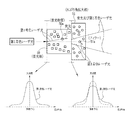
特許文献1のように、青色LED及び蛍光体を用いて白色光を生成した場合には、小型化と省電力化を図ることができる一方、蛍光体の光拡散特性は波長依存性を有しているため、蛍光体から出射する励起光である青色光の広がり角と、その青色光により励起される蛍光の広がり角との間に差が生じることがある。例えば、中心波長405nmの青色レーザ光と中心波長445nmの青色レーザ光で蛍光体から蛍光を発光させた場合には、図11に示すように、蛍光の広がり角が一番広く、中心波長405nmの青色レーザ光及び中心波長445nmの青色レーザ光の広がり角は蛍光よりも狭くなっている。このように広がり角に差がある状態で青色光及び蛍光を被検体に照射した場合には、被検体上で色むらが生じてしまう。色むらが生じた状態で撮像した画像では、正確な診断を行うことができないことがある。 When white light is generated using a blue LED and a phosphor as in Patent Document 1, it is possible to reduce the size and power consumption, while the light diffusion characteristics of the phosphor have wavelength dependence. Therefore, there may be a difference between the divergence angle of blue light that is excitation light emitted from the phosphor and the divergence angle of fluorescence excited by the blue light. For example, when fluorescence is emitted from a phosphor with a blue laser beam having a central wavelength of 405 nm and a blue laser beam having a central wavelength of 445 nm, as shown in FIG. 11, the fluorescence spread angle is the widest and the central wavelength is 405 nm. The spread angle of the blue laser light and the blue laser light having a center wavelength of 445 nm is narrower than that of fluorescence. When the subject is irradiated with blue light and fluorescence in a state where there is a difference in the spread angle in this way, color unevenness occurs on the subject. Accurate diagnosis may not be performed on an image captured in a state where color unevenness has occurred.
色むらの発生を防ぐ方法の一つとして、直進的に出射する青色光を散乱させるフィラーを蛍光体に混入させることが考えられる(例えば、特許文献2参照)。しかしながら、一般的には、蛍光体へのフィラーの混入は、励起光である青色光を拡散する機能と、その青色光により蛍光体で励起される蛍光を放射する機能とを分離しにくくなるため、完全に色むらを無くすことは困難である。また、フィラーは、青色光を四方八方に散乱させるため、蛍光体内だけで散乱し、蛍光体から出射しない青色光が増えることになる。このような青色光の増加は、蛍光体での発光効率を低下させる要因となるとともに、蛍光体内部や蛍光体の出射端が発熱する要因となる。 As one method for preventing the occurrence of uneven color, it is conceivable to add a filler that scatters the blue light emitted in a straight line to the phosphor (for example, see Patent Document 2). However, generally, mixing of the filler into the phosphor makes it difficult to separate the function of diffusing the blue light that is the excitation light from the function of emitting the fluorescence excited by the phosphor by the blue light. It is difficult to completely eliminate uneven color. Further, since the filler scatters blue light in all directions, the blue light that scatters only in the phosphor and does not exit the phosphor increases. Such an increase in blue light causes a decrease in luminous efficiency of the phosphor, and also causes a heat generation inside the phosphor and the emission end of the phosphor.
また、一般的には、蛍光体の長期安定性を確保するために、蛍光体とその蛍光体からの青色光及び蛍光を被検体に向けて出射する照明窓とを密封しているが、密封時には、蛍光体と照射窓との間に若干の隙間(空気層ともいう)が形成される。この空気層があることで、一部の青色光や蛍光は、照明窓の出射面から出射せず、照明窓の入射面で反射したり、また蛍光体の出射面で反射することがある。このような照明窓や蛍光体での反射は、蛍光の発光効率を低下させる要因となってしまう。 In general, in order to ensure long-term stability of the phosphor, the phosphor and the illumination window that emits blue light and fluorescence from the phosphor toward the subject are sealed. Sometimes, a slight gap (also referred to as an air layer) is formed between the phosphor and the irradiation window. Due to the presence of this air layer, some blue light and fluorescence may not be emitted from the exit surface of the illumination window, but may be reflected from the entrance surface of the illumination window or reflected from the exit surface of the phosphor. Such reflection on the illumination window or the phosphor causes a reduction in fluorescence emission efficiency.
この問題に対して、照明窓の入射面には反射防止膜(ARコート)を導入することで、照明窓の入射面での反射を防ぐことができる。しかしながら、蛍光体は製造工程上、出射面の平面性を確保することができないため、照明窓のような反射防止膜を導入することができない。そのため、蛍光体においては反射防止膜を使わずに、青色光や蛍光の反射を防ぐことが必要となる。 With respect to this problem, by introducing an antireflection film (AR coating) on the incident surface of the illumination window, reflection on the incident surface of the illumination window can be prevented. However, since the phosphor cannot ensure the flatness of the emission surface in the manufacturing process, an antireflection film such as an illumination window cannot be introduced. Therefore, it is necessary to prevent reflection of blue light or fluorescence without using an antireflection film in the phosphor.
本発明は、青色光とこの青色光で蛍光体から励起発光させた蛍光とを合波した白色光を被検体に照射する際に、異なる波長の青色光及び蛍光を被検体に照射することによる色むらの発生を防ぐとともに、蛍光体での蛍光の発光効率の低下を抑制することができる内視鏡用投光ユニットを提供することを目的とする。 The present invention is directed to irradiating a subject with blue light and fluorescence having different wavelengths when irradiating the subject with white light obtained by combining blue light and fluorescence excited and emitted from the phosphor with the blue light. An object of the present invention is to provide an endoscopic light projecting unit that can prevent the occurrence of color unevenness and suppress a decrease in the light emission efficiency of fluorescence in a phosphor.
上記目的を達成するために、本発明は、内視鏡の先端部に設けられ、被検体に向けて照明光を照射する内視鏡用投光ユニットにおいて、所定波長の光の一部を吸収して波長変換することにより蛍光を生成し、残りの光を透過することにより、前記所定波長の光と前記蛍光を含む照明光を出射する波長変換部材と、前記波長変換部材を出射した照明光を透明な基材中に混入した散乱部材で散乱させて前記照明光の広がり角を拡大する広がり角拡大部と、前記被検体に向けて前記散乱させた照明光を照射する照明窓とを備え、前記波長変換部材と前記広がり角拡大部、及び、前記広がり角拡大部と前記照明窓は別体で密着して構成され、前記広がり角拡大部の前記基材の屈折率は、前記波長変換部材の屈折率と前記照明窓の屈折率の間の値であり、前記波長変換部材及び前記広がり角拡大部は略円柱形状を有しており、前記広がり角拡大部の径は前記波長変換部材の径よりも大きいことを特徴とする。 In order to achieve the above object, the present invention absorbs a part of light having a predetermined wavelength in an endoscope projection unit that is provided at the distal end portion of an endoscope and irradiates illumination light toward a subject. The wavelength conversion member generates the fluorescence by converting the wavelength and transmits the remaining light, thereby emitting the light of the predetermined wavelength and the illumination light including the fluorescence, and the illumination light emitted from the wavelength conversion member Are spread by a scattering member mixed in a transparent substrate to widen the spread angle of the illumination light, and an illumination window that irradiates the scattered illumination light toward the subject The wavelength conversion member and the divergence angle widening portion, and the divergence angle widening portion and the illumination window are configured to be in close contact with each other, and the refractive index of the base material of the divergence angle widening portion is the wavelength conversion. Ri value der between the refractive index and the refractive index of the illumination window of the member The wavelength conversion member and the divergence angle increasing unit has a substantially cylindrical shape, the diameter of the spread angle increasing unit may be greater than the diameter of the wavelength conversion member.
前記波長変換部材には前記散乱部材は混入されていないことが好ましい。 The scattering member before Symbol wavelength conversion member is preferably not mixed.
前記波長変換部材の屈折率は、1.46〜2.0の範囲内であり、前記照明窓の屈折率は、1.40〜1.9の範囲内であり、前記基材の屈折率は、前記波長変換部材及び前記照明窓のそれぞれの屈折率の値の組み合わせに応じて、1.40〜2.0の範囲の中から選択されることが好ましい。前記基材の屈折率は、前記波長変換部材の屈折率と前記照明窓の屈折率の二乗平均値であることが好ましい。 The refractive index of the wavelength conversion member is in the range of 1.46 to 2.0, the refractive index of the illumination window is in the range of 1.40 to 1.9, and the refractive index of the substrate is The wavelength conversion member and the illumination window are preferably selected from the range of 1.40 to 2.0 depending on the combination of the refractive index values of the illumination window and the wavelength conversion member. The refractive index of the base material is preferably a mean square value of the refractive index of the wavelength conversion member and the refractive index of the illumination window.
前記基材は、例えばエポキシなどの有機材料であることが好ましい。前記基材は、無機材料であることが好ましい。 The substrate is preferably an organic material such as epoxy. The substrate is preferably a inorganic materials.
前記波長変換部材を保持するフェルールと、前記広がり角拡大部とを保持する金属製のスリーブを備えることが好ましい。 It is preferable to provide a metal sleeve that holds the ferrule that holds the wavelength conversion member and the divergence angle widening portion .
本発明によれば、波長変換部材を出射した後の照明光を散乱させることによって、照明光の広がり角を拡大しているので、波長変換部材内で照明光を散乱させた場合と比較して、照明光の色むらの発生をより確実に防止することができるとともに、波長変換部材での発光効率の低下を更に抑制することができる。 According to the present invention, the divergence angle of the illumination light is expanded by scattering the illumination light after exiting the wavelength conversion member, so compared with the case where the illumination light is scattered within the wavelength conversion member. Further, it is possible to more reliably prevent the uneven color of the illumination light and to further suppress the decrease in the light emission efficiency at the wavelength conversion member.
また、広がり角拡大部と照明窓とを別体で構成した場合には、広がり角拡大部に、波長変換部材の屈折率と照明窓の屈折率の間の中間屈折率を有する基材を含有させることで、照明光は波長変換部材の出射面や照明窓の入射面などでの反射が防止される。これにより、波長変換部材や照明窓での照明光の損失を抑えることができる。また、波長変換部材と広がり角拡大部を密着させるとともに、広がり角拡大部と照明窓とも密着させることで、波長変換部材の出射面など各境界面での反射が防止される。これによっても、照明光の損失を抑えることができる。 Further, when the divergence angle widening portion and the illumination window are configured separately, the divergence angle widening portion includes a base material having an intermediate refractive index between the refractive index of the wavelength conversion member and the refractive index of the illumination window. By doing so, the illumination light is prevented from reflecting on the exit surface of the wavelength conversion member, the entrance surface of the illumination window, and the like. Thereby, the loss of the illumination light in a wavelength conversion member or an illumination window can be suppressed. In addition, the wavelength conversion member and the divergence angle widening portion are brought into close contact with each other, and the divergence angle widening portion and the illumination window are brought into close contact with each other, thereby preventing reflection at each boundary surface such as the emission surface of the wavelength conversion member. Also by this, the loss of illumination light can be suppressed.
また、広がり角拡大部と照明窓とを一体で構成した場合には、波長変換部材と照明窓を密着させることで、照明光は波長変換部材の出射面や照明窓の入射面などでの反射が防止される。これにより、照明光の損失を抑えることができる。 When the divergence angle widening part and the illumination window are integrated, the wavelength conversion member and the illumination window are brought into close contact so that the illumination light is reflected on the exit surface of the wavelength conversion member or the entrance surface of the illumination window. Is prevented. Thereby, the loss of illumination light can be suppressed.
また、広がり角拡大部は金属製のスリーブで保持されていることから、そのスリーブに、広がり角拡大部内での照明光の散乱による発熱を逃がすことができる。また、広がり角拡大部の径を波長変換部材の径よりも大きくすることで、波長変換部材で生じた発熱を外部に逃がす効果を高めることができる。 In addition, since the divergence angle widening portion is held by a metal sleeve, heat generated by scattering of illumination light in the divergence angle widening portion can be released to the sleeve. Moreover, the effect of releasing the heat generated by the wavelength conversion member to the outside can be enhanced by making the diameter of the divergence angle widening portion larger than the diameter of the wavelength conversion member.
図1に示すように、第1実施形態の内視鏡システム2は、被検体を撮影する電子内視鏡10と、内視鏡画像を生成するプロセッサ装置12と、このプロセッサ装置12内に設けられ、被検体を照明する照明光を供給する光源装置13と、内視鏡画像を表示するモニタ14と、被検体内に送り込む水を貯留する送水タンク16とを備えている。
As shown in FIG. 1, the
電子内視鏡10は、患者の体腔内に挿入される挿入部20と、挿入部20の基端部分に連設され、医師や技師などの術者が手元で操作を行なう操作部22と、操作部22から延びるユニバーサルコード24とからなる。挿入部20は、先端から順に、先端部26、湾曲部27、及び可撓管部28で構成されている。先端部26は、硬質な樹脂材料で形成されている。可撓管部28は、細径かつ長尺な管状に形成されるとともに、可撓性を有しており、操作部22と湾曲部27とを接続する。
The electronic endoscope 10 includes an
湾曲部27は、操作部22に設けられた上下用操作ノブ30及び左右用操作ノブ31の回転操作に応じて上下左右に湾曲するように構成されている。上下用操作ノブ30を回転操作すると、湾曲部27が上下方向に湾曲し、左右用操作ノブ31を回転操作すると、湾曲部27が左右方向に湾曲する。
The bending
ユニバーサルコード24には、プロセッサ装置12から供給される光及び空気の取り込みと、電源や各種の制御信号の伝送に用いられるコネクタ36とが設けられている。電子内視鏡10は、コネクタ36を介してプロセッサ装置12に着脱自在に接続される。
The
光源装置13は、中心波長445nmの第1青色レーザ光を発する第1レーザ光源13aを備えている。第1レーザ光源13aから発せられる第1青色レーザ光は、ユニバーサルコード24内のライドガイド24a,24bを介して、電子内視鏡の先端部26まで導光される。導光された第1青色レーザ光は、一部が先端部26に設けられた蛍光体50で吸収されることにより緑色〜黄色の蛍光を励起発光させるとともに、蛍光体50(波長変換部材)で吸収されなかった光はそのまま蛍光体50を透過する。これにより、先端部26からは、第1青色レーザ光と蛍光が合波した白色光(照明光)が被検体に照射される。被検体からの戻り光は、被検体の像として電子内視鏡10内の撮像素子42(図3参照)により撮像される。なお、ライトガイド24a,24bは、光ファイバなどの導光部材で構成される。
The light source device 13 includes a first laser light source 13a that emits a first blue laser beam having a center wavelength of 445 nm. The first blue laser light emitted from the first laser light source 13 a is guided to the
プロセッサ装置12は、電子内視鏡10の撮像により得られる撮像信号を、ユニバーサルコード24内の信号ケーブル24cを介して受信する。プロセッサ装置12では、受信した撮像信号に各種画像処理を施すことによって、画像データを生成する。この生成された画像データに基づいて、モニタ14に被検体の内視鏡画像が表示される。
The
図2に示すように、電子内視鏡の先端部26には、被検体に向けて照明光を照射するための2灯の第1及び第2投光ユニット38,39と、観察窓40及び撮像レンズ41を介して受光した被検体の像を、CCDなどの撮像素子42で撮像する撮像ユニット43が設けられている。
As shown in FIG. 2, at the
図3に示すように、第1及び第2投光ユニット38,39は、先端部26の先端面26aにおいて、撮像ユニット43に関して左右対称の位置に設けられている。なお、先端部26には、第1及び第2投光ユニット38,39、撮像ユニット43の他、スネアなどの処置具を露呈させる処置具出口46や観察窓40に向けて洗浄用の空気や水を吐出する送気送水ノズル48が設けられている。
As shown in FIG. 3, the first and second
第1投光ユニットは、ライトガイド24aからの第1青色レーザ光で蛍光体50を励起させて蛍光体50から白色光を発するとともに、発せられた白色光の広がり角を広がり角拡大部51で拡げる。広がり角拡大部51を経た白色光は、石英ガラスやサファイヤガラスなどのガラス部材のうち生体適合性を有するもの(例えば「K-LaSFn17」(「http://www.sumita-opt.co.jp/data/glassdata.pdf」の120ページ参照))で形成された照明窓52を介して、被検体に照射される。なお、蛍光体はYAGやBAM(BaMgAl10O17)であることが好ましい。
The first light projecting unit excites the
この第1及び第2投光ユニット38,39においては、照明窓52と広がり角拡大部51との間、及び広がり角拡大部51と蛍光体50との間は、それぞれ隙間無く接触している(密着している)ため、それらの間に空気層は存在しない。ここで、照明窓52と広がり角拡大部51との間、及び広がり角拡大部51と蛍光体50との間に空気層を挟んだ場合は、空気層を挟まない場合と比べて、光入射・反射面などの境界面の数を減らすことができる(空気層を挟んだ場合は境界面の数が「5」であるのに対し、空気層を挟まない場合は境界面の数が「3」となる)。そのため、各部材間を密着させて空気層を無くすことにより、境界面の数を減らすことができる。これにより、境界面での反射を防止することができるため、高い光強度を保持した状態で、第1青色レーザ光及び蛍光を被検体に照射することができる。
In the first and second
蛍光体50は、一定の外径D1を持つ略円柱形状を有している。この蛍光体50には蛍光物質が混入されており、第1青色レーザ光のうち、一部がその蛍光物質に吸収されて緑色〜赤色の蛍光を発する一方、蛍光物質に吸収されなかった光は蛍光体50をそのまま透過する。このように蛍光物質から発せられた蛍光と第1青色レーザ光とが合波されて、蛍光体50から白色光が発せられる。
The
広がり角拡大部51は、透明材料からなる基材51b(図4参照)に、蛍光及び第1青色レーザ光を散乱させる光散乱部材であるフィラー51aを混入させて形成した透光性部材である。基材51bとしては、例えば、樹脂などの有機材料が使用され、その屈折率が、蛍光体50の屈折率と照明窓52の屈折率の間の材料が使用される。
The divergence
この広がり角拡大部51は略円柱形状をしており、その外径D2は蛍光体50の外径D1よりも大きくなっている。そのため、蛍光体50から出射した光のうち、広がり角拡大部51に入射しない漏れ光が減るので、光損失を低減できる。また、蛍光体50の出射面全体が広がり角拡大部51と接触しているため、蛍光体50での発熱が広がり角拡大部51に伝達される。なお、蛍光体50の外径D1は例えば0.8mmであり、広がり角拡大部51の外径D2は例えば1.1mmであることが好ましい。
The divergence
図4に示すように、蛍光体50に入射する第1青色レーザ光は、光強度が大きい部分の広がり角は比較的狭くなっている。これに伴って、第1青色レーザ光によって蛍光体50で励起される蛍光の広がり角も狭くなる。そこで、蛍光体50から出射した第1青色レーザ光及び蛍光をフィラー51aで散乱させることによって、それぞれの光の広がり角を拡げる。このように第1青色レーザ光及び蛍光の両方の広がり角を拡げることで、それぞれの光が重なり合わない部分が無くなるため、色むらの発生を防止できる。
As shown in FIG. 4, the first blue laser light incident on the
なお、フィラーとしては、シリカ、石英などが好ましいが、光拡散機能を有するものであればこれに限定されない。また、有機材料としてはエポキシなどの樹脂であることが好ましいが、短波長の第1青色レーザ光の照射による劣化を考慮する場合には、有機材料に代えて、シリコンなどの無機材料を使用してもよい。 In addition, as a filler, although silica, quartz, etc. are preferable, if it has a light-diffusion function, it will not be limited to this. In addition, the organic material is preferably a resin such as epoxy. However, when considering deterioration due to irradiation with the first blue laser light having a short wavelength, an inorganic material such as silicon is used instead of the organic material. May be.
蛍光体50には、広がり角拡大部51が含有するフィラー51aは混入されていない。このように、フィラー51aを、蛍光体50に混入させるのではなく、蛍光体50とは別体の広がり角拡大部51に混入することによって、励起光である第1青色レーザ光を拡散する励起光拡散機能と、その第1青色レーザ光により蛍光体50で励起される蛍光を放射する蛍光放射機能とを分離することができる。したがって、以下示すような理由から、フィラー51aを蛍光体50に混入させる場合(励起光拡散機能と蛍光放射機能を一体化した場合)と比較して、色むらを防止できる効果と、発光効率の低下を抑制できる効果とを確実に得ることができる。
In the
色むらの防止効果については、励起光拡散機能と蛍光放射機能を一体化した場合と分離した場合とで、以下のような違いがある。両機能を一体化した場合には、図5Aに示すように、蛍光体50内のフィラー51aによって拡散された第1青色レーザ光は、一部が蛍光体50から出射するものの、その他は蛍光体50内の蛍光物質50aで吸収されて蛍光の励起発光に消費される。これにより、第1青色レーザ光の拡散効果が小さくなるため、フィラー51aによる広がり角拡大効果は低下する。そして、この広がり角拡大効果の低下によって、色むら防止効果が小さくなる。
Regarding the effect of preventing color unevenness, there are the following differences between the case where the excitation light diffusion function and the fluorescence emission function are integrated and the case where they are separated. When both functions are integrated, as shown in FIG. 5A, a part of the first blue laser light diffused by the
これに対して、図5Bに示すように、励起光拡散機能と蛍光放射機能を分離した場合には、蛍光体50を出射した後の第1青色レーザ光に対して、フィラー51aで拡散効果が付与される。この拡散効果が付与された第1青色レーザ光は、照明窓52を通してそのまま被検体に向けて照射されるため、上記のように、蛍光の励起発光に使用されることはない。そのため、フィラー51aによる拡散効果は、ほぼ100%広がり角拡大に使用される。したがって、励起光拡散機能と蛍光放射機能を一体化した場合と比べて、確実に色むら防止効果を得ることができる。
On the other hand, as shown in FIG. 5B, when the excitation light diffusion function and the fluorescence emission function are separated, the
また、発光効率の低下抑制効果については、励起光拡散機能と蛍光放射機能を一体化した場合と分離した場合とで、以下のような違いがある。両機能を一体化した場合には、図6Aに示すように、蛍光体50の蛍光物質50aに照射される光には、フィラー51aに衝突せずにそのまま蛍光物質50aに照射される第1青色レーザ光だけでなく、フィラー51aに衝突して散乱する第1青色レーザ光も含まれる。フィラー51aに衝突した第1青色レーザ光は、衝突によってエネルギーが減衰するため、その一部は、蛍光物質50aに照射されても蛍光の励起発光には寄与せず、かつ、蛍光体50からも出射しない損失光となる場合がある。損失光のエネルギーは熱に変換されて蛍光体50内で消失する。損失光が多いと、発光効率が低下するとともに、蛍光体50の発熱も大きくなる。
Further, regarding the effect of suppressing the decrease in luminous efficiency, there are the following differences between the case where the excitation light diffusion function and the fluorescence emission function are integrated and the case where they are separated. When both functions are integrated, as shown in FIG. 6A, the light emitted to the
これに対して、図6Bに示すように、励起光拡散機能と蛍光放射機能を分離した場合には、蛍光体50にはフィラー51aが入っていないため、蛍光体50に進入した第1青色レーザ光において、フィラー51aによるエネルギーの減衰はない。したがって、第1青色レーザ光は、比較的高いエネルギーを保持した状態で蛍光体50の蛍光物質50aに照射されるため、蛍光の励起光率を向上させることができる。また、蛍光物質に50aに吸収されなかった第1青色レーザ光は、比較的高いエネルギーを保持しているため、ほとんどが蛍光体50から出射する。そのため、蛍光体50内において発熱のみ消費される損失光が低減される。
On the other hand, as shown in FIG. 6B, when the excitation light diffusing function and the fluorescence emission function are separated, since the
また、蛍光体50を出射した後の第1青色レーザ光は、蛍光体50を通過することで、若干広がり角が拡大している。このように、蛍光体50自体にも広がり角拡大作用があるため、広がり角拡大部51におけるフィラー51aの混入率を、蛍光体50の広がり角拡大効果を差し引いて設定することができる。すなわち、第1青色レーザ光を、蛍光体50に直接入射させる場合と比較して、広がり角拡大部51におけるフィラー51aの混入率を下げることができる。混入率を下げた分だけ、広がり角拡大部51による広がり角拡大効果は減少するが、その減少分は、蛍光体50の広がり角拡大効果によって補償される。以上から、励起光拡散機能と蛍光放射機能を分離した場合は、それら両機能を一体化した場合と比べて、発光効率や発熱抑制効果を高めることができる。
Further, the first blue laser light after being emitted from the
なお、励起光拡散機能と蛍光放射機能を分離した場合には、蛍光の発光効率と第1青色レーザ光の散乱効率とを分けて考えることができるため、蛍光体50における蛍光物質の混入率と、広がり角拡大部51におけるフィラー51aの混入率の設計がしやすい。というのは、蛍光体内にフィラーを混入させる場合には、蛍光体内における蛍光物質とフィラーの相互作用を考慮してそれぞれの混入率を決定しなければならないが、分離していれば、それぞれの混入率を独立に調整できるので、双方の混入率の最適な組み合わせの選択もしやすい。
When the excitation light diffusion function and the fluorescence emission function are separated, the fluorescence emission efficiency and the first blue laser light scattering efficiency can be considered separately. In addition, it is easy to design the mixing rate of the
また、蛍光体50に対して、別体で構成される広がり角拡大部51を追加して、かつ、両者を密着させることで、蛍光体50単体の場合と比較して、広がり角拡大部51が追加された分、熱容量及び表面積が大きくなる。そのため、蛍光体50の発熱を広がり角拡大部51に逃がすことができるようになるため、放熱効果も向上する。
In addition, the divergence
また、蛍光体50とは別体の広がり角拡大部51にフィラー51aを設けていることで、このフィラー51aにより散乱する第1青色レーザ光は、大部分が照明窓52側に向かうものの、一部は蛍光体50に向かう戻り光となる。この戻り光は、蛍光体50に再入射して、再び蛍光の励起発光に使用される。これにより、蛍光の発光量を増加させることができるため、戻り光は有効的に利用される。これに対して、蛍光体50内にフィラー51aを設けた場合には、フィラー51aによって、第1青色レーザ光が照明窓52とは反対側(フェルール55側)に散乱すると、その散乱光の多くは、蛍光体50から出射して損失となってしまう。この場合には、散乱光は、上記戻り光のように、蛍光の励起発光に使用されることないため、有効的に利用されない。
In addition, since the
また、第1青色レーザ光は、蛍光体50、広がり角拡大部51、照明窓52、空気層の順に、蛍光は、広がり角拡大部51、照明窓52、空気層の順に、各媒質を透過する。上述したとおり、光を透過する媒質間の屈折率の差は小さいほど反射が少ないので、反射による光損失を減らすためには、屈折率が最小の空気層(屈折率:1.0)と接する照明窓52の屈折率nyを1.0に近づくように最も小さくし、かつ、蛍光体50の屈折率nx、広がり角拡大部51の屈折率nk、照明窓52の屈折率nyの順に、各媒質の屈折率を段階的に小さくしていくのが好ましい。そのため、広がり角拡大部51の基材51bの屈折率nkは、蛍光体50の屈折率nxと照明窓52の屈折率nyの中間の値に設定され、かつ、蛍光体50、広がり角拡大部51、照明窓52の順に各媒質の屈折率が小さくなるように(nx>nk>ny)、それぞれの材料が選択されている。これにより、第1青色レーザ光及び蛍光の光損失が低減されるので、被検体に照射される照明光は高い光強度が確保される。
The first blue laser light passes through each medium in the order of the
広がり角拡大部51の基材51bの屈折率nkの値は、1.40〜2.0の範囲(中間屈折率の範囲)であることが好ましい。一般的に使用される蛍光体50の材料の屈折率nxは、1.46〜2.0程度であり、照明窓52の屈折率nyは、1.40〜1.9程度であり、中間屈折率の範囲は、蛍光体50の屈折率nxの最大値と、照明窓52の屈折率nyの最小値によって規定したものである。広がり角拡大部51の基材51bの屈折率nkの値は、製品に使用する蛍光体50の屈折率nx及び照明窓52の屈折率nyのそれぞれの値の組み合わせに応じて、その中間の値となるように、上記中間屈折率の範囲の中から適宜選択される。なお、基材51bの材料として、無機材料を用いた場合であっても、無機材料の好ましい屈折率の範囲は上記の有機材料の場合と同じである。
The value of the refractive index nk of the
また、基材51bの屈折率nkは、蛍光体の屈折率nxと照明窓の屈折率nyの二乗平均値(nk=(0.5×(nx2+ny2))1/2)であることが好ましい。例えば、nxが1.46であり、nyが1.4である場合にはnkは1.43である。また、nyについては1.3〜1.4の間の値であることが好ましい。
Further, the refractive index nk of the
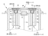
第1投光ユニット38では、ライトガイド24a、蛍光体50、広がり角拡大部51、及び照明窓52は、以下のように配置される。蛍光体50とライトガイド24aは、互いに光学的に接続された状態でフェルール55によって保持される。フェルール55は中空の円筒部材であり、軸方向に延びた貫通孔55aでライトガイド24aを保持する。また、フェルール55は、先端側に開口部を有する略円柱状または直方体状の先端収納部55b内で、蛍光体50を接着剤56によって固定している。
In the 1st
また、フェルール55と照明窓52は金属製のスリーブ60により保持され、この金属製のスリーブ60においてフェルール55と照明窓52の間に広がり角拡大部51が設けられる。広がり角拡大部51では、第1青色レーザ光及び蛍光をフィラー51aで散乱させているため発熱が生ずるが、広がり角拡大部51は金属製のスリーブ60に直接的に接しているため、その発熱をスリーブ60に逃がすことができる。これにより、放熱効果を高めることができる。
Further, the
なお、第1投光ユニット38は以下のような方法により製造することが好ましい。まず、図7に示すように、照明窓52をスリーブ60の照明窓設置部60aに対して取り付けた上で、照明窓設置部60aの一部に形成される空間に、基材51bにフィラー51aを混入した有機材料を充填して、広がり角拡大部51を形成する。次に、先端収納部55bに蛍光体50を固定させたフェルール55を、スリーブ60のフェルール挿入孔60bに挿入する。フェルール55に固定された蛍光体50が広がり角拡大部51と当接する位置まで挿入されたら、有機材料及びフィラーを硬化させる処理を行う。この処理の完了により、照明窓52と蛍光体50の間に広がり角拡大部51が形成された第1投光ユニット38が完成する。この製造後の第1投光ユニット38においては、照明窓52と広がり角拡大部51との間、及び広がり角拡大部51と蛍光体50と間は、それぞれ隙間無く接触している密着した状態となっている。
The first
第2投光ユニット39は、第1投光ユニット38と同様の蛍光体50、広がり角拡大部51、照明窓52、フェルール55、及びスリーブ60を備えている。また、第2投光ユニット39の各部材の配置及び製造方法は第1投光ユニット38と同様である。そのため、詳細な説明は省略する。
The second
図8に示すように、第2実施形態の第1及び第2投光ユニット100,101は、照明窓52に広がり角拡大機能を設けて、照明窓52と広がり角拡大部を一体にした例である。照明窓52は、照明窓52を形成するための透明材料を基材として、その基材中にフィラー52aを混入することで形成される。照明窓52と蛍光体50との間は密着される。それ以外については、第1実施形態と同様に実施する。ここで、密着とは、蛍光体50と照明窓52との間が隙間無く接触することをいう。なお、第2実施形態の第1及び第2投光ユニット100,101においても、放熱効果等の観点から、略円柱形状の照明窓52の外径D3は、蛍光体50の外径D1よりも大きくすることが好ましい。
As shown in FIG. 8, the 1st and 2nd light projection unit 100,101 of 2nd Embodiment provided the divergence angle expansion function in the
第1及び第2投光ユニット100,101のように、照明窓52にフィラー52aを混入した場合にも、蛍光体50からの第1青色レーザ光及び蛍光はフィラー52aで散乱するため、それぞれの光の広がり角を確実に拡げることができる。また、第1及び第2投光ユニット100,101においても、上記第1実施形態と同様に、フィラー51aを、蛍光体50に混入させるのではなく、蛍光体50とは別体の照明窓52に混入することによって、励起光拡散機能と蛍光放射機能とを分離することができる。この場合は、励起光拡散機能と蛍光放射機能を一体化した場合と比較して、色むら防止効果、発光効率の低下抑制効果、発熱抑制効果など上記第1実施形態と同様の効果を確実に得ることができる。
Even when the
また、照明窓52は金属製のスリーブ60と直接的に接触しているため、フィラー52aによる第1青色レーザ光及び蛍光の散乱で発熱が生じたとしても、その熱をスリーブ60に逃がすことができる。
Further, since the
また、第2実施形態の第1及び第2投光ユニット100,101では、蛍光体50と照明窓52とは密着しているため、それらの間に空気層はほとんど存在しない。そのため、第1青色レーザ光及び蛍光が蛍光体50の出射面で反射したり、また照明窓52の入射面で反射することが防止される。したがって、第1青色レーザ光及び蛍光は、蛍光体50や照明窓52で減衰することなく、ほぼ全てが被検体に照射される。
Moreover, in the 1st and 2nd light projection unit 100,101 of 2nd Embodiment, since the
なお、第2実施形態の第1及び第2投光ユニット100,101は、蛍光体50と照明窓52とを密着させるため、第1実施形態とは異なる方法で製造される。まず、図9に示すように、フィラー52aを混入させた照明窓52を、スリーブ60の照明窓設置部60aに取り付ける。次に、先端収納部55bに蛍光体を固定させたフェルール55を、スリーブ60のフェルール挿入孔60bに挿入する。その際、蛍光体50と照明窓52とが完全に接触するまで挿入する。ここで、接触とは、蛍光体50と照明窓52との間が隙間無く接触すること、すなわち密着することをいう。次に、スリーブ60をアニール装置110に入れ、アニール処理を行う。このアニール処理の完了により、蛍光体50と照明窓52とが密着した第1及び第2投光ユニット100,101が完成する。なお、アニール処理は、70〜90℃、10〜30Hの範囲内の所定条件下、例えば80℃、20Hの条件下で行うことが好ましい。
The first and second light projecting units 100 and 101 of the second embodiment are manufactured by a method different from that of the first embodiment in order to bring the
なお、上記第1及び第2実施形態では、中心波長445nmの第1青色レーザ光のみで蛍光体を励起したが、この第1青色レーザ光に加えて、中心波長405nmの第2青色レーザ光で蛍光体を励起してもよい。その際、第2青色レーザ光は、第1青色レーザ光とともに蛍光体50に入射させる。
In the first and second embodiments, the phosphor is excited only by the first blue laser beam having the center wavelength of 445 nm. In addition to the first blue laser beam, the second blue laser beam having the center wavelength of 405 nm is used. The phosphor may be excited. At that time, the second blue laser light is incident on the
このように第1及び第2青色レーザ光の2波長の光で蛍光体を励起する場合にも、図10に示すように、蛍光体50の入射時点では、第1及び第2青色レーザ光の広がり角及びそれら光で蛍光体50から励起される蛍光の広がり角も狭くなっているが、蛍光体50の出射後には、広がり角拡大部51でそれぞれ光の広がり角は拡げられるため、色むらが生じることはない。また、蛍光体50を励起する光を1種類追加したことで、広がり角拡大部51で散乱する光の量も多くなり発熱量が増加するが、その発熱は金属製のスリーブ60に十分に逃がすことができるため、放熱効果が落ちることは無い。
Even when the phosphor is excited by the two wavelengths of the first and second blue laser beams in this way, as shown in FIG. 10, at the time of incidence of the
また、図10の場合においても、上記第1実施形態と同様に、フィラー51aを、蛍光体50に混入させるのではなく、蛍光体50とは別体の広がり角拡大部51に混入することによって、励起光拡散機能と蛍光放射機能とを分離することができる。そのため、励起光拡散機能と蛍光放射機能を一体化した場合と比較して、色むら防止効果、発光効率の低下抑制効果、発熱抑制効果など上記第1実施形態と同様の効果を確実に得ることができる。
Also in the case of FIG. 10, as in the first embodiment, the
38,39 第1及び第2投光ユニット
50 蛍光体
51 広がり角拡大部
51a,52a フィラー
52 照明窓
55 フェルール
60 スリーブ
38, 39 1st and 2nd
Claims (8)
所定波長の光の一部を吸収して波長変換することにより蛍光を生成し、残りの光を透過することにより、前記所定波長の光と前記蛍光を含む照明光を出射する波長変換部材と、
前記波長変換部材を出射した照明光を透明な基材中に混入した散乱部材で散乱させて前記照明光の広がり角を拡大する広がり角拡大部と、
前記被検体に向けて前記散乱させた照明光を照射する照明窓とを備え、
前記波長変換部材と前記広がり角拡大部、及び、前記広がり角拡大部と前記照明窓は別体で密着して構成され、前記広がり角拡大部の前記基材の屈折率は、前記波長変換部材の屈折率と前記照明窓の屈折率の間の値であり、
前記波長変換部材及び前記広がり角拡大部は略円柱形状を有しており、前記広がり角拡大部の径は前記波長変換部材の径よりも大きいことを特徴とする内視鏡用投光ユニット。 In the endoscope projecting unit that is provided at the distal end of the endoscope and irradiates illumination light toward the subject,
A wavelength conversion member that absorbs a part of light of a predetermined wavelength and generates fluorescence by converting the wavelength, and transmits the remaining light, thereby emitting illumination light including the light of the predetermined wavelength and the fluorescence,
A divergence angle widening part that scatters the illumination light emitted from the wavelength conversion member with a scattering member mixed in a transparent base material to widen the spread angle of the illumination light; and
An illumination window for irradiating the scattered illumination light toward the subject,
The wavelength conversion member and the divergence angle widening portion, and the divergence angle widening portion and the illumination window are configured to be in close contact with each other, and the refractive index of the base material of the divergence angle widening portion is the wavelength conversion member. value der between the refractive index of the illumination window and the refractive index of the is,
The endoscope light projecting unit, wherein the wavelength conversion member and the divergence angle widening portion have a substantially cylindrical shape, and a diameter of the divergence angle widening portion is larger than a diameter of the wavelength conversion member .
Priority Applications (2)
| Application Number | Priority Date | Filing Date | Title |
|---|---|---|---|
| JP2012071445A JP5480929B2 (en) | 2011-04-21 | 2012-03-27 | Endoscopic light projecting unit |
| CN201210118694XA CN102743145A (en) | 2011-04-21 | 2012-04-20 | Light projection unit used for endoscope |
Applications Claiming Priority (3)
| Application Number | Priority Date | Filing Date | Title |
|---|---|---|---|
| JP2011095019 | 2011-04-21 | ||
| JP2011095019 | 2011-04-21 | ||
| JP2012071445A JP5480929B2 (en) | 2011-04-21 | 2012-03-27 | Endoscopic light projecting unit |
Publications (2)
| Publication Number | Publication Date |
|---|---|
| JP2012232108A JP2012232108A (en) | 2012-11-29 |
| JP5480929B2 true JP5480929B2 (en) | 2014-04-23 |
Family
ID=47433072
Family Applications (1)
| Application Number | Title | Priority Date | Filing Date |
|---|---|---|---|
| JP2012071445A Expired - Fee Related JP5480929B2 (en) | 2011-04-21 | 2012-03-27 | Endoscopic light projecting unit |
Country Status (1)
| Country | Link |
|---|---|
| JP (1) | JP5480929B2 (en) |
Families Citing this family (2)
| Publication number | Priority date | Publication date | Assignee | Title |
|---|---|---|---|---|
| DE112015006369T5 (en) * | 2015-04-23 | 2017-12-14 | Olympus Corporation | Lighting device, endoscope and endoscope system |
| WO2021039221A1 (en) | 2019-08-27 | 2021-03-04 | 富士フイルム株式会社 | Lighting optical system for endoscope |
Family Cites Families (1)
| Publication number | Priority date | Publication date | Assignee | Title |
|---|---|---|---|---|
| JP4596267B2 (en) * | 2006-02-14 | 2010-12-08 | 日亜化学工業株式会社 | Light emitting device |
-
2012
- 2012-03-27 JP JP2012071445A patent/JP5480929B2/en not_active Expired - Fee Related
Also Published As
| Publication number | Publication date |
|---|---|
| JP2012232108A (en) | 2012-11-29 |
Similar Documents
| Publication | Publication Date | Title |
|---|---|---|
| JP4689190B2 (en) | Endoscope device and endoscope adapter | |
| JP2011156339A (en) | Medical apparatus and endoscope apparatus | |
| JP2009106729A (en) | Secondary light source | |
| US10058231B2 (en) | Lighting structure and endoscope | |
| WO2005110188A1 (en) | Endoscope device | |
| JP2010160948A (en) | Light source device | |
| JP2011072424A (en) | Projector unit, medical apparatus mounting the same, and endoscope apparatus | |
| JP2013027432A (en) | Endoscope apparatus and method of manufacturing the same | |
| JP2005323737A5 (en) | ||
| JP6383864B2 (en) | Illumination device, endoscope and endoscope system | |
| JP5173663B2 (en) | LIGHT SOURCE DEVICE AND ENDOSCOPE DEVICE USING THE SAME | |
| JP6438062B2 (en) | Endoscope system | |
| US10856731B2 (en) | Illumination unit and endoscope | |
| JP5508339B2 (en) | Endoscopic light projecting unit | |
| JP5841317B2 (en) | Medical equipment | |
| JP2009291347A (en) | Light source unit and endoscope system using it | |
| JP5480929B2 (en) | Endoscopic light projecting unit | |
| JP5450339B2 (en) | Endoscope light source device | |
| CN102743145A (en) | Light projection unit used for endoscope | |
| WO2018216118A1 (en) | Lighting device | |
| JP2011167442A (en) | Illumination optical system and endoscope | |
| JP2009039464A (en) | Illumination device of endoscope | |
| JP6710275B2 (en) | Lighting unit | |
| US10849487B2 (en) | Illumination unit and endoscope system | |
| JPWO2017104047A1 (en) | Lighting device and endoscope system |
Legal Events
| Date | Code | Title | Description |
|---|---|---|---|
| A621 | Written request for application examination |
Free format text: JAPANESE INTERMEDIATE CODE: A621 Effective date: 20130129 |
|
| A977 | Report on retrieval |
Free format text: JAPANESE INTERMEDIATE CODE: A971007 Effective date: 20130418 |
|
| A131 | Notification of reasons for refusal |
Free format text: JAPANESE INTERMEDIATE CODE: A131 Effective date: 20130515 |
|
| A521 | Request for written amendment filed |
Free format text: JAPANESE INTERMEDIATE CODE: A523 Effective date: 20130712 |
|
| A131 | Notification of reasons for refusal |
Free format text: JAPANESE INTERMEDIATE CODE: A131 Effective date: 20130911 |
|
| A521 | Request for written amendment filed |
Free format text: JAPANESE INTERMEDIATE CODE: A523 Effective date: 20131018 |
|
| TRDD | Decision of grant or rejection written | ||
| A01 | Written decision to grant a patent or to grant a registration (utility model) |
Free format text: JAPANESE INTERMEDIATE CODE: A01 Effective date: 20140122 |
|
| A61 | First payment of annual fees (during grant procedure) |
Free format text: JAPANESE INTERMEDIATE CODE: A61 Effective date: 20140214 |
|
| R150 | Certificate of patent or registration of utility model |
Ref document number: 5480929 Country of ref document: JP Free format text: JAPANESE INTERMEDIATE CODE: R150 |
|
| R250 | Receipt of annual fees |
Free format text: JAPANESE INTERMEDIATE CODE: R250 |
|
| R250 | Receipt of annual fees |
Free format text: JAPANESE INTERMEDIATE CODE: R250 |
|
| R250 | Receipt of annual fees |
Free format text: JAPANESE INTERMEDIATE CODE: R250 |
|
| R250 | Receipt of annual fees |
Free format text: JAPANESE INTERMEDIATE CODE: R250 |
|
| R250 | Receipt of annual fees |
Free format text: JAPANESE INTERMEDIATE CODE: R250 |
|
| LAPS | Cancellation because of no payment of annual fees |