WO2022239286A1 - ボールねじ装置 - Google Patents
ボールねじ装置 Download PDFInfo
- Publication number
- WO2022239286A1 WO2022239286A1 PCT/JP2021/045502 JP2021045502W WO2022239286A1 WO 2022239286 A1 WO2022239286 A1 WO 2022239286A1 JP 2021045502 W JP2021045502 W JP 2021045502W WO 2022239286 A1 WO2022239286 A1 WO 2022239286A1
- Authority
- WO
- WIPO (PCT)
- Prior art keywords
- ball
- nut
- balls
- screw device
- retainer
- Prior art date
- Legal status (The legal status is an assumption and is not a legal conclusion. Google has not performed a legal analysis and makes no representation as to the accuracy of the status listed.)
- Ceased
Links
Images


Classifications
-
- F—MECHANICAL ENGINEERING; LIGHTING; HEATING; WEAPONS; BLASTING
- F16—ENGINEERING ELEMENTS AND UNITS; GENERAL MEASURES FOR PRODUCING AND MAINTAINING EFFECTIVE FUNCTIONING OF MACHINES OR INSTALLATIONS; THERMAL INSULATION IN GENERAL
- F16H—GEARING
- F16H25/00—Gearings comprising primarily only cams, cam-followers and screw-and-nut mechanisms
- F16H25/18—Gearings comprising primarily only cams, cam-followers and screw-and-nut mechanisms for conveying or interconverting oscillating or reciprocating motions
- F16H25/20—Screw mechanisms
- F16H25/22—Screw mechanisms with balls, rollers, or similar members between the co-operating parts; Elements essential to the use of such members
Definitions
- the present invention relates to a ball screw device.
- Patent Literature 1 discloses a ball screw device that can be applied to an automobile brake device.
- This ball screw device includes a screw shaft having a first helical groove on its outer circumference, a nut having a second helical groove on its inner circumference forming a helical track between the first helical groove and a plurality of helical grooves arranged on the helical track. and a row of balls consisting of Rotation of the screw shaft causes the nut to move along the axial direction of the screw shaft.
- the ball screw device disclosed in Patent Document 1 is not a type device in which a plurality of balls circulate when the nut moves, but a non-circulating device in which a plurality of balls stay and roll within the helical orbit of the nut. be.
- the conventional non-circulating ball screw device includes a first coil spring provided within the spiral track and abutting one end of the ball row, and a second coil spring provided within the spiral track and abutting the other end of the ball row. It has In the above ball screw device, both ends of the ball train are held by both coil springs. When a rotational force is applied to the screw shaft and it rotates relative to the nut, the ball train moves within the helical orbit within the expansion and contraction range of both coil springs. to move the nut axially. Therefore, the stroke of the screw shaft that accompanies the movement of the ball row is determined according to the amount of expansion and contraction of the coil spring.
- a ball screw device includes: a screw shaft having a first spiral groove on its outer periphery; a nut having a second spiral groove on its inner periphery forming a spiral track between the first spiral groove and the spiral track; and a retainer disposed in an annular space between the screw shaft and the nut to hold the plurality of balls.
- the retainer includes an annular portion arranged in the annular space so as to be rotatable around the center line of the screw shaft and immovable relative to the nut in the axial direction, and one side of the annular portion in the axial direction.
- a plurality of pillars extending from the end face in one axial direction and intersecting the spiral track at a plurality of points, and provided between a pair of pillars adjacent in the circumferential direction among the plurality of pillars to allow the plurality of balls to roll. and a plurality of pockets for holding in.
- a ball screw device viewed from another point of view includes a screw shaft having a first spiral groove on the outer circumference and a second spiral groove forming a spiral track between the screw shaft and the first spiral groove on the inner circumference.
- a nut a ball row including a plurality of balls arranged on the helical raceway, and a retainer arranged in an annular space between the screw shaft and the nut to hold the plurality of balls, Prepare.
- the retainer includes a cylindrical main body portion arranged in the annular space so as to be rotatable around the center line of the screw shaft and immovable relative to the nut in the axial direction, and the main body portion along the circumferential direction. and a plurality of pockets provided in the portion to hold the plurality of balls, the plurality of pockets extending along the axial direction and intersecting the spiral track at a plurality of points.
- FIG. 1 is a perspective view of a ball screw device according to a first embodiment.
- FIG. FIG. 2 is a cross-sectional view of the ball screw device.
- FIG. 3(a) is a perspective view showing a retainer arranged on the outer peripheral side of the screw shaft, and
- FIG. 3(b) is a perspective view showing the retainer.
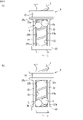
- 4A and 4B are diagrams showing the positional relationship between the retainer and the balls.
- FIG. 4A shows the case where the row of balls is located at the first position
- FIG. 4B shows the case where the row of balls is located at the second position. It is a figure which shows.
- FIG. 5 is a cross-sectional view of essential parts of a ball screw device according to a modification of the first embodiment.
- FIG. 5 is a cross-sectional view of essential parts of a ball screw device according to a modification of the first embodiment.
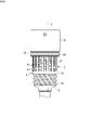
- FIG. 6 is an exploded perspective view of the ball screw device according to the second embodiment.
- FIG. 7 is a cross-sectional view of essential parts of a ball screw device according to a second embodiment.
- FIG. 8 is a diagram showing the retainer arranged on the outer peripheral side of the screw shaft.
- FIG. 9 is a diagram showing a retainer of a ball screw device according to a modification of the second embodiment.
- FIG. 10 is a diagram showing a retainer of a ball screw device according to a second modification of the second embodiment.
- FIG. 11 is an enlarged view of the second inner end face of the connecting annular portion in FIG. 10;
- FIG. 12 is a plan view of the cage developed.
- a ball screw device includes a screw shaft having a first spiral groove on its outer periphery; A ball row including a plurality of balls arranged on the spiral track, and a retainer arranged in an annular space between the screw shaft and the nut to hold the plurality of balls.
- the retainer includes an annular portion arranged in the annular space so as to be rotatable around the center line of the screw shaft and immovable relative to the nut in the axial direction, and one side of the annular portion in the axial direction.
- a plurality of pillars extending from the end face in one axial direction and intersecting the spiral track at a plurality of points, and provided between a pair of pillars adjacent in the circumferential direction among the plurality of pillars to allow the plurality of balls to roll. and a plurality of pockets for holding in.
- the pocket since the pocket is provided between the columns that intersect the spiral track at a plurality of points, the pocket extends along the axial direction and intersects the spiral track at a plurality of points.
- Each ball is held at the intersection of the pocket and the helical track.
- the retainer rotates in response to the movement of the row of balls.
- Each ball then moves axially along the retainer pocket.
- the row of balls can move within the spiral track to the extent that each ball can move axially along the pocket. Therefore, the stroke accompanying the movement of the ball row can be determined by the axial length of the pocket, and the stroke accompanying the movement of the ball row can be increased compared to the case where the coil spring is used as in the above conventional example. can be secured to a large extent.
- the retainer further includes a connecting annular portion that connects ends of the plurality of columns on one side in the axial direction.
- the rigidity of the retainer can be increased by the connecting annular portion.
- a circumferential interval between the pair of pillars may be an interval capable of holding one ball.
- one ball is held at the intersection of the pocket and the spiral track. Therefore, when assembling the ball screw device, each ball may be arranged at the intersection of the pocket and the helical track (first helical groove or second helical groove). Assembly is easier than when a plurality of balls are held in place.
- a circumferential interval between the pair of pillars may be an interval capable of holding a predetermined number of balls, which is two or more. In this case, a plurality of balls are held at intersections of the pockets and the spiral tracks. Therefore, the number of pillars can be reduced compared to the case where one ball is held at the intersection of the pocket and the spiral track.
- the predetermined number of balls are held in each of the plurality of pockets.
- the ball screw device preferably further includes a friction member provided between the nut and the annular portion to provide resistance to rotation of the retainer with respect to the nut.
- the ball screw device functions as a sliding screw when the rotational torque acting between the screw shaft and the nut is so low that the retainer and the nut are held so that they can rotate integrally due to the resistance of the friction member.
- the rotational torque acting between the screw shaft and the nut is large enough to prevent the retainer and the nut from rotating integrally due to the resistance of the friction member, the retainer rotates with respect to the screw shaft and the nut, Functions as a ball screw.
- switching between the state of functioning as a slide screw and the state of functioning as a ball screw can be performed according to the rotational torque acting between the screw shaft and the nut. Further, by adjusting the resistance of the friction member, it is possible to adjust the switching timing between the state of functioning as a sliding screw and the state of functioning as a ball screw.
- the friction member may include a rubber ring interposed between the nut and the outer peripheral surface of the annular portion.
- a frictional force can be generated between the nut and the annular portion with a simple structure, and resistance can be applied to the rotation of the retainer with respect to the nut.
- the nut has a cylindrical inner peripheral surface that accommodates the annular portion radially inward, and a cylindrical inner peripheral surface that extends radially inward from the cylindrical inner peripheral surface and a second radially inner peripheral surface. and a stepped surface connecting with the spiral groove, wherein the friction member presses the annular portion to one side in the axial direction, and presses the stepped surface facing the one end surface of the annular portion and the one end surface.
- Abutting wave washers may be included. In this case, a frictional force can be generated between the nut and the annular portion by contacting and pressing the step surface and the one end surface. Also, by selecting the dimensions and characteristics of the wave washer, it is possible to easily adjust the resistance applied between the nut and the retainer.
- each of the plurality of pockets is defined by side surfaces of the pair of pillars and a first inner end surface of the annular portion, and the first inner end surface extends along the circumferential direction. It has one circumferential surface and a first inclined surface, and the first end portion of the first circumferential surface is located at one of the circumferential both end portions of the first circumferential surface when the pocket is viewed from the front.
- the first helical groove has a smaller axial distance from the top of the groove, and the first inclined surface is a first side surface of the pair of pillars on the first end side, provided so as to connect with the first end, slanted so as to approach the second side of the pair of pillars as it goes from the first side toward the first end, and the first slanted
- the surface is contactable with the ball in contact with the second side surface, and the first circumferential surface is contactable with the ball when the ball contacts the first inclined surface and the second side surface. It is preferable that it is a surface that does not come into contact with the surface.
- the ball moving along the spiral track reaches the first inner end surface, the ball can be brought into contact with the first inclined surface without contacting the first circumferential surface.
- the first inclined surface is inclined so as to approach the second side surface as it goes from the first side surface toward the first end, the groove top located on one side in the axial direction with respect to the ball and the first The angle formed with the inclined surface can be made relatively large. As a result, it is possible to suppress the ball from getting caught between the spiral track and the first inclined surface. Therefore, when the ball moving along the spiral track reaches the first inner end surface and contacts the first inclined surface, it is possible to prevent the ball from being caught between the spiral track and the first inclined surface. can be done.
- the retainer further includes a connecting annular portion that connects ends of the plurality of pillars on one side in the axial direction, and each of the pockets includes side surfaces of the pair of pillars and the annular and a second inner end surface of the connecting annular portion, the second inner end surface having a second circumferential surface along the circumferential direction and a second inclined surface;
- the second end of each of the two circumferential surfaces has a smaller axial distance from the top of the first spiral groove when the pocket is viewed from the front, of the two circumferential ends of the second circumferential surface.
- the second inclined surface which is an end portion, is provided so as to connect a second side surface on the second end side among the side surfaces of the pair of columns and the second end portion, and the second side surface is an end portion.
- the second inclined surface is inclined to approach the first side surface of the pair of side surfaces of the column, and the second inclined surface can contact the ball in contact with the first side surface.
- the second circumferential surface is a surface that does not come into contact with the ball when the ball contacts the second inclined surface and the first side surface.
- the second inclined surface is inclined so as to approach the first side surface as it goes from the second side surface toward the second end, the groove top located on the other side in the axial direction with respect to the ball and the second The angle formed with the inclined surface can be made relatively large. As a result, it is possible to suppress the ball from getting caught between the spiral track and the second inclined surface. Therefore, when the ball moving along the spiral track reaches the second inner end surface and comes into contact with the second inclined surface, it is possible to prevent the ball from getting caught between the spiral track and the second inclined surface. can be done.
- the plurality of second inner end faces are arranged along the lead angle direction of the first spiral groove.
- the plurality of balls can be brought into contact with the plurality of second inner end surfaces at the same timing.
- the force acting from the screw shaft and the nut can be evenly distributed among the plurality of balls, and the biting of the balls can be effectively suppressed.
- a ball screw device which is an embodiment viewed from another point of view, includes a screw shaft having a first spiral groove on its outer periphery, and a second spiral groove forming a spiral track between the first spiral groove and the screw shaft.
- a nut provided on the circumference, a ball row including a plurality of balls arranged on the spiral track, a retainer arranged in an annular space between the screw shaft and the nut and holding the plurality of balls;
- the retainer includes a cylindrical main body portion arranged in the annular space so as to be rotatable around the center line of the screw shaft and immovable relative to the nut in the axial direction, and the main body portion along the circumferential direction. and a plurality of pockets provided in the portion for holding the plurality of balls. The plurality of pockets extend along the axial direction and intersect the spiral track at a plurality of points.
- FIG. 1 is a perspective view of a ball screw device according to a first embodiment
- FIG. 2 is a cross-sectional view of the ball screw device. Note that FIG. 2 is a cross-sectional view along a plane including the center line of the ball screw device.
- This ball screw device 1 is used for a brake device of a vehicle such as an automobile, a power transmission device including a multi-plate clutch, and the like.
- a ball screw device 1 includes a screw shaft 2 , a nut 4 provided on the outer peripheral side of the screw shaft 2 , a plurality of balls 6 , and a retainer 8 that holds the plurality of balls 6 .
- the direction parallel to the center line C of the screw shaft 2 is defined as the axial direction
- the direction orthogonal to the center line C is defined as the radial direction
- the direction along the circle centered on the center line C is defined as the circumferential direction.
- direction. 1 and 2 the side where the snap ring 9 is not provided in the opening of the nut 4 in the axial direction is defined as one axial side
- the side where the snap ring 9 is provided is defined as the other axial side.
- the screw shaft 2 is inserted through the nut 4 and has a first spiral groove 10 on its outer circumference.
- the nut 4 is a cylindrical member.
- the centerline of the nut 4 coincides with the centerline C.
- the nut 4 has a second spiral groove 12 on its inner circumference.
- a cylindrical inner peripheral surface 4a is provided at the end of the inner periphery of the nut 4 on the other side in the axial direction.
- the first helical groove 10 of the screw shaft 2 and the second helical groove 12 of the nut 4 constitute a helical track 14 in which a plurality of balls 6 are arranged.
- the outer diameter dimension of the groove top portion 10 a of the first spiral groove 10 is smaller than the inner diameter dimension of the groove top portion 12 a of the second spiral groove 12 . Therefore, an annular space K is provided between the screw shaft 2 and the nut 4 .
- a retainer 8 is arranged in an annular space K between the screw shaft 2 and the nut 4 .
- the retainer 8 comprises an annular portion 20 and a plurality of posts 22 .
- the annular portion 20 is accommodated radially inward of the cylindrical inner peripheral surface 4a.
- the annular portion 20 is arranged between the cylindrical inner peripheral surface 4 a and the screw shaft 2 .
- An annular groove 4b in which a retaining ring 9 is fitted is provided in the cylindrical inner peripheral surface 4a.
- One end face 20 a on one axial side of the annular portion 20 faces the stepped face 24 of the nut 4 .
- the step surface 24 is a surface that extends radially inward from the cylindrical inner peripheral surface 4 a and connects between the cylindrical inner peripheral surface 4 a and the second spiral groove 12 . Further, the other end surface 20 b on the other axial side of the annular portion 20 faces the inner surface 9 a of the retaining ring 9 .
- a slight clearance is provided between the inner peripheral surface 20c of the annular portion 20 and the groove top portion 10a of the first spiral groove 10 of the screw shaft 2. As shown in FIG. A slight clearance is also provided between the outer peripheral surface 20d of the annular portion 20 and the cylindrical inner peripheral surface 4a. Thereby, the annular portion 20 is arranged in the annular space K so as to be rotatable around the center line C and axially immovable relative to the nut 4 .
- An outer peripheral surface 20d of the annular portion 20 is provided with an outer peripheral groove 20d1.
- a friction member 26 is provided in the outer peripheral groove 20d1.
- the friction member 26 is a rubber ring.
- the friction member 26 is fitted in the outer peripheral groove 20d1.
- the friction member 26 is interposed between the cylindrical inner peripheral surface 4a and the outer peripheral groove 20d1, and is in contact with the cylindrical inner peripheral surface 4a and the outer peripheral groove 20d1. That is, the friction member 26 is provided between the nut 4 and the annular portion 20 .
- the friction member 26 provides resistance to the rotation of the retainer 8 with respect to the nut 4 by the frictional force generated by contacting the cylindrical inner peripheral surface 4a and the outer peripheral groove 20d1.
- the retainer 8 rotates integrally with the nut 4, causing the retainer 8 to rotate relatively. is greater than the resistance of the friction member 26, the retainer 8 can rotate relative to the nut 4.
- a plurality of columns 22 of the retainer 8 extend from one end surface 20a of the annular portion 20 to one side in the axial direction.
- the retainer 8 of this embodiment comprises three posts 22 .
- the three pillars 22 are arranged at regular intervals in the circumferential direction.
- FIG. 3(a) is a perspective view showing the retainer 8 arranged on the outer peripheral side of the screw shaft 2
- FIG. 3(b) is a perspective view showing the retainer 8.
- FIG. 1 As shown in FIGS. 2 and 3, the three pillars 22 extend across between the groove crest 10a of the first spiral groove 10 of the screw shaft 2 and the groove crest 12a of the second spiral groove 12 of the nut 4. It extends in the axial direction and intersects the spiral track 14 at a plurality of points.
- the retainer 8 also includes a connecting annular portion 30 that connects the ends 22a of the columns 22 on one side in the axial direction.
- the centerline of the connecting annular portion 30 coincides with the centerline C and is concentric with the annular portion 20 .
- One axial end surface 30 a of the connecting annular portion 30 substantially coincides with the axial one end surface 4 c of the nut 4 . In this manner, the connecting annular portion 30 is provided at one end portion of the nut 4 in the axial direction.
- the retainer 8 further comprises a plurality of pockets 32 that hold a plurality of balls 6 rollably.
- the pocket 32 is provided between a pair of pillars 22 adjacent in the circumferential direction among the three pillars 22 . Therefore, the retainer 8 of this embodiment has three pockets 32 .
- the pocket 32 is a rectangular space surrounded by a pair of pillars 22 adjacent in the circumferential direction, the annular portion 20 and the connecting annular portion 30 . Therefore, the pocket 32 extends along the axial direction and intersects the spiral track 14 at a plurality of points.
- the pocket 32 is defined by the side surfaces 22b of a pair of circumferentially adjacent columns 22, the first inner end surface 32a of the annular portion 20, and the second inner end surface 32b of the connecting annular portion 30.
- the first inner end surface 32 a is an end surface on one side in the axial direction of the annular portion 20 .
- the second inner end surface 32b is an end surface of the connecting annular portion 30 on the other side in the axial direction.
- the pair of side surfaces 22b extend along the axial direction.
- a plurality of balls 6 are arranged in a spiral track 14 to form a ball row L.
- the ball row L includes six balls 6 in this embodiment.
- the circumferential interval between a pair of pillars 22 adjacent in the circumferential direction is the interval that allows two balls 6 to be held. Therefore, three pillars 22 intervene in the row L of balls.
- the three pillars 22 intervene so as to divide the balls 6 of the ball row L arranged in the row longitudinal direction into three. That is, each of the three pockets 32 holds two balls 6 aligned in the row longitudinal direction.
- the ball screw device 1 functions as a ball screw as the ball train L moves within the spiral track 14 .
- the balls 6 are held in the pockets 32 , the movement range of the ball row L in the axial direction is limited by the retainer 8 .
- the ball 6 a located at the end of the ball row L on the other side in the axial direction among the six balls 6 is the first inner end surface 32 a of the annular portion 20 and the side surface of the column 22 . 22b, the axial position of the ball row L in the retainer 8 is the position closest to the other side in the axial direction (first position).
- the nut 4 is abbreviate
- the ball screw device 1 rotates the screw shaft 2 relative to the nut 4 and functions as a ball screw while the row of balls L moves from the first position to the second position.
- the screw shaft 2 is further rotated relative to the nut 4 after the ball train L reaches the second position from the first position, the movement of the ball train L in the axial direction is restricted.
- 1 does not function as a ball screw, but functions as a slide screw.
- the ball screw device 1 functions as a ball screw even while the row of balls L moves from the second position to the first position.
- the screw shaft 2 is further rotated relative to the nut 4 after the ball row L reaches the first position from the second position, the movement of the ball row L in the axial direction is also restricted in this case.
- the ball screw device 1 does not function as a ball screw, but functions as a slide screw.
- the ball screw device 1 rotates the screw shaft 2 relative to the nut 4 and functions as a ball screw while the row of balls L moves between the first position and the second position in the retainer 8. do.
- the ball screw device 1 functions as a slide screw.
- the ball screw device 1 configured as described above applies a rotational force to the screw shaft 2 and causes the screw shaft 2 to rotate relative to the nut 4 , thereby moving the nut along the axial direction and rotating the screw shaft 2 .
- a rotational force used for converting motion into linear motion.
- the ball screw device 1 functions as a ball screw to transmit power to the screw shaft 2.
- the nut 4 is moved in the axial direction. That is, during the stroke of the ball screw device 1, the rotational force applied to the screw shaft 2 is decelerated while the row of balls L moves between the first position and the second position.
- the ball screw device 1 functions as a sliding screw and moves the nut 4 in the axial direction according to the rotation applied to the screw shaft 2 .
- the pockets 32 are provided between the columns 22 that intersect the spiral track 14 at a plurality of points, the pockets 32 extend along the axial direction and intersect the spiral track 14 at a plurality of points.
- Each ball 6 is held at the point where the pocket 32 and the spiral track 14 intersect.
- the retainer 8 rotates according to the movement of the row of balls L.
- each ball 6 moves axially along the pocket 32 of the retainer 8 . Therefore, the ball row L can move within the spiral track 14 within a range in which each ball 6 can move axially along the pocket 32 .
- the stroke that accompanies the movement of the ball row L can be determined by the axial length of the pocket 32, and the stroke that accompanies the movement of the ball row can be compared with the conventional example using the coil spring. can be secured to a greater extent.
- the ball screw device 1 can be switched between a state in which it functions as a slide screw and a state in which it functions as a ball screw. You can adjust the switching timing. For example, when the screw shaft 2 and the nut 4 are relatively rotated to move the nut 4 to the other side in the axial direction from the state shown in FIG. When the applied rotational torque is relatively small, the friction member 26 holds the retainer 8 rotatably integrally with the nut 4 by the resistance generated by contacting the nut 4 and the annular portion 20 . When the retainer 8 does not rotate relative to the nut 4, the ball rows L do not move within the spiral track 14, so the ball screw device 1 functions as a slide screw.
- the friction member 26 is provided between the nut 4 and the annular portion 20 of the retainer 8, switching between the state of functioning as a slide screw and the state of functioning as a ball screw can be performed. It can be done according to the rotational torque acting between the screw shaft 2 and the nut 4 . Further, by adjusting the resistance of the friction member 26, it is possible to adjust the switching timing between the state of functioning as a sliding screw and the state of functioning as a ball screw.
- the friction member 26 is composed of a rubber ring, a frictional force can be generated between the nut 4 and the annular portion 20 with a simple configuration, and the rotation of the retainer 8 with respect to the nut 4 is resisted. can be granted.
- the retainer 8 since the retainer 8 includes the connecting annular portion 30 at the tip 22a of the column 22, the rigidity of the retainer 8 can be increased. Further, by providing the connecting annular portion 30, the ball 6b at the end portion on the one axial side in the ball row L when the axial position of the ball row L is the first position moves further to the one axial side. can be more tightly bounded.
- the circumferential interval between a pair of pillars 22 adjacent in the circumferential direction is an interval capable of holding two balls 6, the position where the pocket 32 and the spiral track 14 intersect is , two balls 6 are held. Therefore, the number of pillars 22 can be reduced compared to the case where one ball 6 is held at the intersection of the pocket 32 and the spiral track 14 .
- FIG. 5 is a cross-sectional view of essential parts of a ball screw device 1 according to a modification of the first embodiment.
- the friction member 26 is configured by a rubber ring, but in this modified example, the friction member 26 is configured by a wave washer.
- the friction member 26 of this embodiment is interposed between the other end surface 20b of the annular portion 20 and the inner side surface 9a of the retaining ring 9, and presses the annular portion 20 (retainer 8) to one side in the axial direction.
- the friction member 26 brings the stepped surface 24 of the nut 4 into contact with the one end surface 20a of the annular portion 20, and the frictional force between the stepped surface 24 and the one end surface 20a causes the retainer 8 to move against the nut 4. gives resistance to the rotation of
- a frictional force can be generated between the nut 4 and the annular portion 20 by bringing the stepped surface 24 and the one end surface 20a into contact and pressing them. Further, by selecting the dimensions and characteristics of the friction member 26, which is a wave washer, the frictional force between the step surface 24 and the one end surface 20a can be easily adjusted. The resistance imparted between can be easily adjusted. As a result, it is possible to easily adjust the switching timing between the state of functioning as a sliding screw and the state of functioning as a ball screw.
- FIG. 6 is an exploded perspective view of the ball screw device 1 according to the second embodiment
- FIG. 7 is a cross-sectional view of the essential parts of the ball screw device 1 according to the second embodiment. 6 and 7, the ball 6 is omitted.
- the ball screw device 1 of this embodiment also has a screw shaft 2 having a first spiral groove 10 on its outer periphery and a second spiral groove forming a spiral raceway 14 between the first spiral groove 10 and the first spiral groove 10 . 12 on the inner circumference, a ball row L including a plurality of balls 6 arranged on a spiral track 14, and a plurality of balls 6 arranged in an annular space K between the screw shaft 2 and the nut 4. and a retainer 8 that holds the Further, the retainer 8 includes an annular portion 20 arranged in the annular space K so as to be rotatable around the center line C of the screw shaft 2 and immovable relative to the nut 4 in the axial direction.
- a plurality of pillars 22 extending from one end face 20 a on one side to one side in the axial direction and intersecting the spiral track 14 at a plurality of points;
- a plurality of pockets 32 are provided between a pair of pillars adjacent to each other in the direction and hold a plurality of balls 6 in a rollable manner.
- This embodiment has a sleeve 36 arranged on the other side in the axial direction of the retainer 8, and the circumferential interval between a pair of pillars 22 adjacent in the circumferential direction is such that one ball 6 can be held. is different from the first embodiment.
- the sleeve 36 is arranged on the outer peripheral side of the screw shaft 2 and is internally fitted and fixed to the cylindrical inner peripheral surface 4 a of the nut 4 .
- One end face 36 a on one side in the axial direction of the sleeve 36 abuts the other end face 20 b of the annular portion 20 .
- the annular portion 20 is made immovable relative to the nut 4 in the axial direction by the step surface 24 of the nut 4 and the one end surface 36 a of the sleeve 36 .
- FIG. 8 is a diagram showing the retainer 8 arranged on the outer peripheral side of the screw shaft 2.
- the retainer 8 of this embodiment has 14 pillars 22 .
- the retainer 8 thus has 14 pockets 32 .
- the ball row L of this embodiment includes 14 balls 6, for example.
- Each pocket 32 thus holds one ball 6 .
- one ball 6 is held at the intersection of the pocket 32 and the spiral track 14 . Therefore, when assembling the ball screw device 1 , each ball 6 may be arranged at the intersection of the pocket 32 and the helical track 14 (first helical groove 10 or second helical groove 12 ). As compared with the case where a plurality of balls 6 are held at the intersection of the spiral track 14 and the spiral track 14, the assembly becomes easier.
- FIG. 9 is a diagram showing a retainer 8 of a ball screw device 1 according to a first modified example of the second embodiment.
- the first inner end surface 32a of the annular portion 20 is configured to include a circumferential surface 32a1 along the circumferential direction and an inclined surface 32a2 inclined with respect to the circumferential surface 32a1.
- the second embodiment is characterized in that the second inner end surface 32b of the connecting annular portion 30 includes a circumferential surface 32b1 along the circumferential direction and an inclined surface 32b2 inclined with respect to the circumferential surface 32b1.
- an inclined surface 32a2 is provided on the side of the one end 32a11 that has a smaller axial distance from the groove top portion 10a when the pocket 32 is viewed from the front. ing.
- the one end portion 32a11 is an end portion on one side in the circumferential direction of the both circumferential direction end portions of the circumferential direction surface 32a1.
- the inclined surface 32a2 is provided so as to connect one end portion 32a11 of the circumferential surface 32a1 and the side surface 22b of the column 22 .
- the inclined surface 32a2 is inclined in one axial direction from the one end 32a11 toward the side surface 22b of the column 22 . Therefore, the angle formed by the inclined surface 32a2 and the side surface 22b is 90 degrees or more.
- the inclined surface 32b2 is located on the side of the other end 32b11 which is closer to the groove crest 10a in the axial direction. is provided.
- the other end portion 32b11 is an end portion on the other side in the circumferential direction among both circumferential direction end portions of the circumferential surface 32b1.
- the inclined surface 32b2 is provided so as to connect the other end portion 32b11 of the circumferential surface 32b1 and the side surface 22b of the column 22 .
- the inclined surface 32b2 is inclined toward the other side in the axial direction from the other end portion 32b11 toward the side surface 22b. Therefore, the angle formed by the inclined surface 32b2 and the side surface 22b is 90 degrees or more.
- the axial position of the ball row L is located at the second position, and when the ball 6b located at one end in the axial direction of the ball row L contacts the second inner end surface 32b and the side surface 22b of the column 22, the ball 6b contacts the side surface 22b of the column 22 and the inclined surface 32b2 of the second inner end surface 32b. At this time, since the angle formed by the inclined surface 32b2 and the side surface 22b is 90 degrees or more, it is possible to prevent the ball 6b from getting caught between the inclined surface 32b2 and the side surface 22b.
- FIG. 10 is a diagram showing a retainer 8 of a ball screw device 1 according to a second modified example of the second embodiment.
- This second modification is the first modification in that the plurality of first inner end surfaces 32a and the plurality of second inner end surfaces 32b are arranged along the lead angle direction of the spiral track 14 (first spiral groove 10). differ from
- the first inner end surface 32a of the annular portion 20 includes a circumferential surface 32a1 along the circumferential direction and an inclined surface 32a2.
- the second inner end surface 32b of is configured to include a circumferential surface 32b1 along the circumferential direction and an inclined surface 32b2.
- one end portion 32a11 (first end portion) is an end portion on one side in the circumferential direction of the circumferential surface 32a1 (first circumferential surface).
- the other end portion 32a12 is an end portion on the other side in the circumferential direction of the circumferential surface 32a1.
- the axial distance between the one end portion 32a11 and the groove top portion 10a when the pocket 32 is viewed from the front is smaller than the axial distance between the other end portion 32a12 and the groove top portion 10a. That is, the one end portion 32a11 of the circumferential surface 32a1 is the end portion having a smaller axial distance from the groove top portion 10a when the pocket 32 is viewed from the front, among the both end portions of the circumferential surface 32a1.
- the inclined surface 32a2 (first inclined surface) is provided so as to connect the first side surface 22b1 and the one end portion 32a11.
- the inclined surface 32a2 connects the end portion 22b11 of the first side surface 22b1 and the one end portion 32a11.
- the inclined surface 32a2 is inclined so as to approach the second side surface 22b2 as it goes from the first side surface 22b1 toward the one end portion 32a11.
- the first side surface 22 b 1 is the side surface 22 b on the one end 32 a 11 side of the side surfaces 22 b of the pair of columns 22 that define the pocket 32 .
- the second side surface 22b2 is the other side surface of the side surfaces 22b of the pair of pillars 22 .
- the angle formed by the inclined surface 32a2 and the first side surface 22b1 is 90 degrees or more.
- the inclined surface 32a2 can contact the ball 6 that is in contact with the second side surface 22b2.
- the circumferential surface 32a1 is a surface that does not come into contact with the ball 6 when the ball 6 contacts the inclined surface 32a2 and the second side surface 22b2.
- the axial distance between the other end portion 32b11 and the groove top portion 10a when the pocket 32 is viewed from the front is smaller than the axial distance between the one end portion 32b12 and the groove top portion 10a.
- the one end portion 32b12 is an end portion on one side in the circumferential direction of the circumferential surface 32b1.
- the other end portion 32b11 (second end portion) is the end portion on the other circumferential side of the circumferential surface 32b1 (second circumferential surface). That is, the other end portion 32b11 of the circumferential surface 32b1 is the end portion having a smaller axial distance from the groove top portion 10a when the pocket 32 is viewed from the front, among both end portions of the circumferential surface 32b1.
- the inclined surface 32b2 (second inclined surface) is provided so as to connect the second side surface 22b2 and the other end portion 32b11.
- the inclined surface 32b2 connects the end portion 22b21 of the second side surface 22b2 and the other end portion 32b11.
- the inclined surface 32b2 is inclined so as to approach the first side surface 22b1 from the second side surface 22b2 toward the other end portion 32b11.
- the second side surface 22b2 is the side surface 22b on the other end 32b11 side of the side surfaces 22b of the pair of columns 22 that define the pocket 32 .
- the angle formed by the inclined surface 32b2 and the second side surface 22b2 is 90 degrees or more.
- the inclined surface 32b2 can contact the ball 6 that is in contact with the first side surface 22b1.
- the circumferential surface 32b1 is a surface that does not come into contact with the ball 6 when the ball 6 contacts the inclined surface 32b2 and the first side surface 22b1.
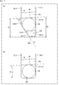
- FIG. 11 (a) in FIG. 11 is an enlarged view of the second inner end surface 32b of the connecting annular portion 30 in FIG. FIG. 11(a) shows the ball 6b when the ball row L is positioned at the second position.
- the ball 6b is the ball 6 located at one end of the ball row L in the axial direction, as described above.
- the axial distance W1 is the axial distance between the other end portion 32b11 and the edge portion 40 of the groove top portion 10a.
- the axial distance W2 is the axial distance between the one end portion 32b12 and the edge portion 40 of the groove top portion 10a.
- the first spiral groove 10 has a lead angle that slopes down to the left in the plane of the paper. Therefore, the axial distance W1 is smaller than the axial distance W2.
- the axial distances W1 and W2 are values based on the edge portion 40 of the groove top portion 10a on the other axial side of the ball 6b. However, if the portion of the spiral track 14 is parallel to the lead angle direction, the portion of the groove top portion 10a other than the edge portion 40 can be used as the reference for the axial distances W1 and W2.
- the angle ⁇ 2 formed by the edge 40 of the groove top portion 10a and the second inner end surface 32b is The lead angle is approximately the same as the lead angle of one spiral groove 10 (helical track 14), which is an extremely acute angle.
- the edge 40 and the second inner end surface 32b form a wedge shape. Therefore, in FIG. 11(b), when the ball 6b moving along the spiral track 14 reaches the second inner end surface 32b, the ball 6b is caught between the edge 40 and the second inner end surface 32b. I'll put it away. If the ball 6b gets caught between the edge portion 40 and the second inner end surface 32b, the ball 6b cannot slide on the spiral track 14, and the function as a sliding screw is impaired.
- the second inner end surface 32b has the inclined surface 32b2, so that the angle ⁇ 1 is less than the angle ⁇ 2 when the second inner end surface 32b does not have the inclined surface 32b2. You can make it bigger. As a result, it is possible to prevent the ball 6b from being bitten, and to prevent the function of the slide screw from being impaired.
- the angle ⁇ 1 is determined by the angle ⁇ formed by the first side surface 22b1 and the inclined surface 32b2. By setting the angle ⁇ to an appropriate angle, the inclined surface 32b2 is provided on the second inner end surface 32b, and the biting of the ball 6b can be suppressed.
- the angle ⁇ 1 is determined by the lead angle of the helical track 14, the coefficient of friction between the balls 6 and the helical track 14, the coefficient of friction between the balls 6 and the retainer 8, and the like.
- the angle ⁇ 1 is 10 degrees or less, there is a high possibility that the ball 6b will get caught. Therefore, it is preferable that the angle ⁇ 1 is 20 degrees or more.
- the angle ⁇ 1 is more preferably 30 degrees or more.
- the circumferential length of the circumferential surface 32b1 (the length between the one end 32b12 and the other end 32b11) is preferably smaller than the diameter of the ball 6b.
- the inclined surface 32b2 can be reliably brought into contact with the ball 6b.
- the first inner end face 32a has the same configuration. That is, since the first inner end surface 32a has the inclined surface 32a2, the groove top portion 10a located on one side in the axial direction with respect to the end ball 6a when the ball row L is at the first position The angle ⁇ 1 formed with the inner end surface 32a can be made relatively large. As a result, when the ball 6a moving along the spiral track 14 reaches the first inner end surface 32a and contacts the inclined surface 32a2, the first spiral groove 10 (the spiral track 14) and the first inner end surface 32a ( It is possible to suppress the ball 6a from being caught between the inclined surface 32a2).
- FIG. 12 is a plan view of the retainer 8 developed.
- an imaginary line D2 on the outer peripheral surface 42 of the retainer 8 passes through the plurality of other end portions 32a12 of the plurality of first inner end surfaces 32a. Therefore, the plurality of first inner end faces 32a are arranged along the imaginary line D2.
- a virtual line D3 on the outer peripheral surface 42 passes through the plurality of one end portions 32b12 of the plurality of second inner end surfaces 32b. Therefore, the plurality of second inner end faces 32b are arranged along the imaginary line D3.
- the virtual line D2 and the virtual line D3 are parallel to the line D1 parallel to the lead angle direction of the spiral track 14 (first spiral groove 10).
- the plurality of first inner end faces 32a and the plurality of second inner end faces 32b are arranged along the lead angle direction of the spiral track 14 (first spiral groove 10). Also, the virtual lines D2 and D3 are parallel to each other. Therefore, the plurality of pockets 32 are arranged so as to be offset along the lead angle direction.
- FIG. 12 shows the case where the ball row L is positioned at the second position. Therefore, the ball 6b at the end of the ball row L is in contact with the inclined surface 32b2 of the second inner end surface 32b.
- the plurality of second inner end surfaces 32b are arranged along the lead angle direction of the spiral track 14, when the ball 6b comes into contact with the inclined surface 32b2, the other balls 6 also come into contact with the same timing as the ball 6b. , abuts on the inclined surface 32b2.
- the plurality of second inner end faces 32b are arranged along the circumferential direction.
- the movement of the ball row L along the spiral track 14 is restricted.
- the force from the screw shaft 2 and the nut 4 concentrates on the ball 6b, and the force from the screw shaft 2 and the nut 4 does not act on the other balls 6 significantly.
- FIG. 12 illustrates the case where the ball row L is positioned at the second position
- the force acting from the screw shaft 2 and the nut 4 can be evenly distributed to the plurality of balls 6, and the biting of the balls 6 can be suppressed more effectively.
- the ball screw device 1 when the screw shaft 2 and the nut 4 rotate relative to each other and the retainer 8 rotates, the ball rows L move within the spiral raceway 14 . Thereby, the ball screw device 1 functions as a ball screw.
- the ball screw device 1 when the ball screw device 1 is operated so as to repeatedly reciprocate the row of balls L, the position of the row of balls L may gradually shift.
- a reference position and a predetermined position different from the reference position are set as relative positions of the screw shaft 2 and the nut 4, and the screw shaft 2 and the nut 4 are reciprocated between the reference position and the predetermined position. explain.
- the ball row L is arranged at the first position when the screw shaft 2 and the nut 4 are at the reference position, and the ball row L is arranged at an intermediate position between the first position and the second position when the screw shaft 2 and the nut 4 are at the predetermined position.
- the ball row L may not return to the first position, or the ball row L may deviate from the intermediate position even though the screw shaft 2 and the nut 4 are in the predetermined positions.
- Such a positional deviation of the ball row L is caused by a difference in load, stroke amount, etc. between the outward and return paths when the ball row L moves in the spiral track 14 .
- Such a difference between the outward path and the return path is caused by the elastic hysteresis of the metal material forming the screw shaft 2 and the nut 4, the shape of the spiral track 14, the lead angle, and the like.
- the biting of the balls 6 described above also contributes to the positional deviation of the row L of balls.
- the retainer 8 prevents the balls 6 from being caught, Limits axial movement along track 14 .
- the balls 6 come into contact with the inclined surface 32a2 of the first inner end surface 32a and the movement of the row of balls L is restricted. be.
- the position of the ball row L is shifted, the movement of the ball row L is restricted by the inclined surface 32a2, and the position of the ball row L is corrected to the first position.
- the retainer 8 restricts the axial movement of the ball rows L along the spiral track 14, even if the ball rows L are misaligned, the misalignment can be corrected. can be done. Further, since it is possible to prevent the ball 6 from being caught when the ball row L reaches the first position or the second position, it is possible to prevent the ball row L from being displaced.
- the retainer 8 included in the ball screw device 1 shown in each of the above embodiments includes an annular portion 20, a plurality of pillars 22, a connecting annular portion 30, and a plurality of pockets 32.
- the portion 20, the plurality of pillars 22, and the connecting annular portion 30 constitute a cylindrical body portion.
- This cylindrical main body is arranged in the annular space K so as to be rotatable around the center line C of the screw shaft 2 and axially immovable relative to the nut 4 .
- the pockets 32 are provided in this body portion, extend along the axial direction, and intersect the spiral track 14 at a plurality of points.
- first and second modifications of the second embodiment the case where the inclined surfaces 32a2 and 32b2 are provided on both the first inner end surface 32a and the second inner end surface 32b is illustrated. At least one of the first inner end surface 32a and the second inner end surface 32b may be provided with an inclined surface.
Landscapes
- Engineering & Computer Science (AREA)
- General Engineering & Computer Science (AREA)
- Mechanical Engineering (AREA)
- Transmission Devices (AREA)
Priority Applications (1)
| Application Number | Priority Date | Filing Date | Title |
|---|---|---|---|
| JP2023520758A JP7708181B2 (ja) | 2021-05-13 | 2021-12-10 | ボールねじ装置 |
Applications Claiming Priority (2)
| Application Number | Priority Date | Filing Date | Title |
|---|---|---|---|
| JP2021-081402 | 2021-05-13 | ||
| JP2021081402 | 2021-05-13 |
Publications (1)
| Publication Number | Publication Date |
|---|---|
| WO2022239286A1 true WO2022239286A1 (ja) | 2022-11-17 |
Family
ID=84028084
Family Applications (1)
| Application Number | Title | Priority Date | Filing Date |
|---|---|---|---|
| PCT/JP2021/045502 Ceased WO2022239286A1 (ja) | 2021-05-13 | 2021-12-10 | ボールねじ装置 |
Country Status (2)
| Country | Link |
|---|---|
| JP (1) | JP7708181B2 (https=) |
| WO (1) | WO2022239286A1 (https=) |
Cited By (1)
| Publication number | Priority date | Publication date | Assignee | Title |
|---|---|---|---|---|
| CN116379120A (zh) * | 2023-04-24 | 2023-07-04 | 黑龙江强工科技有限责任公司 | 一种高精度丝杠丝母定位调整机构及应用其的木工四面刨 |
Citations (4)
| Publication number | Priority date | Publication date | Assignee | Title |
|---|---|---|---|---|
| JPS6053217B2 (ja) * | 1978-12-11 | 1985-11-25 | 光洋精工株式会社 | ボ−ルネジ装置 |
| JP2003074664A (ja) * | 2001-09-05 | 2003-03-12 | Koyo Seiko Co Ltd | ボールねじ装置 |
| US20110120247A1 (en) * | 2009-10-28 | 2011-05-26 | Schaeffler Technologies Gmbh & Co. Kg | Ball screw, in particular for a parking brake of a motor vehicle |
| JP2017020517A (ja) * | 2015-07-07 | 2017-01-26 | Ntn株式会社 | 保持器付きボールねじ |
Family Cites Families (1)
| Publication number | Priority date | Publication date | Assignee | Title |
|---|---|---|---|---|
| JP6053217B2 (ja) | 2015-09-03 | 2016-12-27 | 株式会社大一商会 | 遊技機 |
-
2021
- 2021-12-10 JP JP2023520758A patent/JP7708181B2/ja active Active
- 2021-12-10 WO PCT/JP2021/045502 patent/WO2022239286A1/ja not_active Ceased
Patent Citations (4)
| Publication number | Priority date | Publication date | Assignee | Title |
|---|---|---|---|---|
| JPS6053217B2 (ja) * | 1978-12-11 | 1985-11-25 | 光洋精工株式会社 | ボ−ルネジ装置 |
| JP2003074664A (ja) * | 2001-09-05 | 2003-03-12 | Koyo Seiko Co Ltd | ボールねじ装置 |
| US20110120247A1 (en) * | 2009-10-28 | 2011-05-26 | Schaeffler Technologies Gmbh & Co. Kg | Ball screw, in particular for a parking brake of a motor vehicle |
| JP2017020517A (ja) * | 2015-07-07 | 2017-01-26 | Ntn株式会社 | 保持器付きボールねじ |
Cited By (1)
| Publication number | Priority date | Publication date | Assignee | Title |
|---|---|---|---|---|
| CN116379120A (zh) * | 2023-04-24 | 2023-07-04 | 黑龙江强工科技有限责任公司 | 一种高精度丝杠丝母定位调整机构及应用其的木工四面刨 |
Also Published As
| Publication number | Publication date |
|---|---|
| JP7708181B2 (ja) | 2025-07-15 |
| JPWO2022239286A1 (https=) | 2022-11-17 |
Similar Documents
| Publication | Publication Date | Title |
|---|---|---|
| JP5201272B2 (ja) | 無段変速機 | |
| JP6390905B2 (ja) | ボールねじ装置 | |
| JP4526789B2 (ja) | 制動ローラを備えた長手方向移動ユニット | |
| KR101953941B1 (ko) | 크로스 롤러 베어링 | |
| JP2009293759A (ja) | 回転伝達装置 | |
| JP2016094961A (ja) | 伸縮自在シャフト | |
| CN111022598A (zh) | 滚珠螺杆装置 | |
| JP2009115120A (ja) | ボールスプライン | |
| WO2022239286A1 (ja) | ボールねじ装置 | |
| CN110100108B (zh) | 三球销式等速万向节 | |
| JP2019011818A (ja) | 回転伝達装置 | |
| US11585417B2 (en) | Ball screw nut with end stop for reset spring | |
| JP2015197124A (ja) | 直動案内付クランパ | |
| JP3726471B2 (ja) | ボールねじ | |
| JP2801153B2 (ja) | 回転摩擦装置 | |
| JP4831427B2 (ja) | トロイダル型無段変速機 | |
| JP3656440B2 (ja) | コマ式ボールねじ | |
| JPH03277822A (ja) | 等速ジョイント | |
| JP4230378B2 (ja) | 軸継手 | |
| JP2007092932A (ja) | 等速自在継手のシャフト抜け止め構造 | |
| JP2025025413A (ja) | 摩擦伝動装置 | |
| JP2025025414A (ja) | 摩擦伝動装置 | |
| US12152640B1 (en) | Cam clutch | |
| WO2025033460A1 (ja) | 摩擦伝動装置 | |
| JPH0349301Y2 (https=) |
Legal Events
| Date | Code | Title | Description |
|---|---|---|---|
| 121 | Ep: the epo has been informed by wipo that ep was designated in this application |
Ref document number: 21942014 Country of ref document: EP Kind code of ref document: A1 |
|
| ENP | Entry into the national phase |
Ref document number: 2023520758 Country of ref document: JP Kind code of ref document: A |
|
| NENP | Non-entry into the national phase |
Ref country code: DE |
|
| 122 | Ep: pct application non-entry in european phase |
Ref document number: 21942014 Country of ref document: EP Kind code of ref document: A1 |