WO2022234743A1 - 動画像処理装置、動画像処理方法及びプログラム、動画像表示システム - Google Patents
動画像処理装置、動画像処理方法及びプログラム、動画像表示システム Download PDFInfo
- Publication number
- WO2022234743A1 WO2022234743A1 PCT/JP2022/014346 JP2022014346W WO2022234743A1 WO 2022234743 A1 WO2022234743 A1 WO 2022234743A1 JP 2022014346 W JP2022014346 W JP 2022014346W WO 2022234743 A1 WO2022234743 A1 WO 2022234743A1
- Authority
- WO
- WIPO (PCT)
- Prior art keywords
- display position
- moving image
- display
- information
- image processing
- Prior art date
- Legal status (The legal status is an assumption and is not a legal conclusion. Google has not performed a legal analysis and makes no representation as to the accuracy of the status listed.)
- Ceased
Links
Images



Classifications
-
- A—HUMAN NECESSITIES
- A61—MEDICAL OR VETERINARY SCIENCE; HYGIENE
- A61B—DIAGNOSIS; SURGERY; IDENTIFICATION
- A61B8/00—Diagnosis using ultrasonic, sonic or infrasonic waves
- A61B8/12—Diagnosis using ultrasonic, sonic or infrasonic waves in body cavities or body tracts, e.g. by using catheters
-
- A—HUMAN NECESSITIES
- A61—MEDICAL OR VETERINARY SCIENCE; HYGIENE
- A61B—DIAGNOSIS; SURGERY; IDENTIFICATION
- A61B8/00—Diagnosis using ultrasonic, sonic or infrasonic waves
- A61B8/46—Ultrasonic, sonic or infrasonic diagnostic devices with special arrangements for interfacing with the operator or the patient
- A61B8/461—Displaying means of special interest
- A61B8/463—Displaying means of special interest characterised by displaying multiple images or images and diagnostic data on one display
-
- A—HUMAN NECESSITIES
- A61—MEDICAL OR VETERINARY SCIENCE; HYGIENE
- A61B—DIAGNOSIS; SURGERY; IDENTIFICATION
- A61B8/00—Diagnosis using ultrasonic, sonic or infrasonic waves
- A61B8/46—Ultrasonic, sonic or infrasonic diagnostic devices with special arrangements for interfacing with the operator or the patient
- A61B8/467—Ultrasonic, sonic or infrasonic diagnostic devices with special arrangements for interfacing with the operator or the patient characterised by special input means
- A61B8/469—Ultrasonic, sonic or infrasonic diagnostic devices with special arrangements for interfacing with the operator or the patient characterised by special input means for selection of a region of interest
-
- G—PHYSICS
- G06—COMPUTING OR CALCULATING; COUNTING
- G06T—IMAGE DATA PROCESSING OR GENERATION, IN GENERAL
- G06T11/00—Two-dimensional [2D] image generation
- G06T11/60—Creating or editing images; Combining images with text
-
- G—PHYSICS
- G06—COMPUTING OR CALCULATING; COUNTING
- G06T—IMAGE DATA PROCESSING OR GENERATION, IN GENERAL
- G06T7/00—Image analysis
- G06T7/70—Determining position or orientation of objects or cameras
-
- G—PHYSICS
- G06—COMPUTING OR CALCULATING; COUNTING
- G06V—IMAGE OR VIDEO RECOGNITION OR UNDERSTANDING
- G06V10/00—Arrangements for image or video recognition or understanding
- G06V10/20—Image preprocessing
- G06V10/25—Determination of region of interest [ROI] or a volume of interest [VOI]
-
- G—PHYSICS
- G06—COMPUTING OR CALCULATING; COUNTING
- G06V—IMAGE OR VIDEO RECOGNITION OR UNDERSTANDING
- G06V10/00—Arrangements for image or video recognition or understanding
- G06V10/70—Arrangements for image or video recognition or understanding using pattern recognition or machine learning
- G06V10/764—Arrangements for image or video recognition or understanding using pattern recognition or machine learning using classification, e.g. of video objects
-
- G—PHYSICS
- G06—COMPUTING OR CALCULATING; COUNTING
- G06V—IMAGE OR VIDEO RECOGNITION OR UNDERSTANDING
- G06V20/00—Scenes; Scene-specific elements
- G06V20/50—Context or environment of the image
-
- G—PHYSICS
- G06—COMPUTING OR CALCULATING; COUNTING
- G06V—IMAGE OR VIDEO RECOGNITION OR UNDERSTANDING
- G06V20/00—Scenes; Scene-specific elements
- G06V20/70—Labelling scene content, e.g. deriving syntactic or semantic representations
-
- G—PHYSICS
- G16—INFORMATION AND COMMUNICATION TECHNOLOGY [ICT] SPECIALLY ADAPTED FOR SPECIFIC APPLICATION FIELDS
- G16H—HEALTHCARE INFORMATICS, i.e. INFORMATION AND COMMUNICATION TECHNOLOGY [ICT] SPECIALLY ADAPTED FOR THE HANDLING OR PROCESSING OF MEDICAL OR HEALTHCARE DATA
- G16H30/00—ICT specially adapted for the handling or processing of medical images
- G16H30/40—ICT specially adapted for the handling or processing of medical images for processing medical images, e.g. editing
-
- A—HUMAN NECESSITIES
- A61—MEDICAL OR VETERINARY SCIENCE; HYGIENE
- A61B—DIAGNOSIS; SURGERY; IDENTIFICATION
- A61B8/00—Diagnosis using ultrasonic, sonic or infrasonic waves
- A61B8/44—Constructional features of the ultrasonic, sonic or infrasonic diagnostic device
- A61B8/4444—Constructional features of the ultrasonic, sonic or infrasonic diagnostic device related to the probe
- A61B8/445—Details of catheter construction
-
- A—HUMAN NECESSITIES
- A61—MEDICAL OR VETERINARY SCIENCE; HYGIENE
- A61B—DIAGNOSIS; SURGERY; IDENTIFICATION
- A61B8/00—Diagnosis using ultrasonic, sonic or infrasonic waves
- A61B8/52—Devices using data or image processing specially adapted for diagnosis using ultrasonic, sonic or infrasonic waves
- A61B8/5215—Devices using data or image processing specially adapted for diagnosis using ultrasonic, sonic or infrasonic waves involving processing of medical diagnostic data
- A61B8/5223—Devices using data or image processing specially adapted for diagnosis using ultrasonic, sonic or infrasonic waves involving processing of medical diagnostic data for extracting a diagnostic or physiological parameter from medical diagnostic data
-
- G—PHYSICS
- G06—COMPUTING OR CALCULATING; COUNTING
- G06T—IMAGE DATA PROCESSING OR GENERATION, IN GENERAL
- G06T2207/00—Indexing scheme for image analysis or image enhancement
- G06T2207/10—Image acquisition modality
- G06T2207/10016—Video; Image sequence
-
- G—PHYSICS
- G06—COMPUTING OR CALCULATING; COUNTING
- G06T—IMAGE DATA PROCESSING OR GENERATION, IN GENERAL
- G06T2207/00—Indexing scheme for image analysis or image enhancement
- G06T2207/10—Image acquisition modality
- G06T2207/10068—Endoscopic image
-
- G—PHYSICS
- G06—COMPUTING OR CALCULATING; COUNTING
- G06T—IMAGE DATA PROCESSING OR GENERATION, IN GENERAL
- G06T2207/00—Indexing scheme for image analysis or image enhancement
- G06T2207/10—Image acquisition modality
- G06T2207/10132—Ultrasound image
-
- G—PHYSICS
- G06—COMPUTING OR CALCULATING; COUNTING
- G06T—IMAGE DATA PROCESSING OR GENERATION, IN GENERAL
- G06T2207/00—Indexing scheme for image analysis or image enhancement
- G06T2207/30—Subject of image; Context of image processing
- G06T2207/30004—Biomedical image processing
-
- G—PHYSICS
- G06—COMPUTING OR CALCULATING; COUNTING
- G06V—IMAGE OR VIDEO RECOGNITION OR UNDERSTANDING
- G06V2201/00—Indexing scheme relating to image or video recognition or understanding
- G06V2201/03—Recognition of patterns in medical or anatomical images
- G06V2201/031—Recognition of patterns in medical or anatomical images of internal organs
Definitions
- the present invention relates to a moving image processing device, a moving image processing method and program, and a moving image display system, and more particularly to technology for displaying information on objects in moving images.
- the scope With an ultrasound endoscope, the scope is operated so that the desired organ appears on the screen while confirming the positional relationship between organs and blood vessels on the screen, but this is a very difficult operation.
- image recognition technology such as AI (artificial intelligence)
- Patent Document 1 discloses a medical observation system that generates lesion candidate moving image data by synthesizing markers indicating lesion candidate regions detected from a moving image, and displays observation image data based on the lesion candidate moving image data on a display screen. is disclosed.
- a display method for presenting the anatomical region to the user there is a method of displaying the name of the anatomical region in characters in the center of the detected anatomical region.
- the normal character display is displayed following the frame surrounding the anatomical region.
- EUS Endoscopic ultrasonography
- body surface US ultrasonography
- the present invention has been made in view of such circumstances, and provides a moving image processing apparatus, a moving image processing method, a program, and a moving image that superimpose information about an object contained in a moving image on the moving image and display the moving image with good visibility.
- the object is to provide a display system.
- a moving image processing apparatus includes at least one processor and at least one memory for storing instructions to be executed by the processor, the processor comprising: Images are sequentially acquired, position information indicating the position in the frame image of an object included in the frame image and type information indicating the type of the object are obtained, a first display position for displaying the position information is determined, and the type A second display position for displaying information is determined, the sequentially obtained frame images are sequentially displayed on the display, position information is superimposed on the first display position of the displayed frame images, and the displayed frame images are displayed.
- the type information is superimposed and displayed at a second display position, the first display position is updated with a first update frequency, and the second display position is updated with a second update frequency lower than the first update frequency.
- a moving image processing apparatus is the moving image processing apparatus according to the first aspect, wherein the first update frequency is for each frame image.
- a moving image processing device is the moving image processing device according to the first aspect or the second aspect, wherein the processor changes the second display position from the first display position when the second display position is last updated. When the current first display position is separated by a threshold value or more, the second display position is updated.
- a moving image processing device is the moving image processing device according to any one of the first to third aspects, wherein the position information is a bounding box indicating the range of the object.
- a moving image processing device is the moving image processing device according to the fourth aspect, wherein the processor is configured such that the bounding box when the second display position was last updated and the current bounding box are different. Update the second presentation position in case of overlap.
- a moving image processing device is the moving image processing device according to the fourth aspect, wherein the processor is configured to: When the area to be displayed is equal to or less than the threshold, the second display position is updated.
- the moving image processing device in the moving image processing device according to any one of the first to sixth aspects, superimposes the type information only when the position information is superimposed on the frame image.
- a moving image processing apparatus is the moving image processing apparatus according to any one of the first to seventh aspects, wherein the type information includes character information of at least one of the name and abbreviation of the object. include.
- a moving image processing apparatus is the moving image processing apparatus according to any one of the first to eighth aspects, wherein the moving image is a medical moving image.
- a moving image processing apparatus is the moving image processing apparatus according to any one of the first to ninth aspects, wherein the medical moving image is an ultrasound moving image.
- a moving image processing apparatus is the moving image processing apparatus according to the tenth aspect, wherein the ultrasonic moving image is captured by an ultrasonic endoscope, and the object includes an organ.
- a moving image display system includes a shooting device for shooting a moving image, a display, and a moving image processing device according to any one of the first to eleventh aspects.
- a moving image processing method includes a moving image obtaining step of sequentially obtaining frame images of a moving image; a display position determination step of determining a first display position for displaying the position information and a second display position for displaying the type information; a display step of sequentially displaying on a display, superimposing position information on a first display position of the displayed frame image, and superimposing type information on a second display position of the displayed frame image; updating the first display position with a first update frequency and updating the second display position with a second update frequency lower than the first update frequency.
- a program according to the fourteenth aspect of the present invention causes a computer to execute the moving image processing method according to the thirteenth aspect.
- a computer-readable non-transitory storage medium in which this program is recorded may also be included in this embodiment.
- information about an object included in a moving image can be superimposed on the moving image and displayed with good visibility.
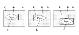
- FIG. 1 is a diagram showing display of moving images by a conventional ultrasonic endoscope system.
- FIG. 2 is a schematic diagram showing the overall configuration of the ultrasonic endoscope system according to this embodiment.
- FIG. 3 is a block diagram illustrating an embodiment of an ultrasound processor device.
- FIG. 4 is a flow chart showing each step of the moving image processing method according to this embodiment.
- FIG. 5 is a diagram showing display of moving images according to the first embodiment.
- FIG. 6 is a diagram showing display of moving images according to the second embodiment.
- FIG. 7 is a diagram showing display of moving images according to the third embodiment.
- FIG. 8 is a diagram showing display of moving images according to the fourth embodiment.
- FIG. 1 is a diagram showing display of moving images by a conventional ultrasonic endoscope system.
- FIG. 1 shows an example in which three medical images I 1 , I 2 , and I 3 , which are time-series frame images of moving images, are sequentially displayed on a monitor.
- position information F 1 indicating the position of the attention region R 1 detected from the medical images I 1 , I 2 , and I 3
- type information T1 indicating the type of the attention area R1
- the position information F1 is a bounding box indicating the range of the attention area R1
- the type information T1 is character information indicating the abbreviation of the organ in the attention area R1 .
- the position information F 1 and the type information T 1 are updated for each frame, and the type information T 1 is always displayed in the center of the position information F 1 .
- an ultrasound processor functioning as a moving image processing apparatus according to the present invention superimposes information of a region of interest included in a medical image on an ultrasound moving image (an example of a medical moving image) to obtain a highly visible image. indicate.
- FIG. 2 is a schematic diagram showing the overall configuration of the ultrasonic endoscope system according to this embodiment.
- an ultrasonic endoscope system 2 (an example of a moving image display system) includes an ultrasonic scope 10, an ultrasonic processor 12 for generating ultrasonic images, and an endoscopic image. It includes an endoscope processor device 14, a light source device 16 that supplies illumination light for illuminating the inside of the body cavity to the ultrasonic scope 10, and a monitor 18 that displays an ultrasonic image and an endoscopic image. .
- the ultrasonic scope 10 (an example of an imaging device) includes an insertion section 20 inserted into a body cavity of a subject, a hand operation section 22 connected to the proximal end of the insertion section 20 and operated by an operator, and a universal cord 24 one end of which is connected to the hand operation unit 22 .
- the other end of the universal cord 24 is connected to an ultrasonic connector 26 connected to the ultrasonic processor device 12 , an endoscope connector 28 connected to the endoscope processor device 14 , and the light source device 16 .
- a light source connector 30 is provided.
- the ultrasound scope 10 is detachably connected to the ultrasound processor device 12, the endoscope processor device 14, and the light source device 16 via these connectors 26, 28, and 30, respectively. Further, the light source connector 30 is connected to an air/water supply tube 32 and a suction tube 34 .
- a monitor 18 receives each video signal generated by the ultrasound processor device 12 and the endoscope processor device 14 and displays an ultrasound image and an endoscopic image.
- the display of the ultrasonic image and the endoscopic image it is possible to display either one of the images on the monitor 18 by appropriately switching between them, or to display both images at the same time.
- the hand operation unit 22 is provided with an air/water supply button 36 and a suction button 38 side by side, as well as a pair of angle knobs 42 and a treatment instrument insertion port 44 .
- the insertion portion 20 has a distal end, a proximal end, and a longitudinal axis 20a, and includes, in order from the distal end side, a distal portion main body 50 made of a hard material, and a bending portion connected to the proximal end side of the distal portion main body 50. 52, and an elongated flexible flexible portion 54 that connects between the base end side of the bending portion 52 and the distal end side of the hand operation portion 22.
- the distal end portion main body 50 is provided on the distal end side of the insertion portion 20 in the direction of the longitudinal axis 20a.
- the bending portion 52 is remotely operated to bend by rotating a pair of angle knobs 42 provided on the hand operation portion 22 . This allows the tip body 50 to be oriented in a desired direction.
- An ultrasonic probe 62 and a bag-shaped balloon 64 covering the ultrasonic probe 62 are attached to the tip body 50 .
- the balloon 64 can be inflated or deflated by being supplied with water from the water supply tank 70 or by sucking the water inside the balloon 64 with the suction pump 72 .
- the balloon 64 is inflated until it abuts against the inner wall of the body cavity in order to prevent attenuation of ultrasonic waves and ultrasonic echoes (echo signals) during ultrasonic observation.
- an endoscope observation section (not shown) having an observation section equipped with an objective lens, an imaging device, and the like, and an illumination section is attached to the distal end body 50 .
- the endoscope observation section is provided behind the ultrasonic probe 62 (on the hand operation section 22 side).
- FIG. 3 is a block diagram showing an embodiment of an ultrasound processor that functions as a moving image processing device according to the present invention.
- the ultrasound processor device 12 shown in FIG. 3 detects a region of interest in the frame image based on the frame images of the moving ultrasound image sequentially acquired, and outputs information indicating the detection result of the region of interest to the moving ultrasound image. It is superimposed and notified to the user.
- the ultrasound processor device 12 includes a transmission/reception unit 100, an image generation unit 102, a CPU (Central Processing Unit) 104, an attention area recognition unit 106, a display position determination unit 108, a display control unit 110, and Includes memory 112 .
- the processes of the transmission/reception unit 100, the image generation unit 102, the CPU (Central Processing Unit) 104, the attention area recognition unit 106, the display position determination unit 108, and the display control unit 110 are realized by at least one processor.
- processors include a CPU (Central Processing Unit), which is a general-purpose processor that executes software (programs) and acts as various functional units, a GPU (Graphics Processing Unit), which is a processor specialized for image processing, A circuit specially designed to execute specific processing such as PLD (Programmable Logic Device), which is a processor whose circuit configuration can be changed after manufacturing such as FPGA (Field Programmable Gate Array), ASIC (Application Specific Integrated Circuit), etc. Also included are dedicated electrical circuits, which are processors with configuration, and the like.
- CPU Central Processing Unit
- GPU Graphics Processing Unit
- PLD Programmable Logic Device
- FPGA Field Programmable Gate Array
- ASIC Application Specific Integrated Circuit
- One processing unit may be composed of one of these various processors, or two or more processors of the same or different type (for example, a plurality of FPGAs, a combination of CPU and FPGA, or a combination of CPU and GPU).
- a plurality of functional units may be configured by one processor.
- a single processor is configured by combining one or more CPUs and software.
- a processor acts as a plurality of functional units.
- SoC System On Chip
- various functional units are configured using one or more of the above various processors as a hardware structure.
- the hardware structure of these various processors is, more specifically, an electrical circuit that combines circuit elements such as semiconductor elements.
- the CPU 104 operates based on various programs including a moving image processing program according to the present invention stored in the memory 112, and includes a transmission/reception unit 100, an image generation unit 102, an attention area recognition unit 106, a display position determination unit 108, and a display position determination unit 108. It centrally controls the display control unit 110 and functions as a part of these units.
- the transmitting/receiving unit 100 and the image generating unit 102 functioning as an ultrasound moving image acquisition processing unit sequentially acquire time-series frame images of ultrasound moving images.
- a transmission unit of the transmission/reception unit 100 generates a plurality of drive signals to be applied to a plurality of ultrasonic transducers of the ultrasonic probe 62 of the ultrasonic scope 10, and based on a transmission delay pattern selected by a scanning control unit (not shown). to apply the plurality of drive signals to the plurality of ultrasonic transducers by giving respective delay times to the plurality of drive signals.
- the receiving unit of the transmitting/receiving unit 100 amplifies a plurality of detection signals respectively output from the plurality of ultrasonic transducers of the ultrasonic probe 62, converts the analog detection signals into digital detection signals (also known as RF (Radio Frequency) data ). This RF data is input to the image generator 102 .
- RF Radio Frequency
- the image generation unit 102 Based on the reception delay pattern selected by the scanning control unit, the image generation unit 102 gives respective delay times to the plurality of detection signals represented by the RF data, and adds the detection signals to obtain a reception focus. process.
- This reception focusing process forms sound ray data in which the focus of the ultrasonic echo is narrowed down.
- the image generation unit 102 further corrects the attenuation due to distance according to the depth of the reflection position of the ultrasonic wave by STC (Sensitivity Timegain Control) for the sound ray data, and then performs envelope detection processing using a low-pass filter or the like.
- Envelope data for one frame, preferably a plurality of frames, is stored in a cine memory (not shown).
- the image generation unit 102 performs preprocessing such as Log (logarithmic) compression or gain adjustment on the envelope data stored in the cine memory to generate a B-mode image.
- the transmission/reception unit 100 and the image generation unit 102 sequentially acquire time-series B-mode images (hereinafter referred to as "medical images").
- the region-of-interest recognizing unit 106 recognizes (detects) a region of interest (an example of an object) included in an input medical image, and stores position information indicating the position of the region of interest in the medical image and a type indicating the type of the region of interest. to obtain information.
- the attention area recognition unit 106 can apply AI (Artificial Intelligence), for example.
- the region of interest in this example is various organs in a medical image (tomographic image of a B-mode image), such as the pancreas, main pancreatic duct, spleen, splenic vein, splenic artery, and gallbladder.
- the position information is, for example, a bounding box that indicates the range of the attention area.
- the position information is not limited to the bounding box, and the attention area may be surrounded by a shape other than a rectangle such as an ellipse, or the attention area may be filled with a color.
- the type information is, for example, character information of at least one of the name and abbreviation of the organ in the region of interest.
- the type information may be a symbol, a figure, a color, or a combination thereof, as long as the user can distinguish the organ in the region of interest.
- the display position determination unit 108 determines a first display position where the position information of the attention area is superimposed on the medical image displayed on the monitor 18 .
- the display position determination unit 108 also determines a second display position where the type information of the attention area is superimposed on the medical image displayed on the monitor 18 .
- the display position determination unit 108 updates the first display position of the sequentially acquired medical images with the first update frequency, and updates the second display position with the second update frequency lower than the first update frequency. Update frequently.
- the display control unit 110 is composed of a first display control unit 110A for displaying the ultrasonic moving image on the monitor 18, which is a display unit, and a second display control unit 110B for displaying information on the attention area on the monitor 18. .
- the first display control unit 110A causes the monitor 18 to sequentially display the medical images sequentially acquired by the transmission/reception unit 100 and the image generation unit 102 .
- a moving image showing an ultrasonic tomographic image is displayed on the monitor 18 .
- the second display control unit 110B superimposes the position information of the region of interest on the medical image displayed on the monitor 18 by the first display control unit 110A at the first position determined by the display position determining unit 108. , the attention area type information is superimposed and displayed at the second position determined by the display position determination unit 108 .
- the memory 112 is at least one memory that stores instructions for execution by the processor.
- Memory 112 stores instructions for the processor to execute.
- the memory 112 includes RAM (Random Access Memory) and ROM (Read Only Memory) (not shown).
- the processor uses the RAM as a work area, executes software using various programs and parameters including a moving image processing program stored in the ROM, and uses the parameters stored in the ROM or the like to generate ultrasound waves.
- Various processes of the processor unit 12 are executed.
- FIG. 4 is a flow chart showing each step of the moving image processing method according to this embodiment.
- the moving image processing method is implemented by CPU 104 executing a moving image processing program stored in memory 112 .
- the moving image processing program may be provided by a computer-readable non-transitory storage medium.
- the ultrasound processor device 12 may read the moving image processing program from the non-temporary storage medium and store it in the memory 112 .
- step ST1 an example of a moving image acquiring process
- the transmitting/receiving unit 100 and the image generating unit 102 sequentially acquire time-series medical images (an example of frame images) of ultrasound moving images.
- step ST2 an example of an object information acquisition process
- the attention area recognizing unit 106 recognizes the position information indicating the position in the medical image of the attention area included in the medical image obtained in step ST1 and the type indicating the type of the attention area.
- step ST3 an example of the display position determination process
- the display position determination unit 108 selects a first display position for displaying the position information acquired in step ST2 and a second display position for displaying the type information acquired in step ST2. determine the position and
- step ST4 an example of the display process
- the first display control unit 110A sequentially displays the medical images sequentially acquired in step ST1 on the monitor 18.
- the second display control unit 110B superimposes the position information acquired in step ST2 on the first display position determined in step ST3 on the medical image displayed on the monitor 18, and displays the position information determined in step ST3.
- the type information acquired in step ST2 is displayed superimposed on the second display position.
- step ST5 the ultrasound processor device 12 determines whether or not to end the display of the ultrasound moving image. When ending, the ultrasound processor device 12 ends the processing of this flowchart. If not, the ultrasound processor 12 returns to the process of step ST1 and repeats the same process.
- step ST3 the display position determination unit 108 updates the first display position with the first update frequency, and updates the second display position with the second display position lower than the first update frequency.
- the update frequency may be controlled according to time, or may be controlled according to the location on the image.
- the display position determining unit 108 updates the first display position of the position information every frame (an example of each frame image) that is the first update frequency, and updates the second display position of the type information.
- the display position is updated every two frames at a second update frequency lower than the first update frequency.
- FIG. 5 is a diagram showing display of moving images according to the first embodiment.
- FIG. 5 shows an example in which four sequentially acquired medical images I 11 , I 12 , I 13 , and I 14 are sequentially displayed on the monitor 18 .
- Position information F 2 of the detected attention area R 2 and type information of the attention area R 2 are displayed on the medical images I 11 , I 12 , and I 13 sequentially displayed on the monitor 18 .
- T2 are superimposed on each other.
- the position information F2 is a bounding box indicating the range of the region of interest R2
- the type information T2 is character information indicating the abbreviation of the organ in the region of interest R2 .
- the region of interest is not shown in the medical image I14.
- medical image I11 is displayed.
- Position information F 2 of the attention area R 2 and type information T 2 of the attention area R 2 are superimposed on the medical image I 11 . It is assumed that both the first display position of the position information F2 and the second display position of the type information T2 are updated at the timing when the medical image I11 is displayed. Therefore, the first display position of the position information F2 and the second display position of the type information T2 of the medical image I11 correspond to the position of the attention region R2 detected in the medical image I11 .
- the second display position of the type information T2 is the center of the position information F2, but the second display position is not limited to this example, and can be determined by the display position determination unit 108 as appropriate.
- the medical image I12 is displayed.
- the position information F 2 of the attention area R 2 and the type information T 2 of the attention area R 2 are superimposed on the medical image I 12 .
- the medical image I12 is displayed at the first display position corresponding to the position of the attention region R2 detected in the medical image I12 .
- Position information F2 is superimposed and displayed.
- the second display position of the type information T2 is updated every two frames, the second display position of the medical image I12 is the same as the second display position of the type information T2 of the medical image I11 . are the same. Therefore, the type information T2 of the medical image I11 is superimposed on the medical image I12 at the same position on the monitor 18 as the type information T2.
- the medical image I13 is displayed. Further, the position information F 2 of the attention area R 2 and the type information T 2 of the attention area R 2 are superimposed on the medical image I 13 . At the timing when the medical image I13 is displayed, both the first display position of the position information F2 and the second display position of the type information T2 are updated. Therefore, the first display position of the position information F2 and the second display position of the type information T2 of the medical image I13 correspond to the position of the attention region R2 detected in the medical image I13 .
- medical image I 14 is displayed. Since the region of interest is not detected from the medical image I14 , the position information F2 is not superimposed on the medical image I14 . Also, since the second display position of the type information T2 is updated every two frames, the timing at which the medical image I14 is displayed is not the update timing of the second display position of the type information T2. However, the second display control unit 110B superimposes the type information T2 only when the position information F2 is superimposed on the medical image. Therefore, the type information T2 is not superimposed on the medical image I14 on which the position information F2 is not superimposed.
- the position information is caused to follow the position of the attention area while the type information is displayed. Visibility can be improved.
- the update frequency of the second display position of the type information is every two frames, but it may be every three frames or more as long as it is lower than the first update frequency of the display position of the position information.
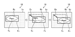
- the display position determining unit 108 updates the first display position of the position information every frame, which is the first update frequency. Further, the display position determination unit 108 updates the second display position when the first display position when the second display position was last updated and the current first display position are separated by a threshold value or more.
- FIG. 6 is a diagram showing display of moving images according to the second embodiment.
- FIG. 6 shows an example in which three sequentially acquired medical images I 21 , I 22 , and I 23 are sequentially displayed on the monitor 18 .
- Positional information F 3 of the detected attention area R 3 and type information of the attention area R 3 are displayed on the medical images I 21 , I 22 , and I 23 sequentially displayed on the monitor 18 . T3 are superimposed on each other. It should be noted that the broken - line frames shown in the medical images I22 and I23 in FIG. not a thing
- the medical image I21 is displayed.
- Position information F 3 of the attention area R 3 and type information T 3 of the attention area R 3 are superimposed on the medical image I 21 . It is assumed that both the first display position of the position information F3 and the second display position of the type information T3 are updated at the timing when the medical image I21 is displayed. Therefore, the first display position of the position information F3 and the second display position of the type information T3 of the medical image I21 correspond to the position of the attention region R3 detected in the medical image I21 .
- Position information F 2 of the attention area R 3 and type information T 2 of the attention area R 3 are superimposed on the medical image I 22 . Since the first display position of the position information F3 is updated for each frame, the medical image I22 displays the first display position corresponding to the position of the attention region R3 detected in the medical image I22 . Position information F3 is superimposed on the position.
- the "first display position when the second display position was last updated" at the time when the medical image I22 was displayed which is the reference display position that serves as the reference for updating the type information T3 is , corresponds to the first display position of the position information F3 superimposed on the medical image I21 .
- the distance between the first display position of the position information F3 superimposed on the medical image I21 and the first display position of the position information F3 superimposed on the medical image I22 is , D1 .
- the distance D 1 has a relationship of D TH >D 1 with respect to the threshold value D TH stored in the memory 112, and the second display position of the type information T 3 of the medical image I 22 is updated. not. Therefore , the type information T3 is superimposed on the medical image I22 at the same position as the type information T3 of the medical image I21 .
- the threshold value DTH may be changed according to the size of the detected attention area on the image (the size of the bounding box) instead of a fixed value.
- Position information F 3 of the attention area R 3 and type information T 3 of the attention area R 3 are superimposed on the medical image I 23 . Since the first display position of the position information F3 is updated for each frame, the medical image I23 is displayed at the first display position corresponding to the position of the attention region R3 detected in the medical image I23 . Position information F3 is superimposed and displayed.
- the reference display position at the time when the medical image I23 is displayed also corresponds to the first display position of the position information F3 superimposed on the medical image I21 .
- the distance between the first display position of the position information F3 superimposed on the medical image I21 and the first display position of the position information F3 superimposed on the medical image I23 is , D2 .
- the second display position of the type information T 3 of the medical image I 23 is updated. Therefore , the type information T3 of the medical image I23 is displayed at the center of the position information F3 .
- the reference display position is the first display position of the position information F3 superimposed on the medical image I23 .
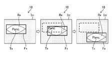
- the display position determining unit 108 updates the first display position of the position information every one frame, which is the first update frequency. Moreover, the display position determining unit 108 updates the second display position when the bounding box when the second display position was last updated and the current bounding box do not overlap.
- FIG. 7 is a diagram showing display of moving images according to the third embodiment.
- FIG. 7 shows an example in which three sequentially acquired medical images I 31 , I 32 , and I 33 are sequentially displayed on the monitor 18 .
- Position information F 4 of the detected attention area R 4 and type information of the attention area R 4 are displayed on the medical images I 31 , I 32 , and I 33 sequentially displayed on the monitor 18 . T4 are superimposed on each other. It should be noted that the broken-line frames shown in the medical images I 32 and I 33 are for explaining the display position of the position information F 4 of the medical image I 31 and are not displayed on the monitor 18. .
- Position information F 4 of the attention area R 4 and type information T 4 of the attention area R 4 are superimposed on the medical image I 32 . Since the first display position of the position information F4 is updated for each frame, the medical image I32 displays the first display position according to the position of the attention region R4 detected in the medical image I32 . Position information F4 is superimposed on the position.
- the reference bounding box that serves as a reference for updating the type information T4 which is the "bounding box when the second display position was last updated" at the time when the medical image I32 was displayed, is the medical image It corresponds to the bounding box of the position information F4 superimposed on I31 .
- the bounding box of the position information F4 superimposed on the medical image I31 and the bounding box of the position information F4 superimposed on the medical image I32 partially overlap. . Therefore, the second display position of the type information T4 of the medical image I32 is not updated, and the type information T4 is displayed superimposed on the medical image I32 at the same position as the type information T4 of the medical image I31 . be done.
- Position information F 4 of the attention area R 4 and type information T 4 of the attention area R 4 are superimposed on the medical image I 33 . Since the first display position of the position information F4 is updated for each frame, the medical image I33 is displayed at the first display position corresponding to the position of the attention region R4 detected in the medical image I33 . Position information F4 is superimposed and displayed.
- the reference bounding box when the medical image I33 is displayed corresponds to the bounding box of the position information F4 superimposed on the medical image I31.
- the bounding box of the position information F4 superimposed on the medical image I31 and the bounding box of the position information F4 superimposed on the medical image I33 are non - overlapping. Therefore, the second display position of the type information T4 of the medical image I33 is updated, and the type information T4 of the medical image I33 is displayed in the center of the position information F4 . Further, for subsequent medical images, the reference bounding box is the bounding box of the position information F4 superimposed on the medical image I33 .
- the third embodiment it is possible to improve the visibility of the type information while allowing the position information to follow the position of the attention area.
- the display position determining unit 108 updates the first display position of the position information every one frame, which is the first update frequency. Further, the display position determining unit 108 updates the second display position when the overlapping area between the bounding box when the second display position was last updated and the current bounding box is equal to or less than the threshold.
- FIG. 8 is a diagram showing display of moving images according to the fourth embodiment.
- FIG. 8 shows an example in which three sequentially acquired medical images I 41 , I 42 , and I 43 are sequentially displayed on the monitor 18 .
- medical image I 41 is displayed.
- Position information F 5 of the attention area R 5 and type information T 5 of the attention area R 5 are superimposed on the medical image I 41 . It is assumed that both the first display position of the position information F5 and the second display position of the type information T5 are updated at the timing when the medical image I41 is displayed. Therefore, the first display position of the position information F5 and the second display position of the type information T5 of the medical image I41 correspond to the position of the attention region R5 detected in the medical image I41 .
- the reference bounding box that serves as a reference for updating the type information T5 and is the "bounding box when the second display position was last updated" at the time when the medical image I42 was displayed is the third 2 corresponds to the bounding box of the position information F5 superimposed on the medical image I41 , as in the embodiment of FIG.
- the bounding box of the positional information F5 superimposed on the medical image I41 and the bounding box of the positional information F5 superimposed on the medical image I42 partially overlap.
- the area of overlap is S1.
- the area S 1 has a relationship of S TH ⁇ S 1 with respect to the threshold value S TH stored in the memory 112, and the second display position of the type information T 5 of the medical image I 42 is updated. not. Therefore, the type information T5 is superimposed on the medical image I42 at the same position as the type information T5 of the medical image I41 .
- the "overlapping area” considered here may be an absolute value on the image or a ratio to the area of the bounding box. Also, the threshold value S TH may be changed according to the size of the detected attention area on the image (the size of the bounding box).
- medical image I 43 is displayed.
- Position information F 5 of the attention area R 5 and type information T 5 of the attention area R 5 are superimposed on the medical image I 43 . Since the first display position of the position information F5 is updated for each frame, the medical image I43 is displayed at the first display position corresponding to the position of the attention region R5 detected in the medical image I43 . Position information F5 is superimposed and displayed.
- the reference bounding box when the medical image I43 is displayed corresponds to the bounding box of the position information F5 superimposed on the medical image I41.
- the bounding box of the positional information F5 superimposed on the medical image I41 and the bounding box of the positional information F5 superimposed on the medical image I43 partially overlap.
- the area of overlap is S2.
- the second display position of the type information T 5 of the medical image I 43 is updated. Therefore, the type information T5 of the medical image I43 is displayed at the center of the position information F5 .
- the reference bounding box is the bounding box of the position information F5 superimposed on the medical image I43 .
- the first display position of position information is updated every frame, but the first update frequency of the first display position of position information is not for each frame image.
- the first update frequency may be determined according to the frequency with which the attention area recognition unit 106 acquires position information. For example, when the attention area recognition unit 106 acquires position information for each of a plurality of frames, the first update frequency may match the acquisition frequency of the position information of the attention area recognition unit 106 .
- an ultrasonic moving image captured by an ultrasonic endoscope has been described as an example, but the present invention can be applied to medical moving images other than ultrasonic moving images. . Also, the present invention can be applied to a moving image of an object.
- Ultrasonic endoscope system 10 Ultrasonic scope 12 Ultrasonic processor device 14 Endoscope processor device 16 Light source device 18 Monitor 20 Insertion section 20a Longitudinal shaft 22 Hand operation section 24 Universal cord 26 Connector for ultrasonic wave 28 Connector for endoscope 30 Connector for light source 32 Tube 34 Tube 36 Air supply/water supply button 38 Suction button 42 Angle knob 44 Treatment instrument insertion port 50 Tip Main body 52 Curved portion 54 Flexible portion 62 Ultrasonic probe 64 Balloon 70 Water supply tank 72 Suction pump 100 Transmission/reception unit 102 Image generation unit 106 Attention area recognition unit 108 Display position determination unit 110 Display control unit 110A First display control unit 110B Second display control unit 112 Memory F1 to F5 Position information I1 to I3 Medical images I11 to I14 Medical images I21 to I13 Medical images I 31 to I 13 .
Landscapes
- Engineering & Computer Science (AREA)
- Health & Medical Sciences (AREA)
- Physics & Mathematics (AREA)
- Theoretical Computer Science (AREA)
- Life Sciences & Earth Sciences (AREA)
- General Physics & Mathematics (AREA)
- Medical Informatics (AREA)
- General Health & Medical Sciences (AREA)
- Multimedia (AREA)
- Nuclear Medicine, Radiotherapy & Molecular Imaging (AREA)
- Public Health (AREA)
- Radiology & Medical Imaging (AREA)
- Surgery (AREA)
- Biophysics (AREA)
- Heart & Thoracic Surgery (AREA)
- Animal Behavior & Ethology (AREA)
- Biomedical Technology (AREA)
- Pathology (AREA)
- Veterinary Medicine (AREA)
- Molecular Biology (AREA)
- Computer Vision & Pattern Recognition (AREA)
- Artificial Intelligence (AREA)
- Computing Systems (AREA)
- Databases & Information Systems (AREA)
- Evolutionary Computation (AREA)
- Software Systems (AREA)
- Epidemiology (AREA)
- Primary Health Care (AREA)
- Computational Linguistics (AREA)
- Ultra Sonic Daignosis Equipment (AREA)
Priority Applications (2)
| Application Number | Priority Date | Filing Date | Title |
|---|---|---|---|
| JP2023518638A JPWO2022234743A1 (https=) | 2021-05-06 | 2022-03-25 | |
| US18/495,790 US12608859B2 (en) | 2021-05-06 | 2023-10-27 | Moving image processing apparatus, moving image processing method and program, and moving image display system for displaying information related to an object in the moving image |
Applications Claiming Priority (2)
| Application Number | Priority Date | Filing Date | Title |
|---|---|---|---|
| JP2021078435 | 2021-05-06 | ||
| JP2021-078435 | 2021-05-06 |
Related Child Applications (1)
| Application Number | Title | Priority Date | Filing Date |
|---|---|---|---|
| US18/495,790 Continuation US12608859B2 (en) | 2021-05-06 | 2023-10-27 | Moving image processing apparatus, moving image processing method and program, and moving image display system for displaying information related to an object in the moving image |
Publications (1)
| Publication Number | Publication Date |
|---|---|
| WO2022234743A1 true WO2022234743A1 (ja) | 2022-11-10 |
Family
ID=83932152
Family Applications (1)
| Application Number | Title | Priority Date | Filing Date |
|---|---|---|---|
| PCT/JP2022/014346 Ceased WO2022234743A1 (ja) | 2021-05-06 | 2022-03-25 | 動画像処理装置、動画像処理方法及びプログラム、動画像表示システム |
Country Status (3)
| Country | Link |
|---|---|
| US (1) | US12608859B2 (https=) |
| JP (1) | JPWO2022234743A1 (https=) |
| WO (1) | WO2022234743A1 (https=) |
Citations (2)
| Publication number | Priority date | Publication date | Assignee | Title |
|---|---|---|---|---|
| WO2020017212A1 (ja) * | 2018-07-20 | 2020-01-23 | 富士フイルム株式会社 | 内視鏡システム |
| JP2020175051A (ja) * | 2019-04-23 | 2020-10-29 | 学校法人慈恵大学 | 診断支援システム、及び診断支援用プログラム |
Family Cites Families (7)
| Publication number | Priority date | Publication date | Assignee | Title |
|---|---|---|---|---|
| CN108024793B (zh) * | 2015-09-25 | 2020-11-17 | 奥林巴斯株式会社 | 超声波观测装置和超声波观测装置的工作方法 |
| JPWO2017104192A1 (ja) | 2015-12-17 | 2017-12-14 | オリンパス株式会社 | 医用観察システム |
| WO2017110459A1 (ja) * | 2015-12-22 | 2017-06-29 | オリンパス株式会社 | 内視鏡用画像処理装置及び内視鏡システム |
| US10292570B2 (en) * | 2016-03-14 | 2019-05-21 | Endochoice, Inc. | System and method for guiding and tracking a region of interest using an endoscope |
| US11937880B2 (en) * | 2017-04-18 | 2024-03-26 | Intuitive Surgical Operations, Inc. | Graphical user interface for monitoring an image-guided procedure |
| CN112654282B (zh) * | 2018-09-11 | 2024-07-12 | 富士胶片株式会社 | 医疗图像处理装置、医疗图像处理方法、内窥镜系统及记录介质 |
| EP4299015A4 (en) * | 2021-02-25 | 2024-08-07 | FUJIFILM Corporation | MEDICAL IMAGE PROCESSING APPARATUS, METHOD AND PROGRAM |
-
2022
- 2022-03-25 JP JP2023518638A patent/JPWO2022234743A1/ja active Pending
- 2022-03-25 WO PCT/JP2022/014346 patent/WO2022234743A1/ja not_active Ceased
-
2023
- 2023-10-27 US US18/495,790 patent/US12608859B2/en active Active
Patent Citations (2)
| Publication number | Priority date | Publication date | Assignee | Title |
|---|---|---|---|---|
| WO2020017212A1 (ja) * | 2018-07-20 | 2020-01-23 | 富士フイルム株式会社 | 内視鏡システム |
| JP2020175051A (ja) * | 2019-04-23 | 2020-10-29 | 学校法人慈恵大学 | 診断支援システム、及び診断支援用プログラム |
Also Published As
| Publication number | Publication date |
|---|---|
| JPWO2022234743A1 (https=) | 2022-11-10 |
| US20240054707A1 (en) | 2024-02-15 |
| US12608859B2 (en) | 2026-04-21 |
Similar Documents
| Publication | Publication Date | Title |
|---|---|---|
| JP5208495B2 (ja) | 医療用システム | |
| US9173632B2 (en) | Ultrasonic diagnosis system and image data display control program | |
| JP4868959B2 (ja) | 体腔内プローブ装置 | |
| US12558068B2 (en) | Medical image processing apparatus, endoscope system, medical image processing method, and medical image processing program | |
| JP4119497B2 (ja) | 超音波画像診断装置 | |
| JP4869197B2 (ja) | 医用ガイド装置 | |
| US12548283B2 (en) | Medical image processing apparatus, method, and program | |
| US20110015523A1 (en) | Ultrasound observation apparatus | |
| JPWO2022202401A5 (https=) | ||
| US20120095341A1 (en) | Ultrasonic image processing apparatus and ultrasonic image processing method | |
| JP7803922B2 (ja) | 機械学習システム、学習方法、学習済みモデル、プログラム及び記録媒体 | |
| JP2010088699A (ja) | 医療画像処理システム | |
| JP2012105966A (ja) | 超音波診断装置、超音波画像処理装置及び超音波画像処理プログラム | |
| JP4869189B2 (ja) | 医用ガイドシステム | |
| JP4098266B2 (ja) | 超音波画像診断装置 | |
| US12608859B2 (en) | Moving image processing apparatus, moving image processing method and program, and moving image display system for displaying information related to an object in the moving image | |
| JP2002315754A (ja) | 細径プローブ型超音波診断装置 | |
| JP2007289720A (ja) | 超音波画像診断装置 | |
| WO2022234742A1 (ja) | 表示処理装置、方法及びプログラム | |
| US20240054645A1 (en) | Medical image processing apparatus, medical image processing method, and program | |
| JP2007268148A (ja) | 超音波診断装置 | |
| EP4338683A1 (en) | Image processing device, image processing system, image processing method, and image processing program | |
| JP2026074293A (ja) | 内視鏡システム及び内視鏡システムの作動方法、プログラム、並びに記録媒体 | |
| US20230419693A1 (en) | Medical image processing apparatus, endoscope system, medical image processing method, and medical image processing program | |
| JP4700405B2 (ja) | 超音波診断装置 |
Legal Events
| Date | Code | Title | Description |
|---|---|---|---|
| 121 | Ep: the epo has been informed by wipo that ep was designated in this application |
Ref document number: 22798850 Country of ref document: EP Kind code of ref document: A1 |
|
| WWE | Wipo information: entry into national phase |
Ref document number: 2023518638 Country of ref document: JP |
|
| NENP | Non-entry into the national phase |
Ref country code: DE |
|
| 122 | Ep: pct application non-entry in european phase |
Ref document number: 22798850 Country of ref document: EP Kind code of ref document: A1 |