WO2022234715A1 - 光反応評価装置 - Google Patents
光反応評価装置 Download PDFInfo
- Publication number
- WO2022234715A1 WO2022234715A1 PCT/JP2022/009626 JP2022009626W WO2022234715A1 WO 2022234715 A1 WO2022234715 A1 WO 2022234715A1 JP 2022009626 W JP2022009626 W JP 2022009626W WO 2022234715 A1 WO2022234715 A1 WO 2022234715A1
- Authority
- WO
- WIPO (PCT)
- Prior art keywords
- light source
- light
- irradiation
- intensity distribution
- sample
- Prior art date
- Legal status (The legal status is an assumption and is not a legal conclusion. Google has not performed a legal analysis and makes no representation as to the accuracy of the status listed.)
- Ceased
Links
Images





Classifications
-
- G—PHYSICS
- G01—MEASURING; TESTING
- G01J—MEASUREMENT OF INTENSITY, VELOCITY, SPECTRAL CONTENT, POLARISATION, PHASE OR PULSE CHARACTERISTICS OF INFRARED, VISIBLE OR ULTRAVIOLET LIGHT; COLORIMETRY; RADIATION PYROMETRY
- G01J3/00—Spectrometry; Spectrophotometry; Monochromators; Measuring colours
- G01J3/28—Investigating the spectrum
- G01J3/42—Absorption spectrometry; Double beam spectrometry; Flicker spectrometry; Reflection spectrometry
-
- G—PHYSICS
- G01—MEASURING; TESTING
- G01J—MEASUREMENT OF INTENSITY, VELOCITY, SPECTRAL CONTENT, POLARISATION, PHASE OR PULSE CHARACTERISTICS OF INFRARED, VISIBLE OR ULTRAVIOLET LIGHT; COLORIMETRY; RADIATION PYROMETRY
- G01J3/00—Spectrometry; Spectrophotometry; Monochromators; Measuring colours
- G01J3/02—Details
- G01J3/10—Arrangements of light sources specially adapted for spectrometry or colorimetry
-
- G—PHYSICS
- G01—MEASURING; TESTING
- G01J—MEASUREMENT OF INTENSITY, VELOCITY, SPECTRAL CONTENT, POLARISATION, PHASE OR PULSE CHARACTERISTICS OF INFRARED, VISIBLE OR ULTRAVIOLET LIGHT; COLORIMETRY; RADIATION PYROMETRY
- G01J3/00—Spectrometry; Spectrophotometry; Monochromators; Measuring colours
- G01J3/28—Investigating the spectrum
- G01J3/443—Emission spectrometry
-
- G—PHYSICS
- G01—MEASURING; TESTING
- G01N—INVESTIGATING OR ANALYSING MATERIALS BY DETERMINING THEIR CHEMICAL OR PHYSICAL PROPERTIES
- G01N21/00—Investigating or analysing materials by the use of optical means, i.e. using sub-millimetre waves, infrared, visible or ultraviolet light
- G01N21/17—Systems in which incident light is modified in accordance with the properties of the material investigated
- G01N21/25—Colour; Spectral properties, i.e. comparison of effect of material on the light at two or more different wavelengths or wavelength bands
- G01N21/255—Details, e.g. use of specially adapted sources, lighting or optical systems
-
- G—PHYSICS
- G01—MEASURING; TESTING
- G01N—INVESTIGATING OR ANALYSING MATERIALS BY DETERMINING THEIR CHEMICAL OR PHYSICAL PROPERTIES
- G01N21/00—Investigating or analysing materials by the use of optical means, i.e. using sub-millimetre waves, infrared, visible or ultraviolet light
- G01N21/17—Systems in which incident light is modified in accordance with the properties of the material investigated
- G01N21/25—Colour; Spectral properties, i.e. comparison of effect of material on the light at two or more different wavelengths or wavelength bands
- G01N21/27—Colour; Spectral properties, i.e. comparison of effect of material on the light at two or more different wavelengths or wavelength bands using photo-electric detection ; circuits for computing concentration
- G01N21/272—Colour; Spectral properties, i.e. comparison of effect of material on the light at two or more different wavelengths or wavelength bands using photo-electric detection ; circuits for computing concentration for following a reaction, e.g. for determining photometrically a reaction rate (photometric cinetic analysis)
-
- G—PHYSICS
- G01—MEASURING; TESTING
- G01N—INVESTIGATING OR ANALYSING MATERIALS BY DETERMINING THEIR CHEMICAL OR PHYSICAL PROPERTIES
- G01N21/00—Investigating or analysing materials by the use of optical means, i.e. using sub-millimetre waves, infrared, visible or ultraviolet light
- G01N21/17—Systems in which incident light is modified in accordance with the properties of the material investigated
- G01N21/25—Colour; Spectral properties, i.e. comparison of effect of material on the light at two or more different wavelengths or wavelength bands
- G01N21/31—Investigating relative effect of material at wavelengths characteristic of specific elements or molecules, e.g. atomic absorption spectrometry
-
- G—PHYSICS
- G01—MEASURING; TESTING
- G01N—INVESTIGATING OR ANALYSING MATERIALS BY DETERMINING THEIR CHEMICAL OR PHYSICAL PROPERTIES
- G01N21/00—Investigating or analysing materials by the use of optical means, i.e. using sub-millimetre waves, infrared, visible or ultraviolet light
- G01N21/62—Systems in which the material investigated is excited whereby it emits light or causes a change in wavelength of the incident light
- G01N21/63—Systems in which the material investigated is excited whereby it emits light or causes a change in wavelength of the incident light optically excited
-
- G—PHYSICS
- G01—MEASURING; TESTING
- G01N—INVESTIGATING OR ANALYSING MATERIALS BY DETERMINING THEIR CHEMICAL OR PHYSICAL PROPERTIES
- G01N21/00—Investigating or analysing materials by the use of optical means, i.e. using sub-millimetre waves, infrared, visible or ultraviolet light
- G01N21/17—Systems in which incident light is modified in accordance with the properties of the material investigated
- G01N21/25—Colour; Spectral properties, i.e. comparison of effect of material on the light at two or more different wavelengths or wavelength bands
- G01N21/31—Investigating relative effect of material at wavelengths characteristic of specific elements or molecules, e.g. atomic absorption spectrometry
- G01N2021/3125—Measuring the absorption by excited molecules
-
- G—PHYSICS
- G01—MEASURING; TESTING
- G01N—INVESTIGATING OR ANALYSING MATERIALS BY DETERMINING THEIR CHEMICAL OR PHYSICAL PROPERTIES
- G01N21/00—Investigating or analysing materials by the use of optical means, i.e. using sub-millimetre waves, infrared, visible or ultraviolet light
- G01N21/62—Systems in which the material investigated is excited whereby it emits light or causes a change in wavelength of the incident light
- G01N21/63—Systems in which the material investigated is excited whereby it emits light or causes a change in wavelength of the incident light optically excited
- G01N21/64—Fluorescence; Phosphorescence
- G01N21/6408—Fluorescence; Phosphorescence with measurement of decay time, time resolved fluorescence
-
- G—PHYSICS
- G01—MEASURING; TESTING
- G01N—INVESTIGATING OR ANALYSING MATERIALS BY DETERMINING THEIR CHEMICAL OR PHYSICAL PROPERTIES
- G01N21/00—Investigating or analysing materials by the use of optical means, i.e. using sub-millimetre waves, infrared, visible or ultraviolet light
- G01N21/62—Systems in which the material investigated is excited whereby it emits light or causes a change in wavelength of the incident light
- G01N21/63—Systems in which the material investigated is excited whereby it emits light or causes a change in wavelength of the incident light optically excited
- G01N21/64—Fluorescence; Phosphorescence
- G01N21/645—Specially adapted constructive features of fluorimeters
Definitions
- the present disclosure relates to a photoreaction evaluation device.
- Quantum yield is used as an evaluation index for photochemical reactions. The quantum yield is expressed by (number of molecules of substance generated in the sample by irradiation with light)/(number of photons absorbed by the sample).
- the excitation light source is referred to herein as the illumination light source.
- the number of photons absorbed by the sample since the number of photons of the light irradiated onto the sample by the irradiation light source (hereinafter referred to as the number of irradiation photons) varies depending on the irradiation light source, it is necessary to calibrate the number of irradiation photons.
- Patent Document 1 describes a method of calibrating the number of irradiated photons using a chemical light meter or an optical power meter.
- the number of irradiated photons changes depending on the wavelength of light. Therefore, it is necessary to calibrate the number of irradiation photons using a chemical photometer according to the wavelength of the light of the irradiation light source. In this case, since the absorption peak by the chemiphotometer is rather broad, it is difficult to accurately measure the number of irradiated photons at each wavelength. Since an optical power meter cannot normally measure the wavelength distribution of light energy, it is difficult to calibrate the correct wavelength distribution of the number of irradiated photons.
- the present invention arranges an irradiation light source, a measuring device, etc., in consideration of the shape of a sample, and uses not only an irradiation light source that generates light having a specific wavelength, but also an irradiation light source that generates light having a wide wavelength range. It is an object of the present invention to provide a photoreaction evaluation device and a method for calculating the number of photons that can accurately calculate the distribution of the number of irradiated photons depending on the wavelength even when used.
- a photoreaction evaluation device is a photoreaction evaluation device that evaluates the photoreaction of a sample placed at a sample position, is arranged to be able to irradiate the sample position with light as irradiation light, and has a white color.
- Irradiation light source that can be exchanged with a standard light source that generates light, a uniform irradiation lens that is attached to the irradiation light source and can irradiate the surface of the sample position with uniform intensity light, and can irradiate the sample position with light
- a spectrophotometer that includes a measurement light source arranged in a sample position and a detection unit arranged to detect the intensity distribution of light from a sample position; The intensity distribution of the light detected by the detection unit in a state in which light is not irradiated by the measurement light source is acquired as a first detection intensity distribution, and the irradiation light source irradiates the sample position where the sample does not exist during the first measurement operation.
- an intensity distribution acquisition unit that acquires, as a second detected intensity distribution, the intensity distribution of light detected by the detection unit in a state where the light is irradiated as the irradiation light and the position of the sample is not irradiated with the light from the measurement light source; radiant intensity for calculating the radiant intensity at each wavelength of the irradiation light of the irradiation light source based on the first detected intensity distribution acquired by the intensity distribution acquisition unit, the second detected intensity distribution acquired by the intensity distribution acquisition unit, and the radiation characteristics of the standard light source a calculation unit, and an irradiation photon number calculation unit that calculates the number of photons at each wavelength of the irradiation light of the irradiation light source as the number of irradiation photons based on the radiation intensity at each wavelength calculated by the radiation intensity calculation unit;
- the light source was arranged on the rear side of the sample position surface irradiated with light from the irradiation light source, and the detection unit was arranged on the
- the wavelength-dependent irradiation photon number distribution can be obtained not only when an irradiation light source that generates light having a specific wavelength is used, but also when an irradiation light source that generates light having a wide wavelength range is used. Accurate calculation becomes possible.
- FIG. 1 is a block diagram showing the configuration of a photoreaction evaluation device according to one embodiment
- FIG. FIG. 2 is a block diagram showing the configuration of a photoreaction evaluation device to be compared
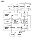
- 2 is a block diagram showing a functional configuration of a data processing unit in FIG. 1
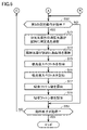
- FIG. FIG. 4 is a flow chart showing a photoreaction evaluation operation of the data processing unit of FIG. 3
- FIG. 4 is a flow chart showing a photoreaction evaluation operation of the data processing unit of FIG. 3
- FIG. FIG. 10 is a diagram for explaining a standard data acquisition operation; It is a figure which shows the example of 1st detection intensity distribution acquired by standard data acquisition operation
- a photoreaction evaluation device and a method for calculating the number of photons according to an embodiment of the present disclosure will be described in detail below with reference to the drawings.
- FIG. 1 is a block diagram showing the configuration of a photoreaction evaluation device according to one embodiment.
- the photoreaction evaluation device 100 of FIG. 1 includes a measuring section 10 and a data processing section 30 .
- a measurement unit 10 includes an irradiation light source 1 , a spectrophotometer 2 and a sample cell 3 .
- a sample S is set in the sample cell 3 .
- the position of the sample cell 3 corresponds to the sample position.
- the evaluation of the photoreaction of the sample S includes the evaluation of the number of absorbed photons in the photochemical reaction of the sample S.
- the irradiation light source 1 irradiates the sample cell 3 with light as excitation light.
- a light source that generates light of a specific wavelength, light of a specific wavelength range, light of multiple wavelengths, or white light can be used.
- the illumination light source 1 may be various light sources such as, for example, LEDs (light emitting diodes), xenon lamps, mercury lamps, or deuterium lamps.
- a uniform irradiation lens 1 a is attached to a portion where light is irradiated from the irradiation light source 1 .
- the uniform irradiation lens 1a is an optical element for irradiating the entire surface of the position of the sample cell 3 with the light emitted from the irradiation light source 1 with uniform intensity.
- any position in the sample cell 3 can be irradiated with light of substantially uniform intensity.
- the uniform irradiation lens 1a may be an optical element capable of irradiating light of uniform intensity, such as a telecentric lens or a rod lens.
- the spectrophotometer 2 includes a measurement light source 21 , a spectroscope (not shown) and a detector 22 .
- a multichannel spectrophotometer using a polychromator can be used.
- FIG. 2 is a block diagram showing the configuration of a photoreaction evaluation device 100A to be compared.
- the photoreaction evaluation device 100A shown in FIG. 2 has the same configuration as the photoreaction evaluation device 100 shown in FIG. Therefore, in the photoreaction evaluation device 100A shown in FIG. 2, the same numbers are assigned to the same configurations as in the photoreaction evaluation device 100 shown in FIG.
- the measurement light from the measurement light source 21 of the spectrophotometer 2 is orthogonal to the irradiation light from the irradiation light source 1 in the sample cell 3A.
- the detector 22 of the spectrophotometer 2 is arranged at a position facing the measurement light source 21 with the sample cell 3A interposed therebetween. Since the sample SA set in the sample cell 3A does not have a wide surface on which light is irradiated, it is not necessary to provide the irradiation light source 1 with the uniform irradiation lens 1a.
- the measurement unit 10 measures the irradiation light source 1 and the measurement light source 21 such that the direction in which light is emitted from the irradiation light source 1 and the direction in which light is emitted from the measurement light source 21 of the spectrophotometer 2 are substantially parallel. are placed. That is, the directions in which light is emitted from the irradiation light source 1 and the measurement light source 21 are substantially perpendicular to the surface of the sample cell 3 (angle ⁇ 90°, angle ⁇ 90°).
- the irradiation light source 1 is provided with a uniform irradiation lens 1a, and the light emitted from the irradiation light source 1 is irradiated to the entire surface at the position of the sample cell 3 as light of uniform intensity. Therefore, since light of uniform intensity is emitted from the irradiation light source 1 at any position within the plane of the sample cell 3, the light from the measurement light source 21 is emitted at any position within the plane of the sample cell 3. can be irradiated and measured by the detection unit 22 of the spectrophotometer 2 . As can be seen from FIG.
- the surface of the sample cell 3 and the irradiation light increase as the distance from the position P of the surface of the sample cell 3 perpendicular to the direction in which light is emitted from the irradiation light source 1 increases in the horizontal direction (vertical direction in the drawing). becomes smaller. Therefore, when the light from the measurement light source 21 is irradiated at a position farther than the position P and the measurement is performed by the detection unit 22 of the spectrophotometer 2, the influence of the irradiation light reflected on the surface of the sample cell 3 is reduced.
- the uniform irradiation lens 1a does not have to irradiate the entire surface at the position of the sample cell 3 with light of uniform intensity.
- Light from the measurement light source 21 may be applied to the portion of the sample cell 3 where the uniform irradiation lens 1a irradiates light of uniform intensity, and the detector 22 of the spectrophotometer 2 may measure the light.
- the detection unit 22 of the spectrophotometer 2 may measure the portion of the sample S irradiated with the irradiation light from the uniform irradiation lens 1a and the measurement light from the measurement light source 21 . If the film-shaped sample S can maintain its shape during measurement, the sample cell 3 is unnecessary, and only the sample S may be provided at the position of the sample cell 3 .
- the arrangement of the measurement unit 10 shown in FIG. It is only required that it be arranged on the front side of the surface of the sample cell 3 that is irradiated with light from the .
- the irradiation light source 1 and the detection unit 22 may be arranged on the same side with the sample cell 3 interposed therebetween, and the irradiation light source 1 and the measurement light source 21 may be arranged on opposite sides with the sample cell 3 interposed therebetween.
- the measurement light source 21 and the detection section 22 are arranged at positions facing each other with the sample cell 3 interposed therebetween. That is, it is preferable that the measurement light source 21 and the detection unit 22 are arranged on a straight line with the sample cell 3 interposed therebetween.
- the angular difference between the direction in which the irradiation light source 1 emits light and the direction in which the measurement light source 21 emits light is within a predetermined range.
- the angle ⁇ 90°, the angle ⁇ 90°, and the angle difference between the direction in which the irradiation light source 1 emits light and the direction in which the measurement light source 21 emits light is 0 (zero).
- the angular difference may be within a predetermined range as long as it does not affect the measurement. If the angle ⁇ 90° and the angle ⁇ 90° as shown in FIG. 1, the direction in which the irradiation light source 1 emits light and the direction in which the measurement light source 21 emits light are parallel.
- the irradiation light source 1, the spectrophotometer 2, and the sample cell 3 of the measurement unit 10 in this way, the number of photons can be measured even if the sample S set in the sample cell 3 is a film sample or a film-shaped sample. be able to.
- the data processing unit 30 includes a CPU (central processing unit) 31, a RAM (random access memory) 32, a ROM (read only memory) 33, an input/output I/F (interface) 34, and a storage device 35.
- CPU 31 , RAM 32 , ROM 33 , input/output I/F 34 and storage device 35 are connected to bus 36 .
- An operation unit 40 and a display unit 50 are connected to the bus 36 of the data processing unit 30 .
- the operation unit 40 includes a keyboard, mouse, etc., and is operated by the user to input various commands and data to the data processing unit 30 .
- the display unit 50 includes a liquid crystal display, an organic EL (electroluminescence) display, or the like, and displays various data or the like.
- the storage device 35 includes a storage medium such as a semiconductor memory or memory card, and stores a photoreaction evaluation program.
- the RAM 32 is used as a work area for the CPU 31 .
- a system program is stored in the ROM 33 .
- the CPU 31 controls the irradiation light source 1 and the spectrophotometer 2 through the input/output I/F 34 by executing the photoreaction evaluation program stored in the storage device 35 on the RAM 32, and inputs the output signal of the spectrophotometer 2. It is received through the output I/F 34 .
- the photoreaction evaluation method includes a photon number calculation method.
- the photoreaction evaluation apparatus 100 performs a standard data acquisition operation using the standard light source 1S (FIG. 3), a first measurement operation using the irradiation light source 1, and a second measurement operation for measuring the sample S, which will be described later. do.
- FIG. 3 is a block diagram showing the functional configuration of the data processing unit 30 in FIG.
- the data processing unit 30 includes an intensity distribution acquisition unit 310, a storage unit 320, a radiation intensity calculation unit 330, an irradiation photon number calculation unit 340, an operation control unit 350, an absorbance spectrum acquisition unit 360, an absorption photon number A calculator 370 and a display controller 380 are included.
- the functions of the components (310 to 380) described above are realized by the CPU 31 of FIG.
- a part or all of the components of the data processing unit 30 may be realized by hardware such as an electronic circuit.
- a standard light source 1S indicated by a dashed line in FIG. 3 is attached to the measurement unit 10 (FIG. 1) instead of the irradiation light source 1.
- the standard light source 1S is a light source that generates light having a wavelength range equal to or greater than the wavelength range of the light generated by the irradiation light source 1.
- FIG. A white light source is used as the standard light source 1S.
- the white light source is, for example, an LED that produces white light, although other white light sources may be used.
- the standard light source 1S is a light source that generates light with a wide wavelength range.
- the radiation intensity distribution at all wavelengths of the light generated by the standard light source 1S will be referred to as the radiation characteristic of the standard light source 1S.
- the radiation characteristic includes the radiation intensity at each wavelength of the light generated by the standard light source 1S.
- the radiation characteristics of the standard light source 1S are accurately measured in advance. Since the spectrophotometer 2 has a wavelength sensitivity distribution characteristic that depends on the wavelength, normally the radiant intensity distribution of the light generated by the standard light source 1S and the intensity distribution of the light from the standard light source 1S detected by the spectrophotometer 2 is different.
- the intensity distribution acquisition unit 310 acquires the intensity distribution of light detected by the detection unit 22 of the spectrophotometer 2 as the first detected intensity distribution during the standard data acquisition operation.
- the first detected intensity distribution is the intensity distribution of light detected at all wavelengths of the white light irradiated to the sample cell 3 by the standard light source 1S.
- the intensity distribution acquisition unit 310 acquires the intensity distribution of light detected by the detection unit 22 of the spectrophotometer 2 as a second detected intensity distribution during the first measurement operation.
- the second detected intensity distribution is the intensity distribution of light detected in the wavelength range of the light irradiated onto the sample cell 3 by the irradiation light source 1 .
- the second detected intensity distribution is the intensity distribution of light detected at all wavelengths. If the illumination light source 1 is a light source that generates light of a specific wavelength or light of a specific wavelength range, the second detected intensity distribution is the intensity distribution of light detected at the specific wavelength or specific wavelength range. be.
- the storage unit 320 stores the first detected intensity distribution acquired by the intensity distribution acquiring unit 310 during standard data acquisition and the second detected intensity distribution acquired by the intensity distribution acquiring unit 310 during the first measurement operation. Further, the storage unit 320 stores in advance the radiation characteristics of the standard light source 1S. Further, the storage unit 320 stores the number of irradiation photons calculated by the number-of-irradiation-photons calculation unit 340 and the number of absorption photons calculated by the number-of-absorption-photons calculation unit 370, which will be described later.
- the radiant intensity calculator 330 calculates, based on the first detected intensity distribution, the second detected intensity distribution, and the radiant intensity at each wavelength of the standard light source 1S stored in the storage unit 320, The radiation intensity at each wavelength of the irradiation light source 1 is calculated. Details of the calculation method will be described later.
- the irradiation photon number calculation unit 340 calculates the number of photons of light irradiated to the sample cell 3 by the irradiation light source 1 (hereinafter referred to as the irradiation photon number) based on the radiation intensity at each wavelength calculated by the radiation intensity calculation unit 330. ) is calculated. Details of the calculation method will be described later.
- the operation control unit 350 controls the operation of each component of the data processing unit 30 in order to execute the standard data acquisition operation, the first measurement operation and the second measurement operation based on the operation of the operation unit 40 by the user. At the same time, it controls the operation of the standard light source 1S, the illumination light source 1, and the measurement light source 21 of the spectrophotometer 2.
- the absorbance spectrum acquisition unit 360 acquires the intensity distribution of light detected by the detection unit 22 of the spectrophotometer 2 as an absorbance spectrum during the second measurement operation.
- the absorbed photon number calculation unit 370 calculates the number of absorbed photons at each wavelength based on the absorbance spectrum acquired by the absorbance spectrum acquisition unit 360 and the irradiation photon number calculated by the irradiation photon number calculation unit 340 . Details of the calculation method will be described later.
- the display control unit 380 acquires the number of irradiation photons calculated by the number calculation unit 340 of irradiation photons, the number of absorption photons calculated by the number calculation unit 370 of absorption photons, and the absorbance spectrum acquisition unit 360.
- the display unit 50 displays the obtained absorbance spectrum.
- FIGS. 4 and 5 are flowcharts showing the photoreaction evaluation operation of the data processing unit 30 of FIG.
- FIG. 6 is a diagram for explaining the standard data acquisition operation.
- FIG. 7 is a diagram showing an example of the first detection intensity distribution acquired by the standard data acquisition operation.
- FIG. 8 is a diagram for explaining the first measurement operation.
- FIG. 9 is a diagram showing an example of the second detection intensity distribution obtained by the first measurement operation.
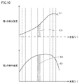
- FIG. 10 is a diagram for explaining a method of calculating the radiant intensity at each wavelength of the irradiation light source 1.
- FIG. 7, 9 and 10 represent the detected intensity at each wavelength detected by the spectrophotometer 2, and the horizontal axis represents the wavelength ⁇ .
- the optical reaction evaluation operation of the optical reaction evaluation device 100 includes the standard data acquisition operation, the first measurement operation and the second measurement operation, as described above.
- the photoreaction evaluation operation in FIGS. 4 and 5 is performed by the CPU 31 in FIG. 3 executing the photoreaction evaluation program.
- the standard data acquisition operation is performed, for example, during installation or maintenance of the photoreaction evaluation device 100.
- the standard data includes the first detected intensity distribution and the radiation characteristics (radiation intensity at each wavelength) of the standard light source 1S.
- the first measurement operation is, for example, routinely performed.
- a second measurement operation is performed when the sample S is measured.
- the operator attaches the standard light source 1S to the operation unit 40 instead of the irradiation light source 1.
- No sample S is set in the sample cell 3 .
- the operation control unit 350 determines whether or not a standard data acquisition operation has been instructed by the operation unit 40 (step S1).
- the operation control section 350 controls the standard light source 1S so that the standard light source 1S irradiates the sample cell 3 with light (step S2).
- the sample cell 3 is irradiated with the light emitted by the standard light source 1S, and the light from the sample cell 3 enters the spectrophotometer 2.
- FIG. 6 the sample cell 3 is irradiated with the light emitted by the standard light source 1S, and the light from the sample cell 3 enters the spectrophotometer 2.
- the sample cell 3 is not irradiated with light from the measurement light source 21 of the spectrophotometer 2 .
- the arrangement of the standard light source 1S, the spectrophotometer 2, and the sample cell 3 shown in FIG. 6 is a schematic arrangement for simplification of explanation, unlike the actual arrangement.
- the intensity distribution acquisition unit 310 acquires the intensity distribution of light detected by the detection unit 22 of the spectrophotometer 2 as a first detected intensity distribution (step S3).
- FIG. 7 shows the relationship between the detected intensity and the wavelength ⁇ as a first detected intensity distribution E1.
- the intensity distribution acquisition unit 310 stores the acquired first detection intensity distribution E1 in the storage unit 320 (step S4). This completes the standard data acquisition operation.
- the operation control section 350 determines whether or not the operation section 40 has instructed the first measurement operation (step S5).
- the operation control section 350 controls the irradiation light source 1 so that the irradiation light source 1 irradiates the sample cell 3 with light (step S6).
- the sample cell 3 is irradiated with the light emitted from the irradiation light source 1, and the light from the sample cell 3 enters the spectrophotometer 2.
- FIG. 1 the spectrophotometer
- the sample cell 3 is not irradiated with light from the measurement light source 21 of the spectrophotometer 2 .
- the arrangement of the irradiation light source 1, the spectrophotometer 2, and the sample cell 3 shown in FIG. 8 is a schematic arrangement for simplification of explanation, unlike the actual arrangement.
- the intensity distribution acquisition unit 310 acquires the intensity distribution of light detected by the detection unit 22 of the spectrophotometer 2 as a second detected intensity distribution (step S7).
- FIG. 9 shows the relationship between the detected intensity and the wavelength ⁇ as a second detected intensity distribution E2.
- the intensity distribution acquisition unit 310 stores the acquired second detection intensity distribution E2 in the storage unit 320 (step S8).
- the radiation intensity calculation unit 330 calculates the radiation at each wavelength of the irradiation light source 1 from the first detection intensity distribution E1 and the second detection intensity distribution E2 stored in the storage unit 320 and the radiation characteristics of the standard light source 1S by the following method.
- the intensity is calculated (step S9).
- each wavelength means a certain wavelength section divided by a specific pitch.
- the first detected intensity distribution E1 is expressed by the following equation.
- the second detected intensity distribution E2 is expressed by the following equation.
- the radiation characteristic Firr of the illumination light source 1 represents the radiation intensity distribution of the light generated by the illumination light source 1 .
- the radiation characteristic Firr contains the radiation intensity of the illumination source 1 at each wavelength.
- Firr (E2/E1) ⁇ Fstd (4)
- the first detected intensity distribution E1 and the radiation characteristic Fstd of the standard light source 1S are known. Therefore, by obtaining the second detected intensity distribution E2 of the irradiation light source 1 using the spectrophotometer 2 capable of detecting the intensity of light at each wavelength, the radiation characteristic of the irradiation light source 1 is obtained from the above equation (4). Firr can be calculated. As a result, the radiant intensity at each wavelength is obtained not only for a light source that emits light of a specific wavelength, but also for a light source that emits light in a specific wavelength range, a light source that emits multi-wavelength light, and a light source that emits white light. be able to.
- the radiation intensity calculator 330 can calculate the radiation intensity at each wavelength of the irradiation light source 1 by the following method.
- the first detected intensity distribution E1 and the second detected intensity distribution E2 are divided into a plurality of wavelength intervals at a constant wavelength pitch.
- the radiation intensity calculator 330 calculates areas under the first detected intensity distribution E1 and the second detected intensity distribution E2 in each wavelength interval.
- the area under the first detection intensity distribution E1 in an arbitrary wavelength section of the first detection intensity distribution E1 is E1i
- the second detection intensity distribution in an arbitrary wavelength section of the second detection intensity distribution E2 Let the area under E2 be E2i. i is a natural number.
- the areas of the plurality of wavelength intervals of the first detected intensity distribution E1 are E11, E12, . . . E1i, .
- the areas of the plurality of wavelength intervals of the second detection intensity distribution E2 are E21, E22, . . . E2i, .
- Fstdi be the radiant intensity of the standard light source 1S in an arbitrary wavelength interval.
- the radiant intensity calculator 330 calculates the radiant intensity Firri of the irradiation light source 1 in an arbitrary wavelength interval from the following equation (step S9).
- Firri (E2i/E1i) ⁇ Fstdi (5)
- the number of irradiated photons Nirr( ⁇ ) at wavelength ⁇ is defined by the following equation from Einstein's energy equation using Planck's constant h, speed of light c, and radiant intensity Firri.
- the wavelength ⁇ corresponds to the i-th wavelength section.
- Nirr( ⁇ ) ( ⁇ /hc) ⁇ Firri (6)
- the irradiation photon number calculation unit 340 calculates the irradiation photon number Nirr( ⁇ ) at each wavelength ⁇ from the above equation (6) using the radiation intensity Firri at each wavelength interval calculated from the above equation (5). (Step S10).
- the irradiation photon number calculation unit 340 causes the storage unit 320 to store the calculated irradiation photon number Nirr( ⁇ ) at each wavelength ⁇ (step S11). This completes the first measurement operation.
- the user sets the sample S in the sample cell 3 of the measurement unit 10 (Fig. 1).
- the operation control section 350 determines whether or not the operation section 40 has instructed the second measurement operation (step S12).
- the operation control unit 350 controls the measurement light source 21 of the spectrophotometer 2 so that it irradiates the sample in the sample cell 3 with light as measurement light (step S13).
- the operation control unit 350 controls the irradiation light source 1 so that the irradiation light source 1 irradiates the sample in the sample cell 3 with light as excitation light (step S14).
- the photons of the excitation light emitted by the irradiation light source 1 are absorbed by the sample S, causing a photochemical reaction.
- the number of photons absorbed depends on the wavelength ⁇ .
- the detector 22 of the spectrophotometer 2 detects the intensity distribution of the light from the sample S.
- the absorbance spectrum acquisition unit 360 acquires the light intensity distribution detected by the detection unit 22 of the spectrophotometer 2 as an absorbance spectrum (step S15). Also, the absorbance spectrum acquisition unit 360 stores the acquired absorbance spectrum in the storage unit 320 (step S16). During the measurement period, the irradiation light source 1 irradiates the sample S with irradiation photon number Nirr( ⁇ ) of excitation light. A photochemical reaction proceeds in accordance with the number of irradiated photons Nirr( ⁇ ). Therefore, the absorbance spectrum acquisition unit 360 acquires the absorbance spectrum, which is time-series data. Let Abs(t, ⁇ ) be the absorbance spectrum at time t. Also, let the number of photons absorbed by the sample S at the wavelength ⁇ at time t be the number of absorbed photons Nabs(t, ⁇ ). The absorbed photon number Nabs(t, ⁇ ) is represented by the following equation.
- Nabs(t, ⁇ ) ⁇ (1 ⁇ 10 ⁇ Abs(t, ⁇ ) ) ⁇ Nirr( ⁇ ) (7)
- ⁇ is a coefficient for correcting the component reflected by the sample cell 3 .
- Absorbed photon number calculation unit 370 calculates the above equation (7 ), the number of absorbed photons Nabs(t, ⁇ ) is calculated (step S17). Also, the absorbed photon number calculation unit 370 stores the calculated absorbed photon number Nabs(t, ⁇ ) in the storage unit 320 (step S18). This completes the second measurement operation.
- the operation control unit 350 determines whether or not an operation end instruction has been given by the operation unit 40 (step S19). When the end of the operation is not instructed, the operation control section 350 returns to step S1. If the standard data acquisition operation is not instructed in step S1, the operation control section 350 proceeds to step S5. If the first measurement operation is not instructed in step S5, the operation control section 350 proceeds to step S12. When the second measurement operation is not instructed in step S12, the operation control section 350 proceeds to step S19. When the end of the operation is instructed in step S19, the operation control section 350 ends the optical reaction evaluation operation.
- the quantum yield in the photochemical reaction can be calculated using the number of molecules (atoms or molecules) of the substance (atoms or molecules) generated by the photochemical reaction in the sample S and the number of absorbed photons calculated by the second measurement operation.
- the number of molecules of the substance produced by the photochemical reaction within the sample S can be obtained, for example, by analyzing the sample S using a gas chromatograph or a liquid chromatograph.
- the first detection intensity distribution E1 obtained using the standard light source 1S that generates white light is different from each wavelength in a wide wavelength range. and the emission characteristic Fstd of the standard light source 1S includes the emission intensity at each wavelength in a wide wavelength range. Therefore, it is possible to accurately calculate the radiation intensity at each wavelength in the wavelength range of the irradiation light from the irradiation light source 1 during the first measurement operation. As a result, the number of irradiation photons at each wavelength in the wavelength range of the irradiation light from the irradiation light source 1 can be calculated accurately.
- the wavelength-dependent distribution of the number of irradiation photons can be accurately obtained not only when the irradiation light source 1 that generates light having a specific wavelength is used, but also when the irradiation light source 1 that generates light having a wide wavelength range is used. It is possible to calculate to
- the wavelength of the irradiation light from the irradiation light source 1 is calculated during the second measurement operation.
- the number of absorbed photons at each wavelength in the range can be accurately calculated.
- the storage unit 320 stores the first detection intensity distribution E1 acquired when acquiring the standard data. Accordingly, it is not necessary to detect the first detected intensity distribution E1 using the standard light source 1S during the first measurement operation. Therefore, the time and effort required for the first measurement operation are reduced.
- a white light source is used as the standard light source 1S
- a light source that generates light of various wavelengths or wavelength ranges can be used as the irradiation light source 1.
- the number of irradiation photons at each wavelength of various irradiation light sources 1 can be accurately calculated. Therefore, it is possible to accurately calculate the number of photons absorbed by the sample S using light of a desired wavelength.
- the position of the sample cell 3 corresponds to the sample position. It may be the position of the holder or the sample support.
- the data processing unit 30 of the photoreaction evaluation device 100 may be configured by a personal computer, may be configured by a mobile electronic terminal such as a smartphone, or may be configured by a server or the like connected to a network.
- a photoreaction evaluation device is a photoreaction evaluation device that evaluates a photoreaction of a sample placed at a sample position, an irradiation light source disposed so as to be able to irradiate the sample position with light as irradiation light, and provided so as to be replaceable with a standard light source that generates white light; a uniform irradiation lens attached to the irradiation light source and capable of irradiating the surface of the sample position with light of uniform intensity; a spectrophotometer including a measurement light source arranged to irradiate the sample position with light, and a detection unit arranged to detect the intensity distribution of the light from the sample position; The intensity distribution of light detected by the detection unit in a state where the sample position where no sample exists is irradiated with light from the standard light source and the sample position is not irradiated with light from the measurement light source is defined as a first detected intensity distribution.
- the detection unit is detected by the detection unit in a state in which the sample position where the sample does not exist is irradiated with light as irradiation light from the irradiation light source and the sample position is not irradiated with light from the measurement light source during the first measurement operation.
- an intensity distribution acquisition unit that acquires the intensity distribution of the detected light as a second detected intensity distribution; Based on the first detected intensity distribution acquired by the intensity distribution acquisition unit, the second detected intensity distribution acquired by the intensity distribution acquisition unit, and the radiation characteristics of the standard light source, each of the irradiation light of the irradiation light source a radiant intensity calculator that calculates radiant intensity at a wavelength; an irradiation photon number calculation unit that calculates the number of photons at each wavelength of the irradiation light of the irradiation light source as the number of irradiation photons based on the radiation intensity at each wavelength calculated by the radiation intensity calculation unit;
- the measurement light source is arranged on the back side of the surface of the sample position irradiated with light from the irradiation light source,
- the detection unit may be arranged on the front side of the surface of the sample position irradiated with light from the irradiation light source.
- the first detection intensity distribution obtained using the standard light source is acquired. Radiation characteristics of standard light sources are known.
- the intensity distribution of light detected by the detector while the position of the sample is irradiated with light from the irradiation light source is acquired as the second detected intensity distribution.
- the radiation intensity at each wavelength of the illumination light from the illumination light source is calculated.
- the number of irradiation photons of the irradiation light source is calculated based on the calculated radiation intensity at each wavelength.
- the first detected intensity distribution obtained using a standard light source producing white light includes the detected intensity at each wavelength over a wide wavelength range, and the radiation characteristic of the standard light source is at each wavelength over a wide wavelength range. Includes radiant intensity. Therefore, during the first measurement operation, it is possible to accurately calculate the radiation intensity at each wavelength in the wavelength range of the irradiation light from the irradiation light source. Thereby, it is possible to accurately calculate the number of irradiation photons at each wavelength in the wavelength range of the irradiation light of the irradiation light source.
- the wavelength-dependent irradiation photon distribution can be accurately calculated not only when an irradiation light source that emits light having a specific wavelength is used, but also when an irradiation light source that emits light having a wide wavelength range is used. It is possible to
- the measurement light source is arranged on the back side of the surface of the sample position irradiated with light from the irradiation light source, and the detection unit is arranged at the position of the sample irradiated with light from the irradiation light source.
- the photoreaction evaluation device described in item 2 since the light from the measurement light source passes through the sample and enters the detection unit, the accuracy of measuring the number of photons is improved.
- a direction in which the irradiation light source emits light may be parallel to a direction in which the measurement light source emits light.
- the light from the irradiation light source is less likely to affect the light from the measurement light source.
- the photoreaction evaluation device according to any one of items 1 to 4, Intensity distribution of light detected by the detection unit in a state in which the sample at the sample position is irradiated with light from the measurement light source and the sample at the sample position is irradiated with light from the irradiation light source during the second measurement operation.
- an absorbance spectrum acquisition unit that acquires as an absorbance spectrum;
- the number of photons absorbed by the sample at each wavelength is calculated based on the number of irradiation photons calculated by the irradiation photon number calculation unit and the absorbance spectrum acquired by the absorbance spectrum acquisition unit.
- An absorbed photon number calculator for calculating the number of photons may be further provided.
- the light intensity distribution detected by the spectrophotometer in a state where the sample at the sample position is irradiated with light from the irradiation light source is the absorbance spectrum.
- the number of absorbed photons is calculated based on the number of irradiated photons and the absorbance spectrum. In this case, the number of irradiation photons at each wavelength in the wavelength range of the irradiation light from the irradiation light source is accurately calculated during the first measurement operation. Therefore, it is possible to accurately calculate the number of absorbed photons at each wavelength in the wavelength range of the irradiation light from the irradiation light source.
- the intensity distribution acquisition unit may further include a storage unit that stores the first detected intensity distribution acquired by the intensity distribution acquisition unit before the first measurement operation and the second measurement operation.
- the unit may obtain the first detection intensity distribution stored in the storage unit during the first measurement operation.
- the first detection intensity distribution acquired before the first measurement operation and the second measurement operation is stored in the storage unit. Accordingly, it is not necessary to detect the first detected intensity distribution using the standard light source during the first measurement operation. Therefore, the time and effort required for the first measurement operation are reduced.
- a light source that emits white light, monochromatic light, or light within a certain wavelength range may be selectively provided as the irradiation light source.
- a light source that generates light of various wavelengths or wavelength ranges can be used as the irradiation light source.
- light of a desired wavelength can be used to accurately evaluate the photoresponse of various samples.
- Intensity distribution acquisition unit 320 storage unit, 330 radiation intensity calculation unit, 340 irradiation photon number calculation unit, 350 operation control unit, 360 absorbance spectrum acquisition unit, 370 absorption photon number calculation unit, 380 display control unit, E1, E2... Detected intensity distribution, S, SA... Samples.
Landscapes
- Physics & Mathematics (AREA)
- Spectroscopy & Molecular Physics (AREA)
- General Physics & Mathematics (AREA)
- Chemical & Material Sciences (AREA)
- Health & Medical Sciences (AREA)
- Pathology (AREA)
- Biochemistry (AREA)
- General Health & Medical Sciences (AREA)
- Life Sciences & Earth Sciences (AREA)
- Immunology (AREA)
- Analytical Chemistry (AREA)
- Chemical Kinetics & Catalysis (AREA)
- Engineering & Computer Science (AREA)
- Mathematical Physics (AREA)
- Theoretical Computer Science (AREA)
- Nuclear Medicine, Radiotherapy & Molecular Imaging (AREA)
- Investigating Or Analysing Materials By Optical Means (AREA)
Priority Applications (3)
| Application Number | Priority Date | Filing Date | Title |
|---|---|---|---|
| US18/558,169 US20240230524A1 (en) | 2021-05-06 | 2022-03-07 | Photoreaction Evaluation Apparatus |
| JP2023518625A JP7639899B2 (ja) | 2021-05-06 | 2022-03-07 | 光反応評価装置 |
| CN202280043794.2A CN117616268A (zh) | 2021-05-06 | 2022-03-07 | 光反应评价装置 |
Applications Claiming Priority (2)
| Application Number | Priority Date | Filing Date | Title |
|---|---|---|---|
| JP2021-078640 | 2021-05-06 | ||
| JP2021078640 | 2021-05-06 |
Publications (1)
| Publication Number | Publication Date |
|---|---|
| WO2022234715A1 true WO2022234715A1 (ja) | 2022-11-10 |
Family
ID=83932049
Family Applications (1)
| Application Number | Title | Priority Date | Filing Date |
|---|---|---|---|
| PCT/JP2022/009626 Ceased WO2022234715A1 (ja) | 2021-05-06 | 2022-03-07 | 光反応評価装置 |
Country Status (4)
| Country | Link |
|---|---|
| US (1) | US20240230524A1 (https=) |
| JP (1) | JP7639899B2 (https=) |
| CN (1) | CN117616268A (https=) |
| WO (1) | WO2022234715A1 (https=) |
Citations (6)
| Publication number | Priority date | Publication date | Assignee | Title |
|---|---|---|---|---|
| JP2002071449A (ja) * | 2000-09-01 | 2002-03-08 | Nippon Hoso Kyokai <Nhk> | フォトン数計数装置および量子効率測定装置 |
| US20040090622A1 (en) * | 2001-05-03 | 2004-05-13 | Nielsen Hans Ole | Apparatus and sensing devices for measuring fluorescence lifetimes of fluorescence sensors |
| JP2014134527A (ja) * | 2013-01-12 | 2014-07-24 | Oh'tec Electronics Corp | Led測定装置の校正方法、及びその方法を用いたled測定装置 |
| JP2019113568A (ja) * | 2019-04-18 | 2019-07-11 | 浜松ホトニクス株式会社 | 分光測定装置および分光測定方法 |
| WO2020022038A1 (ja) * | 2018-07-24 | 2020-01-30 | ソニー株式会社 | 情報処理装置、情報処理方法、情報処理システム、およびプログラム |
| US20210102893A1 (en) * | 2019-10-08 | 2021-04-08 | Halliburton Energy Services, Inc. | Transmissive scattering for radiometry |
Family Cites Families (4)
| Publication number | Priority date | Publication date | Assignee | Title |
|---|---|---|---|---|
| JP5516486B2 (ja) * | 2011-04-14 | 2014-06-11 | 株式会社島津製作所 | 分光測定装置及びプログラム |
| US9482612B2 (en) * | 2014-11-14 | 2016-11-01 | Infinitum Solutions, Inc. | Photon emitter characterization using photoluminescence quenching in nitrogen vacancy color centers |
| JP7056627B2 (ja) * | 2019-05-17 | 2022-04-19 | 横河電機株式会社 | 分光分析装置及び分光分析方法 |
| WO2021166310A1 (ja) | 2020-02-20 | 2021-08-26 | 株式会社島津製作所 | 光反応評価装置およびフォトン数算出方法 |
-
2022
- 2022-03-07 JP JP2023518625A patent/JP7639899B2/ja active Active
- 2022-03-07 US US18/558,169 patent/US20240230524A1/en active Pending
- 2022-03-07 CN CN202280043794.2A patent/CN117616268A/zh active Pending
- 2022-03-07 WO PCT/JP2022/009626 patent/WO2022234715A1/ja not_active Ceased
Patent Citations (6)
| Publication number | Priority date | Publication date | Assignee | Title |
|---|---|---|---|---|
| JP2002071449A (ja) * | 2000-09-01 | 2002-03-08 | Nippon Hoso Kyokai <Nhk> | フォトン数計数装置および量子効率測定装置 |
| US20040090622A1 (en) * | 2001-05-03 | 2004-05-13 | Nielsen Hans Ole | Apparatus and sensing devices for measuring fluorescence lifetimes of fluorescence sensors |
| JP2014134527A (ja) * | 2013-01-12 | 2014-07-24 | Oh'tec Electronics Corp | Led測定装置の校正方法、及びその方法を用いたled測定装置 |
| WO2020022038A1 (ja) * | 2018-07-24 | 2020-01-30 | ソニー株式会社 | 情報処理装置、情報処理方法、情報処理システム、およびプログラム |
| JP2019113568A (ja) * | 2019-04-18 | 2019-07-11 | 浜松ホトニクス株式会社 | 分光測定装置および分光測定方法 |
| US20210102893A1 (en) * | 2019-10-08 | 2021-04-08 | Halliburton Energy Services, Inc. | Transmissive scattering for radiometry |
Also Published As
| Publication number | Publication date |
|---|---|
| US20240230524A1 (en) | 2024-07-11 |
| JPWO2022234715A1 (https=) | 2022-11-10 |
| JP7639899B2 (ja) | 2025-03-05 |
| CN117616268A (zh) | 2024-02-27 |
Similar Documents
| Publication | Publication Date | Title |
|---|---|---|
| JP6075788B2 (ja) | 蛍光および吸収分析のシステムおよび方法 | |
| CN105008898B (zh) | 用于组合的libs和ir吸收光谱法研究的系统和方法 | |
| US10209189B2 (en) | Spectrum measuring device, spectrum measuring method, and specimen container | |
| US20100256924A1 (en) | Method, apparatus, program, and recording medium for evaluating ultraviolet radiation protection effect | |
| CN104981687B (zh) | 分光测定装置及分光测定方法 | |
| TWI653443B (zh) | Light measuring device and light measuring method | |
| KR102802712B1 (ko) | 광학 측정 방법 및 처리 장치 | |
| US11385168B2 (en) | Spectroscopic analysis apparatus, spectroscopic analysis method, and readable medium | |
| JP7315088B2 (ja) | 光反応評価装置およびフォトン数算出方法 | |
| CN111458027B (zh) | 一种紫外光谱的测量方法及装置 | |
| JP7639899B2 (ja) | 光反応評価装置 | |
| JP6061031B2 (ja) | 分光分析システムおよび該方法 | |
| JPWO2018198364A1 (ja) | 分光蛍光光度計、分光測定方法、及び分光蛍光光度計用制御ソフトウェア | |
| CN117881949A (zh) | 分光光度计 | |
| JP2020159867A (ja) | 分光測定装置、および、分光測定プログラム | |
| CN212082600U (zh) | 一种紫外光谱的测量装置 | |
| JP2014224812A (ja) | 成分濃度計測装置と方法 | |
| JP2008070172A (ja) | 分光蛍光光度計及びその補正方法 | |
| CN211374503U (zh) | 光谱检测装置 | |
| Mantena et al. | Diffuse Reflectance Illumination Module Improvements in Near-Infrared Spectrometer for Heterogeneous Sample Analysis | |
| WO2017117320A1 (en) | Apparatus for analysis of irregular surface using electromagnetic energy | |
| Kozlov et al. | Unforeseen Light‐Emitting Diode Aging: Impact on Scientific Equipment, Research Precision, and Reproducibility | |
| JP6248460B2 (ja) | 励起光照射装置 | |
| JP3128163U (ja) | 分光光度計 | |
| Omar et al. | EBT3-based dosimeter in characterizing UVA–LEDs with lambertian radiation pattern |
Legal Events
| Date | Code | Title | Description |
|---|---|---|---|
| 121 | Ep: the epo has been informed by wipo that ep was designated in this application |
Ref document number: 22798822 Country of ref document: EP Kind code of ref document: A1 |
|
| WWE | Wipo information: entry into national phase |
Ref document number: 2023518625 Country of ref document: JP |
|
| NENP | Non-entry into the national phase |
Ref country code: DE |
|
| WWE | Wipo information: entry into national phase |
Ref document number: 202280043794.2 Country of ref document: CN |
|
| WWE | Wipo information: entry into national phase |
Ref document number: 18558169 Country of ref document: US |
|
| 122 | Ep: pct application non-entry in european phase |
Ref document number: 22798822 Country of ref document: EP Kind code of ref document: A1 |