WO2022230702A1 - ガスタービン燃焼器構造体 - Google Patents
ガスタービン燃焼器構造体 Download PDFInfo
- Publication number
- WO2022230702A1 WO2022230702A1 PCT/JP2022/017993 JP2022017993W WO2022230702A1 WO 2022230702 A1 WO2022230702 A1 WO 2022230702A1 JP 2022017993 W JP2022017993 W JP 2022017993W WO 2022230702 A1 WO2022230702 A1 WO 2022230702A1
- Authority
- WO
- WIPO (PCT)
- Prior art keywords
- combustor
- liner
- oxidant
- combustors
- combustion gas
- Prior art date
- Legal status (The legal status is an assumption and is not a legal conclusion. Google has not performed a legal analysis and makes no representation as to the accuracy of the status listed.)
- Ceased
Links
Images






Classifications
-
- F—MECHANICAL ENGINEERING; LIGHTING; HEATING; WEAPONS; BLASTING
- F23—COMBUSTION APPARATUS; COMBUSTION PROCESSES
- F23R—GENERATING COMBUSTION PRODUCTS OF HIGH PRESSURE OR HIGH VELOCITY, e.g. GAS-TURBINE COMBUSTION CHAMBERS
- F23R3/00—Continuous combustion chambers using liquid or gaseous fuel
- F23R3/02—Continuous combustion chambers using liquid or gaseous fuel characterised by the air-flow or gas-flow configuration
- F23R3/04—Air inlet arrangements
- F23R3/10—Air inlet arrangements for primary air
- F23R3/12—Air inlet arrangements for primary air inducing a vortex
-
- F—MECHANICAL ENGINEERING; LIGHTING; HEATING; WEAPONS; BLASTING
- F02—COMBUSTION ENGINES; HOT-GAS OR COMBUSTION-PRODUCT ENGINE PLANTS
- F02C—GAS-TURBINE PLANTS; AIR INTAKES FOR JET-PROPULSION PLANTS; CONTROLLING FUEL SUPPLY IN AIR-BREATHING JET-PROPULSION PLANTS
- F02C3/00—Gas-turbine plants characterised by the use of combustion products as the working fluid
- F02C3/20—Gas-turbine plants characterised by the use of combustion products as the working fluid using a special fuel, oxidant, or dilution fluid to generate the combustion products
-
- F—MECHANICAL ENGINEERING; LIGHTING; HEATING; WEAPONS; BLASTING
- F02—COMBUSTION ENGINES; HOT-GAS OR COMBUSTION-PRODUCT ENGINE PLANTS
- F02C—GAS-TURBINE PLANTS; AIR INTAKES FOR JET-PROPULSION PLANTS; CONTROLLING FUEL SUPPLY IN AIR-BREATHING JET-PROPULSION PLANTS
- F02C3/00—Gas-turbine plants characterised by the use of combustion products as the working fluid
- F02C3/20—Gas-turbine plants characterised by the use of combustion products as the working fluid using a special fuel, oxidant, or dilution fluid to generate the combustion products
- F02C3/30—Adding water, steam or other fluids for influencing combustion, e.g. to obtain cleaner exhaust gases
-
- F—MECHANICAL ENGINEERING; LIGHTING; HEATING; WEAPONS; BLASTING
- F23—COMBUSTION APPARATUS; COMBUSTION PROCESSES
- F23R—GENERATING COMBUSTION PRODUCTS OF HIGH PRESSURE OR HIGH VELOCITY, e.g. GAS-TURBINE COMBUSTION CHAMBERS
- F23R3/00—Continuous combustion chambers using liquid or gaseous fuel
- F23R3/02—Continuous combustion chambers using liquid or gaseous fuel characterised by the air-flow or gas-flow configuration
- F23R3/04—Air inlet arrangements
- F23R3/06—Arrangement of apertures along the flame tube
-
- F—MECHANICAL ENGINEERING; LIGHTING; HEATING; WEAPONS; BLASTING
- F23—COMBUSTION APPARATUS; COMBUSTION PROCESSES
- F23R—GENERATING COMBUSTION PRODUCTS OF HIGH PRESSURE OR HIGH VELOCITY, e.g. GAS-TURBINE COMBUSTION CHAMBERS
- F23R3/00—Continuous combustion chambers using liquid or gaseous fuel
- F23R3/02—Continuous combustion chambers using liquid or gaseous fuel characterised by the air-flow or gas-flow configuration
- F23R3/16—Continuous combustion chambers using liquid or gaseous fuel characterised by the air-flow or gas-flow configuration with devices inside the flame tube or the combustion chamber to influence the air or gas flow
- F23R3/18—Flame stabilising means, e.g. flame holders for after-burners of jet-propulsion plants
- F23R3/20—Flame stabilising means, e.g. flame holders for after-burners of jet-propulsion plants incorporating fuel injection means
-
- F—MECHANICAL ENGINEERING; LIGHTING; HEATING; WEAPONS; BLASTING
- F23—COMBUSTION APPARATUS; COMBUSTION PROCESSES
- F23R—GENERATING COMBUSTION PRODUCTS OF HIGH PRESSURE OR HIGH VELOCITY, e.g. GAS-TURBINE COMBUSTION CHAMBERS
- F23R3/00—Continuous combustion chambers using liquid or gaseous fuel
- F23R3/28—Continuous combustion chambers using liquid or gaseous fuel characterised by the fuel supply
-
- F—MECHANICAL ENGINEERING; LIGHTING; HEATING; WEAPONS; BLASTING
- F23—COMBUSTION APPARATUS; COMBUSTION PROCESSES
- F23R—GENERATING COMBUSTION PRODUCTS OF HIGH PRESSURE OR HIGH VELOCITY, e.g. GAS-TURBINE COMBUSTION CHAMBERS
- F23R3/00—Continuous combustion chambers using liquid or gaseous fuel
- F23R3/28—Continuous combustion chambers using liquid or gaseous fuel characterised by the fuel supply
- F23R3/286—Continuous combustion chambers using liquid or gaseous fuel characterised by the fuel supply having fuel-air premixing devices
-
- F—MECHANICAL ENGINEERING; LIGHTING; HEATING; WEAPONS; BLASTING
- F23—COMBUSTION APPARATUS; COMBUSTION PROCESSES
- F23R—GENERATING COMBUSTION PRODUCTS OF HIGH PRESSURE OR HIGH VELOCITY, e.g. GAS-TURBINE COMBUSTION CHAMBERS
- F23R3/00—Continuous combustion chambers using liquid or gaseous fuel
- F23R3/28—Continuous combustion chambers using liquid or gaseous fuel characterised by the fuel supply
- F23R3/30—Continuous combustion chambers using liquid or gaseous fuel characterised by the fuel supply comprising fuel prevapourising devices
-
- F—MECHANICAL ENGINEERING; LIGHTING; HEATING; WEAPONS; BLASTING
- F23—COMBUSTION APPARATUS; COMBUSTION PROCESSES
- F23R—GENERATING COMBUSTION PRODUCTS OF HIGH PRESSURE OR HIGH VELOCITY, e.g. GAS-TURBINE COMBUSTION CHAMBERS
- F23R3/00—Continuous combustion chambers using liquid or gaseous fuel
- F23R3/42—Continuous combustion chambers using liquid or gaseous fuel characterised by the arrangement or form of the flame tubes or combustion chambers
-
- F—MECHANICAL ENGINEERING; LIGHTING; HEATING; WEAPONS; BLASTING
- F23—COMBUSTION APPARATUS; COMBUSTION PROCESSES
- F23R—GENERATING COMBUSTION PRODUCTS OF HIGH PRESSURE OR HIGH VELOCITY, e.g. GAS-TURBINE COMBUSTION CHAMBERS
- F23R3/00—Continuous combustion chambers using liquid or gaseous fuel
- F23R3/42—Continuous combustion chambers using liquid or gaseous fuel characterised by the arrangement or form of the flame tubes or combustion chambers
- F23R3/46—Combustion chambers comprising an annular arrangement of several essentially tubular flame tubes within a common annular casing or within individual casings
-
- F—MECHANICAL ENGINEERING; LIGHTING; HEATING; WEAPONS; BLASTING
- F23—COMBUSTION APPARATUS; COMBUSTION PROCESSES
- F23R—GENERATING COMBUSTION PRODUCTS OF HIGH PRESSURE OR HIGH VELOCITY, e.g. GAS-TURBINE COMBUSTION CHAMBERS
- F23R3/00—Continuous combustion chambers using liquid or gaseous fuel
- F23R3/42—Continuous combustion chambers using liquid or gaseous fuel characterised by the arrangement or form of the flame tubes or combustion chambers
- F23R3/50—Combustion chambers comprising an annular flame tube within an annular casing
-
- F—MECHANICAL ENGINEERING; LIGHTING; HEATING; WEAPONS; BLASTING
- F23—COMBUSTION APPARATUS; COMBUSTION PROCESSES
- F23R—GENERATING COMBUSTION PRODUCTS OF HIGH PRESSURE OR HIGH VELOCITY, e.g. GAS-TURBINE COMBUSTION CHAMBERS
- F23R2900/00—Special features of, or arrangements for continuous combustion chambers; Combustion processes therefor
- F23R2900/03342—Arrangement of silo-type combustion chambers
Definitions
- Embodiments of the present invention relate to gas turbine combustor structures.
- the combustor is inserted vertically above or below the outer casing. That is, the vertical silo combustor is positioned through the outer and inner casings at a 90 degree angle to the axial direction of the turbine rotor.
- the combustor inlet conditions are very high pressure and high temperature. Under these conditions, when the premixed combustion method is adopted for the combustor of a supercritical CO2 gas turbine, the premixed gas before being injected into the combustion zone self-ignites in the premixed gas supply pipe. There is Therefore, the combustor of the supercritical CO2 gas turbine adopts the diffusion combustion method.
- FIG. 13 is a longitudinal cross-sectional view of a vertical silo-type combustor structure 300 in a supercritical CO 2 gas turbine.
- 14 is a diagram showing the XX section of FIG. 13.
- Combustor structure 300 includes combustor 310 , aft liner 320 and scroll 330 .
- Combustor structure 300 also includes a plurality of combustors 310 .
- the combustor structure 300 is arranged through the outer casing 350 and the inner casing 355 from a direction perpendicular to the axial direction of the turbine rotor 340 .
- a combustor casing 360 surrounding the combustor structure 300 is provided outside the outer casing 350 .
- the other end of combustor casing 360 is closed with head plate 361 .
- a sleeve 351 is provided between an outer casing 350 and an inner casing 355 through which the combustor structure 300 passes.
- the combustor 310 includes a combustor liner 311 , a fuel supply section 312 and an oxidant supply section 313 .
- the combustor liner 311 is composed of a tubular member that burns fuel and oxidant.
- a side wall of the combustor liner 311 is provided with a plurality of introduction holes 311a for guiding the supercritical CO 2 flowing outside the combustor liner 311 to the inside.
- the fuel supply section 312 supplies fuel into the combustor liner 311 .
- the oxidant supply unit 313 supplies oxidant into the combustor liner 311 .
- the oxidant supply section 313 is provided in an annular shape around the fuel supply section 312 .
- An annular outlet 313a of the oxidant supply unit 313 is provided with a swirler 314 that forms a swirl flow of the oxidant in order to stabilize the flame and promote mixing of the fuel and the oxidant.
- the swirling directions of the swirling flows formed by the swirlers 314 of the combustors 310 are set in the same direction.
- each combustor liner 311 of each combustor 310 is fitted into the through hole 322 of the upstream end wall 321 provided at the upstream end of the rear liner 320 .
- Each combustor liner 311 communicates with the interior of the rear liner 320 via a through hole 322 .
- the rear liner 320 is a flow path that gathers the combustion gas discharged from the multiple combustors 310 and guides it to the scroll 330 while rectifying it.
- Rear liner 320 is constructed of a tubular member, as shown in FIG. A side wall of the rear liner 320 is provided with a plurality of introduction holes 323 for guiding the supercritical CO 2 flowing outside the rear liner 320 inside.
- the scroll 330 is a flow path that guides the combustion gas discharged from the rear liner 320 in the axial direction of the turbine rotor 340 and in the circumferential direction of the turbine rotor 340 .
- the scroll 330 has a curved flow path portion 331 that guides the combustion gas discharged from the rear liner 320 in the axial direction of the turbine rotor 340, and a turbine rotor 340 that guides the combustion gas in the axial direction of the turbine rotor 340. and an annular channel portion 332 leading in the circumferential direction of the rotor 340 .
- An outlet 333 of the annular flow path portion 332 faces the first-stage stationary blade 345.
- the fuel supplied to the fuel supply section 312 and the oxidant supplied to the oxidant supply section 313 form a diffusion flame F within the combustor liner 311 and burn.
- the flow of the oxidant into a swirling flow by the swirler 314 By turning the flow of the oxidant into a swirling flow by the swirler 314, the flow of the combustion gas inside the combustor liner 311 also becomes a swirling flow.
- the swirling direction of the swirling flow of the combustion gas in the combustor liner 311 of each combustor 310 is indicated by solid arrows. As shown in FIG. 14, the swirling direction of the combustion gas in each combustor liner 311 is the same. Note that supercritical CO 2 as a cooling medium is introduced into combustor liner 311 through introduction hole 311 a of combustor liner 311 .
- the combustion gas (including supercritical CO 2 ) discharged from each combustor liner 311 forms one swirling flow in the rear liner 320 and flows through the rear liner 320 .
- the swirling direction of the swirling flow of the combustion gas within the rear liner 320 is indicated by a dashed arrow.
- the swirl direction of the swirl flow in the rear liner 320 is the same as the swirl direction of the combustion gas in the combustor liner 311 .
- the cooling medium, supercritical CO 2 is introduced into the rear liner 320 through the introduction holes 323 of the rear liner 320 .
- the swirling flow of combustion gases (including supercritical CO 2 ) in aft liner 320 enters scroll 330 .
- the combustion gas that has flowed into the curved passage portion 331 of the scroll 330 is deflected by approximately 90 degrees in the axial direction of the turbine rotor 340 .
- the deflected combustion gas then flows into the annular flow path portion 332 .
- the combustion gas that has flowed into the annular flow path portion 332 spreads in the circumferential direction of the turbine rotor 340 .
- the combustion gas is jetted from the outlet 333 of the scroll 330 toward the first-stage stationary blades 345 .
- the swirling flow of combustion gas discharged from the combustor 310 forms one swirling flow within the rear liner 320 . This swirling flow then flows inside the scroll 330 .
- the problem to be solved by the present invention is to jet the combustion gas from the scroll outlet to the first-stage stator vanes at a substantially uniform velocity in the circumferential direction even when a swirling flow of the combustion gas is formed in the combustor. It is another object of the present invention to provide a gas turbine combustor structure capable of
- the gas turbine combustor structure of the embodiment is arranged to penetrate the casing of the gas turbine in a direction perpendicular to the axial direction of the turbine rotor of the gas turbine.
- This gas turbine combustor structure is composed of a plurality of combustors and a tubular body provided downstream of the plurality of combustors in a direction perpendicular to the axial direction of the turbine rotor. a rear liner that collects exhausted combustion gas and guides it downstream; and a rear liner that is connected to the downstream end of the rear liner and guides the combustion gas that is exhausted from the rear liner in the axial direction of the turbine rotor. and a scroll leading in the circumferential direction.
- Each combustor includes a cylindrical combustor liner for combusting fuel and an oxidant, a fuel supply section provided at an upstream end of the combustor liner for supplying fuel into the combustor liner, and the fuel supply.
- an oxidant supply unit that is annularly provided around the combustor liner and that supplies a swirling flow of oxidant into the combustor liner.
- the plurality of combustors are composed of the combustor in which the swirl direction of the swirl flow of the oxidant is clockwise, and the downstream side of the oxidant supply section. and the combustor in which the swirl direction of the swirl flow of the oxidant is counterclockwise when viewed from above.
- FIG. 1 is a system diagram of gas turbine equipment provided with a combustor structure according to a first embodiment
- FIG. It is a figure which shows the longitudinal section of the combustor structure of 1st Embodiment.
- FIG. 3 is a diagram showing a cross section taken along line AA of FIG. 2;
- FIG. 3 is a view showing a BB cross section of FIG. 2;
- FIG. 4 is a diagram schematically showing swirling flows of combustion gas within a closed curve in two adjacent combustors of the combustor structure of the first embodiment;
- FIG. 14 is a diagram showing the pressure distribution of the main flow of combustion gas in the annular flow path portion of the scroll of the combustor structure of the first embodiment and the combustor structure of the comparative example shown in FIG.
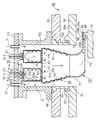
- FIG. 6 is a view showing a longitudinal section of a combustor structure according to a second embodiment
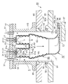
- FIG. 6 is a view showing a longitudinal section of a combustor structure of a third embodiment
- It is a figure which shows the longitudinal cross-section of the combustor structure of 4th Embodiment.
- FIG. 10 is a view showing a CC cross section of FIG. 9
- FIG. 11 is a view showing a longitudinal section of a combustor structure having another configuration according to the fourth embodiment
- FIG. 11 is a view showing a longitudinal section of a combustor structure of a fifth embodiment
- 1 shows a longitudinal section of a vertical silo-type combustor structure in a supercritical CO 2 gas turbine
- FIG. FIG. 14 is a view showing the XX section of FIG. 13;
- FIG. 1 is a system diagram of gas turbine equipment 8 having a combustor structure 1 according to the first embodiment.
- the gas turbine equipment 8 includes a combustor structure 1, a fuel supply system 10, an oxygen supply system 20, a carbon dioxide circulation system 30, a turbine 40, a generator 41, and a heat exchange system. and a vessel 42 .
- the combustor structure 1 functions as a gas turbine combustor structure.
- the fuel supply system 10 supplies fuel to the combustor structure 1 .
- the fuel supply system 10 has a pipe 11 .
- This piping 11 is provided between a fuel supply source (not shown) and the combustor structure 1 . Further, the pipe 11 is provided with a flow control valve 12 for adjusting the flow rate of fuel.
- hydrocarbons such as methane and natural gas are used as fuel.
- fuel for example, coal gasification gas fuel containing carbon monoxide and hydrogen can be used.
- the oxygen supply system 20 supplies oxygen to the combustor structure 1.
- the oxygen supply system 20 has a pipe 21 .
- This pipe 21 is provided between an air separation device (not shown) that separates oxygen from the atmosphere and the combustor structure 1 .
- the pipe 21 is equipped with a flow control valve 22 that regulates the flow rate of oxygen. Further, the pipe 21 is equipped with a compressor 23 that pressurizes oxygen.
- the flow control valve 22 is provided between the compressor 23 and the heat exchanger 42 .
- the pipe 21 extends to the combustor structure 1 through the heat exchanger 42 . Since the flow control valve 22 is provided upstream of the heat exchanger 42 , high-temperature oxygen does not flow through the flow control valve 22 .
- Oxygen separated from the atmosphere by an air separator flows through the pipe 21 .
- the oxygen flowing through the pipe 21 is heated by passing through the heat exchanger 42 and supplied to the combustor structure 1 .
- the carbon dioxide circulation system 30 circulates part of the combustion gas discharged from the turbine 40 to the combustor structure 1 .
- the carbon dioxide circulation system 30 has a pipe 31 . This piping 31 is provided between the outlet of the turbine 40 and the combustor structure 1 .
- the piping 31 is equipped with a condenser 32 that removes water vapor contained in the combustion gas.
- the water vapor in the combustion gas passes through the condenser 32 and is condensed into water. Water is discharged to the outside through, for example, a pipe 36 .
- the piping 31 is equipped with a compressor 33 that pressurizes the combustion gas from which water vapor has been removed in the condenser 32 to a critical pressure or higher.
- the condenser 32 and the compressor 33 are provided in the piping 31 in the region through which the combustion gas cooled by the heat exchanger 42 flows.
- the equivalence ratio here is an equivalence ratio calculated based on the fuel flow rate and the oxygen flow rate. In other words, it is the equivalence ratio (equivalence ratio in the overall) when it is assumed that the fuel and oxygen are uniformly mixed.
- the component of the combustion gas (dry combustion gas) from which water vapor has been removed in the condenser 32 is mostly carbon dioxide. Therefore, the combustion gas from which water vapor has been removed is simply referred to as carbon dioxide.
- the medium circulated through the combustor structure 1 is carbon dioxide.
- the combustion gas from which water vapor has been removed may contain, for example, a trace amount of carbon monoxide of 0.2% or less. called.
- carbon dioxide pressurized to a critical pressure or higher by the compressor 33 becomes a supercritical fluid.
- the piping 31 is arranged so as to pass through the heat exchanger 42 twice. That is, the pipe 31 passes through the heat exchanger 42 once between the turbine 40 and the condenser 32 . The pipe 31 then passes through the heat exchanger 42 again between the compressor 33 and the combustor structure 1 .
- the combustion gas discharged from the turbine 40 is cooled by passing through the heat exchanger 42. At this time, heat radiation from the combustion gas heats the oxygen flowing through the pipe 21 and the carbon dioxide circulating to the combustor structure 1 through the pipe 31 .
- the pipe 31 branches between the compressor 33 and the heat exchanger 42 .
- a pipe 34 branched from the pipe 31 is provided with a flow control valve 35 for adjusting the flow rate of carbon dioxide to be discharged to the outside.
- the carbon dioxide discharged to the outside can be used, for example, in EOR (Enhanced Oil Recovery) employed at oil extraction sites.
- one end side (combustor structure 1 side) of the pipe 11 for supplying fuel is branched into a plurality of branches.
- Each branched pipe 11 is connected to each combustor 50 of the combustor structure 1 .
- One end side (the combustor structure 1 side) of the pipe 31 for circulating the carbon dioxide to the combustor structure 1 is, for example, branched into a plurality.
- Supercritical CO 2 supplied from a part of the branched pipe 31 is used to form an oxidant, which is a mixture of supercritical CO 2 and oxygen.
- the remaining branched pipe 31 is used to introduce supercritical CO 2 around the combustor structure 1 as a cooling medium, as shown in FIG. 2, which will be described later.
- One end side (the combustor structure 1 side) of the pipe 21 that supplies oxygen to the combustor structure 1 is branched into a plurality of branches.
- One branched pipe 31 and one branched pipe 21 are connected to the oxidizer supply section 53 of each combustor 50 . Then, the oxygen introduced into the oxidant supply section 53 and the supercritical CO 2 are mixed to form a mixture. This air-fuel mixture is jetted into the combustor liner 51 as an oxidant.
- the method of forming the air-fuel mixture is not limited to this method.
- a mixing chamber made of a housing member having a space inside may be provided.
- some of the branched pipes 31 and 21 are connected to the mixing chamber.
- the air-fuel mixture formed in the mixing chamber is supplied to the oxidant supply section 53 of each combustor 50 through a pipe.
- the pipe 31 may be branched between the heat exchanger 42 and the combustor structure 1, and the branched pipe may be connected to the pipe 21 through which oxygen flows.
- This connecting portion is provided, for example, in the pipe 21 between the heat exchanger 42 and the combustor structure 1 .
- the pipe 31 may be branched between the compressor 33 and the heat exchanger 42, and the branched pipe may be connected to the pipe 21 through which oxygen flows.
- This connecting portion is provided, for example, in the pipe 21 between the flow control valve 22 and the heat exchanger 42 .
- the pipe branched from the pipe 31 is provided with a flow control valve for adjusting the flow of supercritical CO 2 mixed with oxygen.
- the turbine 40 is rotated by combustion gas discharged from the combustor structure 1 .
- a generator 41 is connected to the turbine 40 .
- FIG. 2 is a view showing a longitudinal section of the combustor structure 1 of the first embodiment.
- FIG. 3 is a diagram showing a cross section along line AA of FIG.
- FIG. 4 is a diagram showing a BB section of FIG. 2 to 4 are cross-sectional views of the combustor structure 1 installed in a gas turbine. Therefore, FIGS. 2 to 4 also show the configuration of, for example, the casing of the gas turbine. 2 and 3 show the configuration of the upper half. Here, an example in which the combustor structure 1 is provided on the upper half side is shown.
- the combustor structure 1 is installed in a supercritical CO2 gas turbine that uses supercritical CO2 as the working fluid. Since the combustor structure 1 and the turbine 40 are operated under extremely high pressure conditions, the casing 80 has a double casing structure including an inner casing 90 and an outer casing 85, as shown in FIGS. be done.
- the outer casing 85 is provided on the outer peripheral side of the inner casing 90 with a predetermined gap.
- stationary blades 95 and moving blades 96 are alternately arranged in the axial direction of the turbine rotor 97 .
- the stationary blade 95 is arranged between the inner ring side wall 95a and the outer ring side wall 95b.
- the rotor blades 96 are provided on rotor wheels 98 of a turbine rotor 97 .
- An outer wall 95c is provided on the outer periphery of the moving blade 96 with a gap from the tip of the moving blade 96. As shown in FIG.
- the outer wall 95c may be configured by extending the outer ring side wall 95b in the axial direction of the turbine rotor 97, for example.
- the combustor structure 1 includes a combustor 50, a rear liner 60, and a scroll 70.
- the combustor structure 1 also includes a plurality of combustors 50 .
- the number of combustors 50 to be arranged is determined, for example, based on the amount of heat that can be supplied from one combustor 50 and the amount of heat required for the supercritical CO 2 gas turbine.
- the combustor structure 1 is arranged through the outer casing 85 and the inner casing 90 from a direction perpendicular to the axial direction of the turbine rotor 97, as shown in FIGS.
- the combustor structure 1 is a so-called vertical silo type combustor structure.
- an example of penetrating the combustor structure 1 from vertically above is shown.
- a combustor casing 110 surrounding the combustor structure 1 is provided outside the outer casing 85 .
- Combustor casing 110 is configured as a cylindrical casing that is open at both ends.
- One end of the combustor casing 110 is fixed to the outer casing 85 .
- the other end of combustor casing 110 is closed with head plate 111 .
- the head plate 111 is provided with through holes (not shown) for drawing the pipes 21 , 31 , and 11 into the combustor casing 110 .
- the outer casing 85 and the inner casing 90 are formed with through holes 86 and 91 through which the combustor structure 1 is passed.
- a sleeve 100 is provided between an outer casing 85 and an inner casing 90 through which the combustor structure 1 passes.
- the sleeve 100 prevents supercritical CO 2 as a cooling medium flowing around the combustor structure 1 from flowing out into the space between the outer casing 85 and the inner casing 90 .
- the sleeve 100 is composed of, for example, a cylindrical member.
- annular protrusion 92 is formed around the sleeve 100 with a gap from the sleeve 100 .
- the ridge portion 92 protrudes toward the outer casing 85 side.
- An annular seal ring 93 is fitted between the sleeve 100 and the ridge portion 92 .
- the combustor 50 includes a combustor liner 51 , a fuel supply section 52 and an oxidant supply section 53 .
- the combustor liner 51 is composed of a cylindrical member that burns fuel and oxidant. One end (upstream end) of the combustor liner 51 is closed with an upstream end wall 51a, and the other end (downstream end) is open.
- the combustor liner 51 is composed of, for example, a cylindrical body extending linearly. Note that the combustor liner 51 may be configured by, for example, a partially curved tubular body.
- the upstream end wall 51 a has an opening 51 b for providing the fuel supply portion 52 and the oxidant supply portion 53 .
- upstream means upstream in the direction in which the combustion gas flows
- downstream means downstream in the direction in which the combustion gas flows
- the combustor liner 51 is arranged such that the central axis of the combustor liner 51 is perpendicular to the axial direction of the turbine rotor 97, for example.
- the side wall of the combustor liner 51 is provided with a plurality of introduction holes 51c for guiding the supercritical CO 2 flowing outside the combustor liner 51 to the inside.
- the supercritical CO 2 flowing outside the combustor liner 51 has the function of cooling the combustor liner 51 .
- the introduction hole 51c is configured by, for example, a slit or a hole.
- Combustor liner 51 is cooled, for example, by film cooling.
- film cooling is applied, supercritical CO 2 as a cooling medium introduced from the introduction hole 51c forms a gaseous heat insulating film between the inner wall surface of the combustor liner 51 and the combustion gas. This prevents the inner wall surface of the combustor liner 51 from directly contacting the combustion gas.
- the fuel supply unit 52 supplies fuel into the combustor liner 51 .
- the fuel supply portion 52 is provided on the upstream end wall 51 a of the combustor liner 51 .
- the fuel supply portion 52 is provided at the center of the upstream end wall 51a.
- the fuel supply unit 52 is configured by, for example, a circular tube.
- the fuel supply unit 52 is connected to the pipe 11 for supplying fuel.
- the outlet 52a of the fuel supply section 52 functions as, for example, a fuel nozzle.
- the outlet 52a is composed of, for example, a single-hole fuel injection hole or a multi-hole fuel injection hole.
- the fuel is jetted into the combustor liner 51 from the outlet 52 a of the fuel supply section 52 .
- the oxidant supply unit 53 supplies the oxidant into the combustor liner 51 .
- the oxidizer supply portion 53 is provided on the upstream end wall 51 a of the combustor liner 51 .
- the oxidant supply section 53 is provided around the fuel supply section 52 concentrically with the fuel supply section 52 and in an annular shape.
- the annular oxidant supply section 53 is configured by, for example, providing a circular tube on the outer periphery of the fuel supply section 52 .
- the fuel supply section 52 and the oxidant supply section 53 are configured with a double pipe structure.
- the fuel is ejected from a central fuel ejection hole, and the oxidant is ejected from an annular channel formed around the central fuel ejection hole. That is, the combustor 50 employs a diffusion combustion method.
- the annular outlet 53a of the oxidant supply unit 53 is provided with, for example, a swirler 55 that forms a swirling flow of the oxidant.
- the swirler 55 has a plurality of blades circumferentially arranged in an annular passage. The vanes are arranged at a predetermined angle with respect to the axial direction of the annular passage.
- a swirl flow having a circumferential velocity component is ejected into the combustor liner 51 .
- mixing of the fuel and the oxidant is promoted in the combustor liner 51, and a stable flame is formed.
- the plurality of combustors 50 are arranged at equal intervals on a predetermined circumference, for example.
- 4 is a cross-sectional view of the combustor 50 viewed from the downstream side of the combustor liner 51.
- the predetermined circumference is, for example, a circumference centered on the central axis of the combustor casing 110 or a circumference centered on the center of the opening (circular opening) at the upstream end of the rear liner 60 .
- the swirl direction of the swirl flow of the oxidant supplied from the oxidant supply unit 53 is clockwise.
- the combustor 50 in which the swirling direction of the swirling flow of the oxidant is clockwise when viewed from the downstream side of the oxidant supply unit 53 is referred to as the oxidant-clockwise combustor 50
- the oxidant-counterclockwise combustor 50 the combustor 50 in which the swirling direction of the swirling flow of the oxygen is counterclockwise.
- the multiple combustors 50 are configured with an even number of combustors 50 .
- the arrangement configuration shown in FIG. 4 is configured such that the swirling directions of the swirling flow of the oxidant in the combustors 50 adjacent in the circumferential direction are opposite to each other. That is, the oxidant-clockwise combustors 50 and the oxidant-counterclockwise combustors 50 are alternately arranged in the circumferential direction.
- the flow of combustion gas in the combustor liner 51 depends on the swirling direction of the oxidant. That is, the flow of the combustion gas in the combustor liner 51 becomes a swirling flow in the same swirling direction as the swirling direction of the swirling flow of the oxidant.
- each combustor 50 in the rear liner 60 an even number of combustors 50 should be provided, half of which are oxidizer-clockwise combustors 50. , and the remaining half of the oxidizer-counterclockwise combustor 50 is preferred.
- the swirler 55 provided in the oxidant supply section 53 of each combustor 50 have the same specifications such as the size and outlet angle.
- the number of oxidizer-clockwise combustors 50 and the number of oxidizer-counterclockwise combustors 50 to be installed may be arbitrarily set.
- each of the oxidant-clockwise combustor 50 and the oxidant-counterclockwise combustor 50 is included.
- the ratio of the circumferential velocity component to the axial velocity component in the swirl flow of the oxidant in the combustor 50 may be increased.
- the swirler 55 may be designed such that the clockwise and counterclockwise swirl flows interfere in the flow field of the combustion gas within the rear liner 60, canceling out each other's circumferential velocity components. preferable.
- FIG. 4 shows an example in which the oxidizer-clockwise combustors 50 and the oxidizer-counterclockwise combustors 50 are alternately arranged in the circumferential direction.
- each combustor 50 is arranged circumferentially. may be placed consecutively.
- FIG. 4 shows an example in which a plurality of combustors 50 are arranged at equal intervals on a predetermined circumference, but the arrangement is not limited to this.
- the multiple combustors 50 may be configured in multiple rows. For example, when arranging six combustors 50, three combustors 50 may be arranged in a straight line and arranged in two rows.
- one combustor 50 described above includes one combustor liner 51 and one fuel-oxidizer supply mechanism 54 provided at the upstream end of this one combustor liner 51 . Then, as shown in FIG. 2, one diffusion flame F is formed on the downstream side of one fuel-oxidant supply mechanism 54 .
- one fuel-oxidizer supply mechanism 54 may include a plurality of fuel supply units 52 and a plurality of oxidizer supply units 53 .
- the swirl directions of the swirl flows supplied from the respective oxidant supply units 53 are set in the same direction.
- each combustor liner 51 of each combustor 50 communicates with the inside of the rear liner 60 via a through hole 63 .
- each combustor 50 is connected to the branched pipe 11 respectively.
- the oxidant supply unit 53 of each combustor 50 is connected to, for example, the branched pipes 21 and 31 respectively.
- oxygen and supercritical CO 2 introduced in the upstream portion of the oxidant supply section 53 are mixed while flowing through the oxidant supply section 53, and oxygen and supercritical CO 2 are mixed at the outlet 53a of the oxidant supply section 53.
- the rear liner 60 is provided downstream of the multiple combustors 50, as shown in FIG.
- the rear liner 60 is a flow path that gathers combustion gas discharged from the plurality of combustors 50 and directs it to the scroll 70 while rectifying it.
- the rear liner 60 is, for example, composed of a tubular member extending in a direction perpendicular to the axial direction of the turbine rotor 97, as shown in FIGS. Further, the rear liner 60 has, for example, a channel portion in which the channel cross-sectional area gradually decreases toward the downstream side. Note that the shape of the rear liner 60 is not limited to this.
- One end (upstream end) of the rear liner 60 is closed with a flat upstream end wall 61, and the other end (downstream end) is open.
- the upstream end wall 61 has a plurality of through holes 63 communicating with the downstream end of each combustor liner 51 as described above. This through-hole 63 is formed in accordance with the position of the downstream end of each combustor liner 51 .
- the other end (downstream end) of the rear liner 60 is connected to the upstream end of the scroll 70 .
- a side wall of the rear liner 60 is provided with a plurality of introduction holes 62 for guiding the supercritical CO 2 flowing outside the rear liner 60 inside.
- the supercritical CO 2 flowing outside this rear liner 60 has the function of cooling the rear liner 60 .
- the configuration of the introduction hole 62 is the same as the configuration of the introduction hole 51c described above. Further, the effect of providing the introduction hole 62 is the same as the effect of providing the introduction hole 51c described above.
- the scroll 70 is a flow path that guides the combustion gas discharged from the rear liner 60 in the axial direction of the turbine rotor 97 and in the circumferential direction of the turbine rotor 97 .
- the scroll 70 includes a curved flow path portion 71 that guides the combustion gas discharged from the rear liner 60 in the axial direction of the turbine rotor 97 and a combustion flow path portion that guides the combustion gas in the axial direction of the turbine rotor 97 . and an annular flow path portion 72 that guides the gas in the circumferential direction of the turbine rotor 97 .
- the upstream end of the curved channel portion 71 is connected to the downstream end of the rear liner 60 .
- the bent flow path portion 71 is composed of a bent pipe that bends about 90 degrees in the axial direction of the turbine rotor 97 .
- the outlet side of the curved flow path portion 71 has a configuration that widens in the circumferential direction of the turbine rotor 97 while being curved.
- the bent channel portion 71 deflects the flow of the combustion gas discharged from the rear liner 60 by approximately 90 degrees. The deflected flow of combustion gas flows in the axial direction of the turbine rotor 97 .
- the annular flow path portion 72 is composed of an annular tube provided to cover the circumference of the turbine rotor 97 . Note that the annular flow path portion 72 is configured, for example, by combining split structures composed of a semi-annular upper half portion and a lower half portion.
- the annular flow path portion 72 widens the flow of combustion gas discharged from the curved flow path portion 71 in the circumferential direction of the turbine rotor 97 .
- the combustion gas having velocity components in the axial direction of the turbine rotor 97 spreads uniformly in the circumferential direction of the turbine rotor 97 .
- the outlet 73 of the annular flow path portion 72 faces the first-stage stationary blade 95.
- the combustion gas flowing through the annular flow path portion 72 is jetted out from the outlet 73 toward the first-stage stationary blade 95 .
- the outlet end of the annular flow path portion 72 is in contact with the upstream ends of the inner ring side wall 95a and the outer ring side wall 95b. As a result, the combustion gas ejected from the outlet 73 is guided to the first stage stationary blade 95 .
- fuel is supplied to the combustor 50 of the combustor structure 1 through the pipe 11 .
- Oxygen separated from the atmosphere is supplied to combustor 50 through piping 21 .
- the oxygen is pressurized to a predetermined pressure by the compressor 23 .
- the pressurized oxygen is heated by passing through heat exchanger 42 .
- circulating supercritical CO 2 is supplied to the combustor structure 1 and combustor 50 through piping 31 . At this time, the supercritical CO 2 is heated by passing through the heat exchanger 42 .
- the oxygen and supercritical CO 2 supplied to the combustor 50 are mixed and ejected as an oxidant into the combustion area within the combustor liner 51 .
- the fuel and oxidant guided to the combustor 50 of the combustor structure 1 are combusted in the combustor liner 51 to become combustion gas. Since the operation of the combustor structure 1 will be described later, a detailed description thereof will be omitted here.
- the combustion gas discharged from the combustor structure 1 is introduced into the turbine 40 .
- Turbine 40 is rotated by combustion gases.
- the generator 41 is driven by the rotation of the turbine 40 to generate electricity.
- the combustion gas discharged from the combustor structure 1 here contains combustion products produced by fuel and oxygen and carbon dioxide circulating in the combustor structure 1 .
- the combustion gas discharged from the turbine 40 is guided to the piping 31 and cooled by passing through the heat exchanger 42 .
- the oxygen flowing through the pipe 21 and the carbon dioxide flowing through the pipe 31 and circulating to the combustor structure 1 are heated by heat radiation from the combustion gas.
- the combustion gas that has passed through the heat exchanger 42 passes through the condenser 32 .
- water vapor contained in the combustion gas is removed.
- Water vapor in the combustion gas is condensed into water by passing through the condenser 32 .
- Water is discharged to the outside through, for example, a pipe 36 .
- Carbon dioxide is pressurized by a compressor 33 intervening in pipe 31 to become supercritical CO 2 .
- Part of the carbon dioxide pressurized by the compressor 33 flows through the piping 31 and is circulated to the combustor structure 1 .
- the supercritical CO 2 is heated to about 700° C., for example, by passing through the heat exchanger 42 .
- the rest of the carbon dioxide pressurized by the compressor 33 is introduced into the pipe 34 branching from the pipe 31 .
- the carbon dioxide introduced into the pipe 34 has its flow rate adjusted by the flow control valve 35 and is discharged to the outside.
- FIG. 1 the action of the combustor structure 1 will be described with reference to FIGS. 2 and 3.
- FIG. 2 the action of the combustor structure 1 will be described with reference to FIGS. 2 and 3.
- combustors 50 are arranged on a predetermined circle at regular intervals, and oxidant-clockwise combustors 50 and oxidant-counterclockwise combustors 50 are arranged around the circle. A case where they are arranged alternately in the direction will be described as an example.
- the fuel supplied from the pipe 11 to the fuel supply section 52 is jetted into the combustor liner 51 from the outlet 52a.
- the oxygen supplied from the pipe 21 to the oxidant supply unit 53 and the supercritical CO 2 supplied from the pipe 31 to the oxidant supply unit 53 are mixed in the oxidant supply unit 53, and are discharged into the combustor liner 51 from the outlet 53a. is ejected to. At this time, a swirling flow is formed by the supercritical CO 2 passing through the swirler 55 provided at the outlet 53a.
- the mixture of fuel and oxidant in the combustor liner 51 is ignited by an ignition device (not shown) and combustion begins.
- An ignition device is provided in each combustor 50 .
- each combustor 50 the swirling flow of the oxidant promotes mixing of the fuel and the oxidant.
- the swirling flow of the oxidant forms a recirculation zone in the combustion zone to form a stable flame.
- the flow of combustion gas in the combustor liner 51 becomes a swirling flow in the same swirling direction as the swirling direction of the swirling flow of the oxidant. That is, when viewed in the circumferential direction, a swirling flow of combustion gas with swirling directions alternately opposite to each other is discharged from the combustor liner 51 to the rear liner 60 .
- the combustion reaction is completed within the combustor liner 51. Therefore, the combustion gas discharged from the outlet of the combustor liner 51 does not contain oxygen and fuel, and is composed mostly of carbon dioxide and water vapor.
- the supercritical CO 2 supplied to the periphery of the combustor structure 1 from the pipe 31 passes through the introduction hole 51c of the combustor liner 51 and is introduced into the combustor liner 51 as a cooling medium.
- the supercritical CO 2 introduced into the combustor liner 51 is discharged from the outlet of the combustor liner 51 together with the combustion gas and flows into the rear liner 60 .
- Combustion gases (including supercritical CO 2 ) discharged from combustor liner 51 of each combustor 50 flow in aft liner 60 toward scroll 70 .
- the supercritical CO 2 supplied from the pipe 31 to the periphery of the combustor structure 1 passes through the introduction hole 62 of the rear liner 60 and is introduced into the rear liner 60 as a cooling medium.
- Supercritical CO 2 introduced into aft liner 60 flows into scroll 70 with the combustion gases.
- the combustion gas (including supercritical CO 2 ) that has flowed into the curved passage portion 71 of the scroll 70 is deflected by approximately 90 degrees in the axial direction of the turbine rotor 97 .
- the deflected combustion gas flows into the annular flow path portion 72 .
- the combustion gas that has flowed into the annular flow path portion 72 spreads in the circumferential direction of the turbine rotor 97 .
- the flow of combustion gas flowing into the scroll 70 is a flow that has almost no circumferential velocity component. Therefore, the flow that spreads from the curved channel portion 71 to the annular channel portion 72 spreads uniformly in the left-right direction (clockwise direction and counterclockwise direction) of the annular channel portion 72 in the cross section shown in FIG. 3, for example. As a result, the combustion gas flow has a substantially uniform velocity distribution within the annular flow path of the annular flow path portion 72 surrounding the turbine rotor 97 .
- the combustion gas is jetted from the outlet 73 of the scroll 70 toward the first stage stationary blade 95 .
- the combustion gas is jetted out from the annular outlet at a substantially uniform velocity in the circumferential direction.
- the combustion gas that has flowed through the combustor structure 1 is guided to the turbine 40 to operate the turbine 40 .
- the circulation ⁇ (circulation) around the closed curve S the value obtained by line-integrating the velocity component Vs in the direction along this closed curve for the entire circumference of this closed curve.
- Circulation ⁇ is defined by the following equation (1).
- combustors 50 in which the swirling direction of the swirling flow of the combustion gas is counterclockwise are alternately arranged in the circumferential direction.
- combustion gas-clockwise combustor 50 in which the swirling direction of the swirling flow of the combustion gas is clockwise when viewed from the downstream side of the combustor 50
- combustion gas-counterclockwise combustor 50 in which the swirling direction of the flow is counterclockwise
- combustion gas-counterclockwise combustor 50 means the oxidant-counterclockwise combustor 50.
- the same combustor 50 is meant.
- FIG. 5 is a diagram schematically showing swirling flows of combustion gas within a closed curve in two adjacent combustors 50 of the combustor structure 1 of the first embodiment.
- the two combustors 50 one is a combustion gas-clockwise combustor 50 and the other is a combustion gas-counterclockwise combustor 50 .
- arrows indicate the swirling direction of the swirling flow of the combustion gas.
- FIG. 5 comprises a closed curve S1 consisting of ABCD and a closed curve S2 consisting of B'-ADC'.
- the sum of cyclic ⁇ for these closed curves S1 and S2 is given by the following equation (2).
- Equation (2) the sum of the circulations ⁇ indicated by Equation (2) is "0".
- the sum of circulation ⁇ is "0" as a whole. becomes.
- FIG. 6 shows the pressure distribution of the main stream of combustion gas in the annular passage portion of the scroll in the combustor structure 1 of the first embodiment and the combustor structure 300 as the comparative example shown in FIG. It is a figure which shows.
- the result of the CFD analysis shown in FIG. 6 is the pressure distribution inside the annular flow path at the position corresponding to the cross section AA in FIG. Further, the results of the CFD analysis show the results at the center of the annular flow path portion 72 along the counterclockwise and clockwise directions about the central axis P of the turbine rotor 97 from the upper half upper central position Q.
- the upper half upper central position Q is the central position in the annular flow path portion 72 vertically above the central axis P of the turbine rotor 97, as shown in FIG.
- the definition of the upper half upper center position Q is the same for the annular flow path portion 332 of the combustor structure 300 of the comparative example.
- the combustion gas-clockwise combustors 50 and the combustion gas-counterclockwise combustors 50 are alternately arranged in the circumferential direction in the arrangement shown in FIG.
- CFD analysis was performed with the specifications.
- CFD analysis was performed under rated operating conditions in the gas turbine equipment 8 .
- the vertical axis in FIG. 6 is the static pressure of the mainstream of the combustion gas flowing through the annular flow path.
- the horizontal axis in FIG. 6 is the circumferential position of the annular flow path portion.
- the central position Q of the upper half upper portion of the annular channel portion in FIG. 3 is 0 degrees.
- the position 90 degrees counterclockwise about the central axis P of the turbine rotor 97 from the upper half upper center position Q is defined as 90 degrees, and the position 90 degrees clockwise from the upper half upper center position Q. is -90 degrees.
- the pressure distribution on the counterclockwise side of the upper half upper center position Q and the pressure distribution on the clockwise side of the upper half upper center position Q It is different from the pressure distribution on the turning side. That is, the pressure distribution of the combustion gas flowing into the annular flow path portion 332 from the curved flow path portion 331 becomes uneven in the circumferential direction.
- the pressure distribution on the counterclockwise side of the upper half upper center position Q and the pressure distribution on the clockwise side of the upper half upper center position Q shows almost the same distribution as the pressure distribution on the side. That is, the pressure distribution of the combustion gas flowing from the curved channel portion 71 into the annular channel portion 72 becomes uniform in the circumferential direction.
- the combustion gas-clockwise combustor 50 and the combustion gas-counterclockwise combustor 50 are provided as the plurality of combustors 50.
- the clockwise swirling flow and the counterclockwise swirling flow interfere to cancel out the circumferential velocity component.
- annular flow path portion 72 of the scroll 70 a uniform combustion gas velocity distribution in the circumferential direction can be obtained.
- the combustion gas can be ejected from the outlet 73 of the scroll 70 (annular flow path portion 72) to the first-stage stationary blades 95 at a substantially uniform speed over the circumferential direction.
- combustor 50 in the combustor structure 1 of the first embodiment in one space in one combustor liner 51, by ejecting a swirling flow of oxidant from the oxidant supply part 53, Acceleration of mixing of fuel and oxidant and stabilization of flame can be realized.
- FIG. 7 is a view showing a longitudinal section of the combustor structure 2 of the second embodiment.
- the same components as those of the combustor structure 1 of the first embodiment are denoted by the same reference numerals, and overlapping descriptions are omitted or simplified.
- the system diagram of the gas turbine equipment is the same as the system diagram of the gas turbine equipment described in the first embodiment.
- the configuration of the combustor structure 2 of the second embodiment is basically the same as that of the combustor structure 1 of the first embodiment except that the reverse swirl imparting section 120 is provided. Therefore, here, the configuration of the reverse turning imparting section 120 will be mainly described.
- each combustor 50 of the combustor structure 1 has a reverse swirl imparting section 120 at the outlet of the combustor liner 51 .
- the reverse swirl imparting part 120 is arranged, for example, so as to block the outlet of the combustor liner 51 .
- the reverse swirl imparting part 120 is composed of an annular swirler. The structure of the swirler is as described in the first embodiment.
- the reverse swirl imparting section 120 imparts swirl to the combustion gas flow passing through the reverse swirl imparting section 120 in a direction opposite to the swirling direction of the swirling flow of the oxidant. That is, the swirl direction imparted to the flow of combustion gas by the reverse swirl imparting section 120 is opposite to the swirling direction of the swirl flow of the combustion gas on the upstream side of the reverse swirl imparting section 120 .
- the swirling direction of the swirling flow of the oxidant in each combustor 50 is not particularly limited. That is, the swirling direction of the swirling flow of the oxidant in each combustor 50 may be clockwise or counterclockwise.
- the swirler that constitutes the reverse swirl imparting section 120 is designed to eliminate the circumferential velocity component in the swirling flow of the combustion gas flowing into the reverse swirl imparting section 120 .
- the combustion gas passes through the reverse swirl imparting section 120, thereby attenuating the swirling flow of the combustion gas.
- the flow of combustion gas entering the rear liner 60 becomes a flow that has substantially no circumferential velocity component.
- the flow that spreads from the curved flow path section 71 to the annular flow path section 72 spreads uniformly in the left-right direction (clockwise direction and counterclockwise direction) of the annular flow path section 72 in the cross section shown in FIG. 3, for example.
- the combustion gas flow has a substantially uniform velocity distribution within the annular flow path of the annular flow path portion 72 surrounding the turbine rotor 97 .
- the combustion gas can be ejected from the outlet 73 of the scroll 70 (annular flow path portion 72) to the first-stage stationary blades 95 at a substantially uniform speed over the circumferential direction.
- FIG. 8 is a view showing a longitudinal section of the combustor structure 3 of the third embodiment.
- a combustor structure 3 according to the third embodiment has basically the same configuration as the combustor structure 1 according to the first embodiment, except that a CO 2 swirl flow introducing section 130 is provided. Therefore, here, the configuration of the CO 2 swirl flow introduction section 130 will be mainly described.
- each combustor 50 of the combustor structure 3 is provided with an annular CO 2 swirl flow introduction section 130 on the outer circumference of the outlet of the combustor liner 51 .
- the CO 2 swirl flow introduction section 130 swirls supercritical CO 2 as a cooling medium supplied from the pipe 31 into the combustor casing 110 to introduce a swirl flow of the supercritical CO 2 into the rear liner 60 .
- the CO 2 swirling flow introduction section 130 is configured with an annular swirler.
- the swirl direction of the supercritical CO 2 swirl flow introduced into the rear liner 60 from the CO 2 swirl flow introduction part 130 is the swirl direction of the combustion gas discharged from the combustor liner 51 provided with the CO 2 swirl flow introduction part 130 . This is the direction opposite to the swirling direction of the flow.
- the swirling direction of the swirling flow of the oxidant in each combustor 50 is not particularly limited. That is, the swirling direction of the swirling flow of the oxidant in each combustor 50 may be clockwise or counterclockwise.
- the flow rate of supercritical CO 2 introduced into the rear liner 60 from each CO 2 swirl flow introduction part 130 and the ratio of the circumferential velocity component to the axial velocity component in the swirl flow are the combustion exhausted from the combustor liner 51. It is set so as to cancel out the circumferential velocity component of the swirl flow of the gas flow.
- the flow that spreads from the curved flow path section 71 to the annular flow path section 72 spreads uniformly in the left-right direction (clockwise direction and counterclockwise direction) of the annular flow path section 72 in the cross section shown in FIG. 3, for example.
- the combustion gas flow has a substantially uniform velocity distribution within the annular flow path of the annular flow path portion 72 surrounding the turbine rotor 97 .
- the combustion gas can be ejected from the outlet 73 of the scroll 70 (annular flow path portion 72) to the first-stage stationary blades 95 at a substantially uniform speed over the circumferential direction.
- FIG. 9 is a view showing a longitudinal section of the combustor structure 4 of the fourth embodiment.
- FIG. 10 is a diagram showing a CC cross section of FIG.
- a combustor structure 4 according to the fourth embodiment has basically the same configuration as the combustor structure 1 according to the first embodiment, except that a CO 2 swirling flow introducing section 140 is provided. Therefore, here, the configuration of the CO 2 swirl flow introduction section 140 will be mainly described.
- the combustor structure 4 has a CO 2 swirl flow introduction section 140 formed in the rear liner 60 .
- the CO 2 swirl flow introduction part 140 is formed in the circumferential direction of the side wall of the rear liner 60 at a predetermined position in the central axis direction of the rear liner 60 .
- the CO 2 swirling flow introduction part 140 is composed of a plurality of through holes penetrating the rear liner 60 in a direction inclined at a predetermined angle with respect to the direction (radial direction) toward the central axis O of the rear liner 60 .
- the through-holes penetrate the rear liner 60 in a tangential direction to the inner peripheral surface of the rear liner 60, for example.
- Each through-hole which is the CO 2 swirling flow introduction part 140 , ejects supercritical CO 2 as a cooling medium supplied from the pipe 31 into the combustor casing 110 , thereby causing the supercritical CO 2 to flow into the rear liner 60 . Form a swirling flow.
- the swirling direction of the swirling flow of the oxidant in each combustor 50 is set to the same direction. That is, the swirling direction of the swirling flow of the combustion gas discharged from each combustor liner 51 is also the same direction.
- the plurality of through-holes which are the CO 2 swirling flow introduction portions 140 , form a swirling flow of supercritical CO 2 in a direction opposite to the swirling direction of the swirling flow of the combustion gas discharged from each combustor liner 51 .
- arrows indicate the swirling direction of the swirling flow of the combustion gas in the combustor liner 51 of each combustor 50 and the ejection direction of the supercritical CO 2 ejected from the through holes.
- the CO 2 swirl flow introduction part 140 is preferably formed on the inlet side of the rear liner 60 , that is, on the upstream part of the rear liner 60 .
- the CO 2 swirl flow introducing portions 140 may be formed at a plurality of predetermined positions in the central axis direction of the rear liner 60 .
- the CO 2 swirl flow introduction part 140 may be formed in multiple stages in the central axis direction of the rear liner 60 .
- the flow rate of supercritical CO 2 introduced into the rear liner 60 from the CO 2 swirl flow introduction part 140 and the inclination angle of the through hole that is the CO 2 swirl flow introduction part 140 with respect to the direction toward the central axis O are is set so as to cancel out the circumferential velocity component of the swirling flow of the combustion gas formed at .
- a swirling flow swirling in one direction is formed in the rear liner 60 by the combustion gas discharged from each combustor liner 51 .
- a swirling flow of supercritical CO 2 is formed in the rear liner 60 in a direction opposite to the swirling direction of the flow of the combustion gas by the supercritical CO 2 ejected from the through hole, which is the CO 2 swirling flow introducing portion 140 . .
- the swirling flow of combustion gas is then attenuated by the swirling flow of supercritical CO2 . This results in a flow of combustion gas that has substantially no circumferential velocity component while flowing through the rear liner 60 .
- the flow that spreads from the curved flow path section 71 to the annular flow path section 72 spreads uniformly in the left-right direction (clockwise direction and counterclockwise direction) of the annular flow path section 72 in the cross section shown in FIG. 3, for example.
- the combustion gas flow has a substantially uniform velocity distribution within the annular flow path of the annular flow path portion 72 surrounding the turbine rotor 97 .
- the swirl flow of the combustion gas is changed to the supercritical CO 2 swirl flow.
- the combustion gas can be ejected from the outlet 73 of the scroll 70 (annular flow path portion 72) to the first-stage stationary blades 95 at a substantially uniform speed over the circumferential direction.
- the configuration of the CO 2 swirling flow introducing section 140 in the combustor structure 4 of the fourth embodiment is not limited to the configuration described above.
- FIG. 11 is a longitudinal cross-sectional view of another configuration of the combustor structure 4 of the fourth embodiment.
- the CO 2 swirl flow introduction part 140 may be composed of an annular swirler provided on the upstream end wall 61 provided at the upstream end of the rear liner 60 .
- An annular swirler is formed along the outer edge of the upstream end wall 61 in the circumferential direction.
- the swirler which is the CO 2 swirling flow introduction part 140 , ejects the supercritical CO 2 supplied from the pipe 31 into the combustor casing 110 to form a swirling flow of supercritical CO 2 in the rear liner 60 .
- the swirling direction of the flow of combustion gas discharged from each combustor liner 51 is also the same direction.
- the swirling direction of the swirling flow of supercritical CO 2 ejected from the CO 2 swirling flow introducing portion 140 is opposite to the swirling direction of the flow of combustion gas discharged from each combustor liner 51 .
- the flow rate of supercritical CO 2 introduced into the rear liner 60 from the CO 2 swirl flow introduction part 140 and the ratio of the circumferential velocity component to the axial direction velocity component of the swirler constituting the CO 2 swirl flow introduction part 140 are It is set so as to cancel out the circumferential velocity component of the swirling flow of the combustion gas formed within 60 .
- FIG. 12 is a view showing a longitudinal section of the combustor structure 5 of the fifth embodiment.
- the combustor structure 5 of the fifth embodiment has basically the same configuration as the combustor structure 1 of the first embodiment, except that a CO 2 swirling flow introducing section 150 is provided. Therefore, here, the configuration of the CO 2 swirl flow introduction section 150 will be mainly described.
- the combustor structure 5 includes a CO 2 swirl flow introduction section 150 on the upstream end wall 61 provided at the upstream end of the rear liner 60 .
- the CO 2 swirl flow introduction part 150 is composed of an annular swirler provided at the center of the through-hole 63 provided on a predetermined circumference corresponding to each combustor liner 51 .
- the swirler which is the CO 2 swirling flow introduction part 150 , ejects the supercritical CO 2 as the cooling medium supplied from the pipe 31 into the combustor casing 110 , thereby creating a swirling flow of supercritical CO 2 in the rear liner 60 .
- the swirling direction of the swirling flow of the oxidant in each combustor 50 is set to the same direction. That is, the swirling direction of the swirling flow of the combustion gas discharged from each combustor liner 51 is also the same direction.
- the swirling direction of the swirling flow of supercritical CO 2 ejected from the CO 2 swirling flow introducing portion 150 is opposite to the swirling direction of the flow of combustion gas discharged from each combustor liner 51 .
- the flow rate of supercritical CO 2 introduced into the rear liner 60 from the CO 2 swirl flow introduction section 150 and the ratio of the circumferential velocity component to the axial velocity component of the swirler constituting the CO 2 swirl flow introduction section 150 are It is set so as to cancel out the circumferential velocity component of the swirling flow of the combustion gas formed within 60 .
- a swirling flow swirling in one direction is formed in the rear liner 60 by the combustion gas discharged from each combustor liner 51 .
- a swirling flow of supercritical CO 2 is formed in the rear liner 60 in a direction opposite to the swirling direction of the flow of the combustion gas by the supercritical CO 2 ejected from the swirler, which is the CO 2 swirling flow introducing portion 150 .
- This swirling flow of supercritical CO 2 is formed at the swirling central portion of the swirling flow of combustion gas.
- the swirling flow of combustion gas is then attenuated by the swirling flow of supercritical CO2 . This results in a flow of combustion gas that has substantially no circumferential velocity component while flowing through the rear liner 60 .
- the flow that spreads from the curved flow path section 71 to the annular flow path section 72 spreads uniformly in the left-right direction (clockwise direction and counterclockwise direction) of the annular flow path section 72 in the cross section shown in FIG. 3, for example.
- the combustion gas flow has a substantially uniform velocity distribution within the annular flow path of the annular flow path portion 72 surrounding the turbine rotor 97 .
- the swirl flow of the combustion gas is changed to the supercritical CO 2 swirl flow.
- the combustion gas can be ejected from the outlet 73 of the scroll 70 (annular flow path portion 72) to the first-stage stationary blades 95 at a substantially uniform speed over the circumferential direction.
- the combustor structure 3 of the third embodiment when the swirling directions of the swirling flows of the combustion gas discharged from the combustor liners 51 are the same (when the swirling directions of the swirling flows of the oxidizer in the combustors 50 are the same) ), the combustor structure 3 includes the CO 2 swirl flow introduction part 140 in the combustor structure 4 of the fourth embodiment or the CO 2 swirl flow introduction part 150 in the combustor structure 5 of the fifth embodiment. may be further provided.
- the combustor structure 4 of the fourth embodiment may further include the CO 2 swirl flow introduction section 150 in the combustor structure 5 of the fifth embodiment.
- the combustor structures 1, 2, 3, 4, 5 may be provided on the lower half side.
- the combustor structures 1, 2, 3, 4, 5 are arranged to penetrate the outer casing 85 and the inner casing 90, for example, vertically from below.
- the combustor structures 1, 2, 3, 4, 5 may be provided on both the upper half side and the lower half side.
- the combustion gas can be ejected from the scroll outlet to the first-stage stationary blades at a substantially uniform velocity in the circumferential direction. It becomes possible.
- Combustor structure 8... Gas turbine equipment, 10... Fuel supply system, 11, 21, 31, 34, 36... Piping, 12, 22, 35... Flow control valve, 20 ... oxygen supply system, 23, 33 ... compressor, 30 ... carbon dioxide circulation system, 32 ... condenser, 40 ... turbine, 41 ... generator, 42 ... heat exchanger, 50 ... combustor, 51 ...
Landscapes
- Engineering & Computer Science (AREA)
- Chemical & Material Sciences (AREA)
- Combustion & Propulsion (AREA)
- Mechanical Engineering (AREA)
- General Engineering & Computer Science (AREA)
Priority Applications (2)
| Application Number | Priority Date | Filing Date | Title |
|---|---|---|---|
| EP22795615.8A EP4332438A4 (en) | 2021-04-30 | 2022-04-18 | Gas turbine combustor structure |
| US18/464,565 US12111054B2 (en) | 2021-04-30 | 2023-09-11 | Gas turbine combustor structure |
Applications Claiming Priority (2)
| Application Number | Priority Date | Filing Date | Title |
|---|---|---|---|
| JP2021-077479 | 2021-04-30 | ||
| JP2021077479A JP7646441B2 (ja) | 2021-04-30 | 2021-04-30 | ガスタービン燃焼器構造体 |
Related Child Applications (1)
| Application Number | Title | Priority Date | Filing Date |
|---|---|---|---|
| US18/464,565 Continuation US12111054B2 (en) | 2021-04-30 | 2023-09-11 | Gas turbine combustor structure |
Publications (1)
| Publication Number | Publication Date |
|---|---|
| WO2022230702A1 true WO2022230702A1 (ja) | 2022-11-03 |
Family
ID=83847053
Family Applications (1)
| Application Number | Title | Priority Date | Filing Date |
|---|---|---|---|
| PCT/JP2022/017993 Ceased WO2022230702A1 (ja) | 2021-04-30 | 2022-04-18 | ガスタービン燃焼器構造体 |
Country Status (4)
| Country | Link |
|---|---|
| US (1) | US12111054B2 (https=) |
| EP (1) | EP4332438A4 (https=) |
| JP (1) | JP7646441B2 (https=) |
| WO (1) | WO2022230702A1 (https=) |
Cited By (1)
| Publication number | Priority date | Publication date | Assignee | Title |
|---|---|---|---|---|
| US11907098B2 (en) | 2022-04-01 | 2024-02-20 | Rebellions Inc. | Method for measuring performance of neural processing device and device for measuring performance |
Families Citing this family (2)
| Publication number | Priority date | Publication date | Assignee | Title |
|---|---|---|---|---|
| JP7808700B2 (ja) * | 2022-02-23 | 2026-01-29 | ヌオーヴォ・ピニォーネ・テクノロジー・ソチエタ・レスポンサビリタ・リミタータ | オキシ燃料タービンシステム及び酸化剤制御方法 |
| US12281795B1 (en) * | 2024-03-11 | 2025-04-22 | Rtx Corporation | Cluster of swirled mini-mixers for fuel-staged, axially staged combustion |
Citations (3)
| Publication number | Priority date | Publication date | Assignee | Title |
|---|---|---|---|---|
| JPH0522868B2 (https=) | 1983-09-28 | 1993-03-30 | Mitsubishi Jukogyo Kk | |
| JP2014037825A (ja) * | 2012-07-20 | 2014-02-27 | Toshiba Corp | タービン、及び発電システム |
| JP2014215036A (ja) * | 2013-04-26 | 2014-11-17 | アルストム テクノロジー リミテッドALSTOM Technology Ltd | ガスタービンにおける缶型環状燃焼器配列用の缶型燃焼器 |
Family Cites Families (10)
| Publication number | Priority date | Publication date | Assignee | Title |
|---|---|---|---|---|
| JPH04100660U (https=) * | 1991-01-30 | 1992-08-31 | ||
| US6374594B1 (en) * | 2000-07-12 | 2002-04-23 | Power Systems Mfg., Llc | Silo/can-annular low emissions combustor |
| US6691515B2 (en) * | 2002-03-12 | 2004-02-17 | Rolls-Royce Corporation | Dry low combustion system with means for eliminating combustion noise |
| US20050241316A1 (en) * | 2004-04-28 | 2005-11-03 | Honeywell International Inc. | Uniform effusion cooling method for a can combustion chamber |
| US8230688B2 (en) * | 2008-09-29 | 2012-07-31 | Siemens Energy, Inc. | Modular transvane assembly |
| JP6822868B2 (ja) | 2017-02-21 | 2021-01-27 | 三菱重工業株式会社 | 燃焼器及びガスタービン |
| US10989410B2 (en) * | 2019-02-22 | 2021-04-27 | DYC Turbines, LLC | Annular free-vortex combustor |
| US11506384B2 (en) * | 2019-02-22 | 2022-11-22 | Dyc Turbines | Free-vortex combustor |
| US20200271319A1 (en) * | 2019-02-22 | 2020-08-27 | DYC Turbines, LLC | Free-Vortex Combustor |
| JP7335038B2 (ja) * | 2019-11-08 | 2023-08-29 | 東芝エネルギーシステムズ株式会社 | ガスタービン燃焼器構造体 |
-
2021
- 2021-04-30 JP JP2021077479A patent/JP7646441B2/ja active Active
-
2022
- 2022-04-18 EP EP22795615.8A patent/EP4332438A4/en not_active Withdrawn
- 2022-04-18 WO PCT/JP2022/017993 patent/WO2022230702A1/ja not_active Ceased
-
2023
- 2023-09-11 US US18/464,565 patent/US12111054B2/en active Active
Patent Citations (3)
| Publication number | Priority date | Publication date | Assignee | Title |
|---|---|---|---|---|
| JPH0522868B2 (https=) | 1983-09-28 | 1993-03-30 | Mitsubishi Jukogyo Kk | |
| JP2014037825A (ja) * | 2012-07-20 | 2014-02-27 | Toshiba Corp | タービン、及び発電システム |
| JP2014215036A (ja) * | 2013-04-26 | 2014-11-17 | アルストム テクノロジー リミテッドALSTOM Technology Ltd | ガスタービンにおける缶型環状燃焼器配列用の缶型燃焼器 |
Non-Patent Citations (1)
| Title |
|---|
| See also references of EP4332438A4 |
Cited By (2)
| Publication number | Priority date | Publication date | Assignee | Title |
|---|---|---|---|---|
| US11907098B2 (en) | 2022-04-01 | 2024-02-20 | Rebellions Inc. | Method for measuring performance of neural processing device and device for measuring performance |
| US12443509B2 (en) | 2022-04-01 | 2025-10-14 | Rebellions Inc. | Method for measuring performance of neural processing device and device for measuring performance |
Also Published As
| Publication number | Publication date |
|---|---|
| JP7646441B2 (ja) | 2025-03-17 |
| JP2022171082A (ja) | 2022-11-11 |
| EP4332438A1 (en) | 2024-03-06 |
| US20230417413A1 (en) | 2023-12-28 |
| EP4332438A4 (en) | 2025-04-30 |
| US12111054B2 (en) | 2024-10-08 |
Similar Documents
| Publication | Publication Date | Title |
|---|---|---|
| JP7335038B2 (ja) | ガスタービン燃焼器構造体 | |
| CN101220953B (zh) | 燃料灵活的三方向旋转旋流器和其使用方法 | |
| CN102032568B (zh) | 用于含氢燃料的燃烧器及其低氮氧化物(nox)运转方法 | |
| JP5331327B2 (ja) | 三重環状反転スワーラ | |
| CN101201176B (zh) | 用于增强预混合装置中混合的燃料喷射槽式喷嘴和方法 | |
| WO2022230702A1 (ja) | ガスタービン燃焼器構造体 | |
| JP4906689B2 (ja) | バーナ,燃焼装置及び燃焼装置の改造方法 | |
| EP2405201B1 (en) | Injection nozzle for a turbomachine | |
| US10865989B2 (en) | Combustor arrangement having arranged in an upstream to downstream flow sequence a radial swirler, pre-chamber with a convergent portion and a combustion chamber | |
| US20110185703A1 (en) | Gas Turbine Combustor | |
| CN102679399B (zh) | 具有固定火苗用燃料喷嘴的燃气涡轮机燃烧室 | |
| US20120282558A1 (en) | Combustor nozzle and method for supplying fuel to a combustor | |
| US10222067B2 (en) | Combustor for a sequential gas turbine having a deflection unit between first and second combustion chambers | |
| US6755359B2 (en) | Fluid mixing injector and method | |
| US8707704B2 (en) | Method and apparatus for assembling turbine engines | |
| JP2016527439A (ja) | 排気ガス再循環を備えたガスタービンエンジンにおける燃焼及びエミッションを制御するシステム及び方法 | |
| JPH11270852A (ja) | 液体燃料で作動するガスタ―ビンの燃焼室 | |
| JP6879631B2 (ja) | ガスタービン燃焼器 | |
| JP2023001633A (ja) | ガスタービン燃焼器の運転方法 | |
| Asai et al. | Multiple-injection dry low-NOx combustor for hydrogen-rich syngas fuel: testing and evaluation of performance in an IGCC pilot plant | |
| CN103930721A (zh) | 用于燃气涡轮机使用的切向且无火焰的环形燃烧器 | |
| JP2023151988A (ja) | ガスタービン燃焼器構造体 | |
| HK1152556B (en) | LOW NOx COMBUSTOR FOR HYDROGEN-CONTAINING FUEL AND ITS OPERATION |
Legal Events
| Date | Code | Title | Description |
|---|---|---|---|
| 121 | Ep: the epo has been informed by wipo that ep was designated in this application |
Ref document number: 22795615 Country of ref document: EP Kind code of ref document: A1 |
|
| WWE | Wipo information: entry into national phase |
Ref document number: 2022795615 Country of ref document: EP |
|
| ENP | Entry into the national phase |
Ref document number: 2022795615 Country of ref document: EP Effective date: 20231130 |
|
| NENP | Non-entry into the national phase |
Ref country code: DE |
|
| WWW | Wipo information: withdrawn in national office |
Ref document number: 2022795615 Country of ref document: EP |