WO2022230702A1 - ガスタービン燃焼器構造体 - Google Patents
ガスタービン燃焼器構造体 Download PDFInfo
- Publication number
- WO2022230702A1 WO2022230702A1 PCT/JP2022/017993 JP2022017993W WO2022230702A1 WO 2022230702 A1 WO2022230702 A1 WO 2022230702A1 JP 2022017993 W JP2022017993 W JP 2022017993W WO 2022230702 A1 WO2022230702 A1 WO 2022230702A1
- Authority
- WO
- WIPO (PCT)
- Prior art keywords
- combustor
- liner
- oxidant
- combustors
- combustion gas
- Prior art date
Links
- 239000000567 combustion gas Substances 0.000 claims abstract description 158
- 239000007800 oxidant agent Substances 0.000 claims abstract description 106
- 239000000446 fuel Substances 0.000 claims abstract description 82
- 230000001590 oxidative effect Effects 0.000 claims description 94
- 239000007789 gas Substances 0.000 claims description 55
- 238000011144 upstream manufacturing Methods 0.000 claims description 35
- 239000002826 coolant Substances 0.000 claims description 15
- CURLTUGMZLYLDI-UHFFFAOYSA-N Carbon dioxide Chemical compound O=C=O CURLTUGMZLYLDI-UHFFFAOYSA-N 0.000 description 62
- QVGXLLKOCUKJST-UHFFFAOYSA-N atomic oxygen Chemical compound [O] QVGXLLKOCUKJST-UHFFFAOYSA-N 0.000 description 35
- 239000001301 oxygen Substances 0.000 description 35
- 229910052760 oxygen Inorganic materials 0.000 description 35
- 229910002092 carbon dioxide Inorganic materials 0.000 description 31
- 238000002485 combustion reaction Methods 0.000 description 24
- 239000001569 carbon dioxide Substances 0.000 description 21
- XLYOFNOQVPJJNP-UHFFFAOYSA-N water Chemical compound O XLYOFNOQVPJJNP-UHFFFAOYSA-N 0.000 description 14
- 230000004087 circulation Effects 0.000 description 12
- 238000010586 diagram Methods 0.000 description 12
- 238000002156 mixing Methods 0.000 description 9
- 230000000052 comparative effect Effects 0.000 description 8
- 239000000203 mixture Substances 0.000 description 8
- 238000004458 analytical method Methods 0.000 description 7
- 230000002238 attenuated effect Effects 0.000 description 5
- 239000012530 fluid Substances 0.000 description 5
- 238000001816 cooling Methods 0.000 description 4
- 238000009792 diffusion process Methods 0.000 description 4
- 230000000694 effects Effects 0.000 description 4
- VNWKTOKETHGBQD-UHFFFAOYSA-N methane Chemical compound C VNWKTOKETHGBQD-UHFFFAOYSA-N 0.000 description 4
- 230000002093 peripheral effect Effects 0.000 description 4
- 238000009841 combustion method Methods 0.000 description 3
- UGFAIRIUMAVXCW-UHFFFAOYSA-N Carbon monoxide Chemical compound [O+]#[C-] UGFAIRIUMAVXCW-UHFFFAOYSA-N 0.000 description 2
- 229910002091 carbon monoxide Inorganic materials 0.000 description 2
- 238000011156 evaluation Methods 0.000 description 2
- 238000002347 injection Methods 0.000 description 2
- 239000007924 injection Substances 0.000 description 2
- 238000000034 method Methods 0.000 description 2
- 238000012986 modification Methods 0.000 description 2
- 230000004048 modification Effects 0.000 description 2
- 230000000149 penetrating effect Effects 0.000 description 2
- 230000005855 radiation Effects 0.000 description 2
- 239000007787 solid Substances 0.000 description 2
- PCTMTFRHKVHKIS-BMFZQQSSSA-N (1s,3r,4e,6e,8e,10e,12e,14e,16e,18s,19r,20r,21s,25r,27r,30r,31r,33s,35r,37s,38r)-3-[(2r,3s,4s,5s,6r)-4-amino-3,5-dihydroxy-6-methyloxan-2-yl]oxy-19,25,27,30,31,33,35,37-octahydroxy-18,20,21-trimethyl-23-oxo-22,39-dioxabicyclo[33.3.1]nonatriaconta-4,6,8,10 Chemical compound C1C=C2C[C@@H](OS(O)(=O)=O)CC[C@]2(C)[C@@H]2[C@@H]1[C@@H]1CC[C@H]([C@H](C)CCCC(C)C)[C@@]1(C)CC2.O[C@H]1[C@@H](N)[C@H](O)[C@@H](C)O[C@H]1O[C@H]1/C=C/C=C/C=C/C=C/C=C/C=C/C=C/[C@H](C)[C@@H](O)[C@@H](C)[C@H](C)OC(=O)C[C@H](O)C[C@H](O)CC[C@@H](O)[C@H](O)C[C@H](O)C[C@](O)(C[C@H](O)[C@H]2C(O)=O)O[C@H]2C1 PCTMTFRHKVHKIS-BMFZQQSSSA-N 0.000 description 1
- MYMOFIZGZYHOMD-UHFFFAOYSA-N Dioxygen Chemical compound O=O MYMOFIZGZYHOMD-UHFFFAOYSA-N 0.000 description 1
- UFHFLCQGNIYNRP-UHFFFAOYSA-N Hydrogen Chemical compound [H][H] UFHFLCQGNIYNRP-UHFFFAOYSA-N 0.000 description 1
- 230000001133 acceleration Effects 0.000 description 1
- 239000003245 coal Substances 0.000 description 1
- 125000004122 cyclic group Chemical group 0.000 description 1
- 238000013016 damping Methods 0.000 description 1
- 230000007423 decrease Effects 0.000 description 1
- 230000005611 electricity Effects 0.000 description 1
- 238000000605 extraction Methods 0.000 description 1
- -1 for example Substances 0.000 description 1
- 238000002309 gasification Methods 0.000 description 1
- 229930195733 hydrocarbon Natural products 0.000 description 1
- 150000002430 hydrocarbons Chemical class 0.000 description 1
- 239000001257 hydrogen Substances 0.000 description 1
- 229910052739 hydrogen Inorganic materials 0.000 description 1
- 239000003345 natural gas Substances 0.000 description 1
- 230000003647 oxidation Effects 0.000 description 1
- 238000007254 oxidation reaction Methods 0.000 description 1
- 238000011084 recovery Methods 0.000 description 1
- 238000007789 sealing Methods 0.000 description 1
- 238000000926 separation method Methods 0.000 description 1
- 230000006641 stabilisation Effects 0.000 description 1
- 238000011105 stabilization Methods 0.000 description 1
- 230000003068 static effect Effects 0.000 description 1
Images


Classifications
-
- F—MECHANICAL ENGINEERING; LIGHTING; HEATING; WEAPONS; BLASTING
- F23—COMBUSTION APPARATUS; COMBUSTION PROCESSES
- F23R—GENERATING COMBUSTION PRODUCTS OF HIGH PRESSURE OR HIGH VELOCITY, e.g. GAS-TURBINE COMBUSTION CHAMBERS
- F23R3/00—Continuous combustion chambers using liquid or gaseous fuel
- F23R3/02—Continuous combustion chambers using liquid or gaseous fuel characterised by the air-flow or gas-flow configuration
- F23R3/04—Air inlet arrangements
- F23R3/10—Air inlet arrangements for primary air
- F23R3/12—Air inlet arrangements for primary air inducing a vortex
-
- F—MECHANICAL ENGINEERING; LIGHTING; HEATING; WEAPONS; BLASTING
- F02—COMBUSTION ENGINES; HOT-GAS OR COMBUSTION-PRODUCT ENGINE PLANTS
- F02C—GAS-TURBINE PLANTS; AIR INTAKES FOR JET-PROPULSION PLANTS; CONTROLLING FUEL SUPPLY IN AIR-BREATHING JET-PROPULSION PLANTS
- F02C3/00—Gas-turbine plants characterised by the use of combustion products as the working fluid
- F02C3/20—Gas-turbine plants characterised by the use of combustion products as the working fluid using a special fuel, oxidant, or dilution fluid to generate the combustion products
- F02C3/30—Adding water, steam or other fluids for influencing combustion, e.g. to obtain cleaner exhaust gases
-
- F—MECHANICAL ENGINEERING; LIGHTING; HEATING; WEAPONS; BLASTING
- F23—COMBUSTION APPARATUS; COMBUSTION PROCESSES
- F23R—GENERATING COMBUSTION PRODUCTS OF HIGH PRESSURE OR HIGH VELOCITY, e.g. GAS-TURBINE COMBUSTION CHAMBERS
- F23R3/00—Continuous combustion chambers using liquid or gaseous fuel
-
- F—MECHANICAL ENGINEERING; LIGHTING; HEATING; WEAPONS; BLASTING
- F23—COMBUSTION APPARATUS; COMBUSTION PROCESSES
- F23R—GENERATING COMBUSTION PRODUCTS OF HIGH PRESSURE OR HIGH VELOCITY, e.g. GAS-TURBINE COMBUSTION CHAMBERS
- F23R3/00—Continuous combustion chambers using liquid or gaseous fuel
- F23R3/02—Continuous combustion chambers using liquid or gaseous fuel characterised by the air-flow or gas-flow configuration
- F23R3/04—Air inlet arrangements
- F23R3/06—Arrangement of apertures along the flame tube
-
- F—MECHANICAL ENGINEERING; LIGHTING; HEATING; WEAPONS; BLASTING
- F23—COMBUSTION APPARATUS; COMBUSTION PROCESSES
- F23R—GENERATING COMBUSTION PRODUCTS OF HIGH PRESSURE OR HIGH VELOCITY, e.g. GAS-TURBINE COMBUSTION CHAMBERS
- F23R3/00—Continuous combustion chambers using liquid or gaseous fuel
- F23R3/02—Continuous combustion chambers using liquid or gaseous fuel characterised by the air-flow or gas-flow configuration
- F23R3/16—Continuous combustion chambers using liquid or gaseous fuel characterised by the air-flow or gas-flow configuration with devices inside the flame tube or the combustion chamber to influence the air or gas flow
- F23R3/18—Flame stabilising means, e.g. flame holders for after-burners of jet-propulsion plants
- F23R3/20—Flame stabilising means, e.g. flame holders for after-burners of jet-propulsion plants incorporating fuel injection means
-
- F—MECHANICAL ENGINEERING; LIGHTING; HEATING; WEAPONS; BLASTING
- F23—COMBUSTION APPARATUS; COMBUSTION PROCESSES
- F23R—GENERATING COMBUSTION PRODUCTS OF HIGH PRESSURE OR HIGH VELOCITY, e.g. GAS-TURBINE COMBUSTION CHAMBERS
- F23R3/00—Continuous combustion chambers using liquid or gaseous fuel
- F23R3/28—Continuous combustion chambers using liquid or gaseous fuel characterised by the fuel supply
- F23R3/286—Continuous combustion chambers using liquid or gaseous fuel characterised by the fuel supply having fuel-air premixing devices
-
- F—MECHANICAL ENGINEERING; LIGHTING; HEATING; WEAPONS; BLASTING
- F23—COMBUSTION APPARATUS; COMBUSTION PROCESSES
- F23R—GENERATING COMBUSTION PRODUCTS OF HIGH PRESSURE OR HIGH VELOCITY, e.g. GAS-TURBINE COMBUSTION CHAMBERS
- F23R3/00—Continuous combustion chambers using liquid or gaseous fuel
- F23R3/28—Continuous combustion chambers using liquid or gaseous fuel characterised by the fuel supply
- F23R3/30—Continuous combustion chambers using liquid or gaseous fuel characterised by the fuel supply comprising fuel prevapourising devices
-
- F—MECHANICAL ENGINEERING; LIGHTING; HEATING; WEAPONS; BLASTING
- F23—COMBUSTION APPARATUS; COMBUSTION PROCESSES
- F23R—GENERATING COMBUSTION PRODUCTS OF HIGH PRESSURE OR HIGH VELOCITY, e.g. GAS-TURBINE COMBUSTION CHAMBERS
- F23R3/00—Continuous combustion chambers using liquid or gaseous fuel
- F23R3/42—Continuous combustion chambers using liquid or gaseous fuel characterised by the arrangement or form of the flame tubes or combustion chambers
- F23R3/44—Combustion chambers comprising a single tubular flame tube within a tubular casing
-
- F—MECHANICAL ENGINEERING; LIGHTING; HEATING; WEAPONS; BLASTING
- F23—COMBUSTION APPARATUS; COMBUSTION PROCESSES
- F23R—GENERATING COMBUSTION PRODUCTS OF HIGH PRESSURE OR HIGH VELOCITY, e.g. GAS-TURBINE COMBUSTION CHAMBERS
- F23R3/00—Continuous combustion chambers using liquid or gaseous fuel
- F23R3/42—Continuous combustion chambers using liquid or gaseous fuel characterised by the arrangement or form of the flame tubes or combustion chambers
- F23R3/46—Combustion chambers comprising an annular arrangement of several essentially tubular flame tubes within a common annular casing or within individual casings
-
- F—MECHANICAL ENGINEERING; LIGHTING; HEATING; WEAPONS; BLASTING
- F23—COMBUSTION APPARATUS; COMBUSTION PROCESSES
- F23R—GENERATING COMBUSTION PRODUCTS OF HIGH PRESSURE OR HIGH VELOCITY, e.g. GAS-TURBINE COMBUSTION CHAMBERS
- F23R3/00—Continuous combustion chambers using liquid or gaseous fuel
- F23R3/42—Continuous combustion chambers using liquid or gaseous fuel characterised by the arrangement or form of the flame tubes or combustion chambers
- F23R3/50—Combustion chambers comprising an annular flame tube within an annular casing
Definitions
- Embodiments of the present invention relate to gas turbine combustor structures.
- the combustor is inserted vertically above or below the outer casing. That is, the vertical silo combustor is positioned through the outer and inner casings at a 90 degree angle to the axial direction of the turbine rotor.
- the combustor inlet conditions are very high pressure and high temperature. Under these conditions, when the premixed combustion method is adopted for the combustor of a supercritical CO2 gas turbine, the premixed gas before being injected into the combustion zone self-ignites in the premixed gas supply pipe. There is Therefore, the combustor of the supercritical CO2 gas turbine adopts the diffusion combustion method.
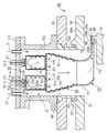
- FIG. 13 is a longitudinal cross-sectional view of a vertical silo-type combustor structure 300 in a supercritical CO 2 gas turbine.
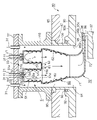
- 14 is a diagram showing the XX section of FIG. 13.
- Combustor structure 300 includes combustor 310 , aft liner 320 and scroll 330 .
- Combustor structure 300 also includes a plurality of combustors 310 .
- the combustor structure 300 is arranged through the outer casing 350 and the inner casing 355 from a direction perpendicular to the axial direction of the turbine rotor 340 .
- a combustor casing 360 surrounding the combustor structure 300 is provided outside the outer casing 350 .
- the other end of combustor casing 360 is closed with head plate 361 .
- a sleeve 351 is provided between an outer casing 350 and an inner casing 355 through which the combustor structure 300 passes.
- the combustor 310 includes a combustor liner 311 , a fuel supply section 312 and an oxidant supply section 313 .
- the combustor liner 311 is composed of a tubular member that burns fuel and oxidant.
- a side wall of the combustor liner 311 is provided with a plurality of introduction holes 311a for guiding the supercritical CO 2 flowing outside the combustor liner 311 to the inside.
- the fuel supply section 312 supplies fuel into the combustor liner 311 .
- the oxidant supply unit 313 supplies oxidant into the combustor liner 311 .
- the oxidant supply section 313 is provided in an annular shape around the fuel supply section 312 .
- An annular outlet 313a of the oxidant supply unit 313 is provided with a swirler 314 that forms a swirl flow of the oxidant in order to stabilize the flame and promote mixing of the fuel and the oxidant.
- the swirling directions of the swirling flows formed by the swirlers 314 of the combustors 310 are set in the same direction.
- each combustor liner 311 of each combustor 310 is fitted into the through hole 322 of the upstream end wall 321 provided at the upstream end of the rear liner 320 .
- Each combustor liner 311 communicates with the interior of the rear liner 320 via a through hole 322 .
- the rear liner 320 is a flow path that gathers the combustion gas discharged from the multiple combustors 310 and guides it to the scroll 330 while rectifying it.
- Rear liner 320 is constructed of a tubular member, as shown in FIG. A side wall of the rear liner 320 is provided with a plurality of introduction holes 323 for guiding the supercritical CO 2 flowing outside the rear liner 320 inside.
- the scroll 330 is a flow path that guides the combustion gas discharged from the rear liner 320 in the axial direction of the turbine rotor 340 and in the circumferential direction of the turbine rotor 340 .
- the scroll 330 has a curved flow path portion 331 that guides the combustion gas discharged from the rear liner 320 in the axial direction of the turbine rotor 340, and a turbine rotor 340 that guides the combustion gas in the axial direction of the turbine rotor 340. and an annular channel portion 332 leading in the circumferential direction of the rotor 340 .
- An outlet 333 of the annular flow path portion 332 faces the first-stage stationary blade 345.
- the fuel supplied to the fuel supply section 312 and the oxidant supplied to the oxidant supply section 313 form a diffusion flame F within the combustor liner 311 and burn.
- the flow of the oxidant into a swirling flow by the swirler 314 By turning the flow of the oxidant into a swirling flow by the swirler 314, the flow of the combustion gas inside the combustor liner 311 also becomes a swirling flow.
- the swirling direction of the swirling flow of the combustion gas in the combustor liner 311 of each combustor 310 is indicated by solid arrows. As shown in FIG. 14, the swirling direction of the combustion gas in each combustor liner 311 is the same. Note that supercritical CO 2 as a cooling medium is introduced into combustor liner 311 through introduction hole 311 a of combustor liner 311 .
- the combustion gas (including supercritical CO 2 ) discharged from each combustor liner 311 forms one swirling flow in the rear liner 320 and flows through the rear liner 320 .
- the swirling direction of the swirling flow of the combustion gas within the rear liner 320 is indicated by a dashed arrow.
- the swirl direction of the swirl flow in the rear liner 320 is the same as the swirl direction of the combustion gas in the combustor liner 311 .
- the cooling medium, supercritical CO 2 is introduced into the rear liner 320 through the introduction holes 323 of the rear liner 320 .
- the swirling flow of combustion gases (including supercritical CO 2 ) in aft liner 320 enters scroll 330 .
- the combustion gas that has flowed into the curved passage portion 331 of the scroll 330 is deflected by approximately 90 degrees in the axial direction of the turbine rotor 340 .
- the deflected combustion gas then flows into the annular flow path portion 332 .
- the combustion gas that has flowed into the annular flow path portion 332 spreads in the circumferential direction of the turbine rotor 340 .
- the combustion gas is jetted from the outlet 333 of the scroll 330 toward the first-stage stationary blades 345 .
- the swirling flow of combustion gas discharged from the combustor 310 forms one swirling flow within the rear liner 320 . This swirling flow then flows inside the scroll 330 .
- the problem to be solved by the present invention is to jet the combustion gas from the scroll outlet to the first-stage stator vanes at a substantially uniform velocity in the circumferential direction even when a swirling flow of the combustion gas is formed in the combustor. It is another object of the present invention to provide a gas turbine combustor structure capable of
- the gas turbine combustor structure of the embodiment is arranged to penetrate the casing of the gas turbine in a direction perpendicular to the axial direction of the turbine rotor of the gas turbine.
- This gas turbine combustor structure is composed of a plurality of combustors and a tubular body provided downstream of the plurality of combustors in a direction perpendicular to the axial direction of the turbine rotor. a rear liner that collects exhausted combustion gas and guides it downstream; and a rear liner that is connected to the downstream end of the rear liner and guides the combustion gas that is exhausted from the rear liner in the axial direction of the turbine rotor. and a scroll leading in the circumferential direction.
- Each combustor includes a cylindrical combustor liner for combusting fuel and an oxidant, a fuel supply section provided at an upstream end of the combustor liner for supplying fuel into the combustor liner, and the fuel supply.
- an oxidant supply unit that is annularly provided around the combustor liner and that supplies a swirling flow of oxidant into the combustor liner.
- the plurality of combustors are composed of the combustor in which the swirl direction of the swirl flow of the oxidant is clockwise, and the downstream side of the oxidant supply section. and the combustor in which the swirl direction of the swirl flow of the oxidant is counterclockwise when viewed from above.
- FIG. 1 is a system diagram of gas turbine equipment provided with a combustor structure according to a first embodiment
- FIG. It is a figure which shows the longitudinal section of the combustor structure of 1st Embodiment.
- FIG. 3 is a diagram showing a cross section taken along line AA of FIG. 2;
- FIG. 3 is a view showing a BB cross section of FIG. 2;
- FIG. 4 is a diagram schematically showing swirling flows of combustion gas within a closed curve in two adjacent combustors of the combustor structure of the first embodiment;
- FIG. 14 is a diagram showing the pressure distribution of the main flow of combustion gas in the annular flow path portion of the scroll of the combustor structure of the first embodiment and the combustor structure of the comparative example shown in FIG.
- FIG. 6 is a view showing a longitudinal section of a combustor structure according to a second embodiment
- FIG. 6 is a view showing a longitudinal section of a combustor structure of a third embodiment
- It is a figure which shows the longitudinal cross-section of the combustor structure of 4th Embodiment.
- FIG. 10 is a view showing a CC cross section of FIG. 9
- FIG. 11 is a view showing a longitudinal section of a combustor structure having another configuration according to the fourth embodiment
- FIG. 11 is a view showing a longitudinal section of a combustor structure of a fifth embodiment
- 1 shows a longitudinal section of a vertical silo-type combustor structure in a supercritical CO 2 gas turbine
- FIG. FIG. 14 is a view showing the XX section of FIG. 13;
- FIG. 1 is a system diagram of gas turbine equipment 8 having a combustor structure 1 according to the first embodiment.
- the gas turbine equipment 8 includes a combustor structure 1, a fuel supply system 10, an oxygen supply system 20, a carbon dioxide circulation system 30, a turbine 40, a generator 41, and a heat exchange system. and a vessel 42 .
- the combustor structure 1 functions as a gas turbine combustor structure.
- the fuel supply system 10 supplies fuel to the combustor structure 1 .
- the fuel supply system 10 has a pipe 11 .
- This piping 11 is provided between a fuel supply source (not shown) and the combustor structure 1 . Further, the pipe 11 is provided with a flow control valve 12 for adjusting the flow rate of fuel.
- hydrocarbons such as methane and natural gas are used as fuel.
- fuel for example, coal gasification gas fuel containing carbon monoxide and hydrogen can be used.
- the oxygen supply system 20 supplies oxygen to the combustor structure 1.
- the oxygen supply system 20 has a pipe 21 .
- This pipe 21 is provided between an air separation device (not shown) that separates oxygen from the atmosphere and the combustor structure 1 .
- the pipe 21 is equipped with a flow control valve 22 that regulates the flow rate of oxygen. Further, the pipe 21 is equipped with a compressor 23 that pressurizes oxygen.
- the flow control valve 22 is provided between the compressor 23 and the heat exchanger 42 .
- the pipe 21 extends to the combustor structure 1 through the heat exchanger 42 . Since the flow control valve 22 is provided upstream of the heat exchanger 42 , high-temperature oxygen does not flow through the flow control valve 22 .
- Oxygen separated from the atmosphere by an air separator flows through the pipe 21 .
- the oxygen flowing through the pipe 21 is heated by passing through the heat exchanger 42 and supplied to the combustor structure 1 .
- the carbon dioxide circulation system 30 circulates part of the combustion gas discharged from the turbine 40 to the combustor structure 1 .
- the carbon dioxide circulation system 30 has a pipe 31 . This piping 31 is provided between the outlet of the turbine 40 and the combustor structure 1 .
- the piping 31 is equipped with a condenser 32 that removes water vapor contained in the combustion gas.
- the water vapor in the combustion gas passes through the condenser 32 and is condensed into water. Water is discharged to the outside through, for example, a pipe 36 .
- the piping 31 is equipped with a compressor 33 that pressurizes the combustion gas from which water vapor has been removed in the condenser 32 to a critical pressure or higher.
- the condenser 32 and the compressor 33 are provided in the piping 31 in the region through which the combustion gas cooled by the heat exchanger 42 flows.
- the equivalence ratio here is an equivalence ratio calculated based on the fuel flow rate and the oxygen flow rate. In other words, it is the equivalence ratio (equivalence ratio in the overall) when it is assumed that the fuel and oxygen are uniformly mixed.
- the component of the combustion gas (dry combustion gas) from which water vapor has been removed in the condenser 32 is mostly carbon dioxide. Therefore, the combustion gas from which water vapor has been removed is simply referred to as carbon dioxide.
- the medium circulated through the combustor structure 1 is carbon dioxide.
- the combustion gas from which water vapor has been removed may contain, for example, a trace amount of carbon monoxide of 0.2% or less. called.
- carbon dioxide pressurized to a critical pressure or higher by the compressor 33 becomes a supercritical fluid.
- the piping 31 is arranged so as to pass through the heat exchanger 42 twice. That is, the pipe 31 passes through the heat exchanger 42 once between the turbine 40 and the condenser 32 . The pipe 31 then passes through the heat exchanger 42 again between the compressor 33 and the combustor structure 1 .
- the combustion gas discharged from the turbine 40 is cooled by passing through the heat exchanger 42. At this time, heat radiation from the combustion gas heats the oxygen flowing through the pipe 21 and the carbon dioxide circulating to the combustor structure 1 through the pipe 31 .
- the pipe 31 branches between the compressor 33 and the heat exchanger 42 .
- a pipe 34 branched from the pipe 31 is provided with a flow control valve 35 for adjusting the flow rate of carbon dioxide to be discharged to the outside.
- the carbon dioxide discharged to the outside can be used, for example, in EOR (Enhanced Oil Recovery) employed at oil extraction sites.
- one end side (combustor structure 1 side) of the pipe 11 for supplying fuel is branched into a plurality of branches.
- Each branched pipe 11 is connected to each combustor 50 of the combustor structure 1 .
- One end side (the combustor structure 1 side) of the pipe 31 for circulating the carbon dioxide to the combustor structure 1 is, for example, branched into a plurality.
- Supercritical CO 2 supplied from a part of the branched pipe 31 is used to form an oxidant, which is a mixture of supercritical CO 2 and oxygen.
- the remaining branched pipe 31 is used to introduce supercritical CO 2 around the combustor structure 1 as a cooling medium, as shown in FIG. 2, which will be described later.
- One end side (the combustor structure 1 side) of the pipe 21 that supplies oxygen to the combustor structure 1 is branched into a plurality of branches.
- One branched pipe 31 and one branched pipe 21 are connected to the oxidizer supply section 53 of each combustor 50 . Then, the oxygen introduced into the oxidant supply section 53 and the supercritical CO 2 are mixed to form a mixture. This air-fuel mixture is jetted into the combustor liner 51 as an oxidant.
- the method of forming the air-fuel mixture is not limited to this method.
- a mixing chamber made of a housing member having a space inside may be provided.
- some of the branched pipes 31 and 21 are connected to the mixing chamber.
- the air-fuel mixture formed in the mixing chamber is supplied to the oxidant supply section 53 of each combustor 50 through a pipe.
- the pipe 31 may be branched between the heat exchanger 42 and the combustor structure 1, and the branched pipe may be connected to the pipe 21 through which oxygen flows.
- This connecting portion is provided, for example, in the pipe 21 between the heat exchanger 42 and the combustor structure 1 .
- the pipe 31 may be branched between the compressor 33 and the heat exchanger 42, and the branched pipe may be connected to the pipe 21 through which oxygen flows.
- This connecting portion is provided, for example, in the pipe 21 between the flow control valve 22 and the heat exchanger 42 .
- the pipe branched from the pipe 31 is provided with a flow control valve for adjusting the flow of supercritical CO 2 mixed with oxygen.
- the turbine 40 is rotated by combustion gas discharged from the combustor structure 1 .
- a generator 41 is connected to the turbine 40 .
- FIG. 2 is a view showing a longitudinal section of the combustor structure 1 of the first embodiment.
- FIG. 3 is a diagram showing a cross section along line AA of FIG.
- FIG. 4 is a diagram showing a BB section of FIG. 2 to 4 are cross-sectional views of the combustor structure 1 installed in a gas turbine. Therefore, FIGS. 2 to 4 also show the configuration of, for example, the casing of the gas turbine. 2 and 3 show the configuration of the upper half. Here, an example in which the combustor structure 1 is provided on the upper half side is shown.
- the combustor structure 1 is installed in a supercritical CO2 gas turbine that uses supercritical CO2 as the working fluid. Since the combustor structure 1 and the turbine 40 are operated under extremely high pressure conditions, the casing 80 has a double casing structure including an inner casing 90 and an outer casing 85, as shown in FIGS. be done.
- the outer casing 85 is provided on the outer peripheral side of the inner casing 90 with a predetermined gap.
- stationary blades 95 and moving blades 96 are alternately arranged in the axial direction of the turbine rotor 97 .
- the stationary blade 95 is arranged between the inner ring side wall 95a and the outer ring side wall 95b.
- the rotor blades 96 are provided on rotor wheels 98 of a turbine rotor 97 .
- An outer wall 95c is provided on the outer periphery of the moving blade 96 with a gap from the tip of the moving blade 96. As shown in FIG.
- the outer wall 95c may be configured by extending the outer ring side wall 95b in the axial direction of the turbine rotor 97, for example.
- the combustor structure 1 includes a combustor 50, a rear liner 60, and a scroll 70.
- the combustor structure 1 also includes a plurality of combustors 50 .
- the number of combustors 50 to be arranged is determined, for example, based on the amount of heat that can be supplied from one combustor 50 and the amount of heat required for the supercritical CO 2 gas turbine.
- the combustor structure 1 is arranged through the outer casing 85 and the inner casing 90 from a direction perpendicular to the axial direction of the turbine rotor 97, as shown in FIGS.
- the combustor structure 1 is a so-called vertical silo type combustor structure.
- an example of penetrating the combustor structure 1 from vertically above is shown.
- a combustor casing 110 surrounding the combustor structure 1 is provided outside the outer casing 85 .
- Combustor casing 110 is configured as a cylindrical casing that is open at both ends.
- One end of the combustor casing 110 is fixed to the outer casing 85 .
- the other end of combustor casing 110 is closed with head plate 111 .
- the head plate 111 is provided with through holes (not shown) for drawing the pipes 21 , 31 , and 11 into the combustor casing 110 .
- the outer casing 85 and the inner casing 90 are formed with through holes 86 and 91 through which the combustor structure 1 is passed.
- a sleeve 100 is provided between an outer casing 85 and an inner casing 90 through which the combustor structure 1 passes.
- the sleeve 100 prevents supercritical CO 2 as a cooling medium flowing around the combustor structure 1 from flowing out into the space between the outer casing 85 and the inner casing 90 .
- the sleeve 100 is composed of, for example, a cylindrical member.
- annular protrusion 92 is formed around the sleeve 100 with a gap from the sleeve 100 .
- the ridge portion 92 protrudes toward the outer casing 85 side.
- An annular seal ring 93 is fitted between the sleeve 100 and the ridge portion 92 .
- the combustor 50 includes a combustor liner 51 , a fuel supply section 52 and an oxidant supply section 53 .
- the combustor liner 51 is composed of a cylindrical member that burns fuel and oxidant. One end (upstream end) of the combustor liner 51 is closed with an upstream end wall 51a, and the other end (downstream end) is open.
- the combustor liner 51 is composed of, for example, a cylindrical body extending linearly. Note that the combustor liner 51 may be configured by, for example, a partially curved tubular body.
- the upstream end wall 51 a has an opening 51 b for providing the fuel supply portion 52 and the oxidant supply portion 53 .
- upstream means upstream in the direction in which the combustion gas flows
- downstream means downstream in the direction in which the combustion gas flows
- the combustor liner 51 is arranged such that the central axis of the combustor liner 51 is perpendicular to the axial direction of the turbine rotor 97, for example.
- the side wall of the combustor liner 51 is provided with a plurality of introduction holes 51c for guiding the supercritical CO 2 flowing outside the combustor liner 51 to the inside.
- the supercritical CO 2 flowing outside the combustor liner 51 has the function of cooling the combustor liner 51 .
- the introduction hole 51c is configured by, for example, a slit or a hole.
- Combustor liner 51 is cooled, for example, by film cooling.
- film cooling is applied, supercritical CO 2 as a cooling medium introduced from the introduction hole 51c forms a gaseous heat insulating film between the inner wall surface of the combustor liner 51 and the combustion gas. This prevents the inner wall surface of the combustor liner 51 from directly contacting the combustion gas.
- the fuel supply unit 52 supplies fuel into the combustor liner 51 .
- the fuel supply portion 52 is provided on the upstream end wall 51 a of the combustor liner 51 .
- the fuel supply portion 52 is provided at the center of the upstream end wall 51a.
- the fuel supply unit 52 is configured by, for example, a circular tube.
- the fuel supply unit 52 is connected to the pipe 11 for supplying fuel.
- the outlet 52a of the fuel supply section 52 functions as, for example, a fuel nozzle.
- the outlet 52a is composed of, for example, a single-hole fuel injection hole or a multi-hole fuel injection hole.
- the fuel is jetted into the combustor liner 51 from the outlet 52 a of the fuel supply section 52 .
- the oxidant supply unit 53 supplies the oxidant into the combustor liner 51 .
- the oxidizer supply portion 53 is provided on the upstream end wall 51 a of the combustor liner 51 .
- the oxidant supply section 53 is provided around the fuel supply section 52 concentrically with the fuel supply section 52 and in an annular shape.
- the annular oxidant supply section 53 is configured by, for example, providing a circular tube on the outer periphery of the fuel supply section 52 .
- the fuel supply section 52 and the oxidant supply section 53 are configured with a double pipe structure.
- the fuel is ejected from a central fuel ejection hole, and the oxidant is ejected from an annular channel formed around the central fuel ejection hole. That is, the combustor 50 employs a diffusion combustion method.
- the annular outlet 53a of the oxidant supply unit 53 is provided with, for example, a swirler 55 that forms a swirling flow of the oxidant.
- the swirler 55 has a plurality of blades circumferentially arranged in an annular passage. The vanes are arranged at a predetermined angle with respect to the axial direction of the annular passage.
- a swirl flow having a circumferential velocity component is ejected into the combustor liner 51 .
- mixing of the fuel and the oxidant is promoted in the combustor liner 51, and a stable flame is formed.
- the plurality of combustors 50 are arranged at equal intervals on a predetermined circumference, for example.
- 4 is a cross-sectional view of the combustor 50 viewed from the downstream side of the combustor liner 51.
- the predetermined circumference is, for example, a circumference centered on the central axis of the combustor casing 110 or a circumference centered on the center of the opening (circular opening) at the upstream end of the rear liner 60 .
- the swirl direction of the swirl flow of the oxidant supplied from the oxidant supply unit 53 is clockwise.
- the combustor 50 in which the swirling direction of the swirling flow of the oxidant is clockwise when viewed from the downstream side of the oxidant supply unit 53 is referred to as the oxidant-clockwise combustor 50
- the oxidant-counterclockwise combustor 50 the combustor 50 in which the swirling direction of the swirling flow of the oxygen is counterclockwise.
- the multiple combustors 50 are configured with an even number of combustors 50 .
- the arrangement configuration shown in FIG. 4 is configured such that the swirling directions of the swirling flow of the oxidant in the combustors 50 adjacent in the circumferential direction are opposite to each other. That is, the oxidant-clockwise combustors 50 and the oxidant-counterclockwise combustors 50 are alternately arranged in the circumferential direction.
- the flow of combustion gas in the combustor liner 51 depends on the swirling direction of the oxidant. That is, the flow of the combustion gas in the combustor liner 51 becomes a swirling flow in the same swirling direction as the swirling direction of the swirling flow of the oxidant.
- each combustor 50 in the rear liner 60 an even number of combustors 50 should be provided, half of which are oxidizer-clockwise combustors 50. , and the remaining half of the oxidizer-counterclockwise combustor 50 is preferred.
- the swirler 55 provided in the oxidant supply section 53 of each combustor 50 have the same specifications such as the size and outlet angle.
- the number of oxidizer-clockwise combustors 50 and the number of oxidizer-counterclockwise combustors 50 to be installed may be arbitrarily set.
- each of the oxidant-clockwise combustor 50 and the oxidant-counterclockwise combustor 50 is included.
- the ratio of the circumferential velocity component to the axial velocity component in the swirl flow of the oxidant in the combustor 50 may be increased.
- the swirler 55 may be designed such that the clockwise and counterclockwise swirl flows interfere in the flow field of the combustion gas within the rear liner 60, canceling out each other's circumferential velocity components. preferable.
- FIG. 4 shows an example in which the oxidizer-clockwise combustors 50 and the oxidizer-counterclockwise combustors 50 are alternately arranged in the circumferential direction.
- each combustor 50 is arranged circumferentially. may be placed consecutively.
- FIG. 4 shows an example in which a plurality of combustors 50 are arranged at equal intervals on a predetermined circumference, but the arrangement is not limited to this.
- the multiple combustors 50 may be configured in multiple rows. For example, when arranging six combustors 50, three combustors 50 may be arranged in a straight line and arranged in two rows.
- one combustor 50 described above includes one combustor liner 51 and one fuel-oxidizer supply mechanism 54 provided at the upstream end of this one combustor liner 51 . Then, as shown in FIG. 2, one diffusion flame F is formed on the downstream side of one fuel-oxidant supply mechanism 54 .
- one fuel-oxidizer supply mechanism 54 may include a plurality of fuel supply units 52 and a plurality of oxidizer supply units 53 .
- the swirl directions of the swirl flows supplied from the respective oxidant supply units 53 are set in the same direction.
- each combustor liner 51 of each combustor 50 communicates with the inside of the rear liner 60 via a through hole 63 .
- each combustor 50 is connected to the branched pipe 11 respectively.
- the oxidant supply unit 53 of each combustor 50 is connected to, for example, the branched pipes 21 and 31 respectively.
- oxygen and supercritical CO 2 introduced in the upstream portion of the oxidant supply section 53 are mixed while flowing through the oxidant supply section 53, and oxygen and supercritical CO 2 are mixed at the outlet 53a of the oxidant supply section 53.
- the rear liner 60 is provided downstream of the multiple combustors 50, as shown in FIG.
- the rear liner 60 is a flow path that gathers combustion gas discharged from the plurality of combustors 50 and directs it to the scroll 70 while rectifying it.
- the rear liner 60 is, for example, composed of a tubular member extending in a direction perpendicular to the axial direction of the turbine rotor 97, as shown in FIGS. Further, the rear liner 60 has, for example, a channel portion in which the channel cross-sectional area gradually decreases toward the downstream side. Note that the shape of the rear liner 60 is not limited to this.
- One end (upstream end) of the rear liner 60 is closed with a flat upstream end wall 61, and the other end (downstream end) is open.
- the upstream end wall 61 has a plurality of through holes 63 communicating with the downstream end of each combustor liner 51 as described above. This through-hole 63 is formed in accordance with the position of the downstream end of each combustor liner 51 .
- the other end (downstream end) of the rear liner 60 is connected to the upstream end of the scroll 70 .
- a side wall of the rear liner 60 is provided with a plurality of introduction holes 62 for guiding the supercritical CO 2 flowing outside the rear liner 60 inside.
- the supercritical CO 2 flowing outside this rear liner 60 has the function of cooling the rear liner 60 .
- the configuration of the introduction hole 62 is the same as the configuration of the introduction hole 51c described above. Further, the effect of providing the introduction hole 62 is the same as the effect of providing the introduction hole 51c described above.
- the scroll 70 is a flow path that guides the combustion gas discharged from the rear liner 60 in the axial direction of the turbine rotor 97 and in the circumferential direction of the turbine rotor 97 .
- the scroll 70 includes a curved flow path portion 71 that guides the combustion gas discharged from the rear liner 60 in the axial direction of the turbine rotor 97 and a combustion flow path portion that guides the combustion gas in the axial direction of the turbine rotor 97 . and an annular flow path portion 72 that guides the gas in the circumferential direction of the turbine rotor 97 .
- the upstream end of the curved channel portion 71 is connected to the downstream end of the rear liner 60 .
- the bent flow path portion 71 is composed of a bent pipe that bends about 90 degrees in the axial direction of the turbine rotor 97 .
- the outlet side of the curved flow path portion 71 has a configuration that widens in the circumferential direction of the turbine rotor 97 while being curved.
- the bent channel portion 71 deflects the flow of the combustion gas discharged from the rear liner 60 by approximately 90 degrees. The deflected flow of combustion gas flows in the axial direction of the turbine rotor 97 .
- the annular flow path portion 72 is composed of an annular tube provided to cover the circumference of the turbine rotor 97 . Note that the annular flow path portion 72 is configured, for example, by combining split structures composed of a semi-annular upper half portion and a lower half portion.
- the annular flow path portion 72 widens the flow of combustion gas discharged from the curved flow path portion 71 in the circumferential direction of the turbine rotor 97 .
- the combustion gas having velocity components in the axial direction of the turbine rotor 97 spreads uniformly in the circumferential direction of the turbine rotor 97 .
- the outlet 73 of the annular flow path portion 72 faces the first-stage stationary blade 95.
- the combustion gas flowing through the annular flow path portion 72 is jetted out from the outlet 73 toward the first-stage stationary blade 95 .
- the outlet end of the annular flow path portion 72 is in contact with the upstream ends of the inner ring side wall 95a and the outer ring side wall 95b. As a result, the combustion gas ejected from the outlet 73 is guided to the first stage stationary blade 95 .
- fuel is supplied to the combustor 50 of the combustor structure 1 through the pipe 11 .
- Oxygen separated from the atmosphere is supplied to combustor 50 through piping 21 .
- the oxygen is pressurized to a predetermined pressure by the compressor 23 .
- the pressurized oxygen is heated by passing through heat exchanger 42 .
- circulating supercritical CO 2 is supplied to the combustor structure 1 and combustor 50 through piping 31 . At this time, the supercritical CO 2 is heated by passing through the heat exchanger 42 .
- the oxygen and supercritical CO 2 supplied to the combustor 50 are mixed and ejected as an oxidant into the combustion area within the combustor liner 51 .
- the fuel and oxidant guided to the combustor 50 of the combustor structure 1 are combusted in the combustor liner 51 to become combustion gas. Since the operation of the combustor structure 1 will be described later, a detailed description thereof will be omitted here.
- the combustion gas discharged from the combustor structure 1 is introduced into the turbine 40 .
- Turbine 40 is rotated by combustion gases.
- the generator 41 is driven by the rotation of the turbine 40 to generate electricity.
- the combustion gas discharged from the combustor structure 1 here contains combustion products produced by fuel and oxygen and carbon dioxide circulating in the combustor structure 1 .
- the combustion gas discharged from the turbine 40 is guided to the piping 31 and cooled by passing through the heat exchanger 42 .
- the oxygen flowing through the pipe 21 and the carbon dioxide flowing through the pipe 31 and circulating to the combustor structure 1 are heated by heat radiation from the combustion gas.
- the combustion gas that has passed through the heat exchanger 42 passes through the condenser 32 .
- water vapor contained in the combustion gas is removed.
- Water vapor in the combustion gas is condensed into water by passing through the condenser 32 .
- Water is discharged to the outside through, for example, a pipe 36 .
- Carbon dioxide is pressurized by a compressor 33 intervening in pipe 31 to become supercritical CO 2 .
- Part of the carbon dioxide pressurized by the compressor 33 flows through the piping 31 and is circulated to the combustor structure 1 .
- the supercritical CO 2 is heated to about 700° C., for example, by passing through the heat exchanger 42 .
- the rest of the carbon dioxide pressurized by the compressor 33 is introduced into the pipe 34 branching from the pipe 31 .
- the carbon dioxide introduced into the pipe 34 has its flow rate adjusted by the flow control valve 35 and is discharged to the outside.
- FIG. 1 the action of the combustor structure 1 will be described with reference to FIGS. 2 and 3.
- FIG. 2 the action of the combustor structure 1 will be described with reference to FIGS. 2 and 3.
- combustors 50 are arranged on a predetermined circle at regular intervals, and oxidant-clockwise combustors 50 and oxidant-counterclockwise combustors 50 are arranged around the circle. A case where they are arranged alternately in the direction will be described as an example.
- the fuel supplied from the pipe 11 to the fuel supply section 52 is jetted into the combustor liner 51 from the outlet 52a.
- the oxygen supplied from the pipe 21 to the oxidant supply unit 53 and the supercritical CO 2 supplied from the pipe 31 to the oxidant supply unit 53 are mixed in the oxidant supply unit 53, and are discharged into the combustor liner 51 from the outlet 53a. is ejected to. At this time, a swirling flow is formed by the supercritical CO 2 passing through the swirler 55 provided at the outlet 53a.
- the mixture of fuel and oxidant in the combustor liner 51 is ignited by an ignition device (not shown) and combustion begins.
- An ignition device is provided in each combustor 50 .
- each combustor 50 the swirling flow of the oxidant promotes mixing of the fuel and the oxidant.
- the swirling flow of the oxidant forms a recirculation zone in the combustion zone to form a stable flame.
- the flow of combustion gas in the combustor liner 51 becomes a swirling flow in the same swirling direction as the swirling direction of the swirling flow of the oxidant. That is, when viewed in the circumferential direction, a swirling flow of combustion gas with swirling directions alternately opposite to each other is discharged from the combustor liner 51 to the rear liner 60 .
- the combustion reaction is completed within the combustor liner 51. Therefore, the combustion gas discharged from the outlet of the combustor liner 51 does not contain oxygen and fuel, and is composed mostly of carbon dioxide and water vapor.
- the supercritical CO 2 supplied to the periphery of the combustor structure 1 from the pipe 31 passes through the introduction hole 51c of the combustor liner 51 and is introduced into the combustor liner 51 as a cooling medium.
- the supercritical CO 2 introduced into the combustor liner 51 is discharged from the outlet of the combustor liner 51 together with the combustion gas and flows into the rear liner 60 .
- Combustion gases (including supercritical CO 2 ) discharged from combustor liner 51 of each combustor 50 flow in aft liner 60 toward scroll 70 .
- the supercritical CO 2 supplied from the pipe 31 to the periphery of the combustor structure 1 passes through the introduction hole 62 of the rear liner 60 and is introduced into the rear liner 60 as a cooling medium.
- Supercritical CO 2 introduced into aft liner 60 flows into scroll 70 with the combustion gases.
- the combustion gas (including supercritical CO 2 ) that has flowed into the curved passage portion 71 of the scroll 70 is deflected by approximately 90 degrees in the axial direction of the turbine rotor 97 .
- the deflected combustion gas flows into the annular flow path portion 72 .
- the combustion gas that has flowed into the annular flow path portion 72 spreads in the circumferential direction of the turbine rotor 97 .
- the flow of combustion gas flowing into the scroll 70 is a flow that has almost no circumferential velocity component. Therefore, the flow that spreads from the curved channel portion 71 to the annular channel portion 72 spreads uniformly in the left-right direction (clockwise direction and counterclockwise direction) of the annular channel portion 72 in the cross section shown in FIG. 3, for example. As a result, the combustion gas flow has a substantially uniform velocity distribution within the annular flow path of the annular flow path portion 72 surrounding the turbine rotor 97 .
- the combustion gas is jetted from the outlet 73 of the scroll 70 toward the first stage stationary blade 95 .
- the combustion gas is jetted out from the annular outlet at a substantially uniform velocity in the circumferential direction.
- the combustion gas that has flowed through the combustor structure 1 is guided to the turbine 40 to operate the turbine 40 .
- the circulation ⁇ (circulation) around the closed curve S the value obtained by line-integrating the velocity component Vs in the direction along this closed curve for the entire circumference of this closed curve.
- Circulation ⁇ is defined by the following equation (1).
- combustors 50 in which the swirling direction of the swirling flow of the combustion gas is counterclockwise are alternately arranged in the circumferential direction.
- combustion gas-clockwise combustor 50 in which the swirling direction of the swirling flow of the combustion gas is clockwise when viewed from the downstream side of the combustor 50
- combustion gas-counterclockwise combustor 50 in which the swirling direction of the flow is counterclockwise
- combustion gas-counterclockwise combustor 50 means the oxidant-counterclockwise combustor 50.
- the same combustor 50 is meant.
- FIG. 5 is a diagram schematically showing swirling flows of combustion gas within a closed curve in two adjacent combustors 50 of the combustor structure 1 of the first embodiment.
- the two combustors 50 one is a combustion gas-clockwise combustor 50 and the other is a combustion gas-counterclockwise combustor 50 .
- arrows indicate the swirling direction of the swirling flow of the combustion gas.
- FIG. 5 comprises a closed curve S1 consisting of ABCD and a closed curve S2 consisting of B'-ADC'.
- the sum of cyclic ⁇ for these closed curves S1 and S2 is given by the following equation (2).
- Equation (2) the sum of the circulations ⁇ indicated by Equation (2) is "0".
- the sum of circulation ⁇ is "0" as a whole. becomes.
- FIG. 6 shows the pressure distribution of the main stream of combustion gas in the annular passage portion of the scroll in the combustor structure 1 of the first embodiment and the combustor structure 300 as the comparative example shown in FIG. It is a figure which shows.
- the result of the CFD analysis shown in FIG. 6 is the pressure distribution inside the annular flow path at the position corresponding to the cross section AA in FIG. Further, the results of the CFD analysis show the results at the center of the annular flow path portion 72 along the counterclockwise and clockwise directions about the central axis P of the turbine rotor 97 from the upper half upper central position Q.
- the upper half upper central position Q is the central position in the annular flow path portion 72 vertically above the central axis P of the turbine rotor 97, as shown in FIG.
- the definition of the upper half upper center position Q is the same for the annular flow path portion 332 of the combustor structure 300 of the comparative example.
- the combustion gas-clockwise combustors 50 and the combustion gas-counterclockwise combustors 50 are alternately arranged in the circumferential direction in the arrangement shown in FIG.
- CFD analysis was performed with the specifications.
- CFD analysis was performed under rated operating conditions in the gas turbine equipment 8 .
- the vertical axis in FIG. 6 is the static pressure of the mainstream of the combustion gas flowing through the annular flow path.
- the horizontal axis in FIG. 6 is the circumferential position of the annular flow path portion.
- the central position Q of the upper half upper portion of the annular channel portion in FIG. 3 is 0 degrees.
- the position 90 degrees counterclockwise about the central axis P of the turbine rotor 97 from the upper half upper center position Q is defined as 90 degrees, and the position 90 degrees clockwise from the upper half upper center position Q. is -90 degrees.
- the pressure distribution on the counterclockwise side of the upper half upper center position Q and the pressure distribution on the clockwise side of the upper half upper center position Q It is different from the pressure distribution on the turning side. That is, the pressure distribution of the combustion gas flowing into the annular flow path portion 332 from the curved flow path portion 331 becomes uneven in the circumferential direction.
- the pressure distribution on the counterclockwise side of the upper half upper center position Q and the pressure distribution on the clockwise side of the upper half upper center position Q shows almost the same distribution as the pressure distribution on the side. That is, the pressure distribution of the combustion gas flowing from the curved channel portion 71 into the annular channel portion 72 becomes uniform in the circumferential direction.
- the combustion gas-clockwise combustor 50 and the combustion gas-counterclockwise combustor 50 are provided as the plurality of combustors 50.
- the clockwise swirling flow and the counterclockwise swirling flow interfere to cancel out the circumferential velocity component.
- annular flow path portion 72 of the scroll 70 a uniform combustion gas velocity distribution in the circumferential direction can be obtained.
- the combustion gas can be ejected from the outlet 73 of the scroll 70 (annular flow path portion 72) to the first-stage stationary blades 95 at a substantially uniform speed over the circumferential direction.
- combustor 50 in the combustor structure 1 of the first embodiment in one space in one combustor liner 51, by ejecting a swirling flow of oxidant from the oxidant supply part 53, Acceleration of mixing of fuel and oxidant and stabilization of flame can be realized.
- FIG. 7 is a view showing a longitudinal section of the combustor structure 2 of the second embodiment.
- the same components as those of the combustor structure 1 of the first embodiment are denoted by the same reference numerals, and overlapping descriptions are omitted or simplified.
- the system diagram of the gas turbine equipment is the same as the system diagram of the gas turbine equipment described in the first embodiment.
- the configuration of the combustor structure 2 of the second embodiment is basically the same as that of the combustor structure 1 of the first embodiment except that the reverse swirl imparting section 120 is provided. Therefore, here, the configuration of the reverse turning imparting section 120 will be mainly described.
- each combustor 50 of the combustor structure 1 has a reverse swirl imparting section 120 at the outlet of the combustor liner 51 .
- the reverse swirl imparting part 120 is arranged, for example, so as to block the outlet of the combustor liner 51 .
- the reverse swirl imparting part 120 is composed of an annular swirler. The structure of the swirler is as described in the first embodiment.
- the reverse swirl imparting section 120 imparts swirl to the combustion gas flow passing through the reverse swirl imparting section 120 in a direction opposite to the swirling direction of the swirling flow of the oxidant. That is, the swirl direction imparted to the flow of combustion gas by the reverse swirl imparting section 120 is opposite to the swirling direction of the swirl flow of the combustion gas on the upstream side of the reverse swirl imparting section 120 .
- the swirling direction of the swirling flow of the oxidant in each combustor 50 is not particularly limited. That is, the swirling direction of the swirling flow of the oxidant in each combustor 50 may be clockwise or counterclockwise.
- the swirler that constitutes the reverse swirl imparting section 120 is designed to eliminate the circumferential velocity component in the swirling flow of the combustion gas flowing into the reverse swirl imparting section 120 .
- the combustion gas passes through the reverse swirl imparting section 120, thereby attenuating the swirling flow of the combustion gas.
- the flow of combustion gas entering the rear liner 60 becomes a flow that has substantially no circumferential velocity component.
- the flow that spreads from the curved flow path section 71 to the annular flow path section 72 spreads uniformly in the left-right direction (clockwise direction and counterclockwise direction) of the annular flow path section 72 in the cross section shown in FIG. 3, for example.
- the combustion gas flow has a substantially uniform velocity distribution within the annular flow path of the annular flow path portion 72 surrounding the turbine rotor 97 .
- the combustion gas can be ejected from the outlet 73 of the scroll 70 (annular flow path portion 72) to the first-stage stationary blades 95 at a substantially uniform speed over the circumferential direction.
- FIG. 8 is a view showing a longitudinal section of the combustor structure 3 of the third embodiment.
- a combustor structure 3 according to the third embodiment has basically the same configuration as the combustor structure 1 according to the first embodiment, except that a CO 2 swirl flow introducing section 130 is provided. Therefore, here, the configuration of the CO 2 swirl flow introduction section 130 will be mainly described.
- each combustor 50 of the combustor structure 3 is provided with an annular CO 2 swirl flow introduction section 130 on the outer circumference of the outlet of the combustor liner 51 .
- the CO 2 swirl flow introduction section 130 swirls supercritical CO 2 as a cooling medium supplied from the pipe 31 into the combustor casing 110 to introduce a swirl flow of the supercritical CO 2 into the rear liner 60 .
- the CO 2 swirling flow introduction section 130 is configured with an annular swirler.
- the swirl direction of the supercritical CO 2 swirl flow introduced into the rear liner 60 from the CO 2 swirl flow introduction part 130 is the swirl direction of the combustion gas discharged from the combustor liner 51 provided with the CO 2 swirl flow introduction part 130 . This is the direction opposite to the swirling direction of the flow.
- the swirling direction of the swirling flow of the oxidant in each combustor 50 is not particularly limited. That is, the swirling direction of the swirling flow of the oxidant in each combustor 50 may be clockwise or counterclockwise.
- the flow rate of supercritical CO 2 introduced into the rear liner 60 from each CO 2 swirl flow introduction part 130 and the ratio of the circumferential velocity component to the axial velocity component in the swirl flow are the combustion exhausted from the combustor liner 51. It is set so as to cancel out the circumferential velocity component of the swirl flow of the gas flow.
- the flow that spreads from the curved flow path section 71 to the annular flow path section 72 spreads uniformly in the left-right direction (clockwise direction and counterclockwise direction) of the annular flow path section 72 in the cross section shown in FIG. 3, for example.
- the combustion gas flow has a substantially uniform velocity distribution within the annular flow path of the annular flow path portion 72 surrounding the turbine rotor 97 .
- the combustion gas can be ejected from the outlet 73 of the scroll 70 (annular flow path portion 72) to the first-stage stationary blades 95 at a substantially uniform speed over the circumferential direction.
- FIG. 9 is a view showing a longitudinal section of the combustor structure 4 of the fourth embodiment.
- FIG. 10 is a diagram showing a CC cross section of FIG.
- a combustor structure 4 according to the fourth embodiment has basically the same configuration as the combustor structure 1 according to the first embodiment, except that a CO 2 swirling flow introducing section 140 is provided. Therefore, here, the configuration of the CO 2 swirl flow introduction section 140 will be mainly described.
- the combustor structure 4 has a CO 2 swirl flow introduction section 140 formed in the rear liner 60 .
- the CO 2 swirl flow introduction part 140 is formed in the circumferential direction of the side wall of the rear liner 60 at a predetermined position in the central axis direction of the rear liner 60 .
- the CO 2 swirling flow introduction part 140 is composed of a plurality of through holes penetrating the rear liner 60 in a direction inclined at a predetermined angle with respect to the direction (radial direction) toward the central axis O of the rear liner 60 .
- the through-holes penetrate the rear liner 60 in a tangential direction to the inner peripheral surface of the rear liner 60, for example.
- Each through-hole which is the CO 2 swirling flow introduction part 140 , ejects supercritical CO 2 as a cooling medium supplied from the pipe 31 into the combustor casing 110 , thereby causing the supercritical CO 2 to flow into the rear liner 60 . Form a swirling flow.
- the swirling direction of the swirling flow of the oxidant in each combustor 50 is set to the same direction. That is, the swirling direction of the swirling flow of the combustion gas discharged from each combustor liner 51 is also the same direction.
- the plurality of through-holes which are the CO 2 swirling flow introduction portions 140 , form a swirling flow of supercritical CO 2 in a direction opposite to the swirling direction of the swirling flow of the combustion gas discharged from each combustor liner 51 .
- arrows indicate the swirling direction of the swirling flow of the combustion gas in the combustor liner 51 of each combustor 50 and the ejection direction of the supercritical CO 2 ejected from the through holes.
- the CO 2 swirl flow introduction part 140 is preferably formed on the inlet side of the rear liner 60 , that is, on the upstream part of the rear liner 60 .
- the CO 2 swirl flow introducing portions 140 may be formed at a plurality of predetermined positions in the central axis direction of the rear liner 60 .
- the CO 2 swirl flow introduction part 140 may be formed in multiple stages in the central axis direction of the rear liner 60 .
- the flow rate of supercritical CO 2 introduced into the rear liner 60 from the CO 2 swirl flow introduction part 140 and the inclination angle of the through hole that is the CO 2 swirl flow introduction part 140 with respect to the direction toward the central axis O are is set so as to cancel out the circumferential velocity component of the swirling flow of the combustion gas formed at .
- a swirling flow swirling in one direction is formed in the rear liner 60 by the combustion gas discharged from each combustor liner 51 .
- a swirling flow of supercritical CO 2 is formed in the rear liner 60 in a direction opposite to the swirling direction of the flow of the combustion gas by the supercritical CO 2 ejected from the through hole, which is the CO 2 swirling flow introducing portion 140 . .
- the swirling flow of combustion gas is then attenuated by the swirling flow of supercritical CO2 . This results in a flow of combustion gas that has substantially no circumferential velocity component while flowing through the rear liner 60 .
- the flow that spreads from the curved flow path section 71 to the annular flow path section 72 spreads uniformly in the left-right direction (clockwise direction and counterclockwise direction) of the annular flow path section 72 in the cross section shown in FIG. 3, for example.
- the combustion gas flow has a substantially uniform velocity distribution within the annular flow path of the annular flow path portion 72 surrounding the turbine rotor 97 .
- the swirl flow of the combustion gas is changed to the supercritical CO 2 swirl flow.
- the combustion gas can be ejected from the outlet 73 of the scroll 70 (annular flow path portion 72) to the first-stage stationary blades 95 at a substantially uniform speed over the circumferential direction.
- the configuration of the CO 2 swirling flow introducing section 140 in the combustor structure 4 of the fourth embodiment is not limited to the configuration described above.
- FIG. 11 is a longitudinal cross-sectional view of another configuration of the combustor structure 4 of the fourth embodiment.
- the CO 2 swirl flow introduction part 140 may be composed of an annular swirler provided on the upstream end wall 61 provided at the upstream end of the rear liner 60 .
- An annular swirler is formed along the outer edge of the upstream end wall 61 in the circumferential direction.
- the swirler which is the CO 2 swirling flow introduction part 140 , ejects the supercritical CO 2 supplied from the pipe 31 into the combustor casing 110 to form a swirling flow of supercritical CO 2 in the rear liner 60 .
- the swirling direction of the flow of combustion gas discharged from each combustor liner 51 is also the same direction.
- the swirling direction of the swirling flow of supercritical CO 2 ejected from the CO 2 swirling flow introducing portion 140 is opposite to the swirling direction of the flow of combustion gas discharged from each combustor liner 51 .
- the flow rate of supercritical CO 2 introduced into the rear liner 60 from the CO 2 swirl flow introduction part 140 and the ratio of the circumferential velocity component to the axial direction velocity component of the swirler constituting the CO 2 swirl flow introduction part 140 are It is set so as to cancel out the circumferential velocity component of the swirling flow of the combustion gas formed within 60 .
- FIG. 12 is a view showing a longitudinal section of the combustor structure 5 of the fifth embodiment.
- the combustor structure 5 of the fifth embodiment has basically the same configuration as the combustor structure 1 of the first embodiment, except that a CO 2 swirling flow introducing section 150 is provided. Therefore, here, the configuration of the CO 2 swirl flow introduction section 150 will be mainly described.
- the combustor structure 5 includes a CO 2 swirl flow introduction section 150 on the upstream end wall 61 provided at the upstream end of the rear liner 60 .
- the CO 2 swirl flow introduction part 150 is composed of an annular swirler provided at the center of the through-hole 63 provided on a predetermined circumference corresponding to each combustor liner 51 .
- the swirler which is the CO 2 swirling flow introduction part 150 , ejects the supercritical CO 2 as the cooling medium supplied from the pipe 31 into the combustor casing 110 , thereby creating a swirling flow of supercritical CO 2 in the rear liner 60 .
- the swirling direction of the swirling flow of the oxidant in each combustor 50 is set to the same direction. That is, the swirling direction of the swirling flow of the combustion gas discharged from each combustor liner 51 is also the same direction.
- the swirling direction of the swirling flow of supercritical CO 2 ejected from the CO 2 swirling flow introducing portion 150 is opposite to the swirling direction of the flow of combustion gas discharged from each combustor liner 51 .
- the flow rate of supercritical CO 2 introduced into the rear liner 60 from the CO 2 swirl flow introduction section 150 and the ratio of the circumferential velocity component to the axial velocity component of the swirler constituting the CO 2 swirl flow introduction section 150 are It is set so as to cancel out the circumferential velocity component of the swirling flow of the combustion gas formed within 60 .
- a swirling flow swirling in one direction is formed in the rear liner 60 by the combustion gas discharged from each combustor liner 51 .
- a swirling flow of supercritical CO 2 is formed in the rear liner 60 in a direction opposite to the swirling direction of the flow of the combustion gas by the supercritical CO 2 ejected from the swirler, which is the CO 2 swirling flow introducing portion 150 .
- This swirling flow of supercritical CO 2 is formed at the swirling central portion of the swirling flow of combustion gas.
- the swirling flow of combustion gas is then attenuated by the swirling flow of supercritical CO2 . This results in a flow of combustion gas that has substantially no circumferential velocity component while flowing through the rear liner 60 .
- the flow that spreads from the curved flow path section 71 to the annular flow path section 72 spreads uniformly in the left-right direction (clockwise direction and counterclockwise direction) of the annular flow path section 72 in the cross section shown in FIG. 3, for example.
- the combustion gas flow has a substantially uniform velocity distribution within the annular flow path of the annular flow path portion 72 surrounding the turbine rotor 97 .
- the swirl flow of the combustion gas is changed to the supercritical CO 2 swirl flow.
- the combustion gas can be ejected from the outlet 73 of the scroll 70 (annular flow path portion 72) to the first-stage stationary blades 95 at a substantially uniform speed over the circumferential direction.
- the combustor structure 3 of the third embodiment when the swirling directions of the swirling flows of the combustion gas discharged from the combustor liners 51 are the same (when the swirling directions of the swirling flows of the oxidizer in the combustors 50 are the same) ), the combustor structure 3 includes the CO 2 swirl flow introduction part 140 in the combustor structure 4 of the fourth embodiment or the CO 2 swirl flow introduction part 150 in the combustor structure 5 of the fifth embodiment. may be further provided.
- the combustor structure 4 of the fourth embodiment may further include the CO 2 swirl flow introduction section 150 in the combustor structure 5 of the fifth embodiment.
- the combustor structures 1, 2, 3, 4, 5 may be provided on the lower half side.
- the combustor structures 1, 2, 3, 4, 5 are arranged to penetrate the outer casing 85 and the inner casing 90, for example, vertically from below.
- the combustor structures 1, 2, 3, 4, 5 may be provided on both the upper half side and the lower half side.
- the combustion gas can be ejected from the scroll outlet to the first-stage stationary blades at a substantially uniform velocity in the circumferential direction. It becomes possible.
- Combustor structure 8... Gas turbine equipment, 10... Fuel supply system, 11, 21, 31, 34, 36... Piping, 12, 22, 35... Flow control valve, 20 ... oxygen supply system, 23, 33 ... compressor, 30 ... carbon dioxide circulation system, 32 ... condenser, 40 ... turbine, 41 ... generator, 42 ... heat exchanger, 50 ... combustor, 51 ...
Landscapes
- Engineering & Computer Science (AREA)
- Chemical & Material Sciences (AREA)
- Combustion & Propulsion (AREA)
- Mechanical Engineering (AREA)
- General Engineering & Computer Science (AREA)
Abstract
実施形態の燃焼器構造体1は、この燃焼器構造体1は、複数の燃焼器50と、複数の燃焼器50からの燃焼ガスを下流側へ導く後部ライナ60と、後部ライナ60からの燃焼ガスをタービンロータ97の軸方向に導くとともに周方向に導くスクロール70とを備える。各燃焼器50は、燃焼器ライナ51と、燃料を燃焼器ライナ内に供給する燃料供給部52と、燃料供給部52の周囲から酸化剤の旋回流を燃焼器ライナ内に供給する酸化剤供給部53とを備える。複数の燃焼器50は、酸化剤の旋回流の旋回方向が時計回りである燃焼器50と、酸化剤の旋回流の旋回方向が反時計回りである燃焼器50とを備える。
Description
本発明の実施形態は、ガスタービン燃焼器構造体に関する。
近年、ガスタービン燃焼器を備える発電プラントにおいて、二酸化炭素の削減や省資源などの要求から、高効率化が進められている。そのような中、タービンから排出された燃焼ガスの一部を超臨界圧まで加圧して燃焼器に循環させる超臨界CO2ガスタービンが検討されている。
この超臨界CO2ガスタービンにおいては、超高圧の環境下での運転条件となるため、内部ケーシングおよび外部ケーシングを備える二重ケーシング構造の採用が必須となる。そのため、このような超臨界CO2ガスタービンにおいては、二重ケーシング構造においてもシール性能を維持しやすい垂直サイロ型燃焼器が使用される。
垂直サイロ型燃焼器においては、燃焼器は、外部ケーシングの鉛直上方、もしくは鉛直下方から挿入される。すなわち、垂直サイロ型燃焼器は、タービンロータの軸方向に対して90度の角度で外部ケーシングおよび内部ケーシングを貫通して配置される。
また、超臨界CO2ガスタービンの燃焼器では、燃焼器入口条件が超高圧で高温となる。このような条件下において、超臨界CO2ガスタービンの燃焼器に予混合燃焼方式を採用した場合には、燃焼領域に噴出される前の予混合気が予混合気供給管内で自己着火することがある。そのため、超臨界CO2ガスタービンの燃焼器には、拡散燃焼方式が採用されている。
図13は、超臨界CO2ガスタービンにおける垂直サイロ型の燃焼器構造体300の縦断面を示す図である。図14は、図13のX-X断面を示す図である。
燃焼器構造体300は、燃焼器310と、後部ライナ320と、スクロール330とを備える。また、燃焼器構造体300は、複数の燃焼器310を備える。
燃焼器構造体300は、タービンロータ340の軸方向に垂直な方向から、外部ケーシング350および内部ケーシング355を貫通して配置される。
外部ケーシング350の外側には、燃焼器構造体300の周囲を囲む燃焼器ケーシング360が設けられている。燃焼器ケーシング360の他端は、ヘッドプレート361で閉鎖されている。燃焼器構造体300を貫通させる外部ケーシング350と内部ケーシング355との間には、スリーブ351が設けられている。
燃焼器310は、燃焼器ライナ311と、燃料供給部312と、酸化剤供給部313とを備える。
燃焼器ライナ311は、燃料と酸化剤を燃焼させる筒状部材で構成される。燃焼器ライナ311の側壁には、燃焼器ライナ311の外側を流れる超臨界CO2を内部に導くための複数の導入孔311aが設けられている。
燃料供給部312は、燃料を燃焼器ライナ311内に供給する。
酸化剤供給部313は、酸化剤を燃焼器ライナ311内に供給する。酸化剤供給部313は、燃料供給部312の周囲に環状に設けられる。酸化剤供給部313の環状の出口313aには、火炎安定や燃料と酸化剤の混合促進を図るために、酸化剤の旋回流を形成するスワーラ314が設けられる。
燃焼器構造体300において、各燃焼器310のスワーラ314によって形成される旋回流の旋回方向は同じ方向に設定されている。
各燃焼器310の燃焼器ライナ311の下流端は、後部ライナ320の上流端に設けられた上流端壁321の貫通口322に嵌合している。そして、各燃焼器ライナ311は、貫通口322を介して後部ライナ320内に連通している。
後部ライナ320は、複数の燃焼器310から排出された燃焼ガスを集合させて整流しながらスクロール330に導く流路である。
後部ライナ320は、図13に示すように、筒状部材で構成される。後部ライナ320の側壁には、後部ライナ320の外側を流れる超臨界CO2を内部に導くための複数の導入孔323が設けられている。
スクロール330は、後部ライナ320から排出された燃焼ガスをタービンロータ340の軸方向に導くとともに、タービンロータ340の周方向に導く流路である。スクロール330は、図13に示すように、後部ライナ320から排出された燃焼ガスをタービンロータ340の軸方向に導く屈曲流路部331と、タービンロータ340の軸方向に導かれた燃焼ガスをタービンロータ340の周方向に導く環状流路部332とを備える。
環状流路部332(スクロール330)の出口333は、初段の静翼345に対向する。
上記した燃焼器構造体300において、燃料供給部312に供給された燃料と、酸化剤供給部313に供給された酸化剤は、燃焼器ライナ311内に拡散火炎Fを形成して燃焼する。スワーラ314によって酸化剤の流れを旋回流とすることで、燃焼器ライナ311内における燃焼ガスの流れも旋回流となる。
図14には、各燃焼器310の燃焼器ライナ311内の燃焼ガスの旋回流の旋回方向を実線矢印で示している。図14に示すように、各燃焼器ライナ311内における燃焼ガスの旋回方向は同じである。なお、冷却媒体である超臨界CO2は、燃焼器ライナ311の導入孔311aから燃焼器ライナ311内に導入される。
各燃焼器ライナ311から排出された燃焼ガス(超臨界CO2を含む)は、後部ライナ320内において一つの旋回流を形成して、後部ライナ320内を流れる。図14において、この後部ライナ320内における燃焼ガスの旋回流の旋回方向を破線矢印で示している。
後部ライナ320内における旋回流の旋回方向は、燃焼器ライナ311内における燃焼ガスの旋回方向と同じである。なお、冷却媒体である超臨界CO2は、後部ライナ320の導入孔323から後部ライナ320内に導入される。
後部ライナ320内における燃焼ガス(超臨界CO2を含む)の旋回流は、スクロール330に流入する。スクロール330の屈曲流路部331に流入した燃焼ガスは、タービンロータ340の軸方向にほぼ90度偏流される。そして偏流された燃焼ガスは、環状流路部332に流入する。環状流路部332に流入した燃焼ガスは、タービンロータ340の周方向に広がる。
そして、燃焼ガスは、スクロール330の出口333から初段の静翼345に向けて噴出される。
上記したように、燃焼器構造体300において、燃焼器310から排出された燃焼ガスの旋回流は、後部ライナ320内で一つの旋回流を形成する。そして、この旋回流は、スクロール330内に流れる。
これによって、スクロール330の環状流路部332を燃焼ガスが流れる際、旋回流の影響によって、周方向に不均一な流れとなる。具体的には、環状流路部332において、鉛直上方からタービンロータ340の周囲に時計回り方向および反時計回り方向に燃焼ガスの流れが広がる際、一方の方向の流量が多くなる。
そのため、環状流路部332(スクロール330)の出口333において、周方向に亘って均一な速度で燃焼ガスを初段の静翼345に噴出することが困難となる。
本発明が解決しようとする課題は、燃焼器において燃焼ガスの旋回流が形成される場合においても、スクロール出口から周方向に亘ってほぼ均一な速度で燃焼ガスを初段の静翼に噴出することができるガスタービン燃焼器構造体を提供することである。
実施形態のガスタービン燃焼器構造体は、ガスタービンのタービンロータの軸方向に垂直な方向から前記ガスタービンのケーシングを貫通して配置される。このガスタービン燃焼器構造体は、複数の燃焼器と、複数の前記燃焼器の下流側に前記タービンロータの軸方向に垂直な方向に設けられた筒体で構成され、複数の前記燃焼器から排出された燃焼ガスを集合させて下流側へ導く後部ライナと、前記後部ライナの下流端に接続され、前記後部ライナから排出された燃焼ガスを前記タービンロータの軸方向に導くとともに前記タービンロータの周方向に導くスクロールとを備える。
各前記燃焼器は、燃料と酸化剤を燃焼させる筒状の燃焼器ライナと、前記燃焼器ライナの上流端に設けられ、燃料を前記燃焼器ライナ内に供給する燃料供給部と、前記燃料供給部の周囲に環状に設けられ、酸化剤の旋回流を前記燃焼器ライナ内に供給する酸化剤供給部とを備える。そして、複数の前記燃焼器は、前記酸化剤供給部の下流側から見たときに、酸化剤の前記旋回流の旋回方向が時計回りである前記燃焼器と、前記酸化剤供給部の下流側から見たときに、酸化剤の前記旋回流の旋回方向が反時計回りである前記燃焼器とを備える。
以下、本発明の実施の形態について図面を参照して説明する。
(第1の実施の形態)
図1は、第1の実施の形態の燃焼器構造体1を備えるガスタービン設備8の系統図である。図1に示すように、ガスタービン設備8は、燃焼器構造体1と、燃料供給系統10と、酸素供給系統20と、二酸化炭素循環系統30と、タービン40と、発電機41と、熱交換器42とを備える。なお、燃焼器構造体1は、ガスタービン燃焼器構造体として機能する。
(第1の実施の形態)
図1は、第1の実施の形態の燃焼器構造体1を備えるガスタービン設備8の系統図である。図1に示すように、ガスタービン設備8は、燃焼器構造体1と、燃料供給系統10と、酸素供給系統20と、二酸化炭素循環系統30と、タービン40と、発電機41と、熱交換器42とを備える。なお、燃焼器構造体1は、ガスタービン燃焼器構造体として機能する。
燃料供給系統10は、燃焼器構造体1に燃料を供給する。燃料供給系統10は、配管11を備える。この配管11は、燃料供給源(図示しない)と燃焼器構造体1との間に設けられる。また、配管11は、燃料の流量を調整する流量調整弁12を備える。
ここで、燃料として、例えば、メタン、天然ガスなどの炭化水素が使用される。また、燃料として、例えば、一酸化炭素および水素などを含む石炭ガス化ガス燃料を使用することもできる。
酸素供給系統20は、燃焼器構造体1に酸素を供給する。酸素供給系統20は、配管21を備える。この配管21は、大気から酸素を分離する空気分離装置(図示しない)と燃焼器構造体1との間に設けられる。
配管21は、酸素の流量を調整する流量調整弁22を備える。また、配管21は、酸素を昇圧する圧縮機23を備える。流量調整弁22は、圧縮機23と熱交換器42との間に設けられている。そして、配管21は、熱交換器42を通り燃焼器構造体1まで延設されている。なお、流量調整弁22は、熱交換器42よりも上流側に設けられているため、流量調整弁22には高温の酸素が流れない。
配管21には、空気分離装置(図示しない)によって大気から分離された酸素が流れる。配管21を流れる酸素は、熱交換器42を通過することで加熱され、燃焼器構造体1に供給される。
二酸化炭素循環系統30は、タービン40から排出された燃焼ガスの一部を燃焼器構造体1に循環する。二酸化炭素循環系統30は、配管31を備える。この配管31は、タービン40の出口と燃焼器構造体1との間に設けられる。
配管31は、燃焼ガス中に含まれる水蒸気を除去する凝縮器32を備える。なお、燃焼ガス中の水蒸気は、凝縮器32を通過することで、凝縮して水となる。水は、例えば、配管36を通り外部に排出される。
また、配管31は、凝縮器32において水蒸気が除去された燃焼ガスを臨界圧力以上に昇圧する圧縮機33を備える。凝縮器32および圧縮機33は、熱交換器42で冷却された燃焼ガスが流れる領域の配管31に備えられる。
ここで、ガスタービン設備8においては、燃焼器構造体1(燃焼器50)から排出される燃焼ガスに、余剰の酸素や燃料が残存しないことが好ましい。そこで、燃料および酸素の流量は、量論混合比(当量比1)になるように調整されている。
なお、ここでいう当量比は、燃料流量および酸素流量に基づいて算出した当量比である。換言すれば、燃料と酸素が均一に混合したと想定したときの当量比(オーバーオールでの当量比)である。
このようなことから、凝縮器32において水蒸気が除去された燃焼ガス(ドライ燃焼ガス)の成分は、ほぼ二酸化炭素である。そこで、水蒸気が除去された燃焼ガスを単に二酸化炭素と称する。このように、燃焼器構造体1に循環される媒体は二酸化炭素である。
なお、水蒸気が除去された燃焼ガスには、例えば、0.2%以下の微量の一酸化炭素が混在する場合もあるが、この場合においても、水蒸気が除去された燃焼ガスを単に二酸化炭素と称する。また、圧縮機33によって臨界圧力以上に昇圧された二酸化炭素は、超臨界流体となる。
配管31は、熱交換器42を2回通るように配管されている。すなわち、配管31は、タービン40と凝縮器32との間で一度熱交換器42を通る。そして、配管31は、圧縮機33と燃焼器構造体1との間で再度熱交換器42を通る。
ここで、タービン40から排出された燃焼ガスは、熱交換器42を通過することによって冷却される。この際、燃焼ガスからの放熱によって、前述した配管21を流れる酸素および配管31を通り燃焼器構造体1に循環する二酸化炭素を加熱する。
また、配管31は、圧縮機33と熱交換器42との間で分岐している。配管31から分岐した配管34は、外部に排出する二酸化炭素の流量を調整する流量調整弁35を備える。なお、外部に排出された二酸化炭素は、例えば、石油採掘現場で採用されているEOR(Enhanced Oil Recovery)に利用することができる。
図1に示すように、燃料を供給する配管11の一端側(燃焼器構造体1側)は、複数に分岐されている。そして、分岐された各配管11は、燃焼器構造体1の各燃焼器50に接続されている。
また、二酸化炭素を燃焼器構造体1に循環する配管31の一端側(燃焼器構造体1側)は、例えば、複数に分岐されている。分岐された一部の配管31から供給される超臨界CO2は、超臨界CO2と酸素との混合気である酸化剤を形成するために利用される。分岐された残りの配管31は、後述する図2に示すように、冷却媒体として燃焼器構造体1の周囲に超臨界CO2を導入するために利用される。
酸素を燃焼器構造体1に供給する配管21の一端側(燃焼器構造体1側)は、複数に分岐されている。
そして、分岐された一つの配管31および分岐された一つの配管21は、各燃焼器50の酸化剤供給部53に接続される。そして、酸化剤供給部53に導入された酸素と超臨界CO2とが混合して混合気が形成される。この混合気は、酸化剤として燃焼器ライナ51内に噴出される。
なお、混合気の形成方法は、この方法に限られない。例えば、内部に空間を有する筐体部材からなる混合室を備えてもよい。この場合、分岐された一部の配管31および配管21は、混合室に接続される。そして、混合室で形成された混合気を、配管を介して各燃焼器50の酸化剤供給部53に供給する。
また、熱交換器42と燃焼器構造体1との間で配管31を分岐し、その分岐された配管を酸素が流れる配管21に連結させてもよい。この連結部は、例えば、熱交換器42と燃焼器構造体1との間の配管21に設けられる。
また、圧縮機33と熱交換器42との間で配管31を分岐し、その分岐された配管を酸素が流れる配管21に連結させてもよい。この連結部は、例えば、流量調整弁22と熱交換器42との間の配管21に設けられる。
いずれに連結部を設ける場合においても、配管31から分岐された配管は、酸素と混合する超臨界CO2の流量を調整する流量調整弁を備える。
なお、圧縮機33と熱交換器42との間で分岐された配管31を流量調整弁22と熱交換器42との間で配管21に連結する場合、酸素と超臨界CO2との混合気は、熱交換器42で加熱され、燃焼器構造体1に供給される。そのため、高温の純酸素が配管21を流れる場合に比べて、配管21の酸化などを抑制できる。
タービン40は、燃焼器構造体1から排出された燃焼ガスによって回動される。このタービン40には、例えば、発電機41が連結されている。
次に、燃焼器構造体1の構成について説明する。
図2は、第1の実施の形態の実施の形態の燃焼器構造体1の縦断面を示す図である。図3は、図2のA-A断面を示す図である。図4は、図2のB-B断面を示す図である。なお、図2-図4に示された燃焼器構造体1は、ガスタービンに設置された状態における断面図である。そのため、図2-図4には、例えば、ガスタービンのケーシングなどの構成も示されている。また、図2および図3には、上半側の構成が示されている。ここでは、燃焼器構造体1を上半側に備えた一例を示している。
ここで、燃焼器構造体1は、超臨界CO2を作動流体に用いる超臨界CO2ガスタービンに設置される。燃焼器構造体1やタービン40は、超高圧の条件下で作動されるため、図2および図3に示すように、ケーシング80は、内部ケーシング90および外部ケーシング85を備える二重ケーシング構造で構成される。外部ケーシング85は、内部ケーシング90の外周側に所定の間隙をおいて設けられている。
内部ケーシング90内には、静翼95、動翼96がタービンロータ97の軸方向に交互に配置されている。静翼95は、内輪側壁95aと外輪側壁95bとの間に配置されている。動翼96は、タービンロータ97のロータホイール98に設けられている。なお、動翼96の外周は、動翼96の先端と隙間を有して外側壁95cが設けられている。この外側壁95cは、例えば、外輪側壁95bをタービンロータ97の軸方向に延長して構成されてもよい。
燃焼器構造体1は、燃焼器50と、後部ライナ60と、スクロール70とを備える。また、燃焼器構造体1は、複数の燃焼器50を備える。
ここで、配置される燃焼器50の個数は、例えば、一つの燃焼器50から供給可能な熱量と、超臨界CO2ガスタービンに要求される熱量とに基づいて決められる。
燃焼器構造体1は、図2および図3に示すように、タービンロータ97の軸方向に垂直な方向から、外部ケーシング85および内部ケーシング90を貫通して配置される。燃焼器構造体1は、いわゆる垂直サイロ型の燃焼器構造体である。ここでは、鉛直上方から燃焼器構造体1を貫通させる一例を示している。
外部ケーシング85の外側には、燃焼器構造体1の周囲を囲む燃焼器ケーシング110が設けられている。燃焼器ケーシング110は、両端が開口する筒状のケーシングで構成される。
燃焼器ケーシング110の一端は、外部ケーシング85に固定されている。燃焼器ケーシング110の他端は、ヘッドプレート111で閉鎖されている。なお、例えば、ヘッドプレート111には、配管21、配管31、配管11を燃焼器ケーシング110内に引き込むための貫通孔(図示しない)が設けられている。
外部ケーシング85および内部ケーシング90には、燃焼器構造体1を貫通させるための貫通口86、91が形成されている。燃焼器構造体1を貫通させる外部ケーシング85と内部ケーシング90との間には、スリーブ100が設けられている。
スリーブ100は、燃焼器構造体1の周囲を流れる冷却媒体としての超臨界CO2が外部ケーシング85と内部ケーシング90との間の空間に流出することを防止する。スリーブ100は、例えば、円筒状部材で構成される。
また、スリーブ100と当接する内部ケーシング90の外周面90aには、スリーブ100と間隙をあけてスリーブ100の周囲に亘って円環状の突条部92が形成されている。突条部92は、外部ケーシング85側に突出している。スリーブ100と突条部92との間には、円環状のシールリング93が勘合している。
燃焼器50は、燃焼器ライナ51と、燃料供給部52と、酸化剤供給部53とを備える。
燃焼器ライナ51は、燃料と酸化剤を燃焼させる筒状部材で構成される。燃焼器ライナ51の一端(上流端)は、上流端壁51aで封鎖され、他端(下流端)は、開口されている。燃焼器ライナ51は、例えば、直線状に伸びる筒体などで構成される。なお、燃焼器ライナ51は、例えば、一部が湾曲した筒体などで構成されてもよい。
上流端壁51aには、燃料供給部52および酸化剤供給部53を備えるための開口51bを有する。
なお、上流とは、燃焼ガスが流れる方向における上流を意味し、下流とは、燃焼ガスが流れる方向における下流を意味する。
図2および図3に示すように、燃焼器ライナ51は、燃焼器ライナ51の中心軸が、例えば、タービンロータ97の軸方向に垂直となるように配置される。
また、燃焼器ライナ51の側壁には、燃焼器ライナ51の外側を流れる超臨界CO2を内部に導くための複数の導入孔51cが設けられている。この燃焼器ライナ51の外側を流れる超臨界CO2は、燃焼器ライナ51を冷却する機能を有する。
なお、導入孔51cは、例えば、スリットや孔などで構成される。燃焼器ライナ51は、例えば、フィルム冷却などによって冷却される。フィルム冷却を適用した場合、導入孔51cから導入された冷却媒体である超臨界CO2が燃焼器ライナ51の内壁面と燃焼ガスとの間に気体の断熱膜を形成する。これによって、燃焼器ライナ51の内壁面が直接燃焼ガスに接触することを抑制する。
燃料供給部52は、燃料を燃焼器ライナ51内に供給する。燃料供給部52は、燃焼器ライナ51の上流端壁51aに設けられている。燃料供給部52は、例えば、図2に示すように、上流端壁51aの中央に設けられる。
燃料供給部52は、例えば、円管などで構成される。燃料供給部52は、燃料を供給する配管11に連結されている。燃料供給部52の出口52aは、例えば、燃料ノズルとしての機能を備える。出口52aは、例えば、単孔の燃料噴射孔または多孔の燃料噴出孔などで構成される。燃料は、燃料供給部52の出口52aから燃焼器ライナ51内に噴出される。
酸化剤供給部53は、酸化剤を燃焼器ライナ51内に供給する。酸化剤供給部53は、燃焼器ライナ51の上流端壁51aに設けられている。酸化剤供給部53は、例えば、図2に示すように、燃料供給部52の周囲に、燃料供給部52と同心円状で、かつ環状に設けられる。環状の酸化剤供給部53は、燃料供給部52の外周に、例えば、円管を備えることで構成される。
このように、例えば、燃料供給部52と酸化剤供給部53は、二重管構造で構成される。燃料は、中央の燃料噴出孔から噴出され、酸化剤は、中央の燃料噴出孔の周囲に形成される環状の流路から噴出される。すなわち、燃焼器50では、拡散燃焼方式を採用している。
酸化剤供給部53の環状の出口53aには、例えば、酸化剤の旋回流を形成するスワーラ55が設けられる。スワーラ55は、環状の通路に周方向に複数の羽根を備える。羽根は、環状の通路の軸方向に対して所定角度に傾斜させて配置されている。
このスワーラ55を酸化剤が通過することで、周方向速度成分を有する旋回流が燃焼器ライナ51内に噴出される。このように、酸化剤を旋回流とすることで、燃焼器ライナ51内において、燃料と酸化剤の混合が促進され、安定した火炎が形成される。
ここでは、図4に示すように、複数の燃焼器50は、例えば、所定の円周上に等間隔に配置されている。なお、図4は、燃焼器ライナ51の下流側から燃焼器50を見たときの断面図である。
なお、所定の円周は、例えば、燃焼器ケーシング110の中心軸を中心とする円周、または後部ライナ60の上流端の開口(円形開口)の中心を中心とする円周である。
ここで、複数の燃焼器50には、酸化剤供給部53の下流側から見たときに、酸化剤供給部53から供給される酸化剤の旋回流の旋回方向が時計回りである燃焼器50と、酸化剤供給部53から供給される酸化剤の旋回流の旋回方向が反時計回りである燃焼器50とを備える。
ここで、以下において、酸化剤供給部53の下流側から見たときに、酸化剤の旋回流の旋回方向が時計回りである燃焼器50を酸化剤-時計回り燃焼器50と称し、酸化剤の旋回流の旋回方向が反時計回りである燃焼器50を酸化剤-反時計回り燃焼器50と称する。
例えば、図4に示すように、複数の燃焼器50は、偶数個の燃焼器50で構成される。そして、図4に示す配置構成は、周方向に隣接する燃焼器50における酸化剤の旋回流の旋回方向がそれぞれ逆方向となるように構成される。すなわち、酸化剤-時計回り燃焼器50と、酸化剤-反時計回り燃焼器50とが周方向に交互に配置されている。
例えば、図4に示す6つの燃焼器50が配置された構成では、3つの酸化剤-時計回り燃焼器50と、3つの酸化剤-反時計回り燃焼器50とを備える。
ここで、燃焼時、燃焼器ライナ51内における燃焼ガスの流れは、酸化剤の旋回方向に依存する。すなわち、燃焼器ライナ51内における燃焼ガスの流れは、酸化剤の旋回流の旋回方向と同じ旋回方向の旋回流となる。
ここで、後部ライナ60内において、各燃焼器50内における旋回流の影響を受けないようにするためには、偶数個の燃焼器50を備え、その半数を酸化剤-時計回り燃焼器50で、残りの半数を酸化剤-反時計回り燃焼器50で構成することが好ましい。この場合、各燃焼器50の酸化剤供給部53に備えられるスワーラ55のサイズや出口角度などの仕様は、等しく設定されることが好ましい。
なお、複数の燃焼器50において、酸化剤-時計回り燃焼器50および酸化剤-反時計回り燃焼器50のそれぞれの設置数を任意に設定してもよい。
この場合において、酸化剤-時計回り燃焼器50および酸化剤-反時計回り燃焼器50は、それぞれ少なくとも一つは含まれる。このように、酸化剤-時計回り燃焼器50および酸化剤-反時計回り燃焼器50の双方を備えることで、それぞれの燃焼器50から排出される燃焼ガスの旋回流を減衰させる効果が得られる。
例えば、酸化剤-時計回り燃焼器50の設置数が少ない場合には、この燃焼器50における酸化剤の旋回流において軸方向速度成分に対して周方向速度成分の割合を増加させてもよい。後部ライナ60内の燃焼ガスの流れ場において、時計回りの旋回流と反時計回りの旋回流とが干渉して、互いの周方向速度成分を打ち消し合うように、スワーラ55は設計されることが好ましい。
また、ここで、図4には、酸化剤-時計回り燃焼器50と、酸化剤-反時計回り燃焼器50とが周方向に交互に配置された一例を示したが、この配置構成に限られない。例えば、偶数個の燃焼器50を備え、その半数を酸化剤-時計回り燃焼器50で、残りの半数を酸化剤-反時計回り燃焼器50で構成した場合、それぞれの燃焼器50を周方向に連続して配置してもよい。
また、図4には、所定の円周上に複数の燃焼器50が等間隔で配置された一例を示したが、この配置構成に限られない。複数の燃焼器50は、複数列で構成されてもよい。例えば、6つの燃焼器50を配置する際、3つの燃焼器50を直線状に配置し、それを2列配置してもよい。
ここで、上記した一つの燃焼器50は、一つの燃焼器ライナ51と、この一つの燃焼器ライナ51の上流端に設けられた一つの燃料-酸化剤供給機構54とを備える。そして、図2に示すように、一つの燃料-酸化剤供給機構54の下流側に、一つの拡散火炎Fが形成される。
なお、一つの燃料-酸化剤供給機構54は、複数の燃料供給部52、複数の酸化剤供給部53を備えてもよい。この場合、各酸化剤供給部53から供給される旋回流の旋回方向は同じ方向に設定される。
各燃焼器50の燃焼器ライナ51の下流端は、図2に示すように、後部ライナ60の上流端に嵌合された上流端壁61の貫通口63に嵌合されている。そして、各燃焼器ライナ51は、貫通口63を介して後部ライナ60内に連通している。
ここで、図1および図2に示すように、各燃焼器50の燃料供給部52は、分岐された配管11にそれぞれ連結されている。各燃焼器50の酸化剤供給部53は、例えば、分岐された配管21、配管31にそれぞれ連結されている。例えば、酸化剤供給部53の上流部において導入された酸素および超臨界CO2は、酸化剤供給部53内を流れながら混合し、酸化剤供給部53の出口53aにおいては酸素および超臨界CO2からなる混合気となる。
後部ライナ60は、図2に示すように、複数の燃焼器50の下流側に設けられる。後部ライナ60は、複数の燃焼器50から排出された燃焼ガスを集合させて整流しながらスクロール70に導く流路である。
後部ライナ60は、例えば、図2および図3に示すように、タービンロータ97の軸方向に垂直な方向に延設される筒状部材で構成される。また、後部ライナ60は、例えば、下流側へ行くに伴って流路断面積が徐々に減少する流路部を有して構成される。なお、後部ライナ60の形状は、これに限られるものではない。
後部ライナ60の一端(上流端)は、平板状の上流端壁61で封鎖され、他端(下流端)は、開口されている。上流端壁61は、前述したように各燃焼器ライナ51の下流端と連通する複数の貫通口63を有する。この貫通口63は、各燃焼器ライナ51の下流端の位置に合わせて形成される。後部ライナ60の他端(下流端)は、スクロール70の上流端に接続されている。
後部ライナ60の側壁には、後部ライナ60の外側を流れる超臨界CO2を内部に導くための複数の導入孔62が設けられている。この後部ライナ60の外側を流れる超臨界CO2は、後部ライナ60を冷却する機能を有する。
なお、導入孔62の構成は、前述した導入孔51cの構成と同じである。また、導入孔62を備えることによる効果は、前述した導入孔51cを備えることによる効果と同じである。
スクロール70は、後部ライナ60から排出された燃焼ガスをタービンロータ97の軸方向に導くとともに、タービンロータ97の周方向に導く流路である。
スクロール70は、図2および図3に示すように、後部ライナ60から排出された燃焼ガスをタービンロータ97の軸方向に導く屈曲流路部71と、タービンロータ97の軸方向に導かれた燃焼ガスをタービンロータ97の周方向に導く環状流路部72とを備える。
屈曲流路部71の上流端は、後部ライナ60の下流端に接続されている。屈曲流路部71は、タービンロータ97の軸方向にほぼ90度屈曲する曲がり管で構成される。なお、屈曲流路部71の出口側は、屈曲しながらタービンロータ97の周方向に広がる構成を有する。そして、屈曲流路部71は、後部ライナ60から排出された燃焼ガスの流れをほぼ90度偏流する。偏流された燃焼ガスの流れは、タービンロータ97の軸方向に流れる。
環状流路部72は、タービンロータ97の周囲を覆うように設けられた環状管で構成される。なお、環状流路部72は、例えば、半環状の上半部および下半部からなる分割構造体を組み合わせることで構成される。
環状流路部72は、屈曲流路部71から排出された燃焼ガスの流れをタービンロータ97の周方向に広げる。環状流路部72において、タービンロータ97の軸方向の速度成分を有する燃焼ガスは、タービンロータ97の周方向に均一に広がる。
環状流路部72(スクロール70)の出口73は、初段の静翼95に対向する。そして、環状流路部72内を流れる燃焼ガスは、出口73から初段の静翼95に向けて噴出される。なお、環状流路部72の出口端は、内輪側壁95aおよび外輪側壁95bの上流端に接している。これによって、出口73から噴出された燃焼ガスは、初段の静翼95に導かれる。
次に、ガスタービン設備8の作用および燃焼器構造体1の作用について説明する。
まず、ガスタービン設備8の作用について、図1を参照して説明する。
図1に示すように、燃料は、配管11を通り燃焼器構造体1の燃焼器50に供給される。大気から分離された酸素は、配管21を通り燃焼器50に供給される。この際、酸素は、圧縮機23で所定の圧力まで昇圧される。昇圧された酸素は、熱交換器42を通ることで加熱される。
また、循環する超臨界CO2は、配管31通り燃焼器構造体1および燃焼器50に供給される。この際、超臨界CO2は、熱交換器42を通ることで加熱される。
なお、前述したように、燃焼器50に供給された酸素と超臨界CO2は、混合され、酸化剤として燃焼器ライナ51内の燃焼領域に噴出される。
燃焼器構造体1の燃焼器50に導かれた燃料および酸化剤は、燃焼器ライナ51内で燃焼して燃焼ガスとなる。なお、燃焼器構造体1における作用は、後述するのでここでは詳しい説明を省略する。
燃焼器構造体1から排出された燃焼ガスは、タービン40に導入される。タービン40は、燃焼ガスによって回動する。そして、発電機41は、タービン40の回動によって駆動され、発電する。
ここでいう、燃焼器構造体1から排出される燃焼ガスは、燃料と酸素とによって生成された燃焼生成物と、燃焼器構造体1に循環する二酸化炭素とを含んだものである。
タービン40から排出された燃焼ガスは、配管31に導かれ、熱交換器42を通過することによって冷却される。この際、燃焼ガスからの放熱によって、前述した配管21を流れる酸素および配管31を流れ燃焼器構造体1に循環する二酸化炭素は加熱される。
熱交換器42を通過した燃焼ガスは、凝縮器32を通過する。燃焼ガスがこの凝縮器32を通過することで、燃焼ガス中に含まれる水蒸気は、除去される。なお、燃焼ガス中の水蒸気は、凝縮器32を通過することによって凝縮して水となる。水は、例えば、配管36を介して外部に排出される。
ここで、前述したように、燃料および酸素の流量を量論混合比(当量比1)になるように調整しているため、水蒸気が除去された燃焼ガス(ドライ燃焼ガス)の成分は、ほぼ二酸化炭素である。
二酸化炭素は、配管31に介在する圧縮機33によって昇圧され、超臨界CO2となる。圧縮機33によって昇圧された二酸化炭素の一部は、配管31を流れ、燃焼器構造体1に循環される。この際、超臨界CO2は、熱交換器42を通過することで、例えば、700℃程度に加熱される。
一方、圧縮機33によって昇圧された二酸化炭素の残部は、配管31から分岐する配管34に導入される。配管34に導入された二酸化炭素は、流量調整弁35によって流量が調節され、外部に排出される。
次に、燃焼器構造体1の作用について、図2および図3を参照して説明する。
ここでは、図4に示すように、6つの燃焼器50が所定の円周上に等間隔に配置され、かつ酸化剤-時計回り燃焼器50と酸化剤-反時計回り燃焼器50とが周方向に交互に配置されている場合を例示して説明する。
図2に示すように、配管11から燃料供給部52に供給された燃料は、出口52aから燃焼器ライナ51内に噴出される。
配管21から酸化剤供給部53に供給された酸素および配管31から酸化剤供給部53に供給された超臨界CO2は、酸化剤供給部53内で混合し、出口53aから燃焼器ライナ51内に噴出される。この際、超臨界CO2が出口53aに設けられたスワーラ55を通過することによって旋回流が形成される。
燃焼器ライナ51内における燃料および酸化剤の混合気は、点火装置(図示しない)によって点火され、燃焼が開始する。なお、点火装置は、各燃焼器50に設けられている。
各燃焼器50では、酸化剤の旋回流によって、燃料と酸化剤の混合が促進される。また、酸化剤の旋回流によって、燃焼領域において再循環領域が形成され安定した火炎を形成する。
そして、燃焼器ライナ51内における燃焼ガスの流れは、酸化剤の旋回流の旋回方向と同じ旋回方向の旋回流となる。すなわち、周方向に見たときに、交互に旋回方向が逆方向の燃焼ガスの旋回流が燃焼器ライナ51から後部ライナ60に排出される。
ここで、燃焼反応は、燃焼器ライナ51内において完了する。そのため、燃焼器ライナ51の出口から排出される燃焼ガスは、酸素および燃料を含まず、ほぼ二酸化炭素と水蒸気で構成される。
配管31から燃焼器構造体1の周囲に供給された超臨界CO2は、冷却媒体として、燃焼器ライナ51の導入孔51cを通り、燃焼器ライナ51内に導入される。燃焼器ライナ51内に導入された超臨界CO2は、燃焼ガスとともに燃焼器ライナ51の出口から排出され、後部ライナ60内に流入する。
各燃焼器50の燃焼器ライナ51から排出された燃焼ガス(超臨界CO2を含む)は、後部ライナ60内をスクロール70に向かって流れる。
ここで、上記したように、周方向に隣接する燃焼器ライナ51からは、旋回方向が逆方向の燃焼ガスの旋回流が後部ライナ60に排出される。図4には、各燃焼器50の燃焼器ライナ51内の燃焼ガスの旋回流の旋回方向を実線矢印で示している。
後部ライナ60内において、時計回りの旋回流と反時計回りの旋回流とが干渉して、周方向速度成分を打ち消し合う。これによって、後部ライナ60内において燃焼ガスの流れは、周方向速度成分をほぼ失い、主として下流方向への軸方向速度成分を有する流れとなる。
また、配管31から燃焼器構造体1の周囲に供給された超臨界CO2は、冷却媒体として、後部ライナ60の導入孔62を通り、後部ライナ60内に導入される。後部ライナ60内に導入された超臨界CO2は、燃焼ガスとともにスクロール70に流入する。
スクロール70の屈曲流路部71に流入した燃焼ガス(超臨界CO2を含む)は、タービンロータ97の軸方向にほぼ90度偏流される。そして偏流された燃焼ガスは、環状流路部72に流入する。環状流路部72に流入した燃焼ガスは、タービンロータ97の周方向に広がる。
スクロール70に流入する燃焼ガスの流れは、周方向速度成分をほとんど有しない流れである。そのため、屈曲流路部71から環状流路部72に広がる流れは、例えば、図3に示す断面において、環状流路部72の左右方向(時計回り方向および反時計回り方向)に均一に広がる。これによって、燃焼ガスの流れは、タービンロータ97の周囲を囲む環状流路部72の環状の流路内においてほぼ均一な速度分布となる。
そして、燃焼ガスは、スクロール70の出口73から初段の静翼95に向けて噴出される。この際、燃焼ガスは、環状の出口から周方向に亘ってほぼ均一な速度で噴出される。
なお、上記したように、燃焼器構造体1内を流れた燃焼ガスは、タービン40に導かれ、タービン40を稼働する。
(流体力学における循環による評価)
ここでは、本実施の形態の燃焼器構造体1の後部ライナ60において、各燃焼器50から排出された、時計回りの燃焼ガスの旋回流と反時計回りの燃焼ガスの旋回流とが干渉して、周方向速度成分を打ち消すことができることを流体力学における循環の観点から説明する。
ここでは、本実施の形態の燃焼器構造体1の後部ライナ60において、各燃焼器50から排出された、時計回りの燃焼ガスの旋回流と反時計回りの燃焼ガスの旋回流とが干渉して、周方向速度成分を打ち消すことができることを流体力学における循環の観点から説明する。
ここで、流れの中の閉曲線Sにおいて、この閉曲線に沿う方向の速度成分Vsをこの閉曲線の全周について線積分した値を閉曲線Sのまわりの循環Γ(サーキュレーション)という。
循環Γは、次の式(1)で定義される。

ここで、図4に示す本実施の形態の燃焼器構造体1の配置構成において、燃焼器50の下流側から見たときに、燃焼ガスの旋回流の旋回方向が時計回りとなる燃焼器50と、燃焼ガスの旋回流の旋回方向が反時計回りとなる燃焼器50とを周方向に交互に配置した場合を検討する。
ここで、以下において、燃焼器50の下流側から見たときに、燃焼ガスの旋回流の旋回方向が時計回りとなる燃焼器50を燃焼ガス-時計回り燃焼器50と称し、燃焼ガスの旋回流の旋回方向が反時計回りとなる燃焼器50を燃焼ガス-反時計回り燃焼器50と称する。なお、燃焼ガス-時計回り燃焼器50は、酸化剤-時計回り燃焼器50と同じ燃焼器50を意味し、燃焼ガス-反時計回り燃焼器50は、酸化剤-反時計回り燃焼器50と同じ燃焼器50を意味する。
図5は、第1の実施の形態の燃焼器構造体1の隣接する2つの燃焼器50における閉曲線内の燃焼ガスの旋回流を模式的に示した図である。2つの燃焼器50において、一方は、燃焼ガス-時計回り燃焼器50であり、他方は、燃焼ガス-反時計回り燃焼器50である。なお、図5には、燃焼ガスの旋回流の旋回方向を矢印で示している。
図5は、A-B-C-Dからなる閉曲線S1と、B′-A-D-C′からなる閉曲線S2とを備えている。これらの閉曲線S1、S2についての循環Γの和は、次の式(2)で示される。

また、各線積分値において、線積分の向きは同じで旋回流の旋回方向が逆であるという関係から次の式(3)~式(6)が成り立つ。


式(3)~式(6)の関係より、式(2)で示した循環Γの和は、「0」となる。これによって、燃焼ガス-時計回り燃焼器50と燃焼ガス-反時計回り燃焼器50とをそれぞれ同数備える本実施の形態の燃焼器構造体1において、全体としても循環Γの和は、「0」となる。
これに対して、図13に示した比較例としての燃焼器構造体300では、各燃焼器310における燃焼ガスの旋回流の旋回方向が同じである。そのため、式(3)、式(5)は成立しない。そのため、燃焼器構造体300において、全体として循環Γの和は、「0」にならない。これによって、図13に示した比較例としての燃焼器構造体300において、後部ライナ320およびスクロール330内の燃焼ガスの流れには、周方向速度成分が残存する。すなわち、燃焼器構造体300においては、後部ライナ320およびスクロール330内の燃焼ガスの流れは旋回流となる。
(数値流体力学(CFD)解析による評価)
ここで、図6は、第1の本実施の形態の燃焼器構造体1および図13に示した比較例としての燃焼器構造体300におけるスクロールの環状流路部における燃焼ガスの主流の圧力分布を示す図である。
ここで、図6は、第1の本実施の形態の燃焼器構造体1および図13に示した比較例としての燃焼器構造体300におけるスクロールの環状流路部における燃焼ガスの主流の圧力分布を示す図である。
図6に示したCFD解析の結果は、図2のA-A断面に相当する位置における環状流路部内の圧力分布である。また、CFD解析の結果は、上半上部中央位置Qからタービンロータ97の中心軸Pを中心として反時計回りおよび時計回りに沿う環状流路部72の中央における結果を示したものである。
ここで、上半上部中央位置Qは、図3に示すように、タービンロータ97の中心軸Pから鉛直上方の環状流路部72における中央位置である。なお、上半上部中央位置Qの定義は、比較例の燃焼器構造体300の環状流路部332においても同じである。
ここで、本実施の形態の燃焼器構造体1においては、図4に示す配置構成において、燃焼ガス-時計回り燃焼器50と燃焼ガス-反時計回り燃焼器50とを周方向に交互に配置した仕様でCFD解析を行った。CFD解析は、ガスタービン設備8における定格運転条件で行った。
なお、図13に示した比較例の燃焼器構造体300においては、各燃焼器310における燃焼ガスの旋回流の旋回方向は同じである。
ここで、図6の縦軸は、環状流路部を流れる燃焼ガスの主流の静圧である。図6の横軸は、環状流路部の周方向位置である。図6の横軸では、図3における環状流路部の上半上部中央位置Qを0度としている。
また、横軸において、上半上部中央位置Qからタービンロータ97の中心軸Pと中心として反時計回りに90度の位置を90度とし、上半上部中央位置Qから時計回りに90度の位置を-90度としている。
図6に示すように、比較例としての燃焼器構造体300の環状流路部332では、上半上部中央位置Qよりも反時計回り側の圧力分布と、上半上部中央位置Qよりも時計回り側の圧力分布とが異なる。すなわち、屈曲流路部331から環状流路部332に流入する燃焼ガスの圧力分布は、周方向に不均一となる。
これによって、各燃焼器310における燃焼ガスの旋回流の旋回方向が同じである比較例の燃焼器構造体300では、スクロール330の環状流路部332において、周方向に均一な燃焼ガスの速度分布が得られないことがわかる。
これに対して、本実施の形態の燃焼器構造体1の環状流路部72では、上半上部中央位置Qよりも反時計回り側の圧力分布と、上半上部中央位置Qよりも時計回り側の圧力分布とがほぼ同じ分布を示している。すなわち、屈曲流路部71から環状流路部72に流入する燃焼ガスの圧力分布は、周方向に均一となる。
これによって、燃焼ガス-時計回り燃焼器50と燃焼ガス-反時計回り燃焼器50とを周方向に交互に配置した本実施の形態の燃焼器構造体1では、スクロール70の環状流路部72において、周方向に均一な燃焼ガスの速度分布が得られることがわかる。
上記したように、第1の実施の形態の燃焼器構造体1によれば、複数の燃焼器50として、燃焼ガス-時計回り燃焼器50と燃焼ガス-反時計回り燃焼器50とを備えることで、後部ライナ60内で、時計回りの旋回流と反時計回りの旋回流とが干渉して、周方向速度成分を打ち消すことができる。
そのため、スクロール70の環状流路部72において、周方向に均一な燃焼ガスの速度分布が得られる。これによって、スクロール70(環状流路部72)の出口73から周方向に亘ってほぼ均一な速度で燃焼ガスを初段の静翼95に噴出することができる。
また、第1の実施の形態の燃焼器構造体1における燃焼器50では、一つの燃焼器ライナ51内の一つの空間において、酸化剤供給部53から酸化剤の旋回流を噴出することで、燃料と酸化剤の混合促進および火炎の安定化を実現できる。
(第2の実施の形態)
図7は、第2の実施の形態の燃焼器構造体2の縦断面を示す図である。なお、以下の実施の形態において、第1の実施の形態の燃焼器構造体1と同一の構成部分には同一の符号を付して、重複する説明を省略または簡略する。また、以下の実施の形態において、ガスタービン設備の系統図は、第1の実施の形態で説明したガスタービン設備の系統図と同じである。
図7は、第2の実施の形態の燃焼器構造体2の縦断面を示す図である。なお、以下の実施の形態において、第1の実施の形態の燃焼器構造体1と同一の構成部分には同一の符号を付して、重複する説明を省略または簡略する。また、以下の実施の形態において、ガスタービン設備の系統図は、第1の実施の形態で説明したガスタービン設備の系統図と同じである。
第2の実施の形態の燃焼器構造体2においては、逆旋回付与部120が備えられた以外は第1の実施の形態の燃焼器構造体1の構成と基本的に同じである。そのため、ここでは、主に逆旋回付与部120の構成について説明する。
図7に示すように、燃焼器構造体1の各燃焼器50は、燃焼器ライナ51の出口に逆旋回付与部120を備える。逆旋回付与部120は、例えば、燃焼器ライナ51の出口を塞ぐように配置されている。逆旋回付与部120は、環状のスワーラで構成される。なお、スワーラの構造は、第1の実施の形態において説明したとおりである。
逆旋回付与部120は、逆旋回付与部120を通過する燃焼ガスの流れに対して、酸化剤の旋回流の旋回方向と逆方向の旋回を与える。すなわち、逆旋回付与部120で燃焼ガスの流れに付与する旋回方向は、逆旋回付与部120よりも上流側の燃焼ガスの旋回流における旋回方向と逆方向である。
なお、各燃焼器50における酸化剤の旋回流の旋回方向は、特に限定されない。すなわち、各燃焼器50における酸化剤の旋回流の旋回方向は、時計回りであっても、反時計回りであってもよい。
逆旋回付与部120を構成するスワーラは、逆旋回付与部120に流入する燃焼ガスの旋回流における周方向速度成分を消滅させるように設計される。
上記した逆旋回付与部120を備える燃焼器50において、燃焼ガスが逆旋回付与部120を通過することで、燃焼ガスの旋回流が減衰する。これによって、後部ライナ60に流入する燃焼ガスの流れは、周方向速度成分をほぼ有しない流れとなる。
そして、屈曲流路部71から環状流路部72に広がる流れは、例えば、図3に示す断面において、環状流路部72の左右方向(時計回り方向および反時計回り方向)に均一に広がる。これによって、燃焼ガスの流れは、タービンロータ97の周囲を囲む環状流路部72の環状の流路内においてほぼ均一な速度分布となる。
上記したように、第2の実施の形態の燃焼器構造体2によれば、各燃焼器50の燃焼器ライナ51の出口に逆旋回付与部120を備えることで、各燃焼器50から排出される際、周方向速度成分をほぼ有しない燃焼ガスの流れが得られる。
これによって、スクロール70(環状流路部72)の出口73から周方向に亘ってほぼ均一な速度で燃焼ガスを初段の静翼95に噴出することができる。
なお、第2の実施の形態においては、具体的なCFD解析結果は示していないが、逆旋回付与部120を備えることで、第1の実施の形態の燃焼器構造体1における結果と同様の結果が得られる。すなわち、第2の実施の形態の燃焼器構造体2の環状流路部72では、上半上部中央位置Qよりも反時計回り側の圧力分布と、上半上部中央位置Qよりも時計回り側の圧力分布とがほぼ同じ分布を示す。
(第3の実施の形態)
図8は、第3の実施の形態の燃焼器構造体3の縦断面を示す図である。
図8は、第3の実施の形態の燃焼器構造体3の縦断面を示す図である。
第3の実施の形態の燃焼器構造体3においては、CO2旋回流導入部130が備えられた以外は第1の実施の形態の燃焼器構造体1の構成と基本的に同じである。そのため、ここでは、主にCO2旋回流導入部130の構成について説明する。
図8に示すように、燃焼器構造体3の各燃焼器50は、燃焼器ライナ51の出口の外周に環状のCO2旋回流導入部130を備える。
CO2旋回流導入部130は、配管31から燃焼器ケーシング110内に供給された冷却媒体である超臨界CO2に旋回を与えて後部ライナ60内に超臨界CO2の旋回流を導入する。CO2旋回流導入部130は、環状のスワーラで構成される。
CO2旋回流導入部130から後部ライナ60内に導入される超臨界CO2の旋回流の旋回方向は、CO2旋回流導入部130が備えられる燃焼器ライナ51から排出される燃焼ガスの旋回流の旋回方向と逆方向である。
なお、各燃焼器50における酸化剤の旋回流の旋回方向は、特に限定されない。すなわち、各燃焼器50における酸化剤の旋回流の旋回方向は、時計回りであっても、反時計回りであってもよい。
各CO2旋回流導入部130から後部ライナ60内に導入される、超臨界CO2の流量および旋回流における軸方向速度成分に対する周方向速度成分の割合は、燃焼器ライナ51から排出される燃焼ガスの流れの旋回流の周方向速度成分を打ち消す程度に設定される。
上記した各燃焼器50において、燃焼器ライナ51から排出される燃焼ガスの流れの外周を囲むように、燃焼ガスの旋回流の旋回方向とは逆方向に旋回する超臨界CO2がCO2旋回流導入部130から噴出される。
これによって、燃焼ガスの旋回流は、旋回する超臨界CO2の旋回流によって減衰される。そして、燃焼ガスの流れは、後部ライナ60内を流れる間に、周方向速度成分をほぼ有しない流れとなる。
そして、屈曲流路部71から環状流路部72に広がる流れは、例えば、図3に示す断面において、環状流路部72の左右方向(時計回り方向および反時計回り方向)に均一に広がる。これによって、燃焼ガスの流れは、タービンロータ97の周囲を囲む環状流路部72の環状の流路内においてほぼ均一な速度分布となる。
上記したように、第3の実施の形態の燃焼器構造体3によれば、各燃焼器50における燃焼器ライナ51の出口の外周に環状のCO2旋回流導入部130を備えることで、燃焼ガスの旋回流を超臨界CO2の流れによって減衰させることができる。
これによって、スクロール70(環状流路部72)の出口73から周方向に亘ってほぼ均一な速度で燃焼ガスを初段の静翼95に噴出することができる。
(第4の実施の形態)
図9は、第4の実施の形態の燃焼器構造体4の縦断面を示す図である。図10は、図9のC-C断面を示す図である。
図9は、第4の実施の形態の燃焼器構造体4の縦断面を示す図である。図10は、図9のC-C断面を示す図である。
第4の実施の形態の燃焼器構造体4においては、CO2旋回流導入部140が備えられた以外は第1の実施の形態の燃焼器構造体1の構成と基本的に同じである。そのため、ここでは、主にCO2旋回流導入部140の構成について説明する。
図9および図10に示すように、燃焼器構造体4は、後部ライナ60に形成されたCO2旋回流導入部140を備える。
図10に示すように、CO2旋回流導入部140は、後部ライナ60の中心軸方向の所定位置において後部ライナ60の側壁の周方向に形成されている。CO2旋回流導入部140は、後部ライナ60の中心軸Oに向かう方向(半径方向)に対して所定の角度傾けた方向に後部ライナ60を貫通する複数の貫通孔で構成される。
図10に断面において、貫通孔は、例えば、後部ライナ60の内周面の接線方向に後部ライナ60を貫通する。
CO2旋回流導入部140である各貫通孔は、配管31から燃焼器ケーシング110内に供給された冷却媒体である超臨界CO2を噴出することで、後部ライナ60内に超臨界CO2の旋回流を形成する。
ここで、各燃焼器50における酸化剤の旋回流の旋回方向は、同じ方向に設定されている。すなわち、各燃焼器ライナ51から排出される燃焼ガスの旋回流の旋回方向も同じ方向となる。
ここで、CO2旋回流導入部140である複数の貫通孔は、各燃焼器ライナ51から排出される燃焼ガスの旋回流の旋回方向とは逆方向の超臨界CO2の旋回流を形成するように形成される。図10には、各燃焼器50の燃焼器ライナ51内の燃焼ガスの旋回流の旋回方向および貫通孔から噴出される超臨界CO2の噴出方向を矢印で示している。
ここで、CO2旋回流導入部140は、後部ライナ60の入口側、すなわち、後部ライナ60における上流部に形成されることが好ましい。また、CO2旋回流導入部140は、後部ライナ60の中心軸方向の複数の所定位置に形成されてもよい。すなわち、CO2旋回流導入部140は、後部ライナ60の中心軸方向に複数段形成されてもよい。
CO2旋回流導入部140から後部ライナ60内に導入される超臨界CO2の流量およびCO2旋回流導入部140である貫通孔の中心軸Oに向かう方向に対する傾斜角度は、後部ライナ60内に形成される燃焼ガスの旋回流の周方向速度成分を打ち消す程度に設定される。
上記した燃焼器構造体4において、各燃焼器ライナ51から排出される燃焼ガスによって後部ライナ60内に一方の方向に旋回する旋回流が形成される。一方、CO2旋回流導入部140である貫通孔から噴出された超臨界CO2によって、燃焼ガスの流れの旋回方向と逆方向の超臨界CO2の旋回流が後部ライナ60内に形成される。
そして、燃焼ガスの旋回流は、超臨界CO2の旋回流によって減衰される。これによって、燃焼ガスの流れは、後部ライナ60内を流れる間に、周方向速度成分をほぼ有しない流れとなる。
そして、屈曲流路部71から環状流路部72に広がる流れは、例えば、図3に示す断面において、環状流路部72の左右方向(時計回り方向および反時計回り方向)に均一に広がる。これによって、燃焼ガスの流れは、タービンロータ97の周囲を囲む環状流路部72の環状の流路内においてほぼ均一な速度分布となる。
上記したように、第4の実施の形態の燃焼器構造体4によれば、後部ライナ60にCO2旋回流導入部140を備えることで、燃焼ガスの旋回流を超臨界CO2の旋回流によって減衰させることができる。これによって、スクロール70(環状流路部72)の出口73から周方向に亘ってほぼ均一な速度で燃焼ガスを初段の静翼95に噴出することができる。
ここで、第4の実施の形態の燃焼器構造体4におけるCO2旋回流導入部140の構成は、上記した構成に限られない。
図11は、第4の実施の形態の他の構成の燃焼器構造体4の縦断面を示す図である。
図11に示すように、CO2旋回流導入部140は、後部ライナ60の上流端に設けられた上流端壁61に設けられた環状のスワーラで構成されてもよい。環状のスワーラは、上流端壁61の外縁に周方向に亘って形成されている。
CO2旋回流導入部140であるスワーラは、配管31から燃焼器ケーシング110内に供給された超臨界CO2を噴出することで、後部ライナ60内に超臨界CO2の旋回流を形成する。
ここで、前述したように、各燃焼器ライナ51から排出される燃焼ガスの流れの旋回方向も同じ方向である。
CO2旋回流導入部140から噴出される超臨界CO2の旋回流の旋回方向は、各燃焼器ライナ51から排出される燃焼ガスの流れの旋回方向と逆方向である。
CO2旋回流導入部140から後部ライナ60内に導入される超臨界CO2の流量およびCO2旋回流導入部140を構成するスワーラの軸方向速度成分に対する周方向速度成分の割合は、後部ライナ60内に形成される燃焼ガスの旋回流の周方向速度成分を打ち消す程度に設定される。
上記した他の構成のCO2旋回流導入部140を備える場合においても、図10および図9に示したCO2旋回流導入部140を備える場合と同様の作用効果を得ることができる。
(第5の実施の形態)
図12は、第5の実施の形態の燃焼器構造体5の縦断面を示す図である。
図12は、第5の実施の形態の燃焼器構造体5の縦断面を示す図である。
第5の実施の形態の燃焼器構造体5においては、CO2旋回流導入部150が備えられた以外は第1の実施の形態の燃焼器構造体1の構成と基本的に同じである。そのため、ここでは、主にCO2旋回流導入部150の構成について説明する。
図12に示すように、燃焼器構造体5は、後部ライナ60の上流端に設けられた上流端壁61にCO2旋回流導入部150を備える。CO2旋回流導入部150は、各燃焼器ライナ51に対応して所定の円周上に設けられた貫通口63よりも中央に設けられた環状のスワーラで構成される。
CO2旋回流導入部150であるスワーラは、配管31から燃焼器ケーシング110内に供給された冷却媒体である超臨界CO2を噴出することで、後部ライナ60内に超臨界CO2の旋回流を形成する。
ここで、各燃焼器50における酸化剤の旋回流の旋回方向は、同じ方向に設定されている。すなわち、各燃焼器ライナ51から排出される燃焼ガスの旋回流の旋回方向も同じ方向となる。
CO2旋回流導入部150から噴出される超臨界CO2の旋回流の旋回方向は、各燃焼器ライナ51から排出される燃焼ガスの流れの旋回方向と逆方向である。
CO2旋回流導入部150から後部ライナ60内に導入される超臨界CO2の流量およびCO2旋回流導入部150を構成するスワーラの軸方向速度成分に対する周方向速度成分の割合は、後部ライナ60内に形成される燃焼ガスの旋回流の周方向速度成分を打ち消す程度に設定される。
上記した燃焼器構造体5において、各燃焼器ライナ51から排出される燃焼ガスによって後部ライナ60内に一方の方向に旋回する旋回流が形成される。一方、CO2旋回流導入部150であるスワーラから噴出された超臨界CO2によって、燃焼ガスの流れの旋回方向と逆方向の超臨界CO2の旋回流が後部ライナ60内に形成される。この超臨界CO2の旋回流は、燃焼ガスの旋回流の旋回中央部に形成される。
そして、燃焼ガスの旋回流は、超臨界CO2の旋回流によって減衰される。これによって、燃焼ガスの流れは、後部ライナ60内を流れる間に、周方向速度成分をほぼ有しない流れとなる。
そして、屈曲流路部71から環状流路部72に広がる流れは、例えば、図3に示す断面において、環状流路部72の左右方向(時計回り方向および反時計回り方向)に均一に広がる。これによって、燃焼ガスの流れは、タービンロータ97の周囲を囲む環状流路部72の環状の流路内においてほぼ均一な速度分布となる。
上記したように、第5の実施の形態の燃焼器構造体5によれば、後部ライナ60にCO2旋回流導入部150を備えることで、燃焼ガスの旋回流を超臨界CO2の旋回流によって減衰させることができる。
これによって、スクロール70(環状流路部72)の出口73から周方向に亘ってほぼ均一な速度で燃焼ガスを初段の静翼95に噴出することができる。
なお、上記した第3の実施の形態~第5の実施の形態においては、具体的なCFD解析結果は示していないが、CO2旋回流導入部130、140、150を備えることで、第1の実施の形態の燃焼器構造体1における結果と同様の結果が得られる。
すなわち、第3の実施の形態~第5の実施の形態における燃焼器構造体3、4、5の環状流路部72では、上半上部中央位置Qよりも反時計回り側の圧力分布と、上半上部中央位置Qよりも時計回り側の圧力分布とがほぼ同じ分布を示す。
(他の実施の形態)
第3の実施の形態の燃焼器構造体3において各燃焼器ライナ51から排出される燃焼ガスの旋回流の旋回方向が同じ場合(各燃焼器50における酸化剤の旋回流の旋回方向が同じ場合)、燃焼器構造体3は、第4の実施の形態の燃焼器構造体4におけるCO2旋回流導入部140または第5の実施の形態の燃焼器構造体5におけるCO2旋回流導入部150をさらに備えてもよい。
第3の実施の形態の燃焼器構造体3において各燃焼器ライナ51から排出される燃焼ガスの旋回流の旋回方向が同じ場合(各燃焼器50における酸化剤の旋回流の旋回方向が同じ場合)、燃焼器構造体3は、第4の実施の形態の燃焼器構造体4におけるCO2旋回流導入部140または第5の実施の形態の燃焼器構造体5におけるCO2旋回流導入部150をさらに備えてもよい。
また、第4の実施の形態の燃焼器構造体4は、第5の実施の形態の燃焼器構造体5におけるCO2旋回流導入部150をさらに備えてもよい。
また、上記した本実施の形態では、上半側に燃焼器構造体1、2、3、4、5を備えた一例を示したが、この構成に限られない。
燃焼器構造体1、2、3、4、5は、下半側に備えられてもよい。この場合、燃焼器構造体1、2、3、4、5は、外部ケーシング85および内部ケーシング90を、例えば、鉛直下方から貫通して配置されている。
さらに、燃焼器構造体1、2、3、4、5は、上半側および下半側の双方に備えられてもよい。
以上説明した実施形態によれば、燃焼器において燃焼ガスの旋回流が形成される場合においても、スクロール出口から周方向に亘ってほぼ均一な速度で燃焼ガスを初段の静翼に噴出することが可能となる。
本発明のいくつかの実施形態を説明したが、これらの実施形態は、例として提示したものであり、発明の範囲を限定することは意図していない。これら新規な実施形態は、その他の様々な形態で実施されることが可能であり、発明の要旨を逸脱しない範囲で、種々の省略、置き換え、変更を行うことができる。これら実施形態やその変形は、発明の範囲や要旨に含まれるとともに、特許請求の範囲に記載された発明とその均等の範囲に含まれる。
1、2、3、4、5…燃焼器構造体、8…ガスタービン設備、10…燃料供給系統、11、21、31、34、36…配管、12、22、35…流量調整弁、20…酸素供給系統、23、33…圧縮機、30…二酸化炭素循環系統、32…凝縮器、40…タービン、41…発電機、42…熱交換器、50…燃焼器、51…燃焼器ライナ、51a…上流端壁、51b…開口、51c…導入孔、52…燃料供給部、52a、53a、73…出口、53…酸化剤供給部、54…燃料‐酸化剤供給機構、55…スワーラ、60…後部ライナ、61…上流端壁、62…導入孔、63、86、91…貫通口、70…スクロール、71…屈曲流路部、72…環状流路部、80…ケーシング、85…外部ケーシング、90…内部ケーシング、90a…外周面、92…突条部、93…シールリング、95…静翼、95a…内輪側壁、95b…外輪側壁、95c…外側壁、96…動翼、97…タービンロータ、98…ロータホイール、100…スリーブ、110…燃焼器ケーシング、111…ヘッドプレート、120…逆旋回付与部、130、140、150…CO2旋回流導入部。
Claims (8)
- ガスタービンのタービンロータの軸方向に垂直な方向から前記ガスタービンのケーシングを貫通して配置されるガスタービン燃焼器構造体であって、
複数の燃焼器と、
複数の前記燃焼器の下流側に前記タービンロータの軸方向に垂直な方向に設けられた筒体で構成され、複数の前記燃焼器から排出された燃焼ガスを集合させて下流側へ導く後部ライナと、
前記後部ライナの下流端に接続され、前記後部ライナから排出された燃焼ガスを前記タービンロータの軸方向に導くとともに前記タービンロータの周方向に導くスクロールと
を備え、
各前記燃焼器は、
燃料と酸化剤を燃焼させる筒状の燃焼器ライナと、
前記燃焼器ライナの上流端に設けられ、燃料を前記燃焼器ライナ内に供給する燃料供給部と、
前記燃料供給部の周囲に環状に設けられ、酸化剤の旋回流を前記燃焼器ライナ内に供給する酸化剤供給部と
を備え、
複数の前記燃焼器は、
前記酸化剤供給部の下流側から見たときに、酸化剤の前記旋回流の旋回方向が時計回りである前記燃焼器と、
前記酸化剤供給部の下流側から見たときに、酸化剤の前記旋回流の旋回方向が反時計回りである前記燃焼器と
を備えることを特徴とするガスタービン燃焼器構造体。 - 複数の前記燃焼器が偶数個の前記燃焼器で構成され、
前記燃焼器ライナの下流側から見たときに、複数の前記燃焼器は、所定の円周上に等間隔に配置され、
周方向に隣接する前記燃焼器において酸化剤の前記旋回流の旋回方向がそれぞれ逆方向であることを特徴とする請求項1記載のガスタービン燃焼器構造体。 - ガスタービンのタービンロータの軸方向に垂直な方向から前記ガスタービンのケーシングを貫通して配置されるガスタービン燃焼器構造体であって、
複数の燃焼器と、
複数の前記燃焼器の下流側に前記タービンロータの軸方向に垂直な方向に設けられた筒体で構成され、複数の前記燃焼器から排出された燃焼ガスを集合させて下流側へ導く後部ライナと、
前記後部ライナの下流端に接続され、前記後部ライナから排出された燃焼ガスを前記タービンロータの軸方向に導くとともに前記タービンロータの周方向に導くスクロールと
を備え、
各前記燃焼器は、
燃料と酸化剤を燃焼させる筒状の燃焼器ライナと、
前記燃焼器ライナの上流端に設けられ、燃料を前記燃焼器ライナ内に供給する燃料供給部と、
前記燃料供給部の周囲に環状に設けられ、酸化剤の旋回流を前記燃焼器ライナ内に供給する酸化剤供給部と、
前記燃焼器ライナの出口に配置され、酸化剤の前記旋回流の旋回方向と逆方向の旋回を与える逆旋回付与部と
を備えることを特徴とするガスタービン燃焼器構造体。 - ガスタービンのタービンロータの軸方向に垂直な方向から前記ガスタービンのケーシングを貫通して配置されるガスタービン燃焼器構造体であって、
燃焼器ケーシングと、
前記燃焼器ケーシング内に配置された複数の燃焼器と、
複数の前記燃焼器の下流側に前記タービンロータの軸方向に垂直な方向に設けられた筒体で構成され、複数の前記燃焼器から排出された燃焼ガスを集合させて下流側へ導く後部ライナと、
前記後部ライナの下流端に接続され、前記後部ライナから排出された燃焼ガスを前記タービンロータの軸方向に導くとともに前記タービンロータの周方向に導くスクロールと、
前記燃焼器ケーシング内に冷却媒体を供給する冷却媒体供給部と、
前記燃焼器ケーシング内に供給された前記冷却媒体に旋回を与えて前記後部ライナ内に前記冷却媒体を導入する旋回流導入部と
を備え、
各前記燃焼器は、
燃料と酸化剤を燃焼させる筒状の燃焼器ライナと、
前記燃焼器ライナの上流端に設けられ、燃料を前記燃焼器ライナ内に供給する燃料供給部と、
前記燃料供給部の周囲に環状に設けられ、酸化剤の旋回流を前記燃焼器ライナ内に供給する酸化剤供給部と
を備え、
前記旋回流導入部から導入される前記冷却媒体による旋回流の旋回方向は、酸化剤の前記旋回流の旋回方向と逆方向であることを特徴とするガスタービン燃焼器構造体。 - 前記旋回流導入部は、各前記燃焼器における前記燃焼器ライナの出口の外周に設けられた環状のスワーラで構成されていることを特徴とする請求項4記載のガスタービン燃焼器構造体。
- 各前記燃焼器における酸化剤の前記旋回流の旋回方向が同じ方向であり、
前記旋回流導入部は、前記後部ライナの中心軸方向の所定位置において前記後部ライナの周方向に形成され、前記後部ライナの中心軸に向かう方向に対して傾けた方向に前記後部ライナを貫通する複数の貫通孔で構成されていることを特徴とする請求項4記載のガスタービン燃焼器構造体。 - 前記ガスタービン燃焼器構造体は、
各前記燃焼器の前記燃焼器ライナの下流端部と嵌合する貫通口を有し、前記後部ライナの上流端を封鎖する平板状の端壁を備え、
各前記燃焼器における酸化剤の前記旋回流の旋回方向が同じ方向であり、
前記旋回流導入部は、前記端壁の外縁に設けられた環状のスワーラで構成されていることを特徴とする請求項4記載のガスタービン燃焼器構造体。 - 前記ガスタービン燃焼器構造体は、
各前記燃焼器の前記燃焼器ライナの下流端部と嵌合する貫通口を有し、前記後部ライナの上流端を封鎖する平板状の端壁を備え、
前記燃焼器ライナの下流側から見たときに、複数の前記燃焼器は、所定の円周上に等間隔に配置され、
各前記燃焼器における酸化剤の前記旋回流の旋回方向が同じ方向であり、
前記旋回流導入部は、前記端壁において、前記燃焼器ライナに対応して所定の円周上に設けられた前記貫通口よりも中央に設けられた環状のスワーラで構成されていることを特徴とする請求項4記載のガスタービン燃焼器構造体。
Priority Applications (2)
| Application Number | Priority Date | Filing Date | Title |
|---|---|---|---|
| EP22795615.8A EP4332438A1 (en) | 2021-04-30 | 2022-04-18 | Gas turbine combustor structure |
| US18/464,565 US20230417413A1 (en) | 2021-04-30 | 2023-09-11 | Gas turbine combustor structure |
Applications Claiming Priority (2)
| Application Number | Priority Date | Filing Date | Title |
|---|---|---|---|
| JP2021077479A JP2022171082A (ja) | 2021-04-30 | 2021-04-30 | ガスタービン燃焼器構造体 |
| JP2021-077479 | 2021-04-30 |
Related Child Applications (1)
| Application Number | Title | Priority Date | Filing Date |
|---|---|---|---|
| US18/464,565 Continuation US20230417413A1 (en) | 2021-04-30 | 2023-09-11 | Gas turbine combustor structure |
Publications (1)
| Publication Number | Publication Date |
|---|---|
| WO2022230702A1 true WO2022230702A1 (ja) | 2022-11-03 |
Family
ID=83847053
Family Applications (1)
| Application Number | Title | Priority Date | Filing Date |
|---|---|---|---|
| PCT/JP2022/017993 WO2022230702A1 (ja) | 2021-04-30 | 2022-04-18 | ガスタービン燃焼器構造体 |
Country Status (4)
| Country | Link |
|---|---|
| US (1) | US20230417413A1 (ja) |
| EP (1) | EP4332438A1 (ja) |
| JP (1) | JP2022171082A (ja) |
| WO (1) | WO2022230702A1 (ja) |
Cited By (1)
| Publication number | Priority date | Publication date | Assignee | Title |
|---|---|---|---|---|
| US11907098B2 (en) | 2022-04-01 | 2024-02-20 | Rebellions Inc. | Method for measuring performance of neural processing device and device for measuring performance |
Citations (3)
| Publication number | Priority date | Publication date | Assignee | Title |
|---|---|---|---|---|
| JPH0522868B2 (ja) | 1983-09-28 | 1993-03-30 | Mitsubishi Jukogyo Kk | |
| JP2014037825A (ja) * | 2012-07-20 | 2014-02-27 | Toshiba Corp | タービン、及び発電システム |
| JP2014215036A (ja) * | 2013-04-26 | 2014-11-17 | アルストム テクノロジー リミテッドALSTOM Technology Ltd | ガスタービンにおける缶型環状燃焼器配列用の缶型燃焼器 |
-
2021
- 2021-04-30 JP JP2021077479A patent/JP2022171082A/ja active Pending
-
2022
- 2022-04-18 WO PCT/JP2022/017993 patent/WO2022230702A1/ja active Application Filing
- 2022-04-18 EP EP22795615.8A patent/EP4332438A1/en active Pending
-
2023
- 2023-09-11 US US18/464,565 patent/US20230417413A1/en active Pending
Patent Citations (3)
| Publication number | Priority date | Publication date | Assignee | Title |
|---|---|---|---|---|
| JPH0522868B2 (ja) | 1983-09-28 | 1993-03-30 | Mitsubishi Jukogyo Kk | |
| JP2014037825A (ja) * | 2012-07-20 | 2014-02-27 | Toshiba Corp | タービン、及び発電システム |
| JP2014215036A (ja) * | 2013-04-26 | 2014-11-17 | アルストム テクノロジー リミテッドALSTOM Technology Ltd | ガスタービンにおける缶型環状燃焼器配列用の缶型燃焼器 |
Cited By (1)
| Publication number | Priority date | Publication date | Assignee | Title |
|---|---|---|---|---|
| US11907098B2 (en) | 2022-04-01 | 2024-02-20 | Rebellions Inc. | Method for measuring performance of neural processing device and device for measuring performance |
Also Published As
| Publication number | Publication date |
|---|---|
| US20230417413A1 (en) | 2023-12-28 |
| JP2022171082A (ja) | 2022-11-11 |
| EP4332438A1 (en) | 2024-03-06 |
Similar Documents
| Publication | Publication Date | Title |
|---|---|---|
| JP5331327B2 (ja) | 三重環状反転スワーラ | |
| JP4906689B2 (ja) | バーナ,燃焼装置及び燃焼装置の改造方法 | |
| EP2405201B1 (en) | Injection nozzle for a turbomachine | |
| EP2578942A2 (en) | Apparatus for head end direct air injection with enhanced mixing capabaliites | |
| US20110185703A1 (en) | Gas Turbine Combustor | |
| US11892169B2 (en) | Gas turbine combustor structure | |
| EP2251605A2 (en) | Dry low nox combustion system with pre-mixed direct-injection secondary fuel-nozzle | |
| US6755359B2 (en) | Fluid mixing injector and method | |
| JP2016527439A (ja) | 排気ガス再循環を備えたガスタービンエンジンにおける燃焼及びエミッションを制御するシステム及び方法 | |
| JP2004101175A (ja) | 流体注入装置および注入方法 | |
| US8707704B2 (en) | Method and apparatus for assembling turbine engines | |
| KR101774093B1 (ko) | 가스 터빈 엔진에서 사용되는 스테이지가 형성되고 접선방향으로 형성된 연료-공기 노즐을 가진 캔-애뉼러형 연소실 | |
| US20120282558A1 (en) | Combustor nozzle and method for supplying fuel to a combustor | |
| US10222067B2 (en) | Combustor for a sequential gas turbine having a deflection unit between first and second combustion chambers | |
| KR20100080428A (ko) | 이중 연료 1차 노즐 | |
| CN110878947A (zh) | 燃气轮机燃烧器 | |
| JPH11270852A (ja) | 液体燃料で作動するガスタ―ビンの燃焼室 | |
| US10865989B2 (en) | Combustor arrangement having arranged in an upstream to downstream flow sequence a radial swirler, pre-chamber with a convergent portion and a combustion chamber | |
| US20150135723A1 (en) | Combustor nozzle and method of supplying fuel to a combustor | |
| WO2022230702A1 (ja) | ガスタービン燃焼器構造体 | |
| JP2023001633A (ja) | ガスタービン燃焼器の運転方法 | |
| JP6879631B2 (ja) | ガスタービン燃焼器 | |
| KR20200142077A (ko) | 가스 터빈의 연소 안정성 개선 시스템 및 방법 | |
| JP2016186387A (ja) | ガスタービン燃焼器およびガスタービン | |
| EP3418638B1 (en) | Combustor with heat exchanger |
Legal Events
| Date | Code | Title | Description |
|---|---|---|---|
| 121 | Ep: the epo has been informed by wipo that ep was designated in this application |
Ref document number: 22795615 Country of ref document: EP Kind code of ref document: A1 |
|
| WWE | Wipo information: entry into national phase |
Ref document number: 2022795615 Country of ref document: EP |
|
| ENP | Entry into the national phase |
Ref document number: 2022795615 Country of ref document: EP Effective date: 20231130 |
|
| NENP | Non-entry into the national phase |
Ref country code: DE |