WO2022230698A1 - 物理量測定装置 - Google Patents
物理量測定装置 Download PDFInfo
- Publication number
- WO2022230698A1 WO2022230698A1 PCT/JP2022/017982 JP2022017982W WO2022230698A1 WO 2022230698 A1 WO2022230698 A1 WO 2022230698A1 JP 2022017982 W JP2022017982 W JP 2022017982W WO 2022230698 A1 WO2022230698 A1 WO 2022230698A1
- Authority
- WO
- WIPO (PCT)
- Prior art keywords
- case
- substrate
- support
- physical quantity
- measuring device
- Prior art date
- Legal status (The legal status is an assumption and is not a legal conclusion. Google has not performed a legal analysis and makes no representation as to the accuracy of the status listed.)
- Ceased
Links
Images





Classifications
-
- G—PHYSICS
- G01—MEASURING; TESTING
- G01L—MEASURING FORCE, STRESS, TORQUE, WORK, MECHANICAL POWER, MECHANICAL EFFICIENCY, OR FLUID PRESSURE
- G01L19/00—Details of, or accessories for, apparatus for measuring steady or quasi-steady pressure of a fluent medium insofar as such details or accessories are not special to particular types of pressure gauges
- G01L19/14—Housings
- G01L19/142—Multiple part housings
- G01L19/143—Two part housings
-
- G—PHYSICS
- G01—MEASURING; TESTING
- G01D—MEASURING NOT SPECIALLY ADAPTED FOR A SPECIFIC VARIABLE; ARRANGEMENTS FOR MEASURING TWO OR MORE VARIABLES NOT COVERED IN A SINGLE OTHER SUBCLASS; TARIFF METERING APPARATUS; MEASURING OR TESTING NOT OTHERWISE PROVIDED FOR
- G01D11/00—Component parts of measuring arrangements not specially adapted for a specific variable
- G01D11/24—Housings ; Casings for instruments
-
- G—PHYSICS
- G01—MEASURING; TESTING
- G01F—MEASURING VOLUME, VOLUME FLOW, MASS FLOW OR LIQUID LEVEL; METERING BY VOLUME
- G01F15/00—Details of, or accessories for, apparatus of groups G01F1/00 - G01F13/00 insofar as such details or appliances are not adapted to particular types of such apparatus
- G01F15/14—Casings, e.g. of special material
-
- G—PHYSICS
- G01—MEASURING; TESTING
- G01K—MEASURING TEMPERATURE; MEASURING QUANTITY OF HEAT; THERMALLY-SENSITIVE ELEMENTS NOT OTHERWISE PROVIDED FOR
- G01K1/00—Details of thermometers not specially adapted for particular types of thermometer
- G01K1/08—Protective devices, e.g. casings
-
- G—PHYSICS
- G01—MEASURING; TESTING
- G01L—MEASURING FORCE, STRESS, TORQUE, WORK, MECHANICAL POWER, MECHANICAL EFFICIENCY, OR FLUID PRESSURE
- G01L19/00—Details of, or accessories for, apparatus for measuring steady or quasi-steady pressure of a fluent medium insofar as such details or accessories are not special to particular types of pressure gauges
- G01L19/14—Housings
- G01L19/147—Details about the mounting of the sensor to support or covering means
-
- G—PHYSICS
- G01—MEASURING; TESTING
- G01L—MEASURING FORCE, STRESS, TORQUE, WORK, MECHANICAL POWER, MECHANICAL EFFICIENCY, OR FLUID PRESSURE
- G01L19/00—Details of, or accessories for, apparatus for measuring steady or quasi-steady pressure of a fluent medium insofar as such details or accessories are not special to particular types of pressure gauges
- G01L19/14—Housings
- G01L19/148—Details about the circuit board integration, e.g. integrated with the diaphragm surface or encapsulation
Definitions
- the present invention relates to a physical quantity measuring device.
- Patent Document 1 a physical quantity measuring device having a structure in which a circuit board is supported by a cylindrical case is known (for example, Patent Document 1, etc.).
- Patent Document 1 a first circuit board is engaged with a stepped portion formed in a cylindrical case, and the first circuit board is sandwiched between a pressing portion of a lid portion and a stepped portion of the cylindrical case. This allows the first circuit board to be reliably held.
- the second circuit board is supported by the first circuit board via connection pins and connectors arranged between the first circuit board and the second circuit board. That is, the second circuit board is not directly supported by the cylindrical case, but is supported via the first circuit board, the connecting pins, and the electronic components of the connector.
- the electronic parts such as the first circuit board, the connecting pins, and the connector are usually not parts that support other members, so there is a possibility that the second circuit board will be insufficiently supported.
- new parts are provided to support the second circuit board, the number of parts increases and the manufacturing process becomes complicated. Therefore, there has been a demand for a structure capable of reliably supporting a plurality of circuit boards without increasing the number of parts.
- An object of the present invention is to provide a physical quantity measuring device capable of reliably supporting a plurality of circuit boards without increasing the number of parts.
- a physical quantity measuring device includes a sensor module having a detection unit that detects a physical quantity of a fluid to be measured, and a first substrate and a second substrate electrically connected to the sensor module and arranged facing each other.
- a plurality of first notches are formed in the first substrate, and a plurality of second notches are formed in the second substrate.
- the first substrate is supported by a second support portion provided in the second case, with the first support portion provided in the first case inserted into the first notch portion. That is, the first substrate is positioned by the first support and supported by the second support.
- the second substrate is supported by the first support provided on the first case, with the second support provided on the second case inserted into the second notch. That is, the second substrate is positioned by the second support and supported by the first support.
- the first board and the second board that constitute the circuit board are positioned and supported by the first support part and the second support part formed integrally with the first case and the second case. Therefore, the first substrate and the second substrate can be reliably supported without increasing the number of parts.
- a physical quantity measuring device includes a sensor module having a detection unit that detects a physical quantity of a fluid to be measured, and a first substrate and a second substrate electrically connected to the sensor module and arranged facing each other. a circuit board, a first case that houses the sensor module and the first board, a second case attached to the first case that houses the second board, and a display provided in the second case.
- the first substrate is formed with a plurality of first notches
- the second substrate is formed with a plurality of second notch portions
- the first case is integrally formed with a plurality of first support portions that are inserted into the first notch portions and support the second substrate
- the support member is integrally formed with a plurality of second support portions that are inserted into the second cutout portions and support the first substrate.
- a plurality of first notches are formed in the first substrate, and a plurality of second notches are formed in the second substrate.
- the first substrate is supported by a second support provided on a support member that holds the display, and a first support provided on the first case is inserted into the first notch. That is, the first substrate is positioned by the first support and supported by the second support.
- the second substrate is supported by the first support provided on the first case and the second support provided on the support member being inserted into the second notch. That is, the second substrate is positioned by the second support and supported by the first support.
- the first board and the second board that constitute the circuit board are positioned and supported by the first support section and the second support section that are integrally formed with the first case and the support member. Therefore, the first substrate and the second substrate can be reliably supported without increasing the number of parts.
- the first case is provided with a contact portion, and an elastic support portion is interposed between the contact portion and the first substrate.
- the elastic support member is interposed between the contact portion of the first case and the first substrate. The tolerance can be absorbed by the elastic support member. Therefore, the first substrate can be reliably supported.
- the plurality of first support portions are formed in a columnar shape protruding toward the second case, and the plurality of second support portions are formed in a columnar shape protruding toward the first case. It is preferably formed in In this configuration, the first and second substrates are supported by the first and second support portions that protrude in a columnar shape, so that the first and second substrates can be supported with a simple structure. .
- a groove portion is formed between the first case and the second case, a body portion is positioned by a plurality of the first support portions and is formed in an annular shape; It is preferable to provide a sealing member having a sealing portion extending from the main body portion to the outer peripheral side and arranged in the groove portion so as to reduce the thickness of the sealing member.
- the main body portion of the sealing member is positioned by the plurality of first support portions, so that displacement of the sealing member can be suppressed when assembling the physical quantity measuring device. Therefore, it is possible to easily assemble the physical quantity measuring device.
- the sealing portion extending so as to be thinner than the main body portion is disposed in the groove formed between the first case and the second case. width can be reduced. Therefore, the thickness of the walls of the first case and the second case required for arranging the sealing member can be reduced, so that the physical quantity measuring device can be miniaturized.
- the body section is supported by the first substrate.
- the body portion of the sealing member can be supported by the first substrate, there is no need to separately provide a structure for supporting the sealing member. Therefore, the structures of the first case and the second case can be simplified.
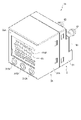
- FIG. 2 is a perspective view showing the outline of the physical quantity measuring device viewed from a direction different from that of FIG. 1;
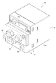
- 1 is an exploded perspective view showing an outline of a physical quantity measuring device according to a first embodiment;
- FIG. 4 is an exploded perspective view showing the outline of the physical quantity measuring device viewed from a direction different from that of FIG. 3 ;
- BRIEF DESCRIPTION OF THE DRAWINGS Sectional drawing which shows the outline of the physical-quantity measuring apparatus of 1st Embodiment.
- FIG. 6 is an enlarged cross-sectional view of region VIII in FIG. 5 ;
- FIG. 10 is a perspective view showing an outline of the physical quantity measuring device viewed from a direction different from that of FIG. 9;
- FIG. 12 is an exploded perspective view showing the outline of the physical quantity measuring device viewed from a direction different from that of FIG. 11; Sectional drawing which shows the outline of the physical-quantity measuring apparatus of 2nd Embodiment.
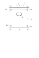
- the front view which shows the outline of the 1st board
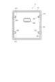
- the front view which shows the outline of the 2nd board
- FIG. 1 is a perspective view showing an outline of a physical quantity measuring device 1 of the present embodiment
- FIG. 2 is a perspective view showing an outline of the physical quantity measuring device 1 viewed from a direction different from that of FIG. 1
- FIG. is an exploded perspective view showing an outline of the physical quantity measuring device 1
- FIG. 4 is an exploded perspective view of the physical quantity measuring device 1 viewed from a direction different from that of FIG. 3, and
- FIG. It is a sectional view showing an outline.
- the physical quantity measuring device 1 of the present embodiment is configured as a differential pressure sensor, more specifically, a small digital differential pressure sensor.
- the physical quantity measuring device 1 includes a first case 2, a second case 3, a circuit board 4, a sensor module 5, a base member 61, a port 62, and a sealing member. 7.
- the first case 2 is formed in a square tubular shape and is a member that houses the sensor module 5 and the like.
- the first case 2 has a first case main body 21 and a fitting portion 22 .
- the first case main body 21 is configured to accommodate the sensor module 5 and the like therein.
- the first case body 21 is provided with a first support portion 211 and a contact portion 212 .
- the first support portions 211 are formed in a columnar shape that protrude toward the second case 3 at the four corners of the first case main body 21 . That is, in this embodiment, four first support portions 211 are provided integrally with the first case main body 21 (see FIG. 6).
- the contact portions 212 are provided at diagonal positions of the first case main body 21 inside the first support portion 211 . That is, in the present embodiment, two contact portions 212 are provided in the first case main body 21 . Each contact portion 212 is in contact with an elastic support member 415, which will be described later.
- openings 214 are formed in the first case main body 21 at positions corresponding to external terminal portions 413 provided on the first substrate 41, which will be described later. Thereby, the external terminal portion 413 is configured to be exposed from the outside of the first case 2 . Furthermore, in the present embodiment, a support structure 215 is provided on the inner peripheral side of the first case main body 21 to support the first substrate 41, which will be described later, in contact therewith.
- the fitting portion 22 is a thin portion on the tip end side of the first case main body 21 .
- the fitting portion 22 is configured to be inserted into and fitted to the inner peripheral side of a second case main body 31 of the second case 3, which will be described later.
- a groove portion G is formed between the fitting portion 22 and a second case main body 31 of the second case 3, which will be described later.
- the second case 3 is formed in a rectangular tubular shape like the first case 2 described above, and is a member that houses a second board 42 of the circuit board 4 and the like, which will be described later.
- the second case 3 has a second case main body 31 and a panel sheet 32 and is fitted to the first case 2 described above. That is, in this embodiment, the second case 3 is attached to the first case 2 .
- the second case main body 31 is configured to accommodate the second substrate 42 and the like therein.
- the second case main body 31 is provided with a second support portion 311 , an inner wall portion 312 and a projection portion 313 .
- the second case body 31 is formed so as to be flush with the first case body 21 when attached to the first case 2 . Furthermore, a panel sheet 32 is attached to the outer surface of the bottom of the second case main body 31 , that is, the front surface of the second case main body 31 . Although not shown, the panel sheet 32 may display the model number, specifications, etc. of the physical quantity measuring device 1 .
- the second support portions 311 are formed in a columnar shape protruding toward the first case 2 near the four corners of the second case main body 31 . That is, in the present embodiment, four second support portions 311 are provided integrally with the second case main body 31 (see FIG. 7). Further, in the present embodiment, the second support portion 311 is formed so as to be arranged inside the first support portion 211 of the first case 2 described above.
- the inner wall portion 312 is a thick portion on the inner surface side of the second case main body 31, and when the first case 2 and the second case 3 are fitted together, the fitting portion 22 of the first case 2 is fitted. Oppose. That is, the groove G described above is formed between the fitting portion 22 of the first case 2 and the inner wall portion 312 of the second case 3 .
- the protrusion 313 is provided so as to protrude from the bottom of the second case main body 31 in a columnar shape, and is configured to come into contact with the second substrate 42 described later.
- circuit board 4 6 is a front view schematically showing the first substrate 41 and the first case 2
- FIG. 7 is a front view schematically showing the second substrate 42 and the second case 3.
- the circuit board 4 has a first board 41 and a second board 42 arranged facing each other.
- the first board 41 is a board housed in the first case main body 21 as described above.
- first cutouts 411 are formed in the first substrate 41 at positions corresponding to the first support parts 211 of the first case body 21 described above, that is, at four corners. That is, the first substrate 41 has four first cutouts 411 .
- the first substrate 41 is provided with a connector receiving portion 412 , an external terminal portion 413 , an internal terminal portion 414 , and an elastic support member 415 .
- the connector receiving portion 412 is arranged on the surface of the first substrate 41 facing the second substrate 42 .
- the connector receiving portion 412 is configured to be connectable to a connector portion 422 of the second substrate 42, which will be described later. As a result, the first substrate 41 and the second substrate 42 are electrically connected by connecting the connector receiving portion 412 and the connector portion 422 .
- the external terminal portion 413 is arranged at a position corresponding to the opening 214 of the first case body 21 and exposed to the outside of the first case body 21 through the opening 214 .
- the external terminal portion 413 can be connected to wiring for external output, wiring for power supply, and the like. That is, the external terminal portion 413 is configured to include an external output terminal portion and a power supply terminal portion.
- the internal terminal portion 414 is arranged at a position corresponding to the connection pin 55 of the sensor module 5 to be described later, and is configured to be connectable with the connection pin 55 .
- the connection pins 55 are connected to the internal terminal portions 414 , thereby electrically connecting the first substrate 41 and the sensor module 5 . That is, in this embodiment, the first substrate 41 and the second substrate 42 are electrically connected to the sensor module 5 .
- the elastic support member 415 is a spring member made of metal and having a Z shape in cross section. In this embodiment, the elastic support member 415 is inserted between the contact portion 212 of the first case main body 21 and the first board 41 of the circuit board 4 (to be described later) at the diagonal position of the first case main body 21 . It is
- the second board 42 is a board housed in the second case main body 31 as described above.
- the second substrate 42 is formed with second notch portions 421 at positions corresponding to the second support portions 311 of the second case body 31 described above, that is, positions near the four corners. there is That is, the second substrate 42 has four second notch portions 421 formed therein. Thereby, when the second board 42 is housed in the second case main body 31 , the second support portion 311 is inserted through the second notch portion 421 .
- a connector portion 422 is provided on the second substrate 42 .
- the connector portion 422 is arranged at a position corresponding to the connector receiving portion 412 of the first board 41 and is connectable with the connector receiving portion 412 .
- the sensor module 5 includes a sensor substrate 51 , a sensor cover 52 , an electronic component 53 , a detection section 54 and connection pins 55 .
- the sensor substrate 51 is a substrate to which components such as the electronic component 53 and the detection section 54 are attached.
- the sensor substrate 51 is arranged to face the first substrate 41 described above.
- the surface of the sensor substrate 51 on the side of the first substrate 41 is covered with a sensor cover 52 .
- the electronic component 53 is arranged on the surface of the sensor substrate 51 facing the first substrate 41 and covered with the sensor cover 52 .
- the electronic component 53 includes a signal converter or the like that converts and adjusts the signal output from the detection section 54 .
- the detection unit 54 is configured to detect the pressure of the fluid to be measured introduced through the port 62 and output a signal corresponding to the pressure to the electronic component 53 .
- the connection pins 55 are arranged at positions corresponding to the internal terminal portions 414 of the first substrate 41 and configured to be connectable to the internal terminal portions 414 .
- the base member 61 is a plate-shaped member and is attached to the rear surface of the first case main body 21 .
- two ports 62 are attached to the base member 61, and holes (not shown) are formed at positions where the ports 62 are attached.
- a filter (not shown) is inserted on the back side of the base member 61, that is, on the first case main body 21 side.
- the port 62 is formed in a tubular shape, and the fluid to be measured is introduced. As a result, the fluid to be measured is introduced into the space inside the first case main body 21 where the detection unit 54 is arranged via the port 62 and the filter described above.
- the physical quantity measuring device 1 is configured as a differential pressure sensor that detects the differential pressure of the fluid to be measured introduced into the two ports 62 .
- the configuration is not limited to the above configuration, and for example, the filter may not be inserted on the back side of the base member 61 .
- FIG. 8 is a cross-sectional view enlarging the VIII region in FIG.
- the sealing member 7 is made of rubber or a resin member and is a member that seals the space between the first case 2 and the second case 3. As shown in FIG. Thereby, when the first case 2 and the second case 3 are fitted together, the space inside the first case 2 and the second case 3 can be sealed.
- the sealing member 7 has a body portion 71 and a sealing portion 72 .
- the body portion 71 has a quadrangular annular shape. Further, in this embodiment, the main body portion 71 is supported by the first substrate 41 . Accordingly, it is not necessary to separately provide a structure for supporting the body portion 71 of the sealing member 7 in the first case 2 . Further, in the present embodiment, the body portion 71 is arranged outside the first support portions 211 provided at the four corners of the first case body 21 . That is, the body portion 71 is positioned by the four first support portions 211 . As a result, when the physical quantity measuring device 1 is assembled, the position of the sealing member 7 can be suppressed from being displaced, so that the physical quantity measuring device 1 can be easily assembled.
- the sealing portion 72 is provided so as to extend from the main body portion 71 to the outer peripheral side, and is arranged in the groove portion G described above. Thereby, the space between the first case 2 and the second case 3 is sealed. Moreover, in the present embodiment, the sealing portion 72 is formed to be thinner than the main body portion 71 . Thereby, the width of the groove portion G for arranging the sealing portion 72 can be reduced. Therefore, the thickness of the walls of the first case 2 and the second case 3 required for disposing the sealing member 7 can be reduced, so that the physical quantity measuring device 1 can be miniaturized.
- the support structure 215 of the first case 2 abuts on the surface of the first substrate 41 facing the sensor module 5 .
- the first substrate 41 is thereby supported by the first case 2 .
- the surface of the first substrate 41 facing the second substrate 42 abuts on the second support portion 311 inserted into the second notch portion 421 of the second substrate 42 . That is, the first substrate 41 is also supported by the second case 3 .
- the first substrate 41 is sandwiched and supported by the support structure 215 of the first case 2 and the second support portion 311 of the second case 3 .
- the first support portion 211 is inserted through the first notch portion 411 of the first substrate 41 .
- the first substrate 41 is positioned by the first support portion 211 of the first case 2 .
- the first substrate 41 is sandwiched between the first case 2 and the second case 3 and positioned and supported by the first case 2 . Therefore, the first substrate 41 can be reliably supported.
- the projection 313 of the second case 3 contacts the surface of the second substrate 42 facing the bottom of the second case 3 .
- the second substrate 42 is thereby supported by the second case 3 .
- the first support portion 211 inserted into the first notch portion 411 of the first substrate 41 abuts on the surface of the second substrate 42 facing the first substrate 41 . That is, the second substrate 42 is also supported by the first case 2 .
- the second substrate 42 is sandwiched and supported by the protrusion 313 of the second case 3 and the first support 211 of the first case 2 .
- the second support portion 311 is inserted through the second notch portion 421 of the second substrate 42 .
- the second substrate 42 is positioned by the second support portion 311 of the second case 3 .
- the second substrate 42 is sandwiched between the first case 2 and the second case 3 and positioned and supported by the second case 3 . Therefore, the second substrate 42 can be reliably supported.
- the elastic support member 415 configured as a spring member is interposed between the contact portion 212 of the first case 2 and the first substrate 41 .
- the first substrate 41 is urged toward the second case 3 by the elastic support member 415 . Therefore, even if there is manufacturing tolerance in the thickness of the first substrate 41 , the tolerance can be absorbed by the elastic support member 415 . Therefore, the first substrate 41 and the second support portion 311 can be reliably brought into contact with each other, so that the first substrate 41 can be reliably supported.
- the first substrate 41 has four first cutouts 411
- the second substrate 42 has four second cutouts 421 .
- the first substrate 41 is supported by a second support portion 311 provided on the second case 3 and a first support portion 211 provided on the first case 2 inserted through the first notch portion 411 . That is, the first substrate 41 is positioned by the first support portion 211 and supported by the second support portion 311 .
- the second substrate 42 is supported by the first support portion 211 provided on the first case 2, with the second support portion 311 provided on the second case 3 inserted into the second notch portion 421. .
- the second substrate 42 is positioned by the second support portion 311 and supported by the first support portion 211 .
- the first board 41 and the second board 42 that constitute the circuit board 4 are positioned by the first support portion 211 and the second support portion 311 that are integrally formed with the first case 2 and the second case 3. , and supported. Therefore, the first substrate 41 and the second substrate 42 can be reliably supported without increasing the number of parts.
- the elastic support member 415 is interposed between the contact portion 212 of the first case 2 and the first substrate 41. Therefore, if the thickness of the first substrate 41 is , the tolerance can be absorbed by the elastic support member 415 . Therefore, the first substrate 41 can be reliably supported.
- first substrate 41 and the second substrate 42 are supported by the first support portion 211 and the second support portion 311 which are formed to protrude in a columnar shape.
- a second substrate 42 can be supported.
- the body portion 71 of the sealing member 7 is positioned by the four first support portions 211. Therefore, when the physical quantity measuring device 1 is assembled, the position of the sealing member 7 can be prevented from shifting. can be suppressed. Therefore, the physical quantity measuring device 1 can be easily assembled. Furthermore, since the sealing portion 72 extending so as to be thinner than the main body portion 71 is arranged in the groove portion G formed between the first case 2 and the second case 3, the groove portion The width of G can be reduced. Therefore, the thickness of the walls of the first case 2 and the second case 3 required for disposing the sealing member 7 can be reduced, so that the physical quantity measuring device 1 can be miniaturized.
- the first case 2 is provided with the support structure 215 that contacts and supports the first substrate 41 .
- the first substrate 41 is sandwiched between the support structure 215 of the first case 2 and the second support portion 311 of the second case 3, so that the first substrate 41 can be reliably supported.
- the second case 3 is provided with the protrusion 313 that contacts and supports the second substrate 42 .
- the second substrate 42 is sandwiched between the first supporting portion 211 of the first case 2 and the projecting portion 313 of the second case 3, so that the second substrate 42 can be reliably supported.
- the first substrate 41A is supported by the second support portion 93A provided on the support member 9A that holds the display portion 8A, and the second substrate 42A is supported by the second support portion. It differs from the first embodiment in that it is positioned by 93A.
- symbol is attached
- the first substrate 41A of the second embodiment includes a first notch portion 411A, a connector receiving portion 412A, an external terminal portion 413A, an internal terminal portion 414A, and the first substrate 41A of the first embodiment described above. and an elastic support member 415A.
- the second substrate 42A has a second notch portion 421A and a connector portion 422A, like the second substrate 42 of the first embodiment described above.
- FIG. 9 is a perspective view showing an outline of the physical quantity measuring device 1A of the present embodiment
- FIG. 10 is a perspective view showing an outline of the physical quantity measuring device 1A viewed from a direction different from that of FIG. 9
- FIG. 12 is an exploded perspective view showing the outline of the physical quantity measuring device 1A
- FIG. 12 is an exploded perspective view of the physical quantity measuring device 1A viewed from a direction different from FIG. 11,
- FIG. 13 is a physical quantity measuring device 1A. It is a sectional view showing an outline.
- the physical quantity measuring device 1A includes a second case 3A, a circuit board 4A, a display section 8A, and a support member 9A.
- the second case 3A is formed in a rectangular cylindrical shape like the second case 3 described above, and is a member that houses a second board 42A of the circuit board 4A, a display section 8A, a support member 9A, and the like, which will be described later.
- the second case 3A has a second case main body 31A and a panel sheet 32A, and is fitted to the first case 2 described above. That is, the second case 3A is attached to the first case 2 in this embodiment.
- the second case main body 31A is configured such that the second substrate 42A, the display section 8A, the support member 9A and the like can be accommodated therein.
- the second case body 31A is formed so as to be flush with the first case body 21 when attached to the first case 2 . Furthermore, an opening 314A is formed in the bottom of the second case main body 31A. Thereby, the user can visually recognize the display unit 8A through the opening 314A.
- a panel sheet 32A is attached to the outer surface of the bottom of the second case main body 31A, that is, to the front surface of the second case main body 31A so as to surround the opening 314A.
- a button operation portion 315A is provided below the opening portion 314A. In this embodiment, three button operation units 315A are provided, and the user can perform various operations by operating the button operation units 315A.
- the display unit 8A is a liquid crystal display (LCD) that digitally displays the differential pressure detected by the sensor module 5, and is electrically connected to the second board 42A of the circuit board 4A. In the present embodiment, it is fitted into a display holding recess 92A of a support member 9A, which will be described later, and held by being sandwiched between display holding claws 94A. As described above, the differential pressure digitally displayed on the display section 8A is configured to be visible through the opening 314A of the second case main body 31A.
- LCD liquid crystal display
- the support member 9A is a member that is housed in the second case main body 31A and holds the display section 8A. Furthermore, in this embodiment, the support member 9A is configured to position the second substrate 42A and support the first substrate 41A.
- the support member 9A includes a support member body portion 91A, a display holding concave portion 92A, a second support portion 93A, and a display holding claw portion 94A.
- the support member body portion 91A is formed in a substantially rectangular parallelepiped shape and arranged between the display portion 8A and the second substrate 42A.
- a display holding recessed portion 92A recessed according to the shape of the display portion 8A is formed on the surface of the support member body portion 91A on the side of the display portion 8A.
- two display holding claw portions 94A extending toward the display portion 8A are formed on the outer peripheral side of the support member main body portion 91A.
- the support member body portion 91A is configured to hold the display portion 8A by fitting the display portion 8A into the display holding concave portion 92A and holding the display portion 8A between the display holding claw portions 94A. ing.
- the display holding concave portion 92A and the display holding claw portion 94A constitute the display holding portion of the present invention.
- a second support portion 93A protruding toward the first case 2 is provided on the second substrate 42A side of the support member body portion 91A.
- the second support portions 93A are provided so as to protrude toward the first case 2 in the vicinity of the four corners of the support member 9A.
- the second support portion 93A has a claw-shaped support portion 931A and a columnar support portion 932A.
- the claw-shaped support portion 931A is formed in a claw shape integrally with the support member 9A.
- two claw-shaped support portions 931A are provided.
- the columnar support portion 932A is formed in a columnar shape integrally with the support member 9A.
- two columnar support portions 932A are provided. That is, in this embodiment, four second support portions 93A are provided.
- FIG. 14 is a front view showing an outline of the first substrate 41 and the first case 2
- FIG. 15 is a front view showing an outline of the second substrate 42A and the second case 3A.
- the supporting structure 215 of the first case 2 abuts on the surface of the first substrate 41A facing the sensor module 5.
- the first substrate 41A is thereby supported by the first case 2 .
- the surface of the first substrate 41A facing the second substrate 42A abuts on the second support portion 93A inserted through the second notch portion 421A of the second substrate 42A. That is, the first substrate 41A is also supported by the support member 9A housed in the second case 3A. Thus, the first substrate 41A is sandwiched and supported by the support structure 215 of the first case 2 and the second support portion 93A of the support member 9A. Further, the first support portion 211 is inserted through the first notch portion 411A of the first substrate 41A. As a result, the first substrate 41A is positioned by the first support portion 211 of the first case 2 . Thus, in this embodiment, the first substrate 41A is sandwiched between the first case 2 and the support member 9A, and is positioned and supported by the first case 2. As shown in FIG. Therefore, the first substrate 41A can be reliably supported.
- the second substrate 42A contacts the surface of the support member 9A facing the support member main body 91A with the surface of the support member main body 91A opposite to the surface on which the display holding recess 92A is formed. Thereby, the second substrate 42A is supported by the support member 9A. Furthermore, the first support portion 211 inserted into the first notch portion 411A of the first substrate 41A abuts on the surface of the second substrate 42A facing the first substrate 41A. That is, the second substrate 42A is also supported by the first case 2. As shown in FIG. In this manner, the second substrate 42A is sandwiched and supported by the support member 9A and the first support portion 211 of the first case 2 .
- the second support portion 93A is inserted through the second notch portion 421A of the second substrate 42A.
- the second substrate 42A is positioned by the second support portion 93A of the support member 9A.
- the second substrate 42A is sandwiched between the first case 2 and the support member 9A, and is positioned and supported by the support member 9A. Therefore, the second substrate 42A can be reliably supported.
- the first substrate 41A is such that the first supporting portion 211 provided on the first case 2 is inserted into the first notch portion 411A, and the second supporting portion 93A provided on the supporting member 9A. Supported by That is, the first substrate 41A is positioned by the first support portion 211 and supported by the second support portion 93A. Similarly, the second substrate 42A is supported by the first support portion 211 provided in the first case 2, with the second support portion 93A provided on the support member 9A inserted through the second notch portion 421A. That is, the second substrate 42A is positioned by the second support portion 93A and supported by the first support portion 211.
- the first board 41A and the second board 42A that constitute the circuit board 4A are positioned by the first support part 211 and the second support part 93A integrally formed with the first case 2 and the support member 9A, and supported. Therefore, the first substrate 41A and the second substrate 42A can be reliably supported without increasing the number of parts.
- the elastic support members 415 and 415A that contact the contact portion 212 of the first case 2 are Z-shaped in cross section and configured as spring members, but are not limited to this.
- the elastic support member may be configured as a coil spring member as long as it is configured to be able to bias the first substrate toward the second case.
- the present invention also includes a mode in which the elastic support member is not provided.
- first substrates 41 and 41A are housed in the first case 2 in each of the embodiments described above, the present invention is not limited to this.
- the first substrate may be housed in the second case.
- the second substrates 42, 42A were housed in the second cases 3, 3A, but the present invention is not limited to this.
- the second substrate may be housed in the first case.
- the first support portion 211 and the second support portion 311 are formed in a columnar shape, but are not limited to this.
- the first support part and the second support part may have a prism shape, or may have a tubular shape with a hollow interior.
- the second support portion 93A is formed in a claw shape or columnar shape, but is not limited to this.
- the first support part and the second support part may have a prism shape, or may have a tubular shape with a hollow interior.
- first support portions 211 and four second support portions 311 and 93A are provided, but the present invention is not limited to this.
- five or more first support portions and second support portions may be provided, or three or less may be provided, or a plurality of each may be provided.
- the sealing member 7 is configured to include the main body portion 71 formed in a rectangular ring shape and the sealing portion 72 extending outward from the main body portion 71.
- the sealing member may be composed only of the main body portion arranged in the groove formed between the first case and the second case.
- the physical quantity measuring device 1 is configured as a differential pressure sensor that detects the differential pressure of the fluid to be measured introduced into the two ports 62, but is not limited to this.
- the physical quantity measuring device may include one port and be configured as a pressure sensor that detects the pressure of the fluid to be measured introduced into the port, or as a temperature sensor that detects the temperature of the fluid to be measured. Any physical quantity of the fluid to be measured may be detected.
- the first substrates 41 and 41A have the first notch portions 411 and 411A formed at the four corners, but the present invention is not limited to this.
- the first substrate is formed with a plurality of first notches near the central portion, and the first support portion of the first case is inserted through the first notches.
- the position and number of the first notches in the first substrate can be arbitrary.
- the second substrates 42 and 42A have the second cutouts 421 and 421A near the four corners, but the present invention is not limited to this.
- the second substrate is formed with a plurality of second notches near the central portion, and the second support portion of the second case is inserted through the second notches.
- the position and number of the second notches in the second substrate can be arbitrary.
Landscapes
- Physics & Mathematics (AREA)
- General Physics & Mathematics (AREA)
- Chemical & Material Sciences (AREA)
- Analytical Chemistry (AREA)
- Fluid Mechanics (AREA)
- Measuring Fluid Pressure (AREA)
Priority Applications (3)
| Application Number | Priority Date | Filing Date | Title |
|---|---|---|---|
| EP22795611.7A EP4332532A4 (en) | 2021-04-28 | 2022-04-18 | DEVICE FOR MEASURING PHYSICAL QUANTITIES |
| JP2023517450A JP7606600B2 (ja) | 2021-04-28 | 2022-04-18 | 物理量測定装置 |
| KR1020237039997A KR20230172029A (ko) | 2021-04-28 | 2022-04-18 | 물리량 측정 장치 |
Applications Claiming Priority (2)
| Application Number | Priority Date | Filing Date | Title |
|---|---|---|---|
| JP2021-075983 | 2021-04-28 | ||
| JP2021075983 | 2021-04-28 |
Publications (1)
| Publication Number | Publication Date |
|---|---|
| WO2022230698A1 true WO2022230698A1 (ja) | 2022-11-03 |
Family
ID=83847023
Family Applications (1)
| Application Number | Title | Priority Date | Filing Date |
|---|---|---|---|
| PCT/JP2022/017982 Ceased WO2022230698A1 (ja) | 2021-04-28 | 2022-04-18 | 物理量測定装置 |
Country Status (4)
| Country | Link |
|---|---|
| EP (1) | EP4332532A4 (https=) |
| JP (1) | JP7606600B2 (https=) |
| KR (1) | KR20230172029A (https=) |
| WO (1) | WO2022230698A1 (https=) |
Citations (9)
| Publication number | Priority date | Publication date | Assignee | Title |
|---|---|---|---|---|
| JPS5552890U (https=) * | 1978-09-21 | 1980-04-09 | ||
| JPH0488834U (https=) * | 1991-05-27 | 1992-08-03 | ||
| JPH062765U (ja) * | 1992-06-22 | 1994-01-14 | 株式会社東芝 | Lcdの取付構造 |
| JP2004281870A (ja) * | 2003-03-18 | 2004-10-07 | Omron Corp | 基板支持装置 |
| WO2007004313A1 (ja) * | 2005-06-30 | 2007-01-11 | Sunx Limited | 圧力センサ |
| JP2009260051A (ja) * | 2008-04-17 | 2009-11-05 | Yokogawa Electric Corp | 電子機器 |
| JP2014225497A (ja) * | 2013-05-15 | 2014-12-04 | Necカシオモバイルコミュニケーションズ株式会社 | 携帯端末装置 |
| JP2017211260A (ja) | 2016-05-25 | 2017-11-30 | 長野計器株式会社 | 物理量測定装置 |
| CN112254873A (zh) * | 2020-09-10 | 2021-01-22 | 上海三高计算机中心股份有限公司 | 一种用于监测管网水锤的低功耗压力数据记录仪 |
Family Cites Families (4)
| Publication number | Priority date | Publication date | Assignee | Title |
|---|---|---|---|---|
| JPS60113687U (ja) * | 1984-01-09 | 1985-08-01 | 日本電気株式会社 | 回路基板の固定構造 |
| JPH0530119Y2 (https=) * | 1987-05-27 | 1993-08-02 | ||
| US20180348030A1 (en) | 2017-06-01 | 2018-12-06 | Kita Sensor Tech. Co., Ltd. | Sensor with a gas flow sensing chip for measurement of flow rate of a gas flowing through a gas conduit |
| CN210638759U (zh) | 2019-12-16 | 2020-05-29 | 开封青天伟业流量仪表有限公司 | 一种多用途流量仪表转换器 |
-
2022
- 2022-04-18 JP JP2023517450A patent/JP7606600B2/ja active Active
- 2022-04-18 KR KR1020237039997A patent/KR20230172029A/ko active Pending
- 2022-04-18 WO PCT/JP2022/017982 patent/WO2022230698A1/ja not_active Ceased
- 2022-04-18 EP EP22795611.7A patent/EP4332532A4/en active Pending
Patent Citations (9)
| Publication number | Priority date | Publication date | Assignee | Title |
|---|---|---|---|---|
| JPS5552890U (https=) * | 1978-09-21 | 1980-04-09 | ||
| JPH0488834U (https=) * | 1991-05-27 | 1992-08-03 | ||
| JPH062765U (ja) * | 1992-06-22 | 1994-01-14 | 株式会社東芝 | Lcdの取付構造 |
| JP2004281870A (ja) * | 2003-03-18 | 2004-10-07 | Omron Corp | 基板支持装置 |
| WO2007004313A1 (ja) * | 2005-06-30 | 2007-01-11 | Sunx Limited | 圧力センサ |
| JP2009260051A (ja) * | 2008-04-17 | 2009-11-05 | Yokogawa Electric Corp | 電子機器 |
| JP2014225497A (ja) * | 2013-05-15 | 2014-12-04 | Necカシオモバイルコミュニケーションズ株式会社 | 携帯端末装置 |
| JP2017211260A (ja) | 2016-05-25 | 2017-11-30 | 長野計器株式会社 | 物理量測定装置 |
| CN112254873A (zh) * | 2020-09-10 | 2021-01-22 | 上海三高计算机中心股份有限公司 | 一种用于监测管网水锤的低功耗压力数据记录仪 |
Non-Patent Citations (1)
| Title |
|---|
| See also references of EP4332532A4 |
Also Published As
| Publication number | Publication date |
|---|---|
| JPWO2022230698A1 (https=) | 2022-11-03 |
| EP4332532A1 (en) | 2024-03-06 |
| KR20230172029A (ko) | 2023-12-21 |
| JP7606600B2 (ja) | 2024-12-25 |
| EP4332532A4 (en) | 2025-06-11 |
Similar Documents
| Publication | Publication Date | Title |
|---|---|---|
| CN101839785B (zh) | 传感器 | |
| JP2006163006A (ja) | カメラモジュール固定構造及びその固定方法並びにそれを用いた携帯端末 | |
| JP2020085720A (ja) | センサアッシーおよび物理量測定装置 | |
| WO2022230698A1 (ja) | 物理量測定装置 | |
| WO2022230699A1 (ja) | 物理量測定装置 | |
| JP7568472B2 (ja) | パネルモジュールユニット | |
| KR20100028765A (ko) | 백라이트 어셈블리 및 이의 조립 방법 | |
| JP4820588B2 (ja) | 圧力センサ | |
| EP4179887A1 (en) | Body unit of aerosol generation device, aerosol generation device, and non-combustion-type inhaler | |
| JP4790032B2 (ja) | センサ | |
| CN119223498B (zh) | 一种压力传感器 | |
| JP6255288B2 (ja) | センサモジュール | |
| JPH07286925A (ja) | 圧力センサーとこの圧力センサーを用いたガス供給システム及びガス漏れ検出方法 | |
| CN218416520U (zh) | 摄像装置 | |
| JP2000304640A (ja) | 静電容量形圧力センサユニット | |
| JP4808102B2 (ja) | 光路変換中継光コネクタ | |
| JP2000292288A (ja) | 圧力センサ | |
| CN205561864U (zh) | 传感器 | |
| JPH11166874A (ja) | 静電容量型圧力センサユニット | |
| CN109390765B (zh) | 电子设备 | |
| JP2928748B2 (ja) | 圧力センサ | |
| JP5997686B2 (ja) | 物理量測定センサ | |
| JP2001337629A (ja) | 表示器及び表示器一体型の圧力センサ | |
| JP6030539B2 (ja) | センサモジュール及び物理量測定センサ | |
| JP4790033B2 (ja) | センサ |
Legal Events
| Date | Code | Title | Description |
|---|---|---|---|
| 121 | Ep: the epo has been informed by wipo that ep was designated in this application |
Ref document number: 22795611 Country of ref document: EP Kind code of ref document: A1 |
|
| WWE | Wipo information: entry into national phase |
Ref document number: 2023517450 Country of ref document: JP |
|
| ENP | Entry into the national phase |
Ref document number: 20237039997 Country of ref document: KR Kind code of ref document: A |
|
| WWE | Wipo information: entry into national phase |
Ref document number: 1020237039997 Country of ref document: KR |
|
| WWE | Wipo information: entry into national phase |
Ref document number: 2022795611 Country of ref document: EP |
|
| NENP | Non-entry into the national phase |
Ref country code: DE |
|
| ENP | Entry into the national phase |
Ref document number: 2022795611 Country of ref document: EP Effective date: 20231128 |