WO2022230421A1 - 圧抜きプラグ及びこれを用いた油圧配管の圧抜き方法 - Google Patents
圧抜きプラグ及びこれを用いた油圧配管の圧抜き方法 Download PDFInfo
- Publication number
- WO2022230421A1 WO2022230421A1 PCT/JP2022/012006 JP2022012006W WO2022230421A1 WO 2022230421 A1 WO2022230421 A1 WO 2022230421A1 JP 2022012006 W JP2022012006 W JP 2022012006W WO 2022230421 A1 WO2022230421 A1 WO 2022230421A1
- Authority
- WO
- WIPO (PCT)
- Prior art keywords
- poppet
- hole
- coupler
- hydraulic
- pressing
- Prior art date
- Legal status (The legal status is an assumption and is not a legal conclusion. Google has not performed a legal analysis and makes no representation as to the accuracy of the status listed.)
- Ceased
Links
Images




Classifications
-
- F—MECHANICAL ENGINEERING; LIGHTING; HEATING; WEAPONS; BLASTING
- F16—ENGINEERING ELEMENTS AND UNITS; GENERAL MEASURES FOR PRODUCING AND MAINTAINING EFFECTIVE FUNCTIONING OF MACHINES OR INSTALLATIONS; THERMAL INSULATION IN GENERAL
- F16K—VALVES; TAPS; COCKS; ACTUATING-FLOATS; DEVICES FOR VENTING OR AERATING
- F16K24/00—Devices, e.g. valves, for venting or aerating enclosures
-
- F—MECHANICAL ENGINEERING; LIGHTING; HEATING; WEAPONS; BLASTING
- F16—ENGINEERING ELEMENTS AND UNITS; GENERAL MEASURES FOR PRODUCING AND MAINTAINING EFFECTIVE FUNCTIONING OF MACHINES OR INSTALLATIONS; THERMAL INSULATION IN GENERAL
- F16L—PIPES; JOINTS OR FITTINGS FOR PIPES; SUPPORTS FOR PIPES, CABLES OR PROTECTIVE TUBING; MEANS FOR THERMAL INSULATION IN GENERAL
- F16L37/00—Couplings of the quick-acting type
- F16L37/28—Couplings of the quick-acting type with fluid cut-off means
- F16L37/38—Couplings of the quick-acting type with fluid cut-off means with fluid cut-off means in only one of two pipe-end fittings
-
- F—MECHANICAL ENGINEERING; LIGHTING; HEATING; WEAPONS; BLASTING
- F16—ENGINEERING ELEMENTS AND UNITS; GENERAL MEASURES FOR PRODUCING AND MAINTAINING EFFECTIVE FUNCTIONING OF MACHINES OR INSTALLATIONS; THERMAL INSULATION IN GENERAL
- F16L—PIPES; JOINTS OR FITTINGS FOR PIPES; SUPPORTS FOR PIPES, CABLES OR PROTECTIVE TUBING; MEANS FOR THERMAL INSULATION IN GENERAL
- F16L55/00—Devices or appurtenances for use in, or in connection with, pipes or pipe systems
-
- F—MECHANICAL ENGINEERING; LIGHTING; HEATING; WEAPONS; BLASTING
- F16—ENGINEERING ELEMENTS AND UNITS; GENERAL MEASURES FOR PRODUCING AND MAINTAINING EFFECTIVE FUNCTIONING OF MACHINES OR INSTALLATIONS; THERMAL INSULATION IN GENERAL
- F16L—PIPES; JOINTS OR FITTINGS FOR PIPES; SUPPORTS FOR PIPES, CABLES OR PROTECTIVE TUBING; MEANS FOR THERMAL INSULATION IN GENERAL
- F16L55/00—Devices or appurtenances for use in, or in connection with, pipes or pipe systems
- F16L55/07—Arrangement or mounting of devices, e.g. valves, for venting or aerating or draining
Definitions
- the present invention relates to a depressurization plug that is connected to a coupler of hydraulic piping to discharge hydraulic oil inside the hydraulic piping, and a method of depressurizing the hydraulic piping using the same.
- Patent Document 1 discloses a residual pressure relief jig for self-sealing couplings.
- the jig includes a tubular member, a lid-shaped member, a rod, and a discharge pipe.
- the tubular member is connectable to a plug and a socket, respectively, in the self-sealing coupling, and is coupled to the tubular member and the plug using a portion of a locking mechanism provided on the plug or the socket. Alternatively, the connection state with the socket can be locked.
- the lid-shaped member is fixed to the tip of the tubular member, and a screw hole is formed in the central portion of the lid-shaped member along the axis of the tubular member.
- the rod has an external thread that can be screwed into the threaded hole so as to move in the direction of the axis, and an outer end that can be rotated.
- the residual pressure discharge pipe communicates with the inside of the tubular member.
- the rod advances in the axial direction with respect to the lid-shaped member while the cylindrical member is connected to the plug or the socket, thereby moving the valve body inside the plug or the socket. Push to open. As a result, the hydraulic fluid in the hydraulic pipe can be discharged through the residual pressure discharge pipe.
- a pressure relief plug that connects to the coupler of a hydraulic line having a coupler to allow hydraulic fluid inside the hydraulic line to drain.
- the coupler includes a coupler body and a poppet.
- the coupler main body is formed with a hydraulic fluid flow path, which is a flow path for the hydraulic fluid.
- the poppet is arranged inside the coupler body so as to be relatively displaceable with respect to the coupler body between a closed position and an open position, which is a position inside the hydraulic pipe relative to the closed position. The poppet closes the hydraulic fluid flow path in the closed position and opens the hydraulic fluid flow path in the open position.
- the poppet is held at the closed position within the coupler body and is allowed to be displaced from the closed position to the open position by being pressed in a pressing direction toward the inside of the hydraulic pipe.
- the depressurization plug includes a pipe connecting member and a poppet pressing member.
- the pipe connection member can be detachably connected to the coupler in a connection direction parallel to the pressing direction, and in a connected state connected to the coupler body, the pipe connection member can be connected in the connection direction from the coupler body. Extend.
- the poppet pressing member is held by the pipe connecting member so as to be able to press the poppet in the pressing direction in the connected state.
- the pipe connection member has both ends in the connection direction, one of which is a coupler connection end connected to the coupler main body, and the other of which is an outer end.
- a threaded hole and an oil reservoir are formed inside the pipe connecting member.
- the threaded hole extends along the connection direction from the outer end portion toward the coupler connection end portion, and has an inner peripheral surface formed with a female thread. It has a concave shape that opens toward you.
- the poppet pressing member has a shape that allows it to be inserted through the screw hole, and has an outer peripheral surface formed with a male thread that can be screwed with the female thread.
- the poppet pressing member is formed with a main communication hole and a sub communication hole extending in the connection direction.
- the auxiliary communication hole communicates the oil reservoir with the main communication hole in a state in which the poppet pressing member presses the poppet to displace the poppet to the open position. is allowed to flow out toward the outer end portion of the pipe connection member through the secondary communication hole and the main communication hole.
- FIG. 1 is a cross-sectional view of a pressure relief plug and a hydraulic line coupler according to a first embodiment of the present invention, wherein the pressure relief plug is connected to the coupler and presses against a poppet within the coupler;
- FIG. 4 is a cross-sectional view of the pressure relief plug according to the first embodiment, wherein the pressure relief plug is removed from the coupler and the poppet pressing member of the pressure relief plug is in a released position;
- FIG. FIG. 4 is a perspective view of the pressure release plug according to the first embodiment, viewed from above;
- FIG. 4 is a perspective view of the depressurization plug according to the first embodiment, viewed from below;
- FIG. 4 is a cross-sectional view of a depressurization plug according to a modification of the first embodiment; It is the perspective view which looked at the said depressurization plug which concerns on the said modification from the upper side. It is the perspective view which looked at the said depressurization plug which concerns on the said modification from the lower side.
- Fig. 10 is a cross-sectional view of a depressurization plug according to a second embodiment of the present invention, with a poppet depressing member of said depressurization plug in a depressing position;
- FIG. 8 is a cross-sectional view of the pressure relief plug according to the second embodiment, with the poppet pressing member in a released position;
- FIG. 11 is a perspective view of the pressure relief plug according to the second embodiment as viewed from above;
- FIG. 11 is a perspective view of the pressure release plug according to the second embodiment as viewed from below;
- the pressure relief plug 20 is used in hydraulic lines of various machines.
- An example of such a machine is a large dismantling machine, and the large dismantling machine includes, for example, a lower running body, an upper revolving body, and an attachment.
- the upper rotating body includes, for example, a hydraulic oil tank and a hydraulic pressure source.
- Such attachments include, for example, lower booms, boom foot cylinders, arms, arm cylinders and crushers.
- Hydraulic piping including a quick coupling is used for such a detachable attachment, and residual pressure tends to remain inside the hydraulic piping. The residual pressure may act as a resistance when reconnecting the hydraulic piping, making the connection difficult.
- the pressure release plug 20 enables release of residual pressure as described above.
- the pressure relief plug 20 is used in the hydraulic piping 10 shown in FIG.
- the hydraulic piping 10 includes a piping body 12 and a coupler 14 .
- the coupler 14 includes a coupler body 15 and a poppet 16, and together with the pressure relief plug 20 constitutes a pressure relief device.
- the coupler body 15 is attached to the end of the piping body 12 .
- the coupler main body 15 is formed with a hydraulic oil passage 17 which is a passage for the hydraulic oil.
- the coupler body 15 according to this embodiment includes a body member 15a and a receiving member 15b.
- the main body member 15a has a tubular shape surrounding the hydraulic oil passage 17.
- the receiving member 15b has a tubular shape with an inner diameter substantially equal to the outer diameter of the main body member 15a, and is fitted on the end of the main body member 15a on the tip side (upper side in FIG. 1). , thereby defining a receiving space located distally of the body member 15a, the receiving space receiving the pressure relief plug 20 fitted therein.
- the poppet 16 is provided inside the coupler body 15 so that it can be displaced relative to the coupler body 15 between the open position and the closed position shown in FIG. placed.
- the poppet 16 blocks the hydraulic fluid flow path 17 in the closed position shown in FIG.
- the open position is a position inside (lower in FIG. 1) the hydraulic pipe 10 than the closed position, and the poppet 16 opens the hydraulic fluid passage 17 at the open position to allow the hydraulic fluid to flow. do.
- the coupler main body 15 further includes a plurality of poppet holding portions 15c.
- the plurality of poppet holding portions 15c protrude inward from the inner peripheral surface of the body member 15a.
- the poppet 16 is inserted axially (in the vertical direction in FIG. 1) into the space surrounded by the tip end portions of the plurality of poppet holding portions 15c, so that the poppet 16 is axially inserted into the coupler main body 15. It is held by the plurality of poppet holding portions 15c so as to be movable between the closed position and the open position along the line.
- the coupler 14 further includes a coil spring (not shown).
- the coil spring is interposed between the poppet 16 and the plurality of poppet holding portions 15c in a compressed state, thereby moving the poppet 16 from the open position to the closed position (that is, the tip end). side).
- the poppet 16 is held in the closed position where the valve body portion 16a and the valve seat portion 15s are in contact with each other, and is pushed toward the inside of the hydraulic pipe 10 (downward in FIG. 1). ), the spring is allowed to be displaced from the closed position to the open position while being elastically deformed.
- the depressurization plug 20 constitutes a depressurization device together with the coupler 14 .
- the depressurization plug 20 is connected to the coupler body 15 so that the working oil inside the hydraulic pipe 10 can be easily discharged.
- the depressurization plug 20 includes a pipe connection member 21 and a poppet pressing member 28 .
- the pipe connection member 21 is detachably connected to the coupler main body 15 of the hydraulic pipe 10 in the connection direction. In this connected state in which the pipe connection member 21 is connected to the coupler main body 15, the pipe connection member 21 extends from the coupler main body 15 in the connection direction.
- the connection direction is a direction parallel to the pressing direction, which is the axial direction in this embodiment and the vertical direction in FIG.
- the pipe connection member 21 is a male type that can be fitted into the receiving space of the coupler main body 15 .
- the pipe connecting member 21 has a fitting outer peripheral surface 21a that can be fitted with the inner peripheral surface 15d of the receiving member 15b.
- the inner peripheral surface 15d is provided with a female thread
- the outer peripheral surface 21a is provided with a male thread that can be screwed with the female thread.
- the outer peripheral surface 21a constitutes an operated surface 21b that can receive a rotational operation
- the operated surface 21b is It has a shape that can be rotated by a jig (not shown), for example, a shape other than a circle, such as a hexagon.
- the coupler 14 is a so-called quick coupler
- the outer peripheral surface 21a is given a shape suitable for the quick coupler.
- An oil reservoir 22 is formed in the pipe connection member 21 .
- the oil reservoir 22 is formed inside the coupler connection end portion of the pipe connection member 21 and is recessed so as to open toward the coupler 14 .
- the coupler connection end is one end (lower end in FIG. 1) of both ends of the pipe connection member 21 in the connection direction, and the other end (upper end) is outside. at the end.
- a threaded hole 21c is further formed in the pipe connection member 21.
- the threaded hole 21c extends from the outer end portion toward the coupler body 15 along the connection direction, and in this embodiment, extends along the central axis of the pipe connection member 21 so as to be continuous with the oil reservoir 22. Extend.
- a female thread is formed on the inner peripheral surface of the pipe connection member 21 surrounding the screw hole 21c.
- the poppet pressing member 28 is held by the pipe connection member 21 so as to be relatively displaceable in the connection direction with respect to the pipe connection member 21, and the pipe connection member 21 is connected to the coupler 14. By displacing relative to the piping connection member 21 in the pressing direction, the poppet 16 can be pressed in the pressing direction and displaced to the closed position as shown in FIG.
- the poppet pressing member 28 includes a pressing member main body, a sealing member 26 and a restraining member 27 , and the pressing member main body includes a first main body member 23 and a second main body member 24 .
- the first body member 23 has a shape that allows it to be inserted into the threaded hole 21c of the pipe connection member 21 while being screwed.
- the first body member 23 has a threaded outer peripheral surface 23c, and a male thread is formed on the threaded outer peripheral surface 23c, and the male thread can be screwed into the female thread of the threaded hole 21c. It is possible.
- the first main body member 23 further includes an operated surface 23e located on the tip side (upper side in FIG. 1) of the screwing outer peripheral surface 23c, and the operated surface 23e is rotated to rotate the first main body member.
- the first body member 23 can be relatively displaced in the connection direction with respect to the pipe connection member 21 by rotating the entirety of the pipe connection member 21 relative to the pipe connection member 21 .
- the first body member 23 is thereby capable of pressing the poppet 16 of the coupler 14 in the pressing direction to displace the poppet 16 from the closed position to the open position shown in FIG.
- the inside of the hydraulic pipe 10 and the oil reservoir 22 can be communicated with each other.
- the first body member 23 is formed with a first body hole 23a, a plurality of secondary communication holes 23b, and screw holes 23d.
- the first body hole 23 a extends in the connection direction along the central axis of the first body member 23 and opens toward the poppet 16 .
- the plurality of sub-communication holes 23b are formed at the end (lower end in FIG. 1) of the first main body member 23 in the connecting direction, which is closer to the poppet 16. It is arranged so as to surround the hole 23a, and communicates the first main body hole 23a and the oil reservoir 22 in the radial direction.
- the radial direction is a direction orthogonal to the connection direction (axial direction).
- the plurality of sub-communication holes 23b are a pair of communication holes arranged in a straight line. may contain. Alternatively, only a single secondary communication hole may be formed in the first body member 23 .
- the screw hole 23d is located on the distal end side of the first body hole 23a and communicates with the first body hole 23a in the connection direction (axial direction).
- a female thread is engraved on the inner peripheral surface of the first body member 23 surrounding the screw hole 23d.
- the second main body member 24 can be connected to the first main body member 23 in the connection direction (axial direction), thereby forming the pressing member main body together with the first main body member 23 .
- the second body member 24 includes a connecting portion 24d and an operated portion 24e arranged in the connecting direction.
- the connecting portion 24d has an outer peripheral surface on which a male thread is formed, and the male thread can be screwed with the female thread of the threaded hole 23d of the first body member 23.
- the second main body member 24 is detachably connected to the first main body member 23 in a state of being located on the distal end side of the first main body member 23 .
- the operated portion 24e is located on the distal end side of the connecting portion 24d.
- the operated portion 24e has an outer diameter larger than that of the connecting portion 24d, and can be rotated.
- the second main body member 24 is formed with a second main body hole 24a, a sealing member accommodation hole 25, and a screw hole 24f. They are lined up in the above connection direction.
- the second body hole 24a communicates with the first body hole 23a in the connection direction in a state where the first and second body members 23 and 24 are connected to each other. It constitutes a hole (a part of the main communication hole in this embodiment).
- the main communication hole is a hole extending in the connection direction (the vertical direction in FIG. 1) so as to pass through the poppet pressing member 28 in the connection direction.
- the sealing member accommodating hole 25 is located on the distal end side of the second main body hole 24a and accommodates the sealing member 26 therein. Specifically, the sealing member receiving hole 25 has a diameter capable of receiving the sealing member 26 and larger than the diameter of the second main body hole 24a.
- the sealing member 26 is housed in the sealing member housing hole 25 of the second body member 24 so as to be movable in the connecting direction between the sealing position and the open position.
- the sealing member 26 seals the outer opening 24b at the sealing position. It is an opening on the tip side (the side opposite to the poppet 16; the upper side in FIG. 1).
- the sealing member 26 according to this embodiment has a spherical shape with a larger diameter than the diameter of the second main body hole 24a including the outer opening 24b.
- the outside opening 24b is sealed by contacting the periphery of the opening 24b along the entire periphery.
- the open position is a position closer to the distal end than the sealed position.
- the sealing member 26 opens the outer opening 24b by moving away from the outer opening 24b toward the tip side.
- the shape of the sealing member 26 is not limited to a spherical shape, and can be movable between the sealing position and the open position, and can seal the outer opening 24b at the sealing position. Any shape is acceptable.
- the sealing member 26 may include a hemispherical portion that can come into contact with the periphery of the outer opening 24b and a columnar portion located on the distal side of the hemispherical portion.
- the second body hole 24a preferably has a smaller diameter than the first body hole 23a. This allows the diameter of the outer opening 24b to be reduced, thereby reducing the diameter of the sealing member 26 required to seal the outer opening 24b. Moreover, it is preferable that the peripheral edge of the outer opening 24b in the second body member 24 is tapered so as to be in close contact with the sealing member 26 with higher precision.
- the restraint member 27 is screwed to the second body member 24 so as to be displaceable relative to the second body member 24 in the connection direction between the restraint position and the restraint release position.
- the restraining member 27 extends from the opposite side (upper side in FIG. 1) of the body hole (in this embodiment, the first and second body holes 23a and 24a) as shown in FIG.
- the sealing member 26 is constrained in the sealing position.
- the restraint release position is a position on the distal end side (upper side in FIG. 1) of the restraint position.
- the restraint of the sealing member 26 is released so as to allow the movement to.
- a restraining concave portion 27c is formed at an end portion (lower end portion in FIG.
- the constraining recess 27c has a conical shape with a diameter that decreases as the distance from the sealing member 26 increases, allowing the sealing member 26 (which is spherical in this embodiment) to fit into the constraining recess 27c. .
- the restraint member 27 has an outer peripheral surface 27d with a male thread.
- the threaded hole 24f of the second body member 24 has a female thread that can be screwed with the male thread, and the restraint member 27 is screwed into the threaded hole 24f.
- the screwing causes the restraint member 27 to be displaced in the connection direction with respect to the second body member 24 as the restraint member 27 is rotated, thereby moving the restraint member 27 to the restraint position. It is possible to move to and from the restraint release position.
- a release hole is formed inside the restraint member 27, and the release hole constitutes the main communication hole together with the first and second body holes 23a and 24a and the sealing member accommodation hole 25.
- the discharge hole according to this embodiment is composed of a first discharge hole 27a and a second discharge hole 27b.
- the first discharge hole 27a is the distal end of the restraint member 27, that is, the end of the restraint member 27 opposite to the first and second main body holes 23a and 24a in the connecting direction. , to a position on the front side (front end side) of the restraint recess 27c in the connection direction.
- the second discharge hole 27b extends in the radial direction so as to be connected to the end of the first discharge hole 27a on the side closer to the sealing member 26 (lower side in FIG. 1). 27a and the space radially outside the restraint member 27 are communicated in the radial direction.
- the first and second discharge holes 27a and 27b allow the movement of the sealing member 26 to the open position with the restraint member 27 at the restraint release position. Hydraulic oil that has flowed into the sealing member accommodation hole 25 through the first and second main body holes 23a, 24a further passes through the first and second discharge holes 27a, 27b to the tip end of the restraining member 27 (in FIG. 1, upper end) to the outside of the restraining member 27 along the connecting direction.
- the second discharge hole 27b shown in FIG. 1 is composed of a single radially extending through hole, it may be composed of, for example, a plurality of through holes extending in different directions.
- the main communication hole according to the present invention may have a shape that extends in the connection direction as a whole and allows hydraulic oil to be discharged in the connection direction. does not exclude those that partially include a portion extending to In other words, the main communication hole should extend in the connection direction as a whole so as to allow the hydraulic oil in the oil reservoir 22 to be discharged to the outside of the poppet pressing member 28 along the connection direction. good.
- the attachment incorporating the hydraulic pipe 10 is removed from the machine body of the working machine. Specifically, after the hydraulic piping circuit on the side of the machine body to which the attachment is connected is depressurized, the coupler 14 arranged on the side surface or the back side is separated from the coupler on the side of the machine body. As a result, the hydraulic pipe 10 is separated from the machine body. Along with this separation, the poppet 16 of the coupler 14 is automatically moved to the closed position by a spring (not shown), thereby preventing leakage of hydraulic fluid in the hydraulic line 10 .
- the depressurization method performed next includes the following pipe connection step and pressing step.
- the pipe connection member 21 of the pressure release plug 20 is connected to the coupler 14 of the hydraulic pipe 10 separated from the machine body side as described above.
- the pipe connection member is screwed together with the female thread on the inner peripheral surface of the receiving member 15b constituting the coupler main body 15 of the coupler 14 and the male thread on the outer peripheral surface 21a of the pipe connection member 21. 21 is screwed into said receiving member 15b. This screwing is performed by fitting a jig (not shown) to the operated surface 21b and rotating the pipe connection member 21 using the jig.
- the poppet pressing member 28 is connected to the pipe connection member 21 after or before the completion of the pipe connection process. Specifically, the poppet pressing member 28 (in this embodiment, the first main body member 23) is screwed into the threaded hole 21c of the pipe connection member 21 from the tip side. Preferably, after the piping connection member 21 is connected to the coupler 14, the restraint member 27 is firmly fastened to the second body member 24 of the poppet pressing member 28 of the depressurization plug 20. It is confirmed that there is
- the end of the poppet pressing member 28 (the end on the side closer to the poppet 16; 1) contacts the poppet 16 of the coupler 14, and from this point on, the pressure release plug 20 receives a repulsive force from the poppet 16 (a force in the opposite direction to the pressing direction; an upward force in FIG. 1). increases.
- the pipe connection member 21 can be tightened to the coupler 14. can be easily done.
- a discharge hose (not shown) is connected to the restraining member 27 of the depressurization plug 20, and the tip of the hose, that is, the end opposite to the restraining member 27, is inserted into a container such as a pail. .
- the poppet pressing member 28 (in this embodiment, the operated surface 23e of the first main body member 23) is rotationally operated so that the poppet pressing member 28 becomes the pipe connection member. 21 in the pressing direction.
- the pressing process is performed.
- part of the hydraulic fluid in the hydraulic pipe 10 is allowed to flow into the oil reservoir 22 of the depressurization plug 20 through the hydraulic fluid passage 17, thereby reducing the residual pressure in the hydraulic pipe 10. descend.
- the sealing member 26 is positioned at the outer opening 24b of the second main body hole 24a. can be kept sealed. This means that when the first body member 23 comes into contact with the poppet 16 during the pressing process or during the piping connection process, the poppet 16 is displaced in the pressing direction from the closed position toward the open position. Even if the hydraulic oil passage 17 is opened by force, the hydraulic oil is prevented from suddenly spouting out and staining the surroundings at the time of opening.
- the depressurization method further includes a restraint release step.
- the restraint member 27 is rotated to displace the restraint member 27 from the restraint position toward the restraint release position. It is allowed to move from the closed position to the open position to open the outer opening 24b.
- the hydraulic oil in the oil reservoir 22 passes through the main communication holes (the first and second main body holes 23a and 24a, the sealing member accommodation hole 25, and the first and second discharge holes) extending in the connection direction. Since the hydraulic fluid is discharged in the connection direction through the holes 27a and 27b and extending in the connection direction as a whole, the discharge direction of the hydraulic fluid is maintained in the connection direction regardless of the torsion of the hydraulic pipe 10. This facilitates handling of discharge hoses and the like.
- the inside of the hydraulic pipe 10 is By adjusting the discharge amount of the hydraulic oil remaining in the hydraulic pipe 10, it is possible to adjust the pressure that has increased in the hydraulic pipe 10 during storage (for example, the pressure that has risen due to the outside air).
- the pressure relief plug 20 is removed from the coupler 14 of the hydraulic piping 10 .
- the pressure of the poppet 16 by the depressurization plug 20 is released, and the poppet 16 returns to the closed position. This prevents the hydraulic oil remaining in the hydraulic pipe 10 from blowing out when the depressurization plug 20 is removed from the hydraulic pipe 10 .
- the hydraulic piping 10 that is, the hydraulic piping on the attachment side and the hydraulic piping on the machine main body side are connected by the coupler 14 .
- the hydraulic fluid remaining in the hydraulic pipes 10 has already been discharged and the residual pressure has been released, so that the operator can easily connect the hydraulic pipes to each other without much resistance. can.
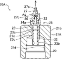
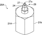
- FIGS. 1 to 4 show a depressurization plug 20A according to a modification of the first embodiment.
- the pressure relief plug 20A differs from the pressure relief plug 20 in that it has a pipe connection member 21A instead of the pipe connection member 21 of the pressure relief plug 20 described above.
- the same elements as those shown in FIGS. 1 to 4 are denoted by the same reference numerals, and detailed description thereof will be omitted.
- the pipe connection member 21A of the depressurization plug 20A has a female shape.
- the pipe connection member 21A is formed with an oil reservoir 22 in the same manner as the pipe connection member 21, but at a position closer to the hydraulic pipe than the oil reservoir 22 (lower position in FIG. 5).
- a threaded hole portion 21d having a female thread is formed, and a male coupler body of a coupler (not shown) is screwed into the threaded hole portion 21d to connect the pipe connection member 21A to the coupler.
- the entire outer peripheral surface of the pipe connection member 21A constitutes an operation surface 21b having an irregular shape, for example, a hexagon, so that it can receive the rotation operation for screwing.
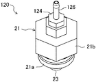
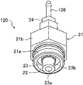
- the pressure relief plug 120 includes a poppet pressing member 128 similar to the pressure relief plug 20, but the poppet pressing member 128 includes only the pressing member main body and does not include the sealing member and the restraining member 27. It is different from the poppet pressing member 28 of the extraction plug 20 .
- the pressing member body of the poppet pressing member 128 includes a first body member 23 equivalent to the first body member 23 according to the first embodiment, and a second body member 124 .
- the second body member 124 is connected to the first body member 23 in the same manner as the second body member 24 according to the first embodiment, and is connected to the first body hole 23a of the first body member 23.
- the pipe connection member 21A is connected to the coupler 14 of the hydraulic pipe 10 shown in FIG.
- a hose connection portion 126 having a hose connection hole 126a as shown in FIGS.
- a discharge hose or the like (not shown) is connected to the hose connection portion 126, and the other end is a pail for receiving the discharged hydraulic oil. It is preferably inserted into a container such as a can.
- the hose connection hole 126a constitutes a main communication hole together with the first and second body holes 23a and 124a.
- the hose connection 126 may alternatively be piped back to the work machine tank, which eliminates the need to dump the hydraulic fluid released from the pressure relief plug 120 .
- a spherical sealing member for example, is housed in an oil reservoir 125 formed at a position (lower position) closer to the hydraulic pipe than the second body member 124 in the first body member 23, and the second body member
- the member 124 may be used not as a pressing member main body but as a restraining member that restrains the sealing member from the distal end side (upper side in FIG. 9) to the restraining position.
- the sealing member seals the outer opening of the first main body hole 23a, that is, the opening on the side opposite to the hydraulic pipe, in the restrained position, thereby preventing sudden discharge of hydraulic oil.
- Both the pressure relief plug 20A according to the modification described above and the pressure relief plug 120 according to the second embodiment are shown in FIG. 1, like the pressure relief plug 20 according to the first embodiment. To easily release the residual pressure of the hydraulic piping 10 even when the hydraulic piping 10 is twisted.
- the hydraulic piping 10 according to the first and second embodiments is incorporated in the attachment of the working machine
- the hydraulic piping to be depressurized in the present invention is not limited to this.
- the present invention can also be applied to depressurize other hydraulic lines, for example, hydraulic lines connected to hydraulic equipment other than the hydraulic equipment included in the working machine.
- the pressing member main body according to the first embodiment includes the first main body member 23 and the second main body member 24 formed with the sealing member accommodation hole 25 and connected to the first main body member 23.
- the pressing member main body may be composed of only a single member, for example, may include only the first main body member 23 without including the second main body member 24 .
- the first main body member 23 is formed with both a main communication hole and a sealing member accommodation hole located on the distal end side thereof, and the sealing member is accommodated in the sealing member accommodation hole.
- a restraining member that restrains the sealing member may be screwed directly to 23 (that is, not via the second body member 24).
- the combination of the first body member 23 having the first body hole 23a and the second body member 24 having the second body hole 24a having a diameter smaller than that of the first body hole 23a is , the outer diameter required for the sealing member 26 in order to seal the outer opening 24b of the small-diameter second main body hole 24a while suppressing flow resistance by the large-diameter first main body hole 23a. make it possible to make it smaller.
- a depressurization plug and a depressurization method using the same that can easily release the residual pressure of the hydraulic piping even when the hydraulic piping is twisted.
- the depressurization plug is connected to the coupler of the hydraulic piping having the coupler to allow the hydraulic oil inside the hydraulic piping to be discharged.
- the coupler includes a coupler body and a poppet.
- the coupler main body is formed with a hydraulic fluid flow path, which is a flow path for the hydraulic fluid.
- the poppet is arranged inside the coupler body so as to be relatively displaceable with respect to the coupler body between a closed position and an open position, which is a position inside the hydraulic pipe relative to the closed position. The poppet closes the hydraulic fluid flow path in the closed position and opens the hydraulic fluid flow path in the open position.
- the poppet is held at the closed position within the coupler body and is allowed to be displaced from the closed position to the open position by being pressed in a pressing direction toward the inside of the hydraulic pipe.
- the depressurization plug includes a pipe connection member and a poppet pressing member.
- the pipe connection member can be detachably connected to the coupler in a connection direction parallel to the pressing direction, and in a connected state connected to the coupler body, the pipe connection member can be connected in the connection direction from the coupler body. Extend.
- the poppet pressing member is held by the pipe connecting member so as to be able to press the poppet in the pressing direction in the connected state.
- the pipe connection member has both ends in the connection direction, one of which is a coupler connection end connected to the coupler main body, and the other of which is an outer end.
- a threaded hole and an oil reservoir are formed inside the pipe connecting member.
- the threaded hole extends along the connection direction from the outer end portion toward the coupler connection end portion, and has an inner peripheral surface formed with a female thread. It has a concave shape that opens toward you.
- the poppet pressing member has a shape that allows it to be inserted through the screw hole, and has an outer peripheral surface formed with a male thread that can be screwed with the female thread.
- the poppet pressing member is formed with a main communication hole and a sub-communication hole extending in the connection direction.
- the auxiliary communication hole communicates the oil reservoir with the main communication hole in a state in which the poppet pressing member presses the poppet to displace the poppet to the open position. is allowed to flow out toward the outer end portion of the pipe connection member through the secondary communication hole and the main communication hole.
- the pipe connection member is connected to the coupler of the hydraulic pipe in the connection direction, and the poppet pressing member is rotated to approach the coupler with respect to the pipe connection member.
- the poppet of the coupler can be pressed in the pressing direction inside the pipe connection member and moved from the closed position to the open position, thereby allowing the inside of the hydraulic pipe to move. can be communicated with the oil reservoir inside the pipe connection member. This allows the hydraulic fluid in the hydraulic line creating the residual pressure to flow into the oil sump, thereby allowing the residual pressure to drop.
- the hydraulic oil that has flowed into the oil reservoir portion may be discharged in the connection direction through the secondary communication hole of the poppet pressing member and the main communication hole that communicates with the secondary communication hole and extends in the connection direction. It is possible. This enables the discharge direction of the hydraulic fluid to be stably maintained in the connection direction regardless of the torsion of the hydraulic pipe, thereby allowing the discharged hydraulic fluid to be easily handled.
- the poppet pressing member preferably includes a pressing member main body, a sealing member, and a restraining member.
- the pressing member main body is formed with a main body hole extending in the connection direction and a sealing member accommodation hole communicating with the main body hole.
- the sealing member is housed in the pressing member body so as to be movable in the connection direction between a sealing position and an open position.
- the sealing member seals the outer opening of the main body hole at the sealing position, and opens the outer end away from the outer opening at the open position.
- the outer opening is the opening on the side opposite to the poppet among the openings at both ends of the main body hole.
- the restraining member is screwed to the pressing member main body so as to be relatively displaceable in the connecting direction between a restraining position and a restraining release position with respect to the pressing member main body.
- the restraining member restrains the sealing member in the sealing position from the side opposite to the body hole at the restraining position, and the sealing member moves from the sealing position to the opening position at the restraint release position.
- the restraint of the sealing member is released so as to allow this.
- the restraint member is formed with a release hole that constitutes the main communication hole together with the body hole and the sealing member accommodation hole, and the discharge hole is formed when the restraint member is at the restraint release position and the sealing member is closed. In the open position, the hydraulic fluid inside the hydraulic pipe is allowed to be discharged to the outside of the discharge side member in the connection direction through the main body hole, the sealing member accommodation hole and the discharge hole. is formed to
- the restraining member restrains the sealing member at the sealing position at the restraining position, thereby allowing the sealing member to seal the outer opening of the main body hole. This prevents hydraulic oil from spouting out immediately when the poppet pressing member moves the poppet to the open position while the pipe connection member is connected to the coupler of the hydraulic pipe. Further, in this state, the restraint member is displaced from the restraint position to the restraint release position, and the sealing member is allowed to move from the sealing position to the open position, thereby suddenly squirting hydraulic oil. to allow for gradual release through the release apertures of the restraining member rather than through the release holes.
- the sealing member has a shape that allows the peripheral edge of the outer opening to come into contact with the pressing member main body over the entire periphery of the peripheral edge at the sealing position.
- the sealing member is more preferably spherical with an outer diameter greater than the diameter of the outer end. The sealing member can reliably seal the main body hole while having a simple shape.
- the pressing member body preferably includes a first body member and a second body member.
- the first member main body includes the outer peripheral surface on which the male thread is formed, and the first member main body is formed with a first main body hole constituting the main body hole and the auxiliary communication hole.
- the second member main body can be connected to the outer end of the first member main body, and the outer end of the first member main body is connected to both ends of the first member main body in the connection direction. It is the end on the side opposite to the poppet.
- a second body hole is formed in the second member body.
- the second main body hole extends in the connecting direction and has a diameter smaller than that of the first main body hole.
- the second body hole communicates with the first body hole in the connection direction in a state where the second member body is connected to the first member body, thereby constituting the body hole together with the first body hole. do.
- the sealing member has a shape that is in contact with the second body member along the entire periphery of the periphery of the outer opening of the second body hole that constitutes the outer opening of the body hole.
- the combination of the first and second main body holes makes it possible to reduce the size of the poppet connection member while suppressing the flow path resistance of the hydraulic fluid.
- the first main body hole has a diameter larger than that of the second main body hole, thereby contributing to suppression of the flow path resistance. by having a diameter smaller than the diameter of the sealing member required to contact the second body member at the periphery of the outer opening of the second body hole to seal the outer opening. Allows for smaller diameters.
- the method includes connecting the pipe connecting member to the coupler main body of the coupler of the hydraulic pipe, and pressing the poppet pressing member against the pipe connecting member by rotating the poppet pressing member. direction to cause the poppet pressing member to press the poppet of the coupler in the pressing direction, thereby displacing the poppet from the closed position to the open position so that the inside of the hydraulic pipe moves into the oil reservoir. and discharging through the secondary communication hole and the main communication hole to the outside of the poppet pressing member in the connection direction.
Landscapes
- Engineering & Computer Science (AREA)
- General Engineering & Computer Science (AREA)
- Mechanical Engineering (AREA)
- Quick-Acting Or Multi-Walled Pipe Joints (AREA)
- Self-Closing Valves And Venting Or Aerating Valves (AREA)
Abstract
提供されるのは、油圧配管(10)のカプラ(14)に接続されて油圧配管(10)の圧抜きを可能にする圧抜きプラグ(20)である。圧抜きプラグ(20)は、カプラ(14)に対して接続方向に接続される配管接続部材(21)と、カプラ(14)のポペット(16)を押圧するポペット押圧部材(28)と、を備える。ポペット押圧部材(28)は配管接続部材(21)に対して接続方向に相対変位することによりポペット(16)を押圧することが可能である。ポペット押圧部材(28)には主連通孔(23a,24a,25,27a,27b)及び副連通孔(23b)が形成され、ポペット押圧部材(28)がポペット(16)を押圧した状態で油圧配管(10)の内部の作動油が主連通孔(23a,24a,25,27a,27b)及び副連通孔(23b)を通じて接続方向に放出されることが許容される。
Description
本発明は、油圧配管のカプラに接続されて当該油圧配管の内部の作動油を排出させる圧抜きプラグ及びこれを用いた油圧配管の圧抜き方法に関する。
従来、解体機のような組立及び分解式の作業機械において、単位配管同士を接続する継手には、クイックカプラ、セルフシールカップリング等と呼ばれる密閉式の継手が用いられる。これらの継手は、ポペット式又はスプール式のバルブを内蔵しており、着脱が容易であるのに加えて着脱時の油漏れを上記バルブが抑制するという特長を備える。
ところが、上記バルブは、継手どうしの結合のために加えられる操作力によって開弁するものであるため、単位配管同士を切り離した状態で当該単位配管内に残る圧力、すなわち残圧、が継手同士の接続に抵抗を与えて当該接続を難しくするという問題がある。この現象は、上記残圧が高い場合や上記継手が大型である場合に顕著であり、上記残圧は、例えば、閉じ込められた油(残油)の温度が外気温の上昇に伴って上昇することにより、生じ得る。
上記残圧を解消するための手段として、特許文献1は、セルフシーリングカップリングのための残圧抜取り治具を開示する。当該治具は、筒状部材と、蓋状部材と、ロッドと、排出パイプと、を備える。上記筒状部材は、上記セルフシーリングカップリングにおけるプラグ及びソケットのそれぞれに連結可能であり、かつ、当該プラグまたは当該ソケットに具備されているロック機構の一部を用いて上記筒状部材と上記プラグまたは上記ソケットとの連結状態がロックされることが可能である。上記蓋状部材は、上記筒状部材の先端に固着され、当該蓋状部材の中央部には当該筒状部材の軸芯に沿うねじ孔が形成されている。上記ロッドは、上記軸芯の方向に移動するように上記ねじ孔に螺着可能な雄ねじと、回転操作を受けることが可能な外端部と、を有する。上記残圧排出パイプは、上記筒状部材の内部と連通する。上記ロッドは、上記筒状部材が上記プラグ又は上記ソケットに連結された状態で上記蓋状部材に対して上記軸芯の方向に前進することにより、上記プラグまたは上記ソケットの内部にある弁体を押して開弁させる。これにより、上記残圧排出パイプを通じて上記油圧配管内の作動油が排出されることが可能である。
しかしながら、上記残圧抜取り治具では、上記残圧排出パイプが上記蓋状部材の径方向に延びているため、上記油圧配管のねじれなどにより上記残圧排出パイプを通じての作動油の排出方向が大きく変化する。このことは、上記残圧抜取り治具の取り扱いを難しくする。
本発明は、油圧配管のねじれなどにかかわらず油圧配管の残圧が容易に解放されることを可能にする圧抜きプラグ及びこれを用いた油圧配管の圧抜き方法を提供することを目的とする。
提供されるのは、カプラを有する油圧配管の当該カプラに接続されて該油圧配管の内部の作動油が排出されることを可能にする圧抜きプラグである。上記カプラは、カプラ本体と、ポペットと、を含む。上記カプラ本体には、上記作動油の流路である作動油流路が形成されている。上記ポペットは、上記カプラ本体に対して閉位置と上記閉位置よりも上記油圧配管の内側の位置である開位置との間で相対変位可能となるように上記カプラ本体の内部に配置される。上記ポペットは、上記閉位置では上記作動油流路を塞ぎ、上記開位置では上記作動油流路を開く。上記ポペットは、上記カプラ本体内において上記閉位置に保持されるとともに、上記油圧配管の内側に向かう押圧方向に押圧されることにより上記閉位置から上記開位置へ変位することが許容される。上記圧抜きプラグは、配管接続部材と、ポペット押圧部材と、を備える。上記配管接続部材は、上記カプラに対して上記押圧方向と平行な接続方向に脱着可能に接続されることが可能であり、上記カプラ本体に接続された接続状態で当該カプラ本体から上記接続方向に延びる。上記ポペット押圧部材は、上記接続状態で上記ポペットを上記押圧方向に押圧することが可能となるように上記配管接続部材に保持される。上記配管接続部材は、上記接続方向について両端部を有し、上記両端部の一方は上記カプラ本体に接続されるカプラ接続端部であり、上記両端部の他方は外側端部である。上記配管接続部材の内部にはねじ孔及び油溜まりが形成される。上記ねじ孔は、上記外側端部から上記カプラ接続端部に向かって上記接続方向に沿って延び、雌ねじが形成された内周面を有し、上記油溜まりは、上記接続状態において上記カプラに向かって開放されるように凹んだ形状を有する。上記ポペット押圧部材は、上記ねじ孔に挿通されることが可能な形状を有するとともに、上記雌ねじと螺合可能な雄ねじが形成された外周面を有し、上記ポペット押圧部材の回転に伴って上記配管接続部材に対して上記接続方向に相対変位させられ、これにより上記ポペットを上記押圧方向に押圧して当該ポペットを上記閉位置から上記開位置に変位させることが可能である。上記ポペット押圧部材には上記接続方向に延びる主連通孔と、副連通孔と、が形成される。上記副連通孔は、上記ポペット押圧部材が上記ポペットを押圧して上記開位置に変位させた状態において上記油溜まりと上記主連通孔とを連通し、これにより、上記油圧配管の内部の作動油が上記副連通孔及び上記主連通孔を通じて上記配管接続部材の上記外側端部に向かって流出することを許容する。
以下、本発明の実施形態を図面に基づいて説明する。
図1~図4は、本発明の第1の実施形態に係る圧抜きプラグ20を示す。当該圧抜きプラグ20は様々な機械の油圧配管に用いられる。当該機械の例として大型解体機があり、当該大型解体機は、例えば、下部走行体と、上部旋回体と、アタッチメントと、を備える。上記上部旋回体は、例えば、作動油タンク及び油圧源を含む。上記アタッチメントは、例えば、下部ブーム、ブームフットシリンダ、アーム、アームシリンダ及び破砕機を含む。このように、解体作業等を行うアタッチメントは、油圧シリンダを含む複数の油圧アクチュエータを含むため、寸法制限、重量制限などの理由で分解されて搬送される場合がある。このように分解可能に構成されたアタッチメントにはクイックカップリングを含む油圧配管が用いられ、当該油圧配管の内部には残圧が残り易い。当該残圧は、上記油圧配管を再接続する際に抵抗となって当該接続を困難にするおそれがある。
上記圧抜きプラグ20は、上記のような残圧のリリースを可能にする。具体的に、当該圧抜きプラグ20は、図1に示される油圧配管10に用いられる。上記油圧配管10は、配管本体12と、カプラ14と、を含む。上記カプラ14は、カプラ本体15とポペット16とを含み、上記圧抜きプラグ20とともに圧抜き装置を構成する。
上記カプラ本体15は、上記配管本体12の端部に装着されている。上記カプラ本体15には上記作動油の流路である作動油流路17が形成されている。この実施の形態に係る上記カプラ本体15は、本体部材15aと受入れ部材15bとを含む。上記本体部材15aは上記作動油流路17を囲む筒状をなす。上記受入れ部材15bは、上記本体部材15aの外径と略等しい内径をもつ筒状をなし、上記本体部材15aの先端側(図1では上側)の端部に外嵌された状態で当該端部に連結され、これにより、上記本体部材15aの先端側に位置する受入れ空間を画定し、上記受入れ空間は上記圧抜きプラグ20の嵌入を受け入れる。
上記ポペット16は、上記カプラ本体15に対して開位置と図1に示される閉位置との間で上記押圧方向と平行な開閉方向に相対変位可能となるように、上記カプラ本体15の内部に配置される。上記ポペット16は、図1に示される上記閉位置では上記作動油流路17を塞ぐ。上記開位置は上記閉位置よりも上記油圧配管10の内側(図1では下側)の位置であり、上記ポペット16は上記開位置で上記作動油流路17を開いて作動油の流通を許容する。
上記カプラ本体15は、複数のポペット保持部15cをさらに含む。上記複数のポペット保持部15cは上記本体部材15aの内周面から内向きに突出する。上記ポペット16は、上記複数のポペット保持部15cの先端部によって囲まれた空間に対して軸方向(図1では上下方向)に嵌入されることにより、上記カプラ本体15に対して上記軸方向に沿って上記閉位置と上記開位置との間で移動可能となるように当該複数のポペット保持部15cによって保持される。
上記カプラ14は、図示されないコイルばねをさらに含む。上記コイルばねは、上記ポペット16と上記複数のポペット保持部15cとの間に圧縮状態で介在するように配置され、これにより、上記ポペット16を上記開位置から上記閉位置に向けて(つまり先端側に)付勢する。当該付勢により、上記ポペット16は、上記弁体部16aと上記弁座部15sとが当接する上記閉位置に保持されるとともに、上記油圧配管10の内側に向かう押圧方向(図1では下方向)に押圧されることにより上記ばねの弾性変形を伴いながら上記閉位置から上記開位置へ変位することが許容される。
上記圧抜きプラグ20は、上記カプラ14とともに圧抜き装置を構成する。具体的に、上記圧抜きプラグ20は、上記カプラ本体15に接続されることにより、上記油圧配管10の内部の作動油が容易に排出されることを可能にする。具体的に、上記圧抜きプラグ20は、配管接続部材21と、ポペット押圧部材28と、を備える。
上記配管接続部材21は、上記油圧配管10の上記カプラ本体15に脱着可能に接続方向に接続される。このように上記カプラ本体15に上記配管接続部材21が接続された接続状態で上記配管接続部材21は上記カプラ本体15から上記接続方向に延びる。上記接続方向は上記押圧方向と平行な方向、この実施の形態では上記軸方向であって図1では上下方向、である。
本実施形態に係る上記配管接続部材21は、上記カプラ本体15の上記受入れ空間に嵌入されることが可能な雄型となっている。具体的に、上記配管接続部材21は、上記受入れ部材15bの上記内周面15dと嵌合することが可能な嵌合外周面21aを有する。好ましくは、上記内周面15dに雌ねじが刻まれ、上記外周面21aに上記雌ねじと螺合可能な雄ねじが刻まれる。この場合、上記配管接続部材21において上記外周面21aよりも先端側(図1では上側)の外周面は回転操作を受けることが可能な被操作面21bを構成し、当該被操作面21bは、図示されない治具によって回転操作されることが可能な形状、例えば六角形といった円以外の形状、を有する。上記カプラ14がいわゆるクイックカプラである場合、上記外周面21aには当該クイックカプラに適合した形状が与えられる。
上記配管接続部材21には油溜まり22が形成されている。上記油溜まり22は、詳しくは上記配管接続部材21のカプラ接続端部の内部に形成されて上記カプラ14に向かって開口するように凹んでいる。上記カプラ接続端部は、上記配管接続部材21の上記接続方向についての両端部のうちの一方の端部(図1では下側端部)であり、他方の端部(上側端部)は外側端部である。
上記配管接続部材21には、さらに、ねじ孔21cが形成されている。上記ねじ孔21cは、上記外側端部から上記カプラ本体15に向かって上記接続方向に沿って延び、この実施形態では上記油溜まり22に連続するように上記配管接続部材21の中心軸に沿って延びる。上記ねじ孔21cを囲む上記配管接続部材21の内周面には雌ねじが形成されている。
上記ポペット押圧部材28は、上記配管接続部材21に対して上記接続方向に相対変位可能となるように当該配管接続部材21に保持され、上記配管接続部材21が上記カプラ14に接続された接続状態において上記配管接続部材21に対して上記押圧方向に相対変位することにより、上記ポペット16を図1に示されるように上記押圧方向に押圧して閉位置まで変位させることが可能である。
上記ポペット押圧部材28は、押圧部材本体と、封止部材26と、拘束部材27と、を含み、上記押圧部材本体は、第1本体部材23と第2本体部材24とを含む。
上記第1本体部材23は、上記配管接続部材21の上記ねじ孔21cに螺合しながら挿入されることが可能な形状を有する。具体的に、上記第1本体部材23は、螺合外周面23cを有し、当該螺合外周面23cには雄ねじが形成され、当該雄ねじは上記ねじ孔21cの上記雌ねじに螺合することが可能である。上記第1本体部材23は、上記螺合外周面23cよりも先端側(図1では上側)に位置する被操作面23eをさらに含み、当該被操作面23eが回転操作されて上記第1本体部材23全体が上記配管接続部材21に対して相対回転することにより当該配管接続部材21に対して上記第1本体部材23が上記接続方向に相対変位させられることが可能である。上記第1本体部材23は、これにより、上記カプラ14の上記ポペット16を上記押圧方向に押圧して当該ポペット16を上記閉位置から図1に示される上記開位置まで変位させることが可能であり、これにより、上記油圧配管10の内部と上記油溜まり22とを連通させることが可能である。
上記第1本体部材23には、第1本体孔23aと、複数の副連通孔23bと、ねじ孔23dと、が形成されている。
上記第1本体孔23aは、上記第1本体部材23の中心軸に沿って上記接続方向に延び、上記ポペット16に向かって開口する。上記複数の副連通孔23bは、上記第1本体部材23の上記接続方向の両端部のうち上記ポペット16に近い側の端部(図1では下側端部)に形成され、上記第1本体孔23aを囲むように配置されて当該第1本体孔23aと上記油溜まり22とを径方向に連通する。上記径方向は、上記接続方向(軸方向)と直交する方向である。上記複数の副連通孔23bは、図1に示される例では一直線上に配列された一対の連通孔であるが、上記複数の副連通孔23bは互いに異なる径方向に延びる3以上の連通孔を含んでもよい。あるいは、単一の副連通孔のみが上記第1本体部材23に形成されてもよい。
上記ねじ孔23dは、上記第1本体孔23aよりも先端側に位置して当該第1本体孔23aと上記接続方向(軸方向)に連通する。上記ねじ孔23dを囲む上記第1本体部材23の内周面には雌ねじが刻まれている。
上記第2本体部材24は、上記第1本体部材23と上記接続方向(軸方向)に連結されることが可能であり、これにより上記第1本体部材23とともに上記押圧部材本体を構成する。上記第2本体部材24は、上記接続方向に並ぶ連結部24dと被操作部24eとを含む。上記連結部24dは、雄ねじが形成された外周面を有し、上記雄ねじは上記第1本体部材23の上記ねじ孔23dの上記雌ねじと螺合することが可能であり、当該螺合により上記第2本体部材24が上記第1本体部材23の先端側に位置する状態で当該第1本体部材23に脱着可能に連結される。上記被操作部24eは、上記連結部24dよりも先端側に位置する。上記被操作部24eは、上記連結部24dの外径よりも大きな外径を有し、かつ、回転操作を受けることが可能である。
上記第2本体部材24には、第2本体孔24a、封止部材収容孔25及びねじ孔24fが形成され、これらは上記第1本体孔23aに近い側(図1では下側)からこの順に上記接続方向に並んでいる。
上記第2本体孔24aは、上記第1及び第2本体部材23,24が相互連結された状態で上記第1本体孔23aと上記接続方向に連通し、これにより当該第1本体孔23aとともに本体孔(この実施形態では主連通孔の一部)を構成する。上記主連通孔は、上記ポペット押圧部材28を上記接続方向(図1では上下方向)に貫通するように当該接続方向に延びる孔である。
上記封止部材収容孔25は、上記第2本体孔24aよりも先端側に位置して上記封止部材26を収容する。上記封止部材収容孔25は、具体的には、上記封止部材26を収容することが可能な径であって上記第2本体孔24aの径よりも大きな径を有する。
上記封止部材26は、封止位置と開放位置との間で上記接続方向に移動可能となるように上記第2本体部材24の上記封止部材収容孔25内に収容される。上記封止部材26は、上記封止位置では外側開口24bを封止し、上記外側開口24bは上記本体孔(この実施形態では上記第1及び第2本体孔23a,24a)の両端開口のうち先端側(上記ポペット16と反対側;図1では上側)の開口である。具体的に、この実施形態に係る上記封止部材26は上記外側開口24bを含む上記第2本体孔24aの径よりも大きな径をもつ球状をなし、上記第2本体部材24に対して上記外側開口24bの周縁において当該周縁の全周にわたり接触することにより当該外側開口24bを封止する。上記開放位置は、上記封止位置よりも先端側の位置である。上記封止部材26は、上記開放位置では、上記外側開口24bから先端側に離れることにより上記外側開口24bを開放する。上記封止部材26の形状は、球状に限らず、上記封止位置と上記開放位置との間で移動可能であり、且つ、上記封止位置において上記外側開口24bを封止することが可能な形状であればよい。例えば、上記封止部材26は、上記外側開口24bの周縁と接触可能な半球部分と、当該半球部分よりも先端側に位置する円柱部分と、を含むものでもよい。
上記第2本体孔24aは、上記第1本体孔23aの径よりも小さい径を有することが好ましい。このことは、上記外側開口24bの径を小さくし、これにより、当該外側開口24bを封止するために必要な上記封止部材26の径を小さくすることを可能にする。また、上記第2本体部材24における上記外側開口24bの周縁は、上記封止部材26とより高い精度で密着するためにテーパ状にされていることが好ましい。
上記拘束部材27は、拘束位置と拘束解除位置との間で上記第2本体部材24に対して上記接続方向に相対変位可能となるように当該第2本体部材24に螺合される。上記拘束部材27は、上記拘束位置では、図1に示されるように上記本体孔(この実施形態では上記第1及び第2本体孔23a,24a)と反対の側(図1では上側)から上記封止部材26を上記封止位置に拘束する。上記拘束解除位置は、上記拘束位置よりも先端側(図1では上側)の位置であり、当該拘束解除位置では、上記拘束部材27は、上記封止部材26が上記封止位置から上記開放位置へ移動することを許容するように上記封止部材26の拘束を解除する。上記拘束部材27の両端部のうち上記封止部材26と接触することが可能な端部(図1では下端部)には拘束凹部27cが形成されている。当該拘束凹部27cは、当該封止部材26から離れるに従って小さくなる径をもつ円錐状をなし、当該拘束凹部27cに(この実施形態では球状の)上記封止部材26が嵌まり込むことを許容する。
上記拘束部材27は、雄ねじが形成された外周面27dを有する。これに対し、上記第2本体部材24の上記ねじ孔24fは、上記雄ねじと螺合可能な雌ねじを有し、当該ねじ孔24fに上記拘束部材27がねじ込まれている。当該螺合は、上記拘束部材27が回転操作されるのに伴って上記第2本体部材24に対して上記接続方向に変位することを生じさせ、これにより、当該拘束部材27が上記拘束位置と上記拘束解除位置との間で移動することを可能にする。
上記拘束部材27の内部には、放出孔が形成され、当該放出孔は、上記第1及び第2本体孔23a,24a及び上記封止部材収容孔25とともに上記主連通孔を構成する。この実施形態に係る上記放出孔は第1放出孔27aと第2放出孔27bとにより構成される。上記第1放出孔27aは、上記拘束部材27の先端側端部、すなわち上記拘束部材27の上記接続方向についての両端部のうち上記第1及び第2本体孔23a,24aと反対側の端部、から上記拘束凹部27cよりも手前側(先端側)の位置まで上記接続方向に延びる。上記第2放出孔27bは、上記第1放出孔27aの両端のうち上記封止部材26に近い側(図1では下側)の端とつながるように上記径方向に延び、当該第1放出孔27aと上記拘束部材27の径方向外側の空間とを上記径方向に連通する。上記第1及び第2放出孔27a,27bは、上記拘束部材27が上記拘束解除位置にあって上記封止部材26が上記開放位置に移動することを許容した状態で、上記油溜まり22から上記第1及び第2本体孔23a,24aを通じて上記封止部材収容孔25に流入した作動油がさらに上記第1及び第2放出孔27a,27bを通じて上記拘束部材27の先端側端部(図1では上端部)から接続方向に沿って上記拘束部材27の外部に放出されることを許容するように構成されている。図1に示される上記第2放出孔27bは、径方向に延びる単一の貫通孔で構成されているが、例えば互いに異なる方向に延びる複数の貫通孔で構成されてもよい。
本発明に係る主連通孔は全体として上記接続方向に延びて作動油が接続方向に放出されることを可能にする形状を有していればよく、上記第2放出孔27bのように径方向に延びる部分を部分的に含むものを除外しない。つまり、上記主連通孔は、上記油溜まり22内の作動油が上記接続方向に沿ってポペット押圧部材28の外部に放出されることを許容するように全体として当該接続方向に延びるものであればよい。
次に、本実施形態に係る上記油圧配管10の圧抜き方法について説明する。この実施形態では、上記圧抜き方法が行われる前に、作業機械の機械本体から上記油圧配管10が組み込まれたアタッチメントの取り外しが行われる。具体的には、上記アタッチメントが接続されている上記機械本体側の油圧配管回路の圧抜きが行われた後、上記の側面又は背面に配置された上記カプラ14が上記機械本体側のカプラから切り離され、これにより上記油圧配管10が上記機械本体から分離される。この分離に伴い、上記カプラ14の上記ポペット16は図示されないばねによって自動的に閉位置に移動させられ、これにより、上記油圧配管10内の作動油が漏出することを防ぐ。
次いで行われる上記圧抜き方法は、以下の配管接続工程、及び押圧工程を含む。
(1)配管接続工程
この工程では、上記のように機械本体側から分離された上記油圧配管10の上記カプラ14に、上記圧抜きプラグ20の上記配管接続部材21が接続される。この実施形態では、上記カプラ14の上記カプラ本体15を構成する上記受入れ部材15bの内周面の雌ねじと上記配管接続部材21の上記外周面21aの雄ねじとの螺合を伴いながら上記配管接続部材21が上記受入れ部材15b内にねじ込まれる。このねじ込みは、上記被操作面21bに図示されない治具が嵌合されて当該治具を用いて上記配管接続部材21が回転操作することにより行われる。
この工程では、上記のように機械本体側から分離された上記油圧配管10の上記カプラ14に、上記圧抜きプラグ20の上記配管接続部材21が接続される。この実施形態では、上記カプラ14の上記カプラ本体15を構成する上記受入れ部材15bの内周面の雌ねじと上記配管接続部材21の上記外周面21aの雄ねじとの螺合を伴いながら上記配管接続部材21が上記受入れ部材15b内にねじ込まれる。このねじ込みは、上記被操作面21bに図示されない治具が嵌合されて当該治具を用いて上記配管接続部材21が回転操作することにより行われる。
上記配管接続工程の完了後または完了前に、上記配管接続部材21への上記ポペット押圧部材28の連結が行われる。具体的には、上記配管接続部材21の上記ねじ孔21c内に上記ポペット押圧部材28(この実施形態では上記第1本体部材23)が先端側からねじ込まれる。好ましくは、上記カプラ14に上記配管接続部材21が接続された後に、上記圧抜きプラグ20の上記ポペット押圧部材28の上記第2本体部材24に上記拘束部材27がしっかりと締結されている状態であることが確認される。
上記配管接続部材21に対する上記ポペット押圧部材28の相対位置によっては、上記配管接続工程の途中で上記ポペット押圧部材28の上記第1本体部材23の端部(ポペット16に近い側の端部;図1では下端部)が上記カプラ14の上記ポペット16に接触し、この時点から上記圧抜きプラグ20が上記ポペット16から受ける反発力(上記押圧方向と反対向きの力;図1では上向きの力)が増加する。この場合でも、上記第1本体部材23の上記被操作面23e、例えば六角形の面、がレンチなどの工具で回転操作されることにより、上記カプラ14への上記配管接続部材21の締付作業は容易に行われることが可能である。
上記カプラ14に対して上記配管接続部材21が完全に締め込まれることにより、上記配管接続工程が完了する。すなわち、上記カプラ14への上記圧抜きプラグ20の取付が完了する。これにより、上記圧抜きプラグ20を使って上記油圧配管10の圧抜きを行うことが可能な状態となる。
好ましくは、上記圧抜きプラグ20の上記拘束部材27に図示しない放出用のホースが接続され、当該ホースの先端、つまり上記拘束部材27と反対側の端部、がペール缶などの容器に差し込まれる。
(2)押圧工程
上記配管接続工程の終了後、上記ポペット押圧部材28(この実施形態では上記第1本体部材23の被操作面23e)が回転操作されて当該ポペット押圧部材28が上記配管接続部材21に対して上記押圧方向に相対変位させられる。このことは、上記ポペット押圧部材28が上記カプラ14における上記図示されないばねの弾発力に抗して上記ポペット16を上記押圧方向に強制的に変位させることを生じさせ、これにより上記カプラ14内の上記作動油流路17が開通する。このようにして、押圧工程が実行される。このとき、上記油圧配管10内の作動油の一部が上記作動油流路17を通じて上記圧抜きプラグ20の上記油溜まり22に流れ込むことが許容され、これにより上記油圧配管10内の残圧が低下する。
上記配管接続工程の終了後、上記ポペット押圧部材28(この実施形態では上記第1本体部材23の被操作面23e)が回転操作されて当該ポペット押圧部材28が上記配管接続部材21に対して上記押圧方向に相対変位させられる。このことは、上記ポペット押圧部材28が上記カプラ14における上記図示されないばねの弾発力に抗して上記ポペット16を上記押圧方向に強制的に変位させることを生じさせ、これにより上記カプラ14内の上記作動油流路17が開通する。このようにして、押圧工程が実行される。このとき、上記油圧配管10内の作動油の一部が上記作動油流路17を通じて上記圧抜きプラグ20の上記油溜まり22に流れ込むことが許容され、これにより上記油圧配管10内の残圧が低下する。
本実施形態では、上記拘束部材27を上記拘束位置に位置させて上記封止部材26を上記封止位置に拘束することにより、当該封止部材26が上記第2本体孔24aの上記外側開口24bを封止する状態を保つことができる。このことは、上記押圧工程中、あるいは上記配管接続工程において上記第1本体部材23が上記ポペット16に接触した時点で、上記ポペット16が上記閉位置から上記開位置に向かって上記押圧方向に変位させられて上記作動油流路17を開通しても、その開通時点で急に作動油が噴き出して周囲を汚すことを防ぐ。
この実施形態に係る上記圧抜き方法は、さらに拘束解除工程を含む。この工程では、上記押圧工程後、上記拘束部材27が回転操作されて当該拘束部材27が緩め方向すなわち上記拘束位置から上記拘束解除位置向かう方向に変位させられることにより、上記封止部材26が上記封止位置から上記開放位置に移動することが許容されて上記外側開口24bを開放する。このことは、上記油圧配管10内の作動油が上記カプラ14、上記複数の副連通孔23b、上記本体孔(上記第1及び第2本体孔23a,24a)、上記封止部材収容孔25及び上記放出孔(上記第1及び第2放出孔27a,27b)を順に通って上記拘束部材27の外部に排出されることを許容し、これにより上記油圧配管10の内部圧力を低下させる。本実施形態では、上記油溜まり22の作動油が上記接続方向に延びる上記主連通孔(上記第1及び第2本体孔23a,24a、上記封止部材収容孔25及び上記第1及び第2放出孔27a,27bを含んで全体として上記接続方向に延びる孔)を通じて上記接続方向に放出されるので、上記油圧配管10のねじれにかかわらず上記作動油の放出方向が上記接続方向に保たれる。このことは、放出用のホース等の扱いを容易にする。
上記拘束部材27を回転操作して上記押圧部材本体(この実施形態では上記第2本体部材24)に対する上記拘束部材27の上記接続方向についての相対位置を調整することにより、上記油圧配管10の内部に残った作動油の排出量を調節して、保管時等に上記油圧配管10内で増加した(例えば外気等で上昇した)圧力を調整することができる。
上記圧抜き方法により上記油圧配管10内の残油が放出されて残圧が解放された後、上記油圧配管10の上記カプラ14から上記圧抜きプラグ20が取り外される。これに伴って上記圧抜きプラグ20による上記ポペット16の押圧が解除され、当該ポペット16は上記閉位置に復帰する。このことは、上記油圧配管10からの上記圧抜きプラグ20の取り外しに伴って上記油圧配管10内に残っている作動油が外部に吹き出すことを防ぐ。
その後、上記油圧配管10すなわち上記アタッチメント側の油圧配管と機械本体側の上記油圧配管とが上記カプラ14にて接続される。この時点で既に、上記油圧配管10内に残っていた作動油が放出されて残圧がリリースされているので、作業者は大きな抵抗を受けることなく容易に上記油圧配管どうしの接続を行うことができる。
図5、図6及び図7は、上記第1実施形態の変形例に係る圧抜きプラグ20Aを示す。当該圧抜きプラグ20Aは、上記圧抜きプラグ20における上記配管接続部材21に代えて配管接続部材21Aを具備する点で上記圧抜きプラグ20と異なる。なお、上記変形例及びその後に説明される第2実施形態では、図1~図4に示される要素と同じ要素には同じ参照符が付されてその詳細な説明は省略される。
上記圧抜きプラグ20Aの上記配管接続部材21Aは、上記配管接続部材21とは逆に雌型の形状を有する。具体的に、上記配管接続部材21Aには上記配管接続部材21と同様に油溜まり22が形成されているが、当該油溜まり22よりも油圧配管に近い位置(図5では下側の位置)に雌ねじが刻まれたねじ孔部21dが形成され、当該ねじ孔部21dに図示されないカプラの雄型のカプラ本体がねじ込まれることにより、当該カプラに上記配管接続部材21Aが接続される。また、上記配管接続部材21Aの外周面全体が異形、例えば六角形、の被操作面21bを構成し、上記ねじ込みのための回転操作を受けることが可能となっている。
図8~図11は、本発明の第2実施形態に係る圧抜きプラグ120を示す。当該圧抜きプラグ120は、上記圧抜きプラグ20と同様にポペット押圧部材128を備えるが、当該ポペット押圧部材128は押圧部材本体のみを含んで封止部材及び拘束部材27は含まない点で上記圧抜きプラグ20の上記ポペット押圧部材28と異なる。
具体的に、上記ポペット押圧部材128の上記押圧部材本体は、上記第1実施形態に係る上記第1本体部材23と同等の第1本体部材23と、第2本体部材124と、を含む。上記第2本体部材124は、上記第1実施形態に係る上記第2本体部材24と同様に上記第1本体部材23に連結され、かつ、上記第1本体部材23の第1本体孔23aと接続方向に連通する第2本体孔124aを有するが、上記第2本体部材24と異なり封止部材及び拘束部材のいずれも内蔵しない。従って、上記配管接続部材21Aが上記第1実施形態と同様に図1に示される上記油圧配管10のカプラ14に接続され、かつ、上記ポペット押圧部材28が回転操作されて上記カプラ14のポペット16を押圧方向に押圧することにより当該ポペット16による封止が解除されると、上記油圧配管10内の作動油は上記第1及び第2本体孔23a,124aを通じて直ちに放出される可能性がある。
このような状況を考慮して、本実施形態では、例えば、上記第2本体部材124に図8~図11に示されるようなホース接続孔126aを有するホース接続部126が連結され、上記ポペット押圧部材28による上記ポペット16の押圧が行われる前に、図示しない排出用ホース等の一方の端部が上記ホース接続部126に接続されて他方の端部が放出された作動油を受け入れるためのペール缶等の容器に挿入されることが、好ましい。上記ホース接続孔126aは、上記第1及び第2本体孔23a,124aとともに主連通孔を構成する。上記ホース接続部126には、あるいは、作業機械のタンクに戻る配管が接続されてもよく、このことは、上記圧抜きプラグ120から放出される作動油を捨てる必要をなくす。
あるいは、上記第1本体部材23において上記第2本体部材124よりも油圧配管に近い位置(下側の位置)に形成された油溜まり125に例えば球状の封止部材が格納され、上記第2本体部材124が押圧部材本体としてではなく上記封止部材を先端側(図9では上側)から拘束位置に拘束する拘束部材として利用されてもよい。上記封止部材は、上記拘束位置において上記第1本体孔23aの外側開口、つまり上記油圧配管と反対側の開口、を封止することにより、作動油の急な放出を防ぐことができる。
以上説明した上記変形例に係る上記圧抜きプラグ20A及び上記第2実施形態に係る上記圧抜きプラグ120のいずれも、上記第1実施形態に係る上記圧抜きプラグ20と同様、図1に示される上記油圧配管10にねじれがあるような場合でも当該油圧配管10の残圧を容易に抜くことを可能にする。
なお、以上の実施形態は、本質的に好ましい例示であって、本発明、その適用物や用途の範囲を制限することを意図するものではない。本発明は、例えば、以下のような態様も包含する。
上記第1及び第2実施形態に係る上記油圧配管10は、作業機械のアタッチメントに組み込まれているが、本発明において圧抜きの対象となる油圧配管はこれに限定されない。本発明は、その他の油圧配管、例えば、作業機械に含まれる油圧機器以外の油圧機器に接続された油圧配管の圧抜きにも適用されることが可能である。
上記第1実施形態に係る上記押圧部材本体は、上記第1本体部材23と、封止部材収容孔25が形成されて上記第1本体部材23に連結される上記第2本体部材24と、を含むが、上記押圧部材本体は、単一の部材のみにより構成されるもの、例えば上記第2本体部材24を含まずに上記第1本体部材23のみを含むもの、でもよい。例えば、上記第1本体部材23に主連通孔及びその先端側に位置する封止部材収容孔の双方が形成されて当該封止部材収容孔内に封止部材が収容され、上記第1本体部材23に直接(つまり上記第2本体部材24を介することなく)、上記封止部材を拘束する拘束部材が螺合されてもよい。ただし、上記第1本体孔23aをもつ上記第1本体部材23と、上記第1本体孔23aの径よりも小さい径を有する第2本体孔24aをもつ上記第2本体部材24と、の組み合わせは、大径の上記第1本体孔23aにより流路抵抗の抑制を図りながら小径の上記第2本体孔24aの上記外側開口24bを封止するために上記封止部材26に要求される外径を小さくすることを可能にする。
以上説明したように、油圧配管にねじれがあるような場合でも、油圧配管の残圧を容易に抜くことができる圧抜きプラグ及びこれを用いた圧抜き方法が、提供される。
上記圧抜きプラグは、カプラを有する油圧配管の当該カプラに接続されて該油圧配管の内部の作動油が排出されることを可能にする。上記カプラは、カプラ本体と、ポペットと、を含む。上記カプラ本体には、上記作動油の流路である作動油流路が形成されている。上記ポペットは、上記カプラ本体に対して閉位置と上記閉位置よりも上記油圧配管の内側の位置である開位置との間で相対変位可能となるように上記カプラ本体の内部に配置される。上記ポペットは、上記閉位置では上記作動油流路を塞ぎ、上記開位置では上記作動油流路を開く。上記ポペットは、上記カプラ本体内において上記閉位置に保持されるとともに、上記油圧配管の内側に向かう押圧方向に押圧されることにより上記閉位置から上記開位置へ変位することが許容される。上記圧抜きプラグは、配管接続部材と、ポペット押圧部材と、を備える。上記配管接続部材は、上記カプラに対して上記押圧方向と平行な接続方向に脱着可能に接続されることが可能であり、上記カプラ本体に接続された接続状態で当該カプラ本体から上記接続方向に延びる。上記ポペット押圧部材は、上記接続状態で上記ポペットを上記押圧方向に押圧することが可能となるように上記配管接続部材に保持される。上記配管接続部材は、上記接続方向について両端部を有し、上記両端部の一方は上記カプラ本体に接続されるカプラ接続端部であり、上記両端部の他方は外側端部である。上記配管接続部材の内部にはねじ孔及び油溜まりが形成される。上記ねじ孔は、上記外側端部から上記カプラ接続端部に向かって上記接続方向に沿って延び、雌ねじが形成された内周面を有し、上記油溜まりは、上記接続状態において上記カプラに向かって開放されるように凹んだ形状を有する。上記ポペット押圧部材は、上記ねじ孔に挿通されることが可能な形状を有するとともに、上記雌ねじと螺合可能な雄ねじが形成された外周面を有し、上記ポペット押圧部材の回転に伴って上記配管接続部材に対して上記接続方向に相対変位させられ、これにより上記ポペットを上記押圧方向に押圧して当該ポペットを上記閉位置から上記開位置に変位させることが可能である。上記ポペット押圧部材には上記接続方向に延びる主連通孔と、副連通孔と、が形成される。上記副連通孔は、上記ポペット押圧部材が上記ポペットを押圧して上記開位置に変位させた状態において上記油溜まりと上記主連通孔とを連通し、これにより、上記油圧配管の内部の作動油が上記副連通孔及び上記主連通孔を通じて上記配管接続部材の上記外側端部に向かって流出することを許容する。
上記圧抜きプラグによると、上記配管接続部材が上記油圧配管の上記カプラに上記接続方向に接続され、かつ、上記ポペット押圧部材が回転操作されて上記配管接続部材に対して上記カプラに近づく向きである押圧方向に相対変位することにより上記配管接続部材の内部において上記カプラのポペットを上記押圧方向に押圧して上記閉位置から上記開位置へ移動させることができ、これにより、上記油圧配管の内部と上記配管接続部材の内部の油溜まり部とを連通させることができる。このことは、残圧を生じさせている上記油圧配管内の作動油が上記油溜まり部に流れ込むことを可能にし、これにより、上記残圧が低下することを可能にする。さらに、上記油溜まり部に流入した上記作動油は、上記ポペット押圧部材の上記副連通孔及び当該副連通孔に連通して上記接続方向に延びる主連通孔を通じて上記接続方向に放出されることが可能である。このことは、上記油圧配管のねじれにかかわらず上記作動油の放出方向が安定して上記接続方向に維持されることを可能にし、これにより、放出される作動油が容易に扱われることを可能にする。
上記ポペット押圧部材は、好ましくは、押圧部材本体と、封止部材と、拘束部材と、を含む。上記押圧部材本体には上記接続方向に延びる本体孔及び当該本体孔に連通する封止部材収容孔が形成されている。上記封止部材は、封止位置と開放位置との間で上記接続方向に移動可能となるように上記押圧部材本体内に収容される。上記封止部材は、上記封止位置では上記本体孔の外側開口を封止し、上記開放位置では上記外側開口から離れて当該外側端部を開放する。上記外側開口は、上記本体孔の両端開口のうち上記ポペットと反対側の開口である。上記拘束部材は、上記押圧部材本体に対して拘束位置と拘束解除位置との間で上記接続方向に相対変位可能となるように上記押圧部材本体に螺合される。上記拘束部材は、上記拘束位置では上記本体孔と反対側から上記封止部材を上記封止位置に拘束し、上記拘束解除位置では上記封止部材が上記封止位置から上記開放位置へ移動することを許容するように上記封止部材の拘束を解除する。上記拘束部材には上記本体孔及び上記封止部材収容孔とともに上記主連通孔を構成する放出孔が形成され、上記放出孔は、上記拘束部材が上記拘束解除位置にあって上記封止部材が上記開放位置にある状態で上記油圧配管の内部の作動油が上記本体孔、上記封止部材収容孔及び上記放出孔を通って上記放出側部材の外部へ上記接続方向に放出されることを許容するように形成される。
上記拘束部材は、上記拘束位置において上記封止部材を上記封止位置に拘束することにより、上記封止部材に上記本体孔の上記外側開口を封止させることが可能である。このことは、上記油圧配管の上記カプラに上記配管接続部材が接続された状態で上記ポペット押圧部材が上記ポペットを開位置に移動させた時点で直ちに作動油が噴き出ることを抑止する。さらに、この状態で上記拘束部材が上記拘束位置から上記拘束解除位置に変位させられて上記封止部材が上記封止位置から上記開放位置へ移動することを許容することにより、作動油がいきなり噴き出すのではなく上記拘束部材の上記放出孔を通じて徐々に放出されることを可能にする。
上記封止部材は、上記封止位置において上記押圧部材本体に対して上記外側開口の周縁で当該周縁の全周にわたり接触することが可能な形状を有することが好ましい。上記封止部材は、より好ましくは、上記外側端部の径よりも大きな外径を有する球状をなす。当該封止部材は、簡単な形状を有しながら確実に上記本体孔を封止することができる。
上記押圧部材本体は、好ましくは、第1本体部材と第2本体部材とを含む。上記第1部材本体は、上記雄ねじが形成された上記外周面を含み、上記第1部材本体には上記本体孔を構成する第1本体孔と上記副連通孔とが形成されている。上記第2部材本体は、上記第1部材本体の外側端部に連結されることが可能であり、上記第1部材本体の上記外側端部は上記第1部材本体の上記接続方向の両端部のうち上記ポペットと反対側の端部である。上記第2部材本体には第2本体孔が形成されている。上記第2本体孔は、上記接続方向に延び、上記第1本体孔の径よりも小さい径を有する。上記第2本体孔は、上記第1部材本体に上記第2部材本体が連結された状態で上記第1本体孔と上記接続方向に連通し、これにより上記第1本体孔とともに上記本体孔を構成する。上記封止部材は、上記第2本体部材に対して上記本体孔の上記外側開口を構成する上記第2本体孔の外側開口の周縁において当該周縁の全周にわたり接触する形状を有する。
上記第1及び第2本体孔の組み合わせは、上記作動油の流路抵抗を抑制しながら上記ポペット接続部材の小型化を可能にする。具体的に、上記第1本体孔は、上記第2本体孔の径よりも大きな径を有することにより、上記流路抵抗の抑制に寄与する一方、上記第2本体孔は、上記第1本体孔の径よりも小さい径を有することにより、当該第2本体孔の上記外側開口の周縁において上記第2本体部材と接触して当該外側開口を封止するために必要とされる上記封止部材の径を小さくすることを可能にする。
また、上記圧抜きプラグを用いて上記油圧配管の内部の作動油を排出させるための方法が提供される。当該方法は、上記油圧配管の上記カプラの上記カプラ本体に上記配管接続部材を接続することと、上記ポペット押圧部材に回転操作を与えることにより上記配管接続部材に対して上記ポペット押圧部材を上記押圧方向に変位させて当該ポペット押圧部材に上記カプラの上記ポペットを上記押圧方向に押圧させ、これにより、上記ポペットを上記閉位置から上記開位置に変位させて上記油圧配管の内部が上記油溜まり部、上記副連通孔及び上記主連通孔を通じて上記ポペット押圧部材の外部へ上記接続方向に放出することと、を含む。
Claims (6)
- カプラを有する油圧配管の当該カプラに接続されて当該油圧配管の内部の作動油が排出されることを可能にする圧抜きプラグであって、上記カプラは、上記作動油の流路である作動油流路が形成されたカプラ本体と、上記作動油流路を塞ぐ閉位置と上記閉位置よりも上記油圧配管の内側の位置であって上記作動油流路を開く開位置との間で上記カプラ本体に対して相対変位可能となるように上記カプラ本体の内部に配置されるポペットと、を含み、上記ポペットは、上記カプラ本体内において、上記閉位置に保持されるとともに、上記油圧配管の内側に向かう押圧方向に押圧されることにより上記閉位置から上記開位置へ変位することが許容され、
上記圧抜きプラグは、
上記カプラに対して上記押圧方向と平行な接続方向に脱着可能に接続されることが可能であり、上記カプラ本体に接続された接続状態で当該カプラ本体から上記接続方向に延びる配管接続部材と、
上記接続状態で上記ポペットを上記押圧方向に押圧することが可能となるように上記配管接続部材に保持されるポペット押圧部材と、を備え、
上記配管接続部材は、上記接続方向について両端部を有し、上記両端部の一方は上記カプラ本体に接続されるカプラ接続端部であり、上記両端部の他方は外側端部であり、
上記配管接続部材の内部にはねじ孔及び油溜まりが形成され、上記ねじ孔は、上記外側端部から上記カプラ接続端部に向かって上記接続方向に沿って延び、雌ねじが形成された内周面を有し、上記油溜まりは、上記接続状態において上記カプラに向かって開放されるように凹んだ形状を有し、
上記ポペット押圧部材は、上記ねじ孔に挿通されることが可能な形状を有するとともに、上記雌ねじと螺合可能な雄ねじが形成された外周面を有し、上記ポペット押圧部材の回転に伴って上記配管接続部材に対して上記接続方向に相対変位させられ、これにより上記ポペットを上記押圧方向に押圧して当該ポペットを上記閉位置から上記開位置に変位させることが可能であり、
上記ポペット押圧部材には上記接続方向に延びる主連通孔と、副連通孔と、が形成され、上記副連通孔は、上記ポペット押圧部材が上記ポペットを押圧して上記開位置に変位させた状態において上記油溜まりと上記主連通孔とを連通し、これにより、上記油圧配管の内部の作動油が上記副連通孔及び上記主連通孔を通じて上記配管接続部材の上記外側端部に向かって流出することを許容する、圧抜きプラグ。 - 請求項1に記載の圧抜きプラグにおいて、上記ポペット押圧部材は、上記接続方向に延びる本体孔及び当該本体孔に連通する封止部材収容孔が形成された押圧部材本体と、封止位置と開放位置との間で上記接続方向に移動可能となるように上記封止部材収容孔内に収容される封止部材と、上記押圧部材本体に対して拘束位置と拘束解除位置との間で上記接続方向に相対変位可能となるように上記押圧部材本体に螺合される拘束部材と、を含み、上記封止部材は、上記封止位置では上記本体孔の外側開口を封止し、上記開放位置では上記外側開口から離れて当該外側開口を開放し、上記外側開口は上記本体孔の両端開口のうち上記ポペットと反対側の開口であり、上記拘束部材は、上記拘束位置では上記本体孔と反対側から上記封止部材を上記封止位置に拘束し、上記拘束解除位置では上記封止部材が上記封止位置から上記開放位置へ移動するのを許容するように上記封止部材の拘束を解除し、上記拘束部材には上記本体孔及び上記封止部材収容孔とともに上記主連通孔を構成する放出孔が形成され、上記放出孔は、上記拘束部材が上記拘束解除位置にあって上記封止部材が上記開放位置にある状態で上記油圧配管の内部の作動油が上記本体孔、上記封止部材収容孔及び上記放出孔を通って上記拘束部材の外部へ上記接続方向に放出されることを許容するように形成されている、圧抜きプラグ。
- 請求項2に記載の圧抜きプラグにおいて、上記封止部材は、上記封止位置において上記押圧部材本体に対し上記外側開口の周縁において当該周縁の全周にわたり接触することが可能な形状を有する、圧抜きプラグ。
- 請求項3に記載の圧抜きプラグにおいて、上記封止部材は、上記外側開口の径よりも大きな外径を有する球状をなす、圧抜きプラグ。
- 請求項3又は4に記載の圧抜きプラグにおいて、上記押圧部材本体は、第1本体部材と第2本体部材とを含み、上記第1本体部材は、上記雄ねじが形成された上記外周面を含み、上記第1本体部材には上記本体孔を構成する第1本体孔と上記副連通孔とが形成され、上記第2本体部材は、上記第1本体部材の外側端部に連結されることが可能であり、上記第1本体部材の上記外側端部は上記第1本体部材の上記接続方向の両端部のうち上記ポペットと反対側の端部であり、上記第2本体部材には、上記接続方向に延びかつ上記第1本体孔の径よりも小さい径を有する第2本体孔が形成され、上記第2本体孔は、上記第1本体部材に上記第2本体部材が連結された状態で上記第1本体孔と上記接続方向に連通し、これにより上記第1本体孔ととともに上記本体孔を構成し、上記封止部材は、上記第2本体部材における上記第2本体孔の両端開口のうち上記本体孔の外側開口を構成する開口の周縁に全周にわたり接触することが可能な形状を有する、圧抜きプラグ。
- 請求項1から5のいずれか1つに記載の圧抜きプラグを用いて油圧配管の内部の作動油を排出させるための方法であって、上記カプラは、上記作動油の流路である作動油流路が形成されたカプラ本体と、上記作動油流路を塞ぐ閉位置と上記閉位置よりも上記油圧配管の内側の位置であって上記作動油流路を開く開位置との間で上記カプラ本体に対して相対変位可能となるように上記カプラ本体の内部に配置されるポペットと、を含み、上記ポペットは、上記カプラ本体により、上記閉位置に保持されるとともに、上記油圧配管の内側に向かう押圧方向に押圧されることにより上記閉位置から上記開位置へ変位することが許容され、上記方法は、
上記油圧配管の上記カプラ本体に上記配管接続部材を上記押圧方向と平行な接続方向に接続することと、
上記ポペット押圧部材を回転させることにより上記配管接続部材に対して上記ポペット押圧部材を上記押圧方向に変位させて上記ポペット押圧部材に上記ポペットを上記押圧方向に押圧させ、これにより、上記ポペットを上記閉位置から上記開位置に変位させて上記油圧配管の内部を上記油溜まりに連通させ、上記油溜まりの作動油を上記副連通孔及び上記主連通孔を通じて上記ポペット押圧部材の外部へ上記接続方向に放出させることと、を含む油圧配管の圧抜き方法。
Applications Claiming Priority (2)
| Application Number | Priority Date | Filing Date | Title |
|---|---|---|---|
| JP2021-075304 | 2021-04-27 | ||
| JP2021075304A JP2022169332A (ja) | 2021-04-27 | 2021-04-27 | 圧抜きプラグ及び油圧配管の圧抜き方法 |
Publications (1)
| Publication Number | Publication Date |
|---|---|
| WO2022230421A1 true WO2022230421A1 (ja) | 2022-11-03 |
Family
ID=83847401
Family Applications (1)
| Application Number | Title | Priority Date | Filing Date |
|---|---|---|---|
| PCT/JP2022/012006 Ceased WO2022230421A1 (ja) | 2021-04-27 | 2022-03-16 | 圧抜きプラグ及びこれを用いた油圧配管の圧抜き方法 |
Country Status (2)
| Country | Link |
|---|---|
| JP (1) | JP2022169332A (ja) |
| WO (1) | WO2022230421A1 (ja) |
Citations (2)
| Publication number | Priority date | Publication date | Assignee | Title |
|---|---|---|---|---|
| JPS53125325U (ja) * | 1977-03-16 | 1978-10-05 | ||
| JPS6032475Y2 (ja) * | 1980-08-20 | 1985-09-27 | 株式会社竹中工務店 | セルフシ−リングカツプリングの残圧抜取り治具 |
-
2021
- 2021-04-27 JP JP2021075304A patent/JP2022169332A/ja active Pending
-
2022
- 2022-03-16 WO PCT/JP2022/012006 patent/WO2022230421A1/ja not_active Ceased
Patent Citations (2)
| Publication number | Priority date | Publication date | Assignee | Title |
|---|---|---|---|---|
| JPS53125325U (ja) * | 1977-03-16 | 1978-10-05 | ||
| JPS6032475Y2 (ja) * | 1980-08-20 | 1985-09-27 | 株式会社竹中工務店 | セルフシ−リングカツプリングの残圧抜取り治具 |
Also Published As
| Publication number | Publication date |
|---|---|
| JP2022169332A (ja) | 2022-11-09 |
Similar Documents
| Publication | Publication Date | Title |
|---|---|---|
| DK3176485T3 (en) | CLUTCH FITTING WITH SAFETY VALVE FUNCTION | |
| JP5101614B2 (ja) | 作業車に内蔵された油圧系と移動可能な油圧装置との間に設置可能な圧力開放制御手段付きの油圧接続装置 | |
| EP2378177A1 (en) | Hydraulic connection assembly with pressure discharge control | |
| CN109237179B (zh) | 安全接头 | |
| WO2007089201A1 (en) | Multiconnector for a conduit | |
| JP4454662B2 (ja) | 同軸継ぎ手 | |
| US6802492B2 (en) | Quick coupler adapter | |
| EP0380196B1 (en) | Safety connection into passages in a tubular body | |
| US20180128391A1 (en) | Nipple | |
| AU2015101965A4 (en) | Fluid supply apparatus | |
| JP2010078027A5 (ja) | ||
| JP2010078027A (ja) | 配管用継手 | |
| WO2022230421A1 (ja) | 圧抜きプラグ及びこれを用いた油圧配管の圧抜き方法 | |
| KR20110082670A (ko) | 고압 유체 이송용 커플링 | |
| WO2022124025A1 (ja) | 制流弁の開弁方法及びそれに用いられる制流弁 | |
| JP5948474B2 (ja) | 結合金具 | |
| JP2012189111A (ja) | 水道配管系の流体機器撤去方法及びそれに用いられる撤去操作治具 | |
| KR20090002170U (ko) | 유니버설 커플러의 플러그 | |
| US12510200B2 (en) | Hydraulic connection group with improved decompression system | |
| JP7573860B2 (ja) | 自動接続用継手 | |
| JP5473584B2 (ja) | 圧抜き継手 | |
| US20190054512A1 (en) | Access device for a fluid tank | |
| JP4583534B2 (ja) | 開閉機構付き管継手 | |
| CN116669897A (zh) | 用于制造非永久性液压连接的联接设备 | |
| CN121953153A (zh) | 快插接驳组件及流体输送设备 |
Legal Events
| Date | Code | Title | Description |
|---|---|---|---|
| 121 | Ep: the epo has been informed by wipo that ep was designated in this application |
Ref document number: 22795343 Country of ref document: EP Kind code of ref document: A1 |
|
| NENP | Non-entry into the national phase |
Ref country code: DE |
|
| 122 | Ep: pct application non-entry in european phase |
Ref document number: 22795343 Country of ref document: EP Kind code of ref document: A1 |