WO2022230109A1 - 遮断器 - Google Patents
遮断器 Download PDFInfo
- Publication number
- WO2022230109A1 WO2022230109A1 PCT/JP2021/016986 JP2021016986W WO2022230109A1 WO 2022230109 A1 WO2022230109 A1 WO 2022230109A1 JP 2021016986 W JP2021016986 W JP 2021016986W WO 2022230109 A1 WO2022230109 A1 WO 2022230109A1
- Authority
- WO
- WIPO (PCT)
- Prior art keywords
- thickness
- recess
- circuit breaker
- bellows member
- resin layer
- Prior art date
- Legal status (The legal status is an assumption and is not a legal conclusion. Google has not performed a legal analysis and makes no representation as to the accuracy of the status listed.)
- Ceased
Links
Images







Classifications
-
- H—ELECTRICITY
- H01—ELECTRIC ELEMENTS
- H01H—ELECTRIC SWITCHES; RELAYS; SELECTORS; EMERGENCY PROTECTIVE DEVICES
- H01H33/00—High-tension or heavy-current switches with arc-extinguishing or arc-preventing means
- H01H33/60—Switches wherein the means for extinguishing or preventing the arc do not include separate means for obtaining or increasing flow of arc-extinguishing fluid
- H01H33/66—Vacuum switches
- H01H33/662—Housings or protective screens
- H01H33/66238—Specific bellows details
-
- H—ELECTRICITY
- H01—ELECTRIC ELEMENTS
- H01H—ELECTRIC SWITCHES; RELAYS; SELECTORS; EMERGENCY PROTECTIVE DEVICES
- H01H33/00—High-tension or heavy-current switches with arc-extinguishing or arc-preventing means
- H01H33/60—Switches wherein the means for extinguishing or preventing the arc do not include separate means for obtaining or increasing flow of arc-extinguishing fluid
- H01H33/66—Vacuum switches
- H01H33/662—Housings or protective screens
- H01H33/66238—Specific bellows details
- H01H2033/66246—Details relating to the guiding of the contact rod in vacuum switch belows
Definitions
- the present disclosure relates to circuit breakers.
- a circuit breaker including a fixed electrode and a movable electrode arranged inside a container and a movable shaft for driving the movable electrode (see, for example, Japanese Utility Model Laid-Open No. 2-064132).
- a bellows member is installed so as to surround the movable shaft.
- the stretchable synthetic resin layer is formed on the inner peripheral surface of the bellows member so that the concave and convex portions of the bellows member are embedded.
- vibration of the bellows member is suppressed by consuming the impact energy applied to the bellows member due to the opening/closing operation of the movable electrode by deformation of the synthetic resin layer.
- the synthetic resin layer is formed so as to fill the irregularities of the bellows member, so the mass of the bellows member as a whole increases.
- the initial amplitude of transient vibration of the bellows member during opening and closing operations of the movable electrode increases, and as a result, the fatigue life of the bellows member may be shortened.
- the present disclosure has been made to solve the above problems, and aims to provide a circuit breaker having a bellows member with sufficient fatigue life.
- a circuit breaker includes a fixed electrode, a movable electrode, a container, a movable shaft, a bellows member, and a resin layer.
- the movable electrode is movable between a first position in contact with the fixed electrode and a second position spaced from the fixed electrode.
- the container holds the fixed electrode and the movable electrode inside.
- a movable shaft extends from the exterior to the interior of the container and is connected to the movable electrode.
- the movable shaft moves the movable electrode between the first position and the second position by moving along the extending direction of the movable shaft.
- the bellows member is arranged to surround the movable shaft.
- the bellows member includes a plurality of irregularities.
- a bellows member connects the movable shaft and the container.
- the resin layer is connected to the plurality of uneven portions of the bellows member.
- the container includes a first connection.
- a first end of the bellows member is connected to the first connecting portion.
- the movable shaft includes a second connecting portion.
- a second end located opposite to the first end of the bellows member is connected to the second connecting portion.
- the plurality of concave-convex portions includes a first concave portion, a second concave portion, and a plurality of intermediate concave portions.
- the first recess is closest to the first connecting portion.
- the second recess is closest to the second connecting portion.
- a plurality of intermediate recesses are disposed between the first recess and the second recess.
- the resin layer includes a first portion, a second portion, and a third portion.
- the first portion is connected to the first recess and has a first thickness.
- the second portion is connected to the second recess and has a second thickness.
- a third portion is connected to at least one of the plurality of intermediate recesses and has a third thickness. The third thickness is less than the first thickness and the second thickness.
- FIG. 1 is a schematic cross-sectional view of a circuit breaker according to Embodiment 1;
- FIG. FIG. 2 is a schematic partial cross-sectional view of a bellows member in the circuit breaker shown in FIG. 1;
- FIG. 2 is a schematic partial cross-sectional view of a bellows member in the circuit breaker shown in FIG. 1;
- FIG. 2 is a schematic partial cross-sectional view of a bellows member in the circuit breaker shown in FIG. 1;
- FIG. 7 is a schematic cross-sectional view of a circuit breaker according to Embodiment 2;
- 6 is a schematic partial cross-sectional view of a bellows member in the circuit breaker shown in FIG. 5;
- FIG. 6 is a schematic partial cross-sectional view of a bellows member in the circuit breaker shown in FIG. 5;
- FIG. 6 is a schematic partial cross-sectional view of a bellows member in the circuit breaker shown in FIG. 5;
- FIG. 11 is a schematic partial cross-sectional view of a bellows member in a circuit breaker according to Embodiment 3;
- FIG. 11 is a schematic partial cross-sectional view of a bellows member in a circuit breaker according to Embodiment 3;
- FIG. 11 is a schematic cross-sectional view of a circuit breaker according to Embodiment 4; 10 is a graph showing the relationship between the thickness of the resin layer of the bellows member and the recesses in the recesses and projections in the circuit breaker according to Embodiment 4.
- FIG. FIG. 11 is a schematic cross-sectional view of a bellows member in a circuit breaker according to Embodiment 5;
- FIG. 11 is a schematic cross-sectional view of a circuit breaker according to Embodiment 6;
- FIG. 11 is a schematic partial cross-sectional view of a bellows member in a circuit breaker according to Embodiment 7;
- FIG. 21 is a schematic partial cross-sectional view of a bellows member in a circuit breaker according to Embodiment 8;
- FIG. 20 is a schematic partial cross-sectional view of a bellows member in a circuit breaker according to Embodiment 9;
- FIG. 18 is a schematic diagram for explaining a method of manufacturing a bellows member in the circuit breaker shown in FIG. 17;
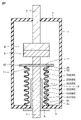
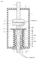
- FIG. 1 is a schematic cross-sectional view of a circuit breaker according to Embodiment 1.
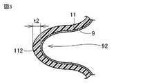
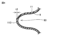
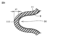
- FIG. 2 to 4 are partial cross-sectional schematic diagrams of the bellows member in the circuit breaker shown in FIG.
- the circuit breaker according to Embodiment 1 includes a fixed electrode 4, a fixed shaft 5, a movable electrode 6, a container 1, a movable shaft 7, a guide member 8, It mainly includes a bellows member 9 and a resin layer 11 .
- the movable electrode 6 is movable between a first position in contact with the fixed electrode 4 and a second position away from the fixed electrode 4 .
- the container 1 holds the fixed electrode 4 and the movable electrode 6 inside.
- the inside of the container 1 is kept in a vacuum, for example.
- the container 1 includes an upper flange 2 positioned above and a lower flange 3 positioned opposite the upper flange 2 .
- a fixed shaft 5 is fixed to the upper flange 2 .
- a fixed shaft 5 passes through the upper flange 2 and has one end located inside the container 1 .
- the fixed shaft 5 is airtightly connected to the upper flange 2 .
- a fixed electrode 4 is connected to one end of the fixed shaft 5 .
- the movable shaft 7 extends from the outside to the inside of the container 1 via the lower flange 3 .
- a through hole is formed in the lower flange 3 .
- a guide member 8 is inserted into the through hole.
- a guide member 8 is fixed to the lower flange 3 .
- the guide member 8 is a cylindrical body and has a hole.
- a flange portion projecting outward is formed at the lower portion of the guide member 8 .
- the flange portion is in contact with the surface of the lower flange 3 of the container 1 .
- a movable shaft 7 is inserted into the hole of the guide member 8 .
- the outer peripheral surface of the movable shaft 7 is in slidable contact with the inner peripheral surface of the hole of the guide member 8 .
- the movable shaft 7 is arranged to extend from the outside to the inside of the container 1 via a guide member 8 .
- the movable shaft 7 is connected outside the container 1 to a drive mechanism (not shown).
- a drive mechanism a device having any configuration can be used, and for example, a spring-type or electromagnetic drive device may be used.
- a movable electrode 6 is connected to the tip of the movable shaft 7 .
- the movable electrode 6 is arranged at a position facing the fixed electrode 4 .
- the movable electrode 6 is arranged so as to be switchable between a contact state and a separated state with respect to the fixed electrode 4 .
- the movable shaft 7 moves along the extending direction of the movable shaft 7 to move the movable electrode 6 between the first position and the second position.
- the first position of the movable electrode 6 is the position of the movable electrode 6 at which the movable electrode 6 is in contact with the fixed electrode 4 . From a different point of view, the first position is the position of the movable electrode 6 when the movable electrode 6 has moved closest to the fixed electrode 4 (closed state). At this time, the circuit breaker is in an energized state in which the fixed electrode 4 and the movable electrode 6 are electrically connected.
- the second position of the movable electrode 6 is the position of the movable electrode 6 at which the movable electrode 6 is separated from the fixed electrode 4 . From a different point of view, the second position is the position of the movable electrode 6 when the movable electrode 6 is farthest from the fixed electrode 4 (open state). At this time, in the circuit breaker, the fixed electrode 4 and the movable electrode 6 are electrically insulated from each other. Specifically, by operating the drive mechanism described above, the movable shaft 7 moves in the axial direction away from the fixed electrode 4 while the movable shaft 7 is in contact with the inner peripheral surface of the hole of the guide member 8. do.
- the movable electrode 6 is separated from the fixed electrode 4, so that the current between the fixed electrode 4 and the movable electrode 6 is interrupted.
- This operation is the opening operation of the circuit breaker.
- the opening operation of the circuit breaker moves the movable electrode 6 from the first position to the second position.
- the bellows member 9 is arranged to surround the movable shaft 7 .
- Bellows member 9 includes a plurality of uneven portions.
- convex portions (mountain portions) and concave portions (trough portions) are arranged so as to be alternately arranged.
- the bellows member 9 can expand and contract along the axial direction of the movable shaft 7 .
- the bellows member 9 contracts due to the approach of the convex portion and the concave portion of the uneven portion.
- the bellows member 9 expands due to the separation of the protrusions and recesses of the protrusions and recesses.
- the number of protrusions and recesses in the protrusions and recesses of the bellows member 9 can be any number as long as it can follow the expansion and contraction accompanying the movement of the movable shaft 7 .
- the number of protrusions may be 6 or more, and the number of recesses may be 5 or more.
- the bellows member 9 connects the movable shaft 7 and the container 1 . Specifically, the first end 9 a of the bellows member 9 is connected to the inner peripheral surface of the lower flange 3 of the container 1 . Bellows member 9 and container 1 are connected, for example, by welding or brazing. A portion of the container 1 to which the first end 9a of the bellows member 9 is connected is the first connecting portion 1a.
- An end plate 10 is connected to the movable shaft 7 .
- the end plate 10 is a flat member extending in a direction intersecting the extending direction of the movable shaft 7 .
- the end plate 10 preferably extends in a direction perpendicular to the extending direction of the movable shaft 7 .
- the shape of the end plate 10 can be any shape, it is disc-shaped, for example.
- the end plate 10 is located inside the container 1 .
- the end plate 10 is arranged so as to surround the outer peripheral surface of the movable shaft 7 .
- a second end 9 b of the bellows member 9 is connected to the end plate 10 .
- the second end 9b is the end of the bellows member 9 located opposite to the first end 9a.
- End plate 10 and bellows member 9 are connected, for example, by welding or brazing.
- a portion of the end plate 10 to which the second end 9b of the bellows member 9 is connected is a second connecting portion 10a.
- the bellows member 9 airtightly connects the inner surface of the lower flange 3 and the end plate 10 . As a result, the space outside the bellows member 9 and inside the container 1 is kept airtight.
- the plurality of uneven portions in the bellows member 9 includes a first recessed portion 91 , a second recessed portion 92 and a plurality of intermediate recessed portions 93 .
- the first recessed portion 91, the second recessed portion 92, and the intermediate recessed portion 93 are trough portions that are recessed toward the movable shaft 7 among the uneven portions.
- a convex portion is arranged between the first concave portion 91 , the second concave portion 92 and the plurality of intermediate concave portions 93 . From a different point of view, the first recess 91, the second recess 92, and the intermediate recess 93 are portions of the bellows member 9 where the diameter is relatively small.
- the plurality of protrusions on the bellows member 9 are portions where the diameter of the bellows member 9 is relatively large.
- the first recess 91 is closest to the first connecting portion 1a.
- the second recess 92 is closest to the second connecting portion 10a.
- a plurality of intermediate recesses 93 are arranged between the first recess 91 and the second recess 92 .
- the resin layer 11 is connected to the inner peripheral side of the uneven portion of the bellows member 9 .
- the resin layer 11 may be connected to the outer peripheral side of the uneven portion of the bellows member 9 .
- the resin layer 11 is connected to the entire inner peripheral surface of the uneven portion of the bellows member 9 .
- the resin layer 11 may be connected to the entire outer peripheral surface of the uneven portion of the bellows member 9 .
- any resin can be used as long as it is highly stretchable and capable of converting vibration energy into thermal energy by viscoelastic deformation.
- the resin layer 11 may contain a filler that converts vibrational energy into thermal energy by friction, such as is used in damping paint.
- Resin layer 11 includes first portion 111 , second portion 112 , and third portion 113 .
- the first portion 111 is connected to the first recess 91 .
- the first portion 111 has a first thickness t1.
- the second portion 112 is connected to the second recess 92 .
- the second portion 112 has a second thickness t2.
- the third portion 113 is connected to multiple intermediate recesses 93 .
- the third portion 113 has a third thickness t3.
- the third thickness t3 is thinner than the first thickness t1 and the second thickness t2.
- the thickness of the first portion 111 and the second portion 112 are thicker than the thickness (the third thickness t3) of the third portion 113 of the resin layer 11 located at the central portion in the extending direction.
- a lower concave portion group consisting of a first concave portion 91 and three intermediate concave portions 93
- an upper concave portion group consisting of a second concave portion 92 and three intermediate concave portions 93.
- the first thickness t1 of the first portion 111 connected to the first recessed portion 91 at the first valley from the first end 9a side is the second to fourth valleys from the first end 9a side. It is thicker than the third thickness t3 of the third portion 113 connected to the three intermediate recesses 93 .
- the second thickness t2 of the second portion 112 connected to the second recessed portion 92 at the first valley from the second end 9b side is 2 to 4 valleys from the second end 9b side. is thicker than the third thickness t3 of the third portion 113 connected to the three intermediate recesses 93 of .
- the thickness t3 of the third portion 113 connected to each of the plurality of intermediate recesses 93 may be the same or may be different.
- the first thickness t1 and the second thickness t2 may be different or the same.
- the circuit breaker shown in FIG. 1 has six intermediate recesses 93, the number of intermediate recesses 93 may be seven or more or five or less.
- the resin layer 11 is connected to all of the intermediate recesses 93 , but the third portion 113 may not be connected to any of the intermediate recesses 93 .
- resin layer 11 may include first portion 111 and second portion 112 and resin layer 11 may not be connected to intermediate recess 93 .
- the thicknesses of the first portion 111 and the second portion 112 (the first thickness t1 and the It can be said that the second thickness t2) is thicker than the third thickness of the third portion 113 .
- the third portion 113 may be connected to at least one of the multiple intermediate recesses 93 . In this case also, the thicknesses of the first portion 111 and the second portion 112 (the first thickness t1 and the thickness 2 Thickness t2) should be thick.
- the circuit breaker includes a fixed electrode 4 , a movable electrode 6 , a container 1 , a movable shaft 7 , a bellows member 9 and a resin layer 11 .
- the movable electrode 6 is movable between a first position in contact with the fixed electrode 4 and a second position away from the fixed electrode 4 .
- the container 1 holds a fixed electrode 4 and a movable electrode 6 inside.
- the movable shaft 7 extends from the outside to the inside of the container 1 and is connected to the movable electrode 6 .
- the movable shaft 7 moves along the extending direction of the movable shaft 7 to move the movable electrode 6 between the first position and the second position.
- the bellows member 9 is arranged so as to surround the movable shaft 7 .
- Bellows member 9 includes a plurality of uneven portions.
- a bellows member 9 connects the movable shaft 7 and the container 1 .
- the resin layer 11 is connected to the plurality of uneven portions of the bellows member 9 .
- the container 1 includes a first connection 1a.
- a first end 9a of a bellows member 9 is connected to the first connecting portion 1a.
- the movable shaft 7 includes a second connection portion 10a.
- a second end 9b of the bellows member 9 located opposite to the first end 9a is connected to the second connecting portion 10a.
- the plurality of concave-convex portions includes a first concave portion 91 , a second concave portion 92 and a plurality of intermediate concave portions 93 .
- the first concave portion 91 is closest to the first connecting portion 1a.
- the second recess 92 is closest to the second connecting portion 10a.
- a plurality of intermediate recesses 93 are arranged between the first recess 91 and the second recess 92 .
- Resin layer 11 includes first portion 111 , second portion 112 , and third portion 113 .
- the first portion 111 is connected to the first recess 91 and has a first thickness t1.
- the second portion 112 is connected to the second recess 92 and has a second thickness t2.
- the third portion 113 is connected to at least one of the plurality of intermediate recesses 93 and has a third thickness t3.
- the third thickness t3 is thinner than the first thickness t1 and the second thickness t
- first recess 91 and the second recess 92 which are the first recesses from the first end 9a, which is the connection portion between the bellows member 9 and the container 1, or the second end 9b, which is the connection portion between the movable shaft 7,
- the transient vibration generated in the bellows member 9 is a compressional wave of displacement transmitted in the extending direction of the bellows member 9 .
- the distortion of the bellows member 9 due to the compressional wave becomes maximum near the first end 9a and the second end 9b, which are both end portions of the bellows member 9.
- FIG. 9 Furthermore, due to the structure of the bellows member 9, the amount of strain generated in the concave portion tends to be greater than the amount of strain generated in the convex portion. Therefore, the amount of strain generated in the first concave portion 91 and the second concave portion 92, which are concave portions located first from both ends of the bellows member 9, tends to be the largest.
- the amount of deformation of the first portion 111 and the second portion 112 of the resin layer 11 connected to the first recess 91 and the second recess 92 is the largest. Since the thicknesses of the first portion 111 and the second portion 112 (the first thickness t1 and the second thickness t2) are relatively thick, the first portion 111 and the second portion 112 sufficiently absorb the vibration energy. It can be converted into heat energy. As a result, the transient vibration of the bellows member 9 can be effectively damped as described above.
- the third portion 113 may be connected to all of the multiple intermediate recesses 93 .
- the resin layer 11 is arranged over the entire bellows member 9, the transient vibration of the bellows member 9 can be damped more effectively.
- FIG. 5 is a schematic cross-sectional view of a circuit breaker according to Embodiment 2.
- FIG. 6 to 8 are partial cross-sectional schematic diagrams of the bellows member in the circuit breaker shown in FIG.
- the circuit breakers shown in FIGS. 5 to 8 basically have the same configuration as the circuit breakers shown in FIGS. 1 to 4, but the configuration of the resin layer 11 is shown in FIGS. circuit breaker.
- the thickness of the resin layer 11 connected to the first intermediate recess 931 and the second intermediate recess 932 located two valleys from the end of the bellows member 9 are thicker than the thickness of the resin layer 11 connected to the plurality of recesses (the third intermediate recesses 933) positioned after the third valley from the end of the bellows member 9.
- the plurality of intermediate recesses 93 includes a first intermediate recess 931, a second intermediate recess 932, and a plurality of third intermediate recesses 933.
- the first intermediate recess 931 is closest to the first recess 91 . That is, the first intermediate recessed portion 931 is a recessed portion of the second valley from the first end 9 a of the bellows member 9 .
- the second intermediate recess 932 is closest to the second recess 92 . That is, the second intermediate recessed portion 932 is a recessed portion of the second valley from the second end 9 b of the bellows member 9 .
- the plurality of third intermediate recesses 933 are arranged between the first intermediate recesses 931 and the second intermediate recesses 932 .
- the number of the plurality of third intermediate recesses 933 is four in FIG.
- the number of third intermediate recesses 933 may be five or more, or three or less.
- the third portion 113 of the resin layer 11 includes a first intermediate portion 1131, a second intermediate portion 1132, and a third intermediate portion 1133.
- the first intermediate portion 1131 is connected to the inner peripheral side of the first intermediate concave portion 931 .
- the first intermediate portion 1131 has a fourth thickness t4.
- the second intermediate portion 1132 is connected to the inner peripheral side of the second intermediate concave portion 932 .
- the second intermediate portion 1132 has a fifth thickness t5.
- the third intermediate portion 1133 is connected to inner peripheral sides of the plurality of third intermediate recesses 933 .
- Each of the plurality of third intermediate portions 1133 has a sixth thickness t6.
- the fourth thickness t4 and the fifth thickness t5 are thicker than the sixth thickness t6.
- the fourth thickness t4 and the fifth thickness t5 may be the same or different.
- the fourth thickness t4 may be thicker than the fifth thickness t5.
- the fifth thickness t5 may be thicker than the fourth thickness t4.
- the sixth thickness t6 of the plurality of third intermediate portions 1133 may be the same or different.
- the plurality of third intermediate recesses 933 there may be recesses in which the third intermediate portion 1133 is not formed.
- the plurality of intermediate recesses 93 may include a first intermediate recess 931 , a second intermediate recess 932 , and a plurality of third intermediate recesses 933 .
- the first intermediate recess 931 may be closest to the first recess 91 .
- the second intermediate recess 932 may be closest to the second recess 92 .
- a plurality of third intermediate recesses 933 may be arranged between the first intermediate recesses 931 and the second intermediate recesses 932 .
- Third portion 113 of resin layer 11 includes first intermediate portion 1131 , second intermediate portion 1132 , and third intermediate portion 1133 .
- the first intermediate portion 1131 may be connected to the first intermediate recess 931 and have a fourth thickness t4.
- the second intermediate portion 1132 may be connected to the second intermediate recess 932 and have a fifth thickness t5.
- the third intermediate portion 1133 may be connected to at least one of the plurality of third intermediate recesses 933 and have a sixth thickness t6.
- the fourth thickness t4 and the fifth thickness t5 may be thicker than the sixth thickness t6.
- the first intermediate recessed portion 931 and the second intermediate recessed portion 932 receive reflected waves from the first connecting portion 1a and the second connecting portion 10a as fixed ends and an input wave incident from the central portion side of the bellows member 9.
- the amount of strain generated will be equal to or greater than that of the first concave portion 91 and the second concave portion 92 .
- the thickness (fourth thickness t4 and fifth thickness t5) of the resin layer 11 at the portion where the amount of strain is likely to increase the transient vibration of the bellows member 9 can be effectively suppressed. can be effectively attenuated. As a result, the fatigue life of the bellows member 9 can be extended.
- the third intermediate portion 1133 may be connected to all of the multiple third intermediate recesses 933 . In this case, the transient vibration of the bellows member 9 can be damped more effectively.
- Embodiment 3 are partial cross-sectional schematic diagrams of the bellows member 9 in the circuit breaker according to the third embodiment.
- the circuit breaker shown in FIGS. 9 and 10 basically has the same configuration as the circuit breaker shown in FIGS. 1 to 4, but the configuration of the resin layer 11 is shown in FIGS. circuit breaker. That is, in the circuit breaker shown in FIGS. 9 and 10, the thickness of the resin layer 11 (second thickness The thickness t2) is thinner than the thickness (first thickness t1) of the resin layer 11 connected to the first concave portion 91 which is the first groove from the end of the bellows member 9 on the lower flange 3 side.
- the second thickness t2 may be thinner than the first thickness t1.
- the amount of strain generated on the side of the second recess 92 is smaller than the amount of strain generated on the side of the first recess 91 .
- the end plate 10 moves together with the movable shaft 7 during the opening operation of the circuit breaker.
- a momentary displacement load is input to the second end 9b of the bellows member 9.
- FIG. 9 As a result, in the bellows member 9, compressional waves of displacement propagate from the second end 9b side toward the first end 9a side.
- the compressional wave is reflected at the first end 9a connected to the lower flange 3 and changes its traveling direction.
- the compressional wave reflected at the first end 9a propagates from the first end 9a toward the second end 9b.
- the compressional wave passes through the first end 9a.
- the compressional wave (transient vibration) is attenuated to some extent due to the friction of the filler. Therefore, in the bellows member 9, the amount of strain on the side of the second end 9b tends to be smaller than the amount of strain on the side of the first end 9a.
- the bellows member A damping effect can be exhibited while suppressing an increase in the mass of the entire aggregate (bellows portion) of 9 and resin layer 11 . As a result, the fatigue life of the bellows member 9 can be extended.
- FIG. 11 is a schematic cross-sectional view of a circuit breaker according to Embodiment 4.
- FIG. FIG. 12 is a graph showing the relationship between the thickness of the resin layer 11 of the bellows member 9 and the concave portion of the uneven portion in the circuit breaker according to the fourth embodiment.
- the circuit breakers shown in FIGS. 11 and 12 basically have the same configuration as the circuit breakers shown in FIGS. 1 to 4, but the configuration of the resin layer 11 is shown in FIGS. circuit breaker. That is, in the circuit breaker shown in FIGS. 11 and 12, the thickness of the resin layer 11 is set to the central portion in the extension direction of the bellows member 9 from the ends (first end 9a and second end 9b) of the bellows member 9. gradually becomes thinner toward
- the plurality of intermediate recesses 93 include a first intermediate recess group 93a and a second intermediate recess group 93b.
- the first intermediate recessed portion group 93a is positioned at the end on the first recessed portion 91 side.
- the first intermediate recessed portion group 93 a consists of three intermediate recessed portions 93 arranged along the extending direction of the movable shaft 7 .
- the second intermediate recessed portion group 93b is positioned at the end on the second recessed portion 92 side.
- the second intermediate recessed portion group 93 b is composed of three intermediate recessed portions 93 arranged along the extending direction of the movable shaft 7 .
- the plurality of intermediate recesses 93 are composed only of the first intermediate recess group 93a and the second intermediate recess group 93b.
- the plurality of intermediate recesses 93 may include one or more recesses arranged between the first intermediate recess group 93a and the second intermediate recess group 93b.
- the third portion 113 of the resin layer 11 includes a first concave portion side portion 113a and a second concave portion side portion 113b.
- the first concave portion side portion 113a is connected to the inner peripheral side of the first intermediate concave portion group 93a.
- the second concave portion side portion 113b is connected to the inner peripheral side of the second intermediate concave portion group 93b.
- the thickness of the first recessed portion side portion 113a gradually decreases with distance from the first recessed portion 91, as shown in FIG.
- the vertical axis indicates the thickness of the resin layer 11 (the thickness of the first portion 111 and the first concave portion side portion 113a), and the horizontal axis indicates the number of concave portions counted from the first end 9a of the bellows member 9 ( number of valleys).
- 1 on the horizontal axis indicates the first recess 91 .
- 2 on the horizontal axis indicates the intermediate recess 93 closest to the first end 9a in the first intermediate recess group 93a.
- 3 on the horizontal axis indicates the second intermediate recess 93 from the first end 9a side in the first intermediate recess group 93a.
- 4 on the horizontal axis indicates the third intermediate recess 93 in the first intermediate recess group 93a.
- FIG. 12 shows a graph when a plurality of recesses are arranged between the first intermediate recessed portion group 93a and the second intermediate recessed portion group 93b.
- the thickness of the resin layer 11 is gradually reduced in the portions connected to the sixth recesses from the first end 9a side.
- the thickness of the portion of the resin layer 11 connected to the sixth and subsequent recesses from the first end 9a side is substantially constant as shown in FIG.
- the thickness of the second recessed portion 113b also gradually decreases with increasing distance from the second recessed portion 92, similarly to the first recessed portion 113a.
- the plurality of intermediate recesses 93 may include a first intermediate recess group 93a and a second intermediate recess group 93b.
- the first intermediate recessed portion group 93a is positioned at the end on the first recessed portion 91 side.
- the first intermediate recessed portion group 93 a may consist of three intermediate recessed portions 93 arranged along the extending direction of the movable shaft 7 .
- the second intermediate recessed portion group 93b is positioned at the end on the second recessed portion 92 side.
- the second intermediate recessed portion group 93 b may consist of three intermediate recessed portions 93 arranged along the extending direction of the movable shaft 7 .
- the third portion 113 of the resin layer 11 may include a first concave portion side portion 113a and a second concave portion side portion 113b.
- the first recessed portion side portion 113a may be connected to the first intermediate recessed portion group 93a.
- the second recessed portion side portion 113b may be connected to the second intermediate recessed portion group 93b.
- the thickness of the first recessed portion side portion 113 a may gradually decrease as the distance from the first recessed portion 91 increases.
- the thickness of the second recessed portion side portion 113b may gradually decrease as the distance from the second recessed portion 92 increases.
- the thickness of the resin layer 11 gradually decreases from the side of the first recess 91 or the side of the second recess 92 toward the central portion of the bellows member 9, the thickness of the resin layer 11 changes discontinuously. It is possible to suppress the local concentration of strain in the bellows member 9 as in the configuration. Therefore, the fatigue life of the bellows member 9 can be extended.
- Embodiment 5 is a schematic cross-sectional view of a bellows member in a circuit breaker according to Embodiment 5.
- FIG. 13 basically has the same configuration as the circuit breaker shown in FIGS. 1 to 4, but the circuit breaker shown in FIGS. is different from That is, in the circuit breaker shown in FIG. 13 , the thickness of the resin layer 11 is uniform in the circumferential direction of the bellows member 9 .
- the first recess 91 (see FIG. 1), the second recess 92 (see FIG. 1) and the intermediate recess 93 (see FIG. 1) of the bellows member 9 are Each of them is formed in an annular shape so as to surround the movable shaft 7 (see FIG. 1).
- the first portion 111 (see FIG. 2), the second portion 112 (see FIG. 3), and the third portion 113 (see FIG. 4) are each formed to extend in the circumferential direction surrounding the movable shaft 7. .
- the first thickness t1, the second thickness t2, and the third thickness t3 are uniform in the circumferential direction.
- the thickness of the resin layer 11 varies locally in the circumferential direction of the bellows member 9, the rigidity of the entire bellows portion changes in the circumferential direction.
- buckling is likely to occur in the bellows member 9 where the rigidity is low.
- pressure is applied to the bellows member 9 by evacuating the inside of the container 1 as in the circuit breaker described above, buckling is likely to occur.
- first thickness t1, second thickness t2, third thickness t3 The thicknesses of the first portion 111, the second portion 112 and the third portion 113 of the resin layer 11 connected to the bellows member 9 as described above (first thickness t1, second thickness t2, third thickness t3 ) is uniform in the circumferential direction, the occurrence of buckling as described above can be suppressed.
- the uniform thickness in the circumferential direction means that the amount of change in the thickness in the circumferential direction is 10% or less of the average value in the circumferential direction.
- Embodiment 6 is a schematic cross-sectional view of a circuit breaker according to Embodiment 6.
- FIG. FIG. 14 shows a state in which the movable electrode 6 of the circuit breaker is arranged at a second position away from the fixed electrode 4 .
- the circuit breaker shown in FIG. 14 has basically the same configuration as the circuit breaker shown in FIGS. is different from That is, in the circuit breaker shown in FIG. 14, the thickness range of the resin layer 11 is determined based on the thickness of the bellows member 9 and the pitch p of the uneven portions. Specifically, the first thickness t1 (see FIG. 2) of the first portion 111 and the second thickness t2 (see FIG.
- the first thickness t1 and the second thickness t2 are 0.25 times or less the pitch p of the plurality of uneven portions when the movable electrode 6 is arranged at the second position as shown in FIG.
- the resin layer 11 has a sufficient thickness, so that the damping effect on the bellows member 9 can be reliably obtained. can.
- the bellows member 9 is most compressed.
- Embodiment 7 is a schematic partial cross-sectional view of a bellows member in a circuit breaker according to Embodiment 7.
- FIG. FIG. 15 corresponds to FIGS. 2-4.
- FIG. 15 shows a state in which minute cracks 20 have occurred in the first portion 111 of the resin layer 11 .
- the circuit breaker shown in FIG. 15 has basically the same configuration as the circuit breaker shown in FIGS. is different from That is, in the circuit breaker shown in FIG. 15, the resin layer 11 is the self-repairing resin layer 11a containing the self-repairing material.
- the self-repairing material means a material that repairs itself when damage such as the crack 20 occurs, or that can be repaired by applying a simple treatment.
- FIG. 15 is a schematic partial cross-sectional view of a bellows member in a circuit breaker according to Embodiment 7.
- FIG. FIG. 15 corresponds to FIGS. 2-4.
- FIG. 15 shows a state in which minute cracks 20 have occurred in the first portion 111 of
- the crack 20 is filled with a repair 21 originating from the self-healing material.
- the self-healing material for example, rubber into which ionic crosslinks exhibiting reversible bonding properties have been introduced (for example, bromobutyl rubber) can be used.
- a resin layer in which fine capsules containing a self-repairing material are dispersed may be used as the self-repairing resin layer 11a.
- the self-healing material in the capsule exposed at the crack 20 reacts with an external stimulus such as air or stress at the time of crack generation, filling the crack. You may make it
- Embodiment 8 is a schematic partial cross-sectional view of a bellows member in a circuit breaker according to Embodiment 8.
- FIG. FIG. 16 corresponds to FIG.
- the circuit breaker shown in FIG. 16 basically has the same configuration as the circuit breaker shown in FIGS. 1 to 4, but the circuit breaker shown in FIGS. is different from That is, in the circuit breaker shown in FIG. 16, a luminescent resin layer 11b containing a stress-stimulated luminescent material is used as the resin layer 11.
- the stress-stimulated luminescent material means a material that can emit excitation energy as light by mechanical stimulation from the outside in a state of being excited by an electric field or the like. Mechanical stimuli include, for example, impact, compression, tension, torsion, and the like.
- the mechanoluminescent material for example, strontium aluminate whose structure is controlled by doping with eurobium can be used.
- the stress-stimulated luminescent material contained in the luminescent resin layer 11b is excited by the electric field caused by the current flowing through the circuit breaker in the closed state of the circuit breaker.
- the bellows member 9 vibrates due to the impact that accompanies the movement of the movable shaft 7 being applied to the bellows member 9 .
- Vibration energy of the bellows member 9 is converted into heat energy in the light-emitting resin layer 11 b as the resin layer 11 .
- the vibrational energy is converted into light energy by the mechanoluminescent body emitting light due to the vibration of the bellows member 9 .
- the vibrational energy generated during the opening operation of the circuit breaker can be converted not only into heat energy but also into light energy in the light emitting resin layer 11b as the resin layer 11. Therefore, the damping effect of the resin layer 11 can be increased.
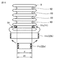
- Embodiment 9. ⁇ Configuration of circuit breaker> 17 is a schematic partial cross-sectional view of a bellows member in a circuit breaker according to Embodiment 9.
- FIG. 17 corresponds to FIG. 18A and 18B are schematic diagrams for explaining a method of manufacturing the bellows member in the circuit breaker shown in FIG. 17.
- FIG. The circuit breakers shown in FIGS. 17 and 18 basically have the same configuration as the circuit breakers shown in FIGS. 1 to 4, but the configuration of the resin layer 11 is shown in FIGS. circuit breaker. 17 and 18, the first portion 111 of the resin layer 11 is provided on the outer peripheral side of the first concave portion 91 in the bellows member 9. As shown in FIG.
- the first portion 111 is an annular elastic member 11c, as can be seen from FIG.
- the first portion 111 is in contact with the outer peripheral side of the first concave portion 91 in an elastically deformed state.
- the resin layer 11 is similarly arranged on the outer peripheral side of the second concave portion 92 (see FIG. 3) (not shown) of the bellows member 9 .
- the resin layer 11 placed on the outer peripheral side of the second recessed portion 92 may also be an elastic annular resin member, like the first portion 111 shown in FIG.
- an annular resin member 11c to be the first portion 111 of the resin layer 11 is prepared as the material 22a.
- the annular resin member 11c as the material 22a has a diameter d under no load.
- the diameter d is smaller than the outer diameter d1 of the first recess 91 of the bellows member 9 .
- the intermediate material 22b described above is arranged at a position surrounding the first concave portion 91 of the bellows member 9, and the stress applied to the intermediate material 22b is released.
- the annular resin member 11c is installed on the outer periphery of the first recess 91 in an elastically deformed state.
- the annular resin member 11c as the resin layer 11 provided on the outer periphery of the first recess 91 is elastic. It is in a deformed state (a state of being pressed by the first concave portion 91). Therefore, the resin layer 11 is reliably fixed to the outer circumference of the first recess 91 .
- the annular resin member 11c may be provided on the outer periphery of the second recessed portion 92 of the bellows member 9 as described above to form the second portion 112 (see FIG. 3). Furthermore, an annular resin member thinner than the annular resin member 11c shown in FIGS. 17 and 18 may be placed around the outer periphery of the intermediate recess 93 to serve as the third portion 113 (see FIG. 4).
- the resin layer 11 made of the annular resin member 11 c may be provided only in the first recessed portion 91 and the second recessed portion 92 . Moreover, the resin layer 11 may be provided only in either one of the first concave portion 91 and the second concave portion 92 .
- the resin layer 11 made of an annular resin member may be provided on all of the plurality of intermediate recesses 93 .
- the resin layer 11 made of an annular resin member may be provided only on the outer peripheries of some of the plurality of intermediate recesses 93 .
- At least one of the first portion 111 and the second portion 112 contacts the first concave portion 91 or the second concave portion 92 from the outer peripheral side of the bellows member 9 in an elastically deformed state.
- the first recessed portion 91 or the second recessed portion 92 of the bellows member 9 can be easily bent by deforming (enlarging the diameter of) the first portion 111 or the second portion 112 of the resin layer 11 made of, for example, an annular resin member. can be installed. As a result, it is possible to obtain the bellows member 9 and the circuit breaker with extended fatigue life at low cost without introducing special equipment for forming the above structure.
Landscapes
- Gas-Insulated Switchgears (AREA)
- Diaphragms And Bellows (AREA)
Priority Applications (4)
| Application Number | Priority Date | Filing Date | Title |
|---|---|---|---|
| DE112021007601.9T DE112021007601T5 (de) | 2021-04-28 | 2021-04-28 | Leitungsschutzschalter |
| US18/286,564 US12525416B2 (en) | 2021-04-28 | 2021-04-28 | Circuit breaker |
| PCT/JP2021/016986 WO2022230109A1 (ja) | 2021-04-28 | 2021-04-28 | 遮断器 |
| JP2023516952A JP7499956B2 (ja) | 2021-04-28 | 2021-04-28 | 遮断器 |
Applications Claiming Priority (1)
| Application Number | Priority Date | Filing Date | Title |
|---|---|---|---|
| PCT/JP2021/016986 WO2022230109A1 (ja) | 2021-04-28 | 2021-04-28 | 遮断器 |
Publications (1)
| Publication Number | Publication Date |
|---|---|
| WO2022230109A1 true WO2022230109A1 (ja) | 2022-11-03 |
Family
ID=83848094
Family Applications (1)
| Application Number | Title | Priority Date | Filing Date |
|---|---|---|---|
| PCT/JP2021/016986 Ceased WO2022230109A1 (ja) | 2021-04-28 | 2021-04-28 | 遮断器 |
Country Status (4)
| Country | Link |
|---|---|
| US (1) | US12525416B2 (https=) |
| JP (1) | JP7499956B2 (https=) |
| DE (1) | DE112021007601T5 (https=) |
| WO (1) | WO2022230109A1 (https=) |
Citations (5)
| Publication number | Priority date | Publication date | Assignee | Title |
|---|---|---|---|---|
| JPS53157864U (https=) * | 1977-05-18 | 1978-12-11 | ||
| JPH01154420A (ja) * | 1987-12-10 | 1989-06-16 | Fuji Electric Co Ltd | 真空バルブ |
| JP2003132770A (ja) * | 2001-10-23 | 2003-05-09 | Hitachi Ltd | 真空遮断器 |
| JP2013090534A (ja) * | 2011-10-21 | 2013-05-13 | Toshiba Corp | ガス絶縁機器 |
| JP2020015827A (ja) * | 2018-07-26 | 2020-01-30 | 株式会社ネオス | 硬化性樹脂組成物及び自己修復性材料 |
Family Cites Families (13)
| Publication number | Priority date | Publication date | Assignee | Title |
|---|---|---|---|---|
| US3950628A (en) * | 1974-10-10 | 1976-04-13 | Westinghouse Electric Corporation | Bellows type shorting switch |
| GB1504666A (en) * | 1975-03-22 | 1978-03-22 | Gemvac Kk | Vacuum power interrupter and method of making the same |
| US4492837A (en) * | 1983-03-21 | 1985-01-08 | General Electric Company | Guide means for the movable contact rod of a vacuum interrupter |
| JPS6065955A (ja) * | 1983-09-17 | 1985-04-15 | Mitsubishi Electric Corp | ベロ−ズ |
| JPH0264132U (https=) | 1988-11-01 | 1990-05-14 | ||
| JPH0612947A (ja) | 1992-04-17 | 1994-01-21 | Mitsubishi Electric Corp | 密封型開閉器 |
| US6043446A (en) * | 1999-06-07 | 2000-03-28 | Eaton Corporation | Vacuum switch including shield and bellows mounted on electrode support structure located in electrode circumferential groove |
| JP4765538B2 (ja) * | 2005-10-20 | 2011-09-07 | 富士電機機器制御株式会社 | 真空バルブ、真空バルブの製造方法 |
| JPWO2011117914A1 (ja) * | 2010-03-24 | 2013-07-04 | 株式会社日立製作所 | 真空バルブ及び該真空バルブを搭載したスイッチギヤ |
| DE112010005545T5 (de) | 2010-05-07 | 2013-03-07 | Mitsubishi Electric Corporation | Vakuum-Leistungsschalter |
| US8324521B2 (en) * | 2010-11-15 | 2012-12-04 | Eaton Corporation | Bellows for use in vacuum interrupters |
| JP5842385B2 (ja) * | 2011-05-18 | 2016-01-13 | 株式会社明電舎 | ベローズおよびその製造方法 |
| FR3074607A1 (fr) * | 2017-12-04 | 2019-06-07 | Schneider Electric Industries Sas | Ampoule a vide pour appareil electrique de coupure |
-
2021
- 2021-04-28 DE DE112021007601.9T patent/DE112021007601T5/de active Pending
- 2021-04-28 US US18/286,564 patent/US12525416B2/en active Active
- 2021-04-28 JP JP2023516952A patent/JP7499956B2/ja active Active
- 2021-04-28 WO PCT/JP2021/016986 patent/WO2022230109A1/ja not_active Ceased
Patent Citations (5)
| Publication number | Priority date | Publication date | Assignee | Title |
|---|---|---|---|---|
| JPS53157864U (https=) * | 1977-05-18 | 1978-12-11 | ||
| JPH01154420A (ja) * | 1987-12-10 | 1989-06-16 | Fuji Electric Co Ltd | 真空バルブ |
| JP2003132770A (ja) * | 2001-10-23 | 2003-05-09 | Hitachi Ltd | 真空遮断器 |
| JP2013090534A (ja) * | 2011-10-21 | 2013-05-13 | Toshiba Corp | ガス絶縁機器 |
| JP2020015827A (ja) * | 2018-07-26 | 2020-01-30 | 株式会社ネオス | 硬化性樹脂組成物及び自己修復性材料 |
Also Published As
| Publication number | Publication date |
|---|---|
| DE112021007601T5 (de) | 2024-02-22 |
| JPWO2022230109A1 (https=) | 2022-11-03 |
| US20240194427A1 (en) | 2024-06-13 |
| JP7499956B2 (ja) | 2024-06-14 |
| US12525416B2 (en) | 2026-01-13 |
Similar Documents
| Publication | Publication Date | Title |
|---|---|---|
| JP3954494B2 (ja) | コイン形電池 | |
| WO2014057803A1 (ja) | 複合シール | |
| CN105305881A (zh) | 基于压电效应的弧形振动能量采集器 | |
| CN106032661A (zh) | 一种刚度可变的桥墩防撞装置及方法 | |
| US20140060316A1 (en) | Vibration Energy Harvest Device | |
| US12217921B2 (en) | Vacuum circuit breaker | |
| CN109667881A (zh) | 一种防冲击摩擦隔振器 | |
| WO2022230109A1 (ja) | 遮断器 | |
| CN111853141B (zh) | 复合式声子晶体隔振器 | |
| CN102834645B (zh) | 减振装置 | |
| US20070221460A1 (en) | Vibration damping device for internal combustion engine | |
| KR20150003317A (ko) | 비균일 탄성중합체 프로파일을 구비한 비틀림 진동 댐퍼 | |
| CN106678239A (zh) | 一种橡胶与金属丝网组合的复合结构隔振器 | |
| WO2020204031A1 (ja) | 鉛プラグ入り積層ゴム支承および鉛プラグ入り積層ゴム支承の製造方法 | |
| JP2016142300A (ja) | 連結具及び遮蔽体 | |
| CN110932435A (zh) | 一种新型减震转子及电机 | |
| CN102797779A (zh) | 一种主动式金属橡胶 | |
| CN214613344U (zh) | 轨道交通用三维隔振装置 | |
| JPH03280311A (ja) | 光ファイバ複合碍子 | |
| CN109404460B (zh) | 一种磁性约束下的组合叠层摩擦阻尼吸振器 | |
| JP5662795B2 (ja) | 筒形防振装置 | |
| CN113443037B (zh) | 一种软体仿生机器人以及软体爬行器 | |
| CN115348516A (zh) | 一种微机电麦克风 | |
| CN210403295U (zh) | 一种高屏蔽性控制电缆 | |
| CN2648188Y (zh) | 金属橡胶密封环 |
Legal Events
| Date | Code | Title | Description |
|---|---|---|---|
| 121 | Ep: the epo has been informed by wipo that ep was designated in this application |
Ref document number: 21939270 Country of ref document: EP Kind code of ref document: A1 |
|
| WWE | Wipo information: entry into national phase |
Ref document number: 2023516952 Country of ref document: JP |
|
| WWE | Wipo information: entry into national phase |
Ref document number: 18286564 Country of ref document: US |
|
| WWE | Wipo information: entry into national phase |
Ref document number: 112021007601 Country of ref document: DE |
|
| 122 | Ep: pct application non-entry in european phase |
Ref document number: 21939270 Country of ref document: EP Kind code of ref document: A1 |
|
| WWG | Wipo information: grant in national office |
Ref document number: 18286564 Country of ref document: US |