WO2022224667A1 - 電力制御装置 - Google Patents
電力制御装置 Download PDFInfo
- Publication number
- WO2022224667A1 WO2022224667A1 PCT/JP2022/013056 JP2022013056W WO2022224667A1 WO 2022224667 A1 WO2022224667 A1 WO 2022224667A1 JP 2022013056 W JP2022013056 W JP 2022013056W WO 2022224667 A1 WO2022224667 A1 WO 2022224667A1
- Authority
- WO
- WIPO (PCT)
- Prior art keywords
- series
- power control
- connection portion
- control device
- unit
- Prior art date
- Legal status (The legal status is an assumption and is not a legal conclusion. Google has not performed a legal analysis and makes no representation as to the accuracy of the status listed.)
- Ceased
Links
Images


Classifications
-
- H—ELECTRICITY
- H01—ELECTRIC ELEMENTS
- H01M—PROCESSES OR MEANS, e.g. BATTERIES, FOR THE DIRECT CONVERSION OF CHEMICAL ENERGY INTO ELECTRICAL ENERGY
- H01M50/00—Constructional details or processes of manufacture of the non-active parts of electrochemical cells other than fuel cells, e.g. hybrid cells
- H01M50/20—Mountings; Secondary casings or frames; Racks, modules or packs; Suspension devices; Shock absorbers; Transport or carrying devices; Holders
- H01M50/204—Racks, modules or packs for multiple batteries or multiple cells
-
- H—ELECTRICITY
- H02—GENERATION; CONVERSION OR DISTRIBUTION OF ELECTRIC POWER
- H02J—ELECTRIC POWER NETWORKS; CIRCUIT ARRANGEMENTS OR SYSTEMS FOR SUPPLYING OR DISTRIBUTING ELECTRIC POWER; SYSTEMS FOR STORING ELECTRIC ENERGY
- H02J7/00—Circuit arrangements for charging or discharging batteries or for supplying loads from batteries
- H02J7/50—Circuit arrangements for charging or discharging batteries or for supplying loads from batteries acting upon multiple batteries simultaneously or sequentially
- H02J7/575—Parallel/serial switching of connection of batteries to charge or load circuit
-
- H—ELECTRICITY
- H01—ELECTRIC ELEMENTS
- H01M—PROCESSES OR MEANS, e.g. BATTERIES, FOR THE DIRECT CONVERSION OF CHEMICAL ENERGY INTO ELECTRICAL ENERGY
- H01M50/00—Constructional details or processes of manufacture of the non-active parts of electrochemical cells other than fuel cells, e.g. hybrid cells
- H01M50/20—Mountings; Secondary casings or frames; Racks, modules or packs; Suspension devices; Shock absorbers; Transport or carrying devices; Holders
- H01M50/269—Mechanical means for varying the arrangement of batteries or cells for different uses, e.g. for changing the number of batteries or for switching between series and parallel wiring
-
- H—ELECTRICITY
- H01—ELECTRIC ELEMENTS
- H01M—PROCESSES OR MEANS, e.g. BATTERIES, FOR THE DIRECT CONVERSION OF CHEMICAL ENERGY INTO ELECTRICAL ENERGY
- H01M50/00—Constructional details or processes of manufacture of the non-active parts of electrochemical cells other than fuel cells, e.g. hybrid cells
- H01M50/50—Current conducting connections for cells or batteries
- H01M50/502—Interconnectors for connecting terminals of adjacent batteries; Interconnectors for connecting cells outside a battery casing
- H01M50/507—Interconnectors for connecting terminals of adjacent batteries; Interconnectors for connecting cells outside a battery casing comprising an arrangement of two or more busbars within a container structure, e.g. busbar modules
-
- H—ELECTRICITY
- H02—GENERATION; CONVERSION OR DISTRIBUTION OF ELECTRIC POWER
- H02J—ELECTRIC POWER NETWORKS; CIRCUIT ARRANGEMENTS OR SYSTEMS FOR SUPPLYING OR DISTRIBUTING ELECTRIC POWER; SYSTEMS FOR STORING ELECTRIC ENERGY
- H02J7/00—Circuit arrangements for charging or discharging batteries or for supplying loads from batteries
- H02J7/70—Circuit arrangements for charging or discharging batteries or for supplying loads from batteries characterised by the mechanical construction
-
- H—ELECTRICITY
- H02—GENERATION; CONVERSION OR DISTRIBUTION OF ELECTRIC POWER
- H02J—ELECTRIC POWER NETWORKS; CIRCUIT ARRANGEMENTS OR SYSTEMS FOR SUPPLYING OR DISTRIBUTING ELECTRIC POWER; SYSTEMS FOR STORING ELECTRIC ENERGY
- H02J7/00—Circuit arrangements for charging or discharging batteries or for supplying loads from batteries
- H02J7/855—Circuit arrangements for charging or discharging batteries or for supplying loads from batteries with circuits adapted for supplying loads from the battery
-
- Y—GENERAL TAGGING OF NEW TECHNOLOGICAL DEVELOPMENTS; GENERAL TAGGING OF CROSS-SECTIONAL TECHNOLOGIES SPANNING OVER SEVERAL SECTIONS OF THE IPC; TECHNICAL SUBJECTS COVERED BY FORMER USPC CROSS-REFERENCE ART COLLECTIONS [XRACs] AND DIGESTS
- Y02—TECHNOLOGIES OR APPLICATIONS FOR MITIGATION OR ADAPTATION AGAINST CLIMATE CHANGE
- Y02E—REDUCTION OF GREENHOUSE GAS [GHG] EMISSIONS, RELATED TO ENERGY GENERATION, TRANSMISSION OR DISTRIBUTION
- Y02E60/00—Enabling technologies; Technologies with a potential or indirect contribution to GHG emissions mitigation
- Y02E60/10—Energy storage using batteries
Definitions
- the present disclosure relates to a power control device.
- the power supply device described in Japanese Patent Laying-Open No. 2007-274830 includes first and second power storage means electrically connected to an inverter, and first power storage means and second power storage means.
- first switch means arranged in a circuit for connecting the power storage means in series to the inverter; and second switch means arranged in a circuit for connecting the first power storage means and the second power storage means in parallel to the inverter. and a switch means for
- a power control device of the present disclosure is a power control device connected to a high-voltage battery configured by connecting a plurality of cell units, comprising: an electrical connection unit connecting the high-voltage battery and a load; a series-parallel switching unit that is connected to the unit and the electrical connection unit and that switches connection between the plurality of cell units between series and parallel.
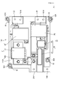
- FIG. 1 is a plan view of a power control device according to a first embodiment
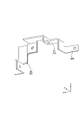
- FIG. FIG. 2 is a perspective view of a busbar with an intermediate potential connection of a third conductive path
- FIG. 3 is a perspective view of a busbar with an intermediate potential connection of a fourth conductive path
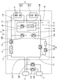
- FIG. 4 is a circuit diagram of the power controller.
- FIG. 5 is a plan view of a power control device according to a second embodiment
- FIG. 6 is a plan view of the electrical connection unit.
- FIG. 7 is a plan view of the series/parallel switching unit.
- FIG. 8 is a perspective view showing the electrical connection unit and the series/parallel switching unit exploded in the stacking direction.
- FIG. 9 is a cross-sectional view taken along line AA of FIG.
- FIG. 10 is a circuit diagram of the power control device.
- a power control device of the present disclosure is a power control device connected to a high-voltage battery configured by connecting a plurality of cell units, comprising: an electrical connection unit connecting the high-voltage battery and a load; A series-parallel switching unit connected to the plurality of cell units and the electrical connection unit and configured to switch the connection between the plurality of cell units between series and parallel is integrated.
- the power control device preferably includes a connection bus bar that connects the electrical connection unit and the series-parallel switching unit.
- the power control device may include a base member made of insulating resin, and the electrical connection unit and the series/parallel switching unit may be integrally formed on the base member.
- the electric connection unit and the series/parallel switching unit are integrally provided on the same base member, so it is easy to reduce the height of the power control device.
- the electrical connection unit and the series/parallel switching unit may be formed separately and may be stacked.
- the area occupied by the power control device that is, the area of the plane perpendicular to the axis extending in the stacking direction of the electrical connection unit and the series-parallel switching unit can be reduced.
- the electrical connection unit alone can be separated and mounted on a vehicle or the like.
- the series/parallel switching unit is laminated on the electrical connection unit, and a base member made of insulating resin constituting the series/parallel switching unit is provided with a notch, and the electrical connection unit is: a load connection portion connected to the load; a general positive electrode connection portion connected to the general positive electrode of the high voltage battery; and a general negative electrode connection portion connected to the general negative electrode of the high voltage battery; It is preferable that the total positive electrode connection portion, the total negative electrode connection portion, and the load connection portion are arranged inside the .
- the connection between the power control device and the high voltage battery and the connection between the power control device and the load can be performed.
- the electrical connection unit includes a load connection portion connected to the load, a general positive electrode connection portion connected to the general positive electrode of the high voltage battery, and a general negative electrode connection portion connected to the general negative electrode of the high voltage battery.
- the series-parallel switching unit includes a plurality of intermediate potential connection portions connected to the electrode terminals of the plurality of cell units other than the total positive electrode and the total negative electrode, and the load connection portion arranged at an end opposite to the positive electrode connection portion, the total negative electrode connection portion, and the plurality of intermediate potential connection portions, the plurality of intermediate potential connection portions being connected to the total positive electrode connection portion and the total negative electrode connection portion; , is preferably arranged between.
- Embodiment 1 of the present disclosure will be described with reference to FIGS. 1 to 4.
- FIG. 4 In the following description, except for FIG. 4, the direction indicated by arrow X is forward, the direction indicated by arrow Y is left, and the direction indicated by arrow Z is upward. Also, after the power control device 10 is described using the circuit diagram of FIG. 4, the specific configuration may be described using FIGS. 1 to 3 . As for a plurality of identical members, only some members are given reference numerals, and the reference numerals for other members may be omitted.
- the power control device 10 is arranged inside a battery pack 1 mounted on a vehicle such as an electric vehicle or a hybrid vehicle, and includes a high-voltage battery 11 and a load (not shown). to connect.
- the battery pack 1 is provided with a power control device 10, a high voltage battery 11, a power connector 12, a quick charge connector 13, and the like.
- a high-voltage battery 11 is connected to a power connector 12 via a power control device 10 .
- the power connector 12 is designed to be connected to loads such as various electronic devices.
- Quick charge connector 13 is provided by branching from a conductive path that connects power control device 10 and power connector 12 .
- Rapid charging relays 13A and 13B are provided on the conductive path connecting rapid charging connector 13 and power control device 10 .
- the quick charge relays 13A and 13B are switched to either a conductive (ON) state or an open (OFF) state by a signal from a power control unit (not shown).
- the battery pack 1 has a high-voltage battery 11 with multiple cell units 14 .
- a plurality of cell units 14 according to the present embodiment are composed of cell units 14A and cell units 14B.
- the positive electrode terminal disposed on the upper side in the drawing serves as the general positive electrode of the high-voltage battery 11 .
- the negative electrode terminal disposed on the lower side in the drawing serves as the general negative electrode of the high-voltage battery 11 .
- the total positive electrode and the total negative electrode refer to the positive and negative external connection terminals of the high-voltage battery 11 .
- Each of the cell units 14A and 14B is configured by connecting the same number of multiple storage elements 15 in series.
- a lithium ion battery for example, can be employed as the storage element 15 .
- the high-voltage battery 11 is used as a vehicle drive source and outputs high voltage.
- the voltage of the cell units 14A and 14B in this embodiment is 400 V
- the voltage of the high-voltage battery 11 is 800 V when a plurality of cell units 14 are connected in series
- the voltage of a plurality of cell units 14 is connected in parallel. It is 400V in the case of
- the power control device 10 includes an electrical connection unit 20 that connects the high-voltage battery 11 and the load, and a series-parallel switching unit 40 that switches the connection between the plurality of cell units 14 between series and parallel. And prepare.
- the electrical connection unit 20 and the series/parallel switching unit 40 are integrally formed on the same base member 10A.
- the base member 10A is a plate-like member made of insulating synthetic resin.
- the base member 10A has a bolt fastening portion to which a bolt can be fastened, and mounting grooves in which electronic components (relays, fuses, etc.) and bus bars constituting the power control device 10 are mounted.
- the electronic component and the bus bar are electrically connected by bolting and fixed to the base member 10A.
- the outline of the busbar arranged below the electronic component is indicated by a dashed line.
- the electrical connection unit 20 includes a first conductive path 21 connecting the overall positive electrode of the high voltage battery 11 and the load, and a second conductive path 22 connecting the overall negative electrode of the high voltage battery 11 and the load. , provided.
- An end portion of the first conductive path 21 connected to the general positive electrode of the high-voltage battery 11 serves as a general positive electrode connecting portion 23 .
- An end portion of the first conducting path 21 connected to the load is a load connecting portion 24A.
- An end portion of the second conductive path 22 connected to the general negative electrode of the high-voltage battery 11 serves as a general negative electrode connection portion 25 .
- the end of the second conducting path 22 connected to the load is a load connecting portion 24B.
- the first conductive path 21 is connected in series with a first system main relay 26 and a main fuse 27 .
- the main fuse 27 cuts off the overcurrent by opening the first conducting path 21 when an overcurrent flows through the first conducting path 21 .
- the first system main relay 26 is switched between ON and OFF by a signal from a power control unit (not shown).
- the first conductive path 21 is branched between the first system main relay 26 and the general positive terminal connection portion 23 and connected to a third conductive path 41 which will be described later.
- the second conductive path 22 is provided with a second system main relay 28 .
- a precharge circuit 29 is connected in parallel to the second system main relay 28 .
- the precharge circuit 29 includes a precharge relay 30 and a precharge resistor 31 connected in series.
- the second system main relay 28 and the precharge relay 30 are switched between ON and OFF by a signal from a power control unit (not shown).
- the second system main relay 28 is turned on after the precharge relay 30 is turned on, thereby suppressing the rush current from flowing through the second system main relay 28.
- the second conductive path 22 branches between the second system main relay 28 and the general negative connection portion 25 and is connected to a fourth conductive path 42 which will be described later.
- the first conductive path 21 is provided on the front side (upper side in the drawing) of the base member 10A, and includes a first system main relay 26 and a main fuse 27.
- the first system main relay 26 is arranged on the front and right side of the base member 10A
- the main fuse 27 is arranged on the front and left side of the base member 10A.
- a total positive electrode connection portion 23 arranged at the right end portion of the first conductive path 21 protrudes rightward from the right front outer edge portion of the base member 10A.
- the load connection portion 24A arranged at the left end portion of the first conductive path 21 protrudes leftward from the outer edge portion of the base member 10A near the center in the front-rear direction.
- the second conductive path 22 is provided on the rear side (lower side in the drawing) of the base member 10A, and includes a second system main relay 28 and a precharge circuit 29.
- the precharge circuit 29 includes a precharge relay 30 and a precharge resistor 31 .
- the second system main relay 28 is arranged on the rear and left side of the base member 10A, and the precharge circuit 29 is arranged on the rear and right side of the base member 10A.
- a total negative electrode connection portion 25 arranged at the right end portion of the second conductive path 22 protrudes rightward from the outer edge portion of the right rear portion of the base member 10A.
- the load connection portion 24B arranged at the left end portion of the second conductive path 22 protrudes leftward from the outer edge portion of the base member 10A near the front-rear center portion.
- the series-parallel switching unit 40 includes a third conductive path 41 connecting the first conductive path 21 and the cell unit 14B, and a fourth conductive path 41 connecting the second conductive path 22 and the cell unit 14A.
- a path 42 and a fifth conductive path 43 connecting the third conductive path 41 and the fourth conductive path 42 are provided.
- An end portion of the third conductive path 41 connected to the cell unit 14B is an intermediate potential connection portion 44B.
- An end portion of the fourth conductive path 42 connected to the cell unit 14A serves as an intermediate potential connection portion 44A.
- the intermediate potential connection portion 44B of the third conducting path 41 is connected to the positive terminal arranged on the upper side of the cell unit 14B in the drawing.
- the positive electrode terminal of the cell unit 14B is an example of electrode terminals of the plurality of cell units 14 other than the overall positive electrode and the overall negative electrode of the high-voltage battery 11 . That is, the negative terminal paired with the positive terminal of the cell unit 14B serves as the total negative electrode of the high-voltage battery 11 .
- the end of the third conductive path 41 opposite to the intermediate potential connection portion 44B is connected between the first system main relay 26 and the general positive electrode connection portion 23 of the first conductive path 21 .
- the third conductive path 41 is provided with a second relay 45B.
- the intermediate potential connection portion 44A of the fourth conductive path 42 is connected to the negative terminal arranged on the lower side of the cell unit 14A in the drawing.
- the negative terminal of the cell unit 14B is an example of electrode terminals of the plurality of cell units 14 other than the total positive electrode and the total negative electrode of the high-voltage battery 11 .
- the positive terminal paired with the negative terminal of the cell unit 14A serves as the overall positive electrode of the high-voltage battery 11 .
- the end of the fourth conducting path 42 opposite to the intermediate potential connecting part 44A is connected between the second system main relay 28 and the general negative connecting part 25 of the second conducting path 22 .
- the fourth conductive path 42 is provided with a second relay 45A.
- the fifth conducting path 43 connects the intermediate potential connecting portions 44A and 44B in series. More specifically, the fifth conductive path 43 includes a third conductive path 41 between the second relay 45B and the intermediate potential connection 44B and a fourth conductive path between the second relay 45A and the intermediate potential connection 44A. It branches from the path 42 and is provided. A first relay 46 and a first fuse 47 are provided on the fifth conducting path 43 . The first fuse 47 cuts off the overcurrent by opening the fifth conducting path 43 when an overcurrent flows through the fifth conducting path 43 .
- the first relay 46 and the second relays 45A, 45B are switched to either ON or OFF state by a signal from a power control unit (not shown). As shown in FIG. 4, when the first relay 46 is turned on and the second relays 45A and 45B are turned off, a plurality of cell units 14 can be connected in series to the electrical connection unit 20. FIG. On the other hand, when the first relay 46 is turned off and the second relays 45A and 45B are turned on, a plurality of cell units 14 can be connected in parallel to the electrical connection unit 20. FIG.
- the series-parallel connection of the plurality of cell units 14 is switched according to the voltage of the quick charger (not shown) connected to the quick charge connector 13 and the voltage required by the load connected to the power connector 12.
- the voltage of the high-voltage battery 11 can be appropriately changed.
- the voltage of each of the cell units 14A and 14B in the present embodiment is 400V
- a plurality of cell units 14 are connected in parallel and the voltage of 800V is charged.
- a plurality of cell units 14 can be connected in series.
- the series-parallel switching unit 40 (the third conductive path 41, the fourth conductive path 42, and the fifth conductive path 43) is divided into the first conductive path 21 and the second conductive path 22 in the front-rear direction. is placed between.
- the third conductive path 41 has a second relay 45B arranged behind the main fuse 27 .
- a bus bar extending rightward from the second relay 45B is a connection bus bar 48B.
- the connection bus bar 48B connects the second relay 45B and the bus bar having the overall positive connection portion 23 of the first conductive path 21 .
- the end of the third conductive path 41 opposite to the connection bus bar 48B serves as an intermediate potential connection portion 44B.
- the intermediate potential connection portion 44B protrudes rightward from the outer edge portion of the base member 10A in the vicinity of the front-rear center portion thereof.
- the third conducting path 41 between the intermediate potential connection 44B and the second relay 45B is indicated by the coarse hatching. As shown in FIG. 2, this roughly shaded portion is composed of a gate-shaped first bus bar 49 having an intermediate potential connection portion 44B and a second bus bar 50 connected to the upper left end of the first bus bar 49. It is
- the fourth conductive path 42 includes a second relay 45A arranged behind the second relay 45B.
- a bus bar extending rearward from the second relay 45A is a connection bus bar 48A.
- the connection bus bar 48A connects the second relay 45A and the bus bar having the overall negative connection portion 25 of the second conductive path 22 .
- the end of the fourth conductive path 42 opposite to the connection bus bar 48A serves as an intermediate potential connection portion 44A.
- the intermediate potential connecting portion 44A protrudes rightward from the outer edge portion of the base member 10A near the front-rear center portion.
- the fourth conductive path 42 between the second relay 45A and the intermediate potential connection portion 44A is indicated by fine hatching. As shown in FIG.
- the finely hatched portion is composed of a third bus bar 51 having an intermediate potential connection portion 44A and a fourth bus bar 52 connected to the left end of the third bus bar 51.
- the fourth busbar 52 is arranged below the second busbar 50 of the third conducting path 41 .
- the fifth conducting path 43 has a first relay 46 and a first fuse 47 arranged behind the first relay 46 .
- the first relay 46 and the first fuse 47 are surrounded by a first bus bar 49 and a second bus bar 50 indicated by coarse hatching, and a third bus bar 51 and a fourth bus bar 52 indicated by fine hatching. are distributed.
- the electrical connection unit and the series-parallel switching unit are separately arranged in the battery pack and electrically connected by a wire harness. It was necessary to connect the unit and the series-parallel switching unit.
- the electrical connection unit 20 and the series/parallel switching unit 40 are integrated and connected in advance by connection bus bars 48A and 48B. Therefore, it is possible to reduce the man-hours for connecting the power control device 10 to the high-voltage battery 11 and the load, and to downsize the power control device 10 .
- the electronic components and busbars that make up the electrical connection unit 20 and the series/parallel switching unit 40 are fixed to the same base member 10A by bolting, and the power control device 10 is integrally formed. Therefore, the vertical dimension of the power control device 10 (perpendicular to the drawing paper surface) can be particularly reduced, leading to a reduction in the height of the power control device 10 .
- a total positive electrode connection portion 23, a total negative electrode connection portion 25, and intermediate potential connection portions 44A and 44B, which are connected to the high-voltage battery 11, are arranged at the right end of the power control device 10.
- the intermediate potential connection portions 44A and 44B are arranged between the overall positive electrode connection portion 23 and the overall negative electrode connection portion 25 .
- Load connection portions 24A and 24B connected to loads are arranged at the left end portion of the power control device 10 . Therefore, it is easy to arrange the power control device 10 between the high-voltage battery 11 and the load. In addition, incorrect assembly of the power control device 10 and the high-voltage battery 11 or between the power control device 10 and the load can be suppressed.
- the second bus bar 50 of the third conductive path 41 and the fourth bus bar 52 of the fourth conductive path 42 are arranged with a vertical shift so as to intersect each other in a non-contact state. It's becoming That is, the second busbar 50 and the fourth busbar 52 cross each other.
- the third conductive path 41 and the fourth conductive path 42 are arranged in this way, as shown in FIG. It is not necessary to cross the wiring between and. Therefore, connection between the plurality of cell units 14 and the intermediate potential connection portions 44A and 44B is facilitated.
- a power control device 10 is a power control device 10 connected to a high-voltage battery 11 configured by connecting a plurality of cell units 14, and is an electrical connection unit that connects the high-voltage battery 11 and a load. 20 and a series-parallel switching unit 40 connected to the plurality of cell units 14 and the electrical connection unit 20 and switching the connection between the plurality of cell units 14 between series and parallel.
- wiring for connecting the electrical connection unit 20 and the series-parallel switching unit 40 is not required, so the man-hours for connecting the electrical connection unit 20 and the series-parallel switching unit 40 can be reduced. Further, since the electrical connection unit 20 and the series/parallel switching unit 40 are integrated, the power control device 10 can be easily miniaturized.
- the power control device 10 includes connection bus bars 48A and 48B that connect the electrical connection unit 20 and the series-parallel switching unit 40.
- the electrical connection unit 20 and the series/parallel switching unit 40 can be easily connected compared to the case where electric wires or the like are used.
- the power control device 10 includes one base member 10A made of insulating resin, and the electrical connection unit 20 and the series-parallel switching unit 40 are integrally formed on the base member 10A.
- the electrical connection unit 20 and the series/parallel switching unit 40 are integrally provided on the same base member 10A, so the power control device 10 can be easily reduced in height.
- the electrical connection unit 20 includes load connection portions 24A and 24B connected to loads, a general positive electrode connection portion 23 connected to the general positive electrode of the high voltage battery 11, and a general negative electrode of the high voltage battery 11.
- the series-parallel switching unit 40 includes a plurality of intermediate potential connection portions 44A and 44B connected to the electrode terminals of the plurality of cell units 14 other than the total positive electrode and the total negative electrode, and the load
- the connection portions 24A and 24B are arranged at the ends opposite to the overall positive electrode connection portion 23, the overall negative electrode connection portion 25, and the plurality of intermediate potential connection portions 44A and 44B. It is arranged between the total positive electrode connection portion 23 and the total negative electrode connection portion 25 .
- Embodiment 2 of the present disclosure will be described with reference to FIGS. 5 to 10.
- FIG. 10 the direction indicated by arrow X is forward, the direction indicated by arrow Y is left, and the direction indicated by arrow Z is upward.
- the specific configuration may be described using FIGS. 5 to 9 .
- the configuration of the power control device 110 according to the second embodiment is substantially the same as that of the first embodiment, except that the electrical connection unit 120 and the series-parallel switching unit 140 are provided separately. .
- members that are the same as those of the first embodiment are assigned the same reference numerals as those of the first embodiment, and descriptions of the same configurations and effects as those of the first embodiment are omitted.
- the electrical connection unit 120 and the series/parallel switching unit 140 of the present embodiment are formed separately, and the series/parallel switching unit 140 can be stacked on the electrical connection unit 120. .
- the area occupied by power control device 110 in battery pack 1 can be reduced.
- the area occupied by the power control device 110 is a plane perpendicular to the axis extending in the direction (vertical direction) in which the electrical connection unit 120 and the series/parallel switching unit 140 are stacked (plane extending in the front-rear direction and the left-right direction). is the area of
- connection bus bars 48A and 48B of the series/parallel switching unit 140 are connected to the connection portions 61A and 61B of the electrical connection unit 120, respectively.
- the connection bus bars 48A, 48B and the connection portions 61A, 61B are not connected, the series/parallel switching unit 140 and the electrical connection unit 120 are separated.
- the electrical connection unit 120 in the separated state can also be mounted alone on a vehicle or the like as a junction box, for example.
- the circuit diagram of the power control device 110 of the second embodiment is substantially the same as the circuit diagram of the power control device 10 of the first embodiment (see FIG. 4).
- Current sensors 60A, 60B, and 60C are provided in the path 21, the third conductive path 41, and the fourth conductive path 42, respectively.
- the current sensors 60A, 60B, 60C output current values in the conductive paths 21, 41, 42, and these current values are transmitted to a power control section (not shown).
- the electrical connection unit 120 and the series/parallel switching unit 140 are connected at a connection portion 61A (connection bus bar 48A) and a connection portion 61B (connection bus bar 48B).
- the electrical connection unit 120 is configured by arranging electronic components and bus bars on a base member 110A.
- a first conductive path 21 is provided extending in the left-right direction on the front side of the base member 110A.
- the first conducting path 21 includes a first system main relay 26, a main fuse 27, and a current sensor 60A.
- the right end portion of the first conductive path 21 is provided with a general positive electrode connection portion 23 and a connection portion 61B located on the rear side of the general positive electrode connection portion 23 .
- a load connecting portion 24A is provided at the left end portion of the first conducting path 21 .
- a second conductive path 22 is provided extending in the left-right direction on the rear side of the base member 110A.
- the second conductive path 22 includes a second system main relay 28 and a precharge circuit 29 (precharge relay 30 and precharge resistor 31).
- the right end portion of the second conductive path 22 is provided with a general negative electrode connection portion 25 and a connection portion 61A located behind the general negative electrode connection portion 25 .
- a load connecting portion 24B is provided at the left end portion of the first conducting path 21 .
- fixing holes 62A are vertically formed through the outer edge portions of the base member 110A at the front right, front left, rear right, and rear left. As shown in FIG. 9, the hole edge of the fixing hole 62A is provided with a projection receiving portion 63 recessed downward from the upper surface of the base member 110A.
- the series/parallel switching unit 140 is configured by arranging electronic components and bus bars on the base member 110B.
- the third conducting path 41 includes a second relay 45B and a current sensor 60B, and is arranged on the front side and right side of the base member 110B.
- a fifth bus bar 64 is connected to the second relay 45B and arranged below the second relay 45B.
- An intermediate potential connecting portion 44B is provided at the right end portion of the fifth bus bar 64 .
- a bus bar connected to the current sensor 60B and extending to the right is a connection bus bar 48B.
- the connection bus bar 48B extends greatly downward and is connected to the connection portion 61B of the electrical connection unit 120 by bolting.
- the fourth conducting path 42 includes a second relay 45A and a current sensor 60C, and is arranged on the rear side and right side of the base member 110B.
- a sixth bus bar 65 is connected to the second relay 45A and arranged below the second relay 45A.
- An intermediate potential connecting portion 44A is provided at the right end portion of the sixth bus bar 65 .
- the sixth bus bar 65 is arranged below the fifth bus bar 64, and the sixth bus bar 65 and the fifth bus bar 64 cross each other without contact. That is, the sixth busbar 65 and the fifth busbar 64 form an overpass like the second busbar 50 and the fourth busbar 52 in the first embodiment.
- the bus bar connected to the current sensor 60C and extending to the right is a connection bus bar 48A.
- the connection bus bar 48A extends largely downward and is connected to the connection portion 61A of the electrical connection unit 120 by bolting.
- the fifth conducting path 43 includes a first relay 46 and a first fuse 47, and is arranged on the left side of the base member 110B.
- fixing holes 62B are vertically formed through the outer edge portions of the base member 110B at the front right, front left, rear right, and rear left. As shown in FIG. 9, the fixing holes 62B are provided at positions corresponding to the fixing holes 62A of the base member 110A. .
- a protrusion 66 that protrudes downward from the bottom surface of the base member 110B is provided at the hole edge of the fixing hole 62B. The protrusion 66 is fitted in the protrusion receiving portion 63 so that the base members 110A and 110B can be aligned.
- bolts are inserted through the fixing holes 62A and 62B and fastened to bolt fastening portions in the battery pack 1 .
- the base member 110B has four notches 67, 68, 69, 70 that are recessed inwardly from the outer edge of the base member 110B.
- the notch portion 67 is arranged in front of the connection bus bar 48B.
- the notch 68 is arranged in front of the connection bus bar 48A.
- the notch 69 is arranged to the left of the first relay 46 .
- the notch portion 70 is arranged behind the notch portion 69 .
- inside the cutouts 67, 68, 69, 70 are the total positive electrode connection portion 23 and the total negative electrode connection portion, respectively.
- a portion 25 and load connection portions 24A and 24B are arranged. Therefore, after stacking the electrical connection unit 120 and the series/parallel switching unit 140, bolts are used to connect the overall positive electrode connection portion 23 to the overall positive electrode, the overall negative electrode connection portion 25 to the overall negative electrode, and the load connection portion. 24A, 24B and the load can be easily connected.
- the electrical connection unit 120 and the series/parallel switching unit 140 are formed separately and can be stacked.
- the area occupied by the power control device 110 that is, the area of the plane orthogonal to the axis extending in the stacking direction of the electrical connection unit 120 and the series-parallel switching unit 140 can be reduced.
- the electrical connection unit 120 alone can be separated and mounted on a vehicle or the like.
- the series/parallel switching unit 140 is stacked on the electrical connection unit 120, and the insulating resin base member 110B constituting the series/parallel switching unit 140 has notches 67, 68, 69, and 70.
- the electrical connection unit 120 includes load connection portions 24A and 24B connected to the loads, a general positive electrode connection portion 23 connected to the general positive electrode of the high voltage battery 11, and a general negative electrode of the high voltage battery 11.
- the overall positive electrode connection portion 23, the overall negative electrode connection portion 25, and the load connection portions 24A and 24B are arranged inside the cutouts 67, 68, 69, and 70, respectively.
- the connection between the power control device 110 and the high-voltage battery 11 and the connection between the power control device 110 and the load can be performed. can.
- the connections between the busbars and the connections between the electronic components and the busbars were made by bolting, but they are not limited to this and may be made by welding or the like.
- the high-voltage battery 11 is composed of two cell units 14A and 14B, but the invention is not limited to this, and the high-voltage battery may be composed of three or more cell units.
Landscapes
- Chemical & Material Sciences (AREA)
- Chemical Kinetics & Catalysis (AREA)
- Electrochemistry (AREA)
- General Chemical & Material Sciences (AREA)
- Engineering & Computer Science (AREA)
- Power Engineering (AREA)
- Charge And Discharge Circuits For Batteries Or The Like (AREA)
- Electric Propulsion And Braking For Vehicles (AREA)
Priority Applications (2)
| Application Number | Priority Date | Filing Date | Title |
|---|---|---|---|
| US18/556,431 US20240204543A1 (en) | 2021-04-21 | 2022-03-22 | Power control apparatus |
| CN202280027592.9A CN117121327A (zh) | 2021-04-21 | 2022-03-22 | 电力控制装置 |
Applications Claiming Priority (2)
| Application Number | Priority Date | Filing Date | Title |
|---|---|---|---|
| JP2021-071743 | 2021-04-21 | ||
| JP2021071743A JP7639525B2 (ja) | 2021-04-21 | 2021-04-21 | 電力制御装置 |
Publications (1)
| Publication Number | Publication Date |
|---|---|
| WO2022224667A1 true WO2022224667A1 (ja) | 2022-10-27 |
Family
ID=83722277
Family Applications (1)
| Application Number | Title | Priority Date | Filing Date |
|---|---|---|---|
| PCT/JP2022/013056 Ceased WO2022224667A1 (ja) | 2021-04-21 | 2022-03-22 | 電力制御装置 |
Country Status (4)
| Country | Link |
|---|---|
| US (1) | US20240204543A1 (https=) |
| JP (2) | JP7639525B2 (https=) |
| CN (1) | CN117121327A (https=) |
| WO (1) | WO2022224667A1 (https=) |
Cited By (2)
| Publication number | Priority date | Publication date | Assignee | Title |
|---|---|---|---|---|
| WO2024219320A1 (ja) * | 2023-04-17 | 2024-10-24 | 株式会社オートネットワーク技術研究所 | 配電装置 |
| WO2026014222A1 (ja) * | 2024-07-12 | 2026-01-15 | 株式会社デンソー | 制御システム |
Families Citing this family (1)
| Publication number | Priority date | Publication date | Assignee | Title |
|---|---|---|---|---|
| WO2024085128A1 (ja) | 2022-10-17 | 2024-04-25 | 株式会社Nttドコモ | 端末、無線通信方法及び基地局 |
Citations (5)
| Publication number | Priority date | Publication date | Assignee | Title |
|---|---|---|---|---|
| US4317162A (en) * | 1980-05-02 | 1982-02-23 | Koehler Manufacturing Co. | Battery operated luminaire with emergency switching means |
| JPH06140022A (ja) * | 1992-10-23 | 1994-05-20 | Sony Corp | 電池装置 |
| JP2013239581A (ja) * | 2012-05-15 | 2013-11-28 | Omron Corp | リレーユニットおよびその製造方法 |
| WO2016140155A1 (ja) * | 2015-03-03 | 2016-09-09 | 株式会社オートネットワーク技術研究所 | 蓄電パック |
| JP2020088087A (ja) * | 2018-11-21 | 2020-06-04 | 株式会社オートネットワーク技術研究所 | 回路構成体 |
Family Cites Families (2)
| Publication number | Priority date | Publication date | Assignee | Title |
|---|---|---|---|---|
| JP6988399B2 (ja) * | 2016-12-05 | 2022-01-05 | トヨタ自動車株式会社 | 車載用バッテリリレー接続構造 |
| JP6977581B2 (ja) * | 2018-01-22 | 2021-12-08 | トヨタ自動車株式会社 | 蓄電システム |
-
2021
- 2021-04-21 JP JP2021071743A patent/JP7639525B2/ja active Active
-
2022
- 2022-03-22 US US18/556,431 patent/US20240204543A1/en active Pending
- 2022-03-22 WO PCT/JP2022/013056 patent/WO2022224667A1/ja not_active Ceased
- 2022-03-22 CN CN202280027592.9A patent/CN117121327A/zh active Pending
-
2024
- 2024-10-30 JP JP2024190332A patent/JP7742033B2/ja active Active
Patent Citations (5)
| Publication number | Priority date | Publication date | Assignee | Title |
|---|---|---|---|---|
| US4317162A (en) * | 1980-05-02 | 1982-02-23 | Koehler Manufacturing Co. | Battery operated luminaire with emergency switching means |
| JPH06140022A (ja) * | 1992-10-23 | 1994-05-20 | Sony Corp | 電池装置 |
| JP2013239581A (ja) * | 2012-05-15 | 2013-11-28 | Omron Corp | リレーユニットおよびその製造方法 |
| WO2016140155A1 (ja) * | 2015-03-03 | 2016-09-09 | 株式会社オートネットワーク技術研究所 | 蓄電パック |
| JP2020088087A (ja) * | 2018-11-21 | 2020-06-04 | 株式会社オートネットワーク技術研究所 | 回路構成体 |
Cited By (2)
| Publication number | Priority date | Publication date | Assignee | Title |
|---|---|---|---|---|
| WO2024219320A1 (ja) * | 2023-04-17 | 2024-10-24 | 株式会社オートネットワーク技術研究所 | 配電装置 |
| WO2026014222A1 (ja) * | 2024-07-12 | 2026-01-15 | 株式会社デンソー | 制御システム |
Also Published As
| Publication number | Publication date |
|---|---|
| JP2025013380A (ja) | 2025-01-24 |
| JP2022166494A (ja) | 2022-11-02 |
| CN117121327A (zh) | 2023-11-24 |
| US20240204543A1 (en) | 2024-06-20 |
| JP7742033B2 (ja) | 2025-09-19 |
| JP7639525B2 (ja) | 2025-03-05 |
Similar Documents
| Publication | Publication Date | Title |
|---|---|---|
| JP7742033B2 (ja) | 電力制御装置 | |
| KR102033003B1 (ko) | 프레임 조립체 | |
| US11643033B2 (en) | Motor vehicle electrical system and vehicle with a motor vehicle electrical system | |
| JP5285960B2 (ja) | 組電池の電源制御装置 | |
| CN104205420B (zh) | 电池系统或储电器电池电芯的电芯连接器、电池和车辆 | |
| JP2009004323A (ja) | 電源装置 | |
| CN108231616B (zh) | 电压检测构造和电压检测模块 | |
| US12322827B2 (en) | Distribution system for unswitched high voltage power | |
| CN110337736B (zh) | 电池包、托架 | |
| KR102531176B1 (ko) | 전기자동차의 전력 분배 장치 | |
| CN110556497A (zh) | 用于机动车的高压电池和机动车 | |
| JP5430957B2 (ja) | バッテリシステム | |
| JP2005130636A (ja) | ジャンクションブロックの回路構造 | |
| JP2022166494A5 (https=) | ||
| JP7779148B2 (ja) | 蓄電設備 | |
| JP7309314B2 (ja) | 車両用電池パック | |
| CN115513610B (zh) | 电池包和包括电池包的车辆 | |
| JP2024112611A (ja) | バスバーモジュール | |
| JP7255396B2 (ja) | 電気接続箱 | |
| JP7746317B2 (ja) | 電池パック | |
| CN112498175A (zh) | 具有电蓄能器的地面搬运车 | |
| JP7610086B1 (ja) | バッテリユニット | |
| US20250273787A1 (en) | Battery pack | |
| JP2018133215A (ja) | バッテリパック | |
| JP4697100B2 (ja) | 電池モジュール |
Legal Events
| Date | Code | Title | Description |
|---|---|---|---|
| 121 | Ep: the epo has been informed by wipo that ep was designated in this application |
Ref document number: 22791446 Country of ref document: EP Kind code of ref document: A1 |
|
| WWE | Wipo information: entry into national phase |
Ref document number: 18556431 Country of ref document: US |
|
| NENP | Non-entry into the national phase |
Ref country code: DE |
|
| 122 | Ep: pct application non-entry in european phase |
Ref document number: 22791446 Country of ref document: EP Kind code of ref document: A1 |