WO2022224636A1 - Inspection device - Google Patents
Inspection device Download PDFInfo
- Publication number
- WO2022224636A1 WO2022224636A1 PCT/JP2022/011654 JP2022011654W WO2022224636A1 WO 2022224636 A1 WO2022224636 A1 WO 2022224636A1 JP 2022011654 W JP2022011654 W JP 2022011654W WO 2022224636 A1 WO2022224636 A1 WO 2022224636A1
- Authority
- WO
- WIPO (PCT)
- Prior art keywords
- unit
- imaging
- luminance
- defect
- periodic
- Prior art date
Links
- 238000007689 inspection Methods 0.000 title claims abstract description 134
- 230000000737 periodic effect Effects 0.000 claims abstract description 241
- 238000001514 detection method Methods 0.000 claims abstract description 59
- 230000008859 change Effects 0.000 claims abstract description 20
- 230000007547 defect Effects 0.000 claims description 380
- 238000003384 imaging method Methods 0.000 claims description 287
- 230000003287 optical effect Effects 0.000 claims description 123
- 238000005286 illumination Methods 0.000 claims description 98
- 238000005259 measurement Methods 0.000 claims description 93
- 238000011156 evaluation Methods 0.000 claims description 88
- 230000007246 mechanism Effects 0.000 claims description 85
- 238000004364 calculation method Methods 0.000 claims description 20
- 239000000356 contaminant Substances 0.000 claims description 16
- 238000004519 manufacturing process Methods 0.000 description 27
- 239000010408 film Substances 0.000 description 16
- 238000010586 diagram Methods 0.000 description 14
- 229920005989 resin Polymers 0.000 description 12
- 239000011347 resin Substances 0.000 description 12
- 238000000034 method Methods 0.000 description 11
- 230000002950 deficient Effects 0.000 description 10
- 238000001816 cooling Methods 0.000 description 7
- 238000003860 storage Methods 0.000 description 7
- 230000007423 decrease Effects 0.000 description 3
- 239000000463 material Substances 0.000 description 3
- 238000012986 modification Methods 0.000 description 3
- 230000004048 modification Effects 0.000 description 3
- 238000004458 analytical method Methods 0.000 description 2
- 230000008901 benefit Effects 0.000 description 2
- 238000009792 diffusion process Methods 0.000 description 2
- 230000006870 function Effects 0.000 description 2
- 239000004973 liquid crystal related substance Substances 0.000 description 2
- 238000000691 measurement method Methods 0.000 description 2
- 239000000126 substance Substances 0.000 description 2
- 239000000758 substrate Substances 0.000 description 2
- 238000012546 transfer Methods 0.000 description 2
- 230000001174 ascending effect Effects 0.000 description 1
- 230000005540 biological transmission Effects 0.000 description 1
- 238000012937 correction Methods 0.000 description 1
- 238000005520 cutting process Methods 0.000 description 1
- 238000001125 extrusion Methods 0.000 description 1
- 239000005357 flat glass Substances 0.000 description 1
- 238000004898 kneading Methods 0.000 description 1
- 238000010801 machine learning Methods 0.000 description 1
- 239000000155 melt Substances 0.000 description 1
- 239000013307 optical fiber Substances 0.000 description 1
- 239000012788 optical film Substances 0.000 description 1
- 239000008188 pellet Substances 0.000 description 1
- 239000000843 powder Substances 0.000 description 1
- 230000008569 process Effects 0.000 description 1
- 238000012545 processing Methods 0.000 description 1
- 230000010349 pulsation Effects 0.000 description 1
- 230000001568 sexual effect Effects 0.000 description 1
- 229920005992 thermoplastic resin Polymers 0.000 description 1
Images


Classifications
-
- G—PHYSICS
- G01—MEASURING; TESTING
- G01N—INVESTIGATING OR ANALYSING MATERIALS BY DETERMINING THEIR CHEMICAL OR PHYSICAL PROPERTIES
- G01N21/00—Investigating or analysing materials by the use of optical means, i.e. using sub-millimetre waves, infrared, visible or ultraviolet light
- G01N21/84—Systems specially adapted for particular applications
- G01N21/88—Investigating the presence of flaws or contamination
- G01N21/89—Investigating the presence of flaws or contamination in moving material, e.g. running paper or textiles
- G01N21/8901—Optical details; Scanning details
-
- G—PHYSICS
- G01—MEASURING; TESTING
- G01N—INVESTIGATING OR ANALYSING MATERIALS BY DETERMINING THEIR CHEMICAL OR PHYSICAL PROPERTIES
- G01N21/00—Investigating or analysing materials by the use of optical means, i.e. using sub-millimetre waves, infrared, visible or ultraviolet light
- G01N21/84—Systems specially adapted for particular applications
- G01N21/88—Investigating the presence of flaws or contamination
- G01N21/89—Investigating the presence of flaws or contamination in moving material, e.g. running paper or textiles
- G01N21/892—Investigating the presence of flaws or contamination in moving material, e.g. running paper or textiles characterised by the flaw, defect or object feature examined
- G01N21/896—Optical defects in or on transparent materials, e.g. distortion, surface flaws in conveyed flat sheet or rod
-
- G—PHYSICS
- G01—MEASURING; TESTING
- G01N—INVESTIGATING OR ANALYSING MATERIALS BY DETERMINING THEIR CHEMICAL OR PHYSICAL PROPERTIES
- G01N21/00—Investigating or analysing materials by the use of optical means, i.e. using sub-millimetre waves, infrared, visible or ultraviolet light
- G01N21/84—Systems specially adapted for particular applications
- G01N21/88—Investigating the presence of flaws or contamination
- G01N21/95—Investigating the presence of flaws or contamination characterised by the material or shape of the object to be examined
- G01N21/958—Inspecting transparent materials or objects, e.g. windscreens
-
- G—PHYSICS
- G01—MEASURING; TESTING
- G01N—INVESTIGATING OR ANALYSING MATERIALS BY DETERMINING THEIR CHEMICAL OR PHYSICAL PROPERTIES
- G01N21/00—Investigating or analysing materials by the use of optical means, i.e. using sub-millimetre waves, infrared, visible or ultraviolet light
- G01N21/84—Systems specially adapted for particular applications
- G01N21/8422—Investigating thin films, e.g. matrix isolation method
- G01N2021/8427—Coatings
-
- G—PHYSICS
- G01—MEASURING; TESTING
- G01N—INVESTIGATING OR ANALYSING MATERIALS BY DETERMINING THEIR CHEMICAL OR PHYSICAL PROPERTIES
- G01N21/00—Investigating or analysing materials by the use of optical means, i.e. using sub-millimetre waves, infrared, visible or ultraviolet light
- G01N21/84—Systems specially adapted for particular applications
- G01N21/88—Investigating the presence of flaws or contamination
- G01N21/8806—Specially adapted optical and illumination features
- G01N2021/8841—Illumination and detection on two sides of object
Definitions
- the present invention relates to an inspection apparatus for detecting defects in sheet-like or plate-like translucent objects.
- the camera is arranged obliquely so that the optical axis of the camera is inclined with respect to the normal line direction of the screen in order to avoid the camera from being reflected on the screen. Therefore, since the distance from the camera varies depending on the position on the screen, distortion occurs in the image captured by the camera, making it difficult to detect thickness unevenness with high accuracy. Also in the measurement method of Document 3, the camera is arranged obliquely with respect to the normal direction of the screen.
- Document 4 unlike Documents 2 and 3, the polarizing film and the screen are arranged in parallel, and no mechanism or the like for tilting the polarizing film is provided. Further, even if the polarizing film is tilted with respect to the screen, the distance from the screen varies depending on the position on the polarizing film, and the image projected on the screen is distorted, making it difficult to accurately detect scratches.
- sheet-shaped members such as those described above have also been used for optical applications such as surface substrates of liquid crystal screens.
- Sheet-like members for optical applications are particularly required to reduce defects during manufacturing of the sheet-like member.
- highly accurate adjustment is required to reduce defects.
- various types of defects may occur in addition to the thickness unevenness and scratches described above.
- adjustment locations and adjustment methods differ depending on the types of these defects. Therefore, in order to efficiently adjust the sheet-like member manufacturing apparatus, it is necessary to determine the type of defect in the sheet-like member.
- the present invention is directed to an inspection apparatus that detects defects in sheet-like or plate-like translucent objects, and aims to detect defects while automatically determining the type of defect.
- An inspection apparatus includes an object holding unit that holds an object, an auxiliary member holding unit that holds a sheet-like or plate-like imaging auxiliary member parallel to the object, and an observation light and an illumination unit that illuminates the object, and an illumination unit that is arranged on the opposite side of the object with the imaging auxiliary member interposed therebetween, has an optical axis parallel to the normal direction of the object, and transmits the object
- An imaging unit for capturing an image formed on the imaging assist member by the observed light to acquire a captured image
- a defect detection unit for detecting a defect of the object based on the captured image.
- a defect detectable by the defect detection unit is a plurality of streaks extending linearly along a first direction on the object and periodically arranged in a second direction perpendicular to the first direction. and non-streak-like second periodic defects periodically arranged in the second direction on the object.
- the defect detection unit sets, in the captured image, a plurality of inspection areas extending linearly in parallel to the second direction at a plurality of inspection positions in the first direction, and in each of the plurality of inspection areas a profile acquisition unit that acquires a plurality of luminance profiles that are luminance changes in the second direction; and a periodic luminance variation is detected for each of the plurality of luminance profiles, and periodic luminance fluctuations having the same period are obtained from the plurality of luminance profiles.
- a periodic defect determination unit that determines that a second periodic defect exists when the second periodic defect does not exist in the second periodic defect.
- the defects that can be detected by the defect detection unit further include non-periodic defects that are scratches or deposits on the surface of the object, or contaminants mixed inside the object.
- the defect detection unit further includes an aperiodic defect determination unit that detects an aperiodic luminance variation in at least one luminance profile among the plurality of luminance profiles and determines the aperiodic luminance variation as an aperiodic defect. Prepare.
- the inspection device measures the distance between the object and the imaging assist member in the optical axis direction of the illumination unit, and the distance between the imaging assist member and the imaging unit in the optical axis direction of the imaging unit. while maintaining the distance between the object, the imaging assist member, and the imaging unit relative to the optical axis of the illumination unit about a rotation axis perpendicular to the optical axis of the illumination unit.
- the rotation mechanism that rotates and changes the measurement angle that is the angle formed by the optical axis of the illumination unit and the normal direction of the object, and the imaging unit and the rotation mechanism, the periodic defect
- the captured image is acquired with the measurement angle set to a predetermined first measurement angle, and for defect detection by the aperiodic defect determination unit, the measurement angle is set to the first measurement angle.
- a control unit that acquires the captured image at a predetermined second measurement angle that is different from the first measurement angle.
- the inspection apparatus moves the imaging assist member and the imaging unit with respect to the object while maintaining a distance between the imaging auxiliary member and the imaging unit in the optical axis direction of the imaging unit.
- a movement mechanism that relatively moves in the optical axis direction of the illumination unit and changes a projection distance, which is the distance between the imaging assist member and the object in the optical axis direction of the illumination unit;
- a control unit that acquires a plurality of captured images with different projection distances by controlling a mechanism.
- the non-periodic defects include first non-periodic defects that are scratches or deposits on the surface of the object, and second non-periodic defects that are contaminants mixed inside the object.
- the profile acquisition unit sets an inspection area linearly extending parallel to the second direction at a predetermined inspection position in the first direction in each of the plurality of captured images, and sets the second inspection area in the inspection area. Obtain a luminance profile, which is the luminance variation in direction.
- the defect detection unit detects an aperiodic luminance variation in the luminance profile of one of the plurality of captured images, and obtains an evaluation value of the aperiodic luminance variation in each of the plurality of captured images.
- An evaluation value calculation unit is further provided.
- the aperiodic defect determination unit determines that the first aperiodicity It is determined that the defect is a defect, and if the evaluation value variation index is greater than the threshold value, the defect is determined to be the second non-periodic defect.
- the inspection device measures the distance between the object and the imaging assist member in the optical axis direction of the illumination unit, and the distance between the imaging assist member and the imaging unit in the optical axis direction of the imaging unit. while maintaining the distance between the object, the imaging assist member, and the imaging unit relative to the optical axis of the illumination unit about a rotation axis perpendicular to the optical axis of the illumination unit. It further comprises a rotation mechanism that rotates and changes a measurement angle that is an angle between the optical axis of the illumination unit and the normal direction of the object.
- the imaging unit, the moving mechanism, and the rotating mechanism are controlled by the control unit, and a plurality of captured images with different projection distances are acquired at each of a plurality of measurement angles.
- the profile acquisition unit acquires a plurality of brightness profiles from the plurality of captured images for each of the plurality of measurement angles.
- the evaluation value calculation unit obtains a plurality of evaluation values of the aperiodic luminance variation from the plurality of captured images for each of the plurality of measurement angles.
- the evaluation value variation index is obtained also based on the variation of the plurality of evaluation values at each of the plurality of measurement angles.
- the non-periodic defects include a first non-periodic defect that is a scratch or deposit on the surface of the object and a second non-periodic defect that is a contaminant mixed inside the object.
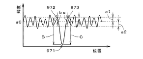
- the non-periodic luminance variation includes a downward peak, a lower peak, and upward peaks, a first upper peak and a second upper peak, adjacent to both sides of the lower peak.
- a1 and a2 be the upward half-amplitude and the downward half-amplitude of the luminance variation in the at least one luminance profile
- b the luminance difference between the first upper peak and the background luminance a0
- b the luminance difference between the second upper peak
- c the luminance difference from the background luminance a0.
- the aperiodic defect determination unit corresponds to the aperiodic luminance fluctuation when b and c in the aperiodic luminance fluctuation are less than or equal to Max (a1, a2) indicating the larger one of a1 and a2 If the aperiodic defect is determined to be the first aperiodic defect, and at least one of b and c is greater than Max(a1, a2), the aperiodicity corresponding to the aperiodic luminance variation The defect is determined to be the second aperiodic defect.
- An inspection apparatus includes an object holding unit that holds an object, an auxiliary member holding unit that holds a sheet-like or plate-like imaging auxiliary member parallel to the object, and an observation light and an illumination unit that illuminates the object, and an illumination unit that is arranged on the opposite side of the object with the imaging auxiliary member interposed therebetween, has an optical axis parallel to the normal direction of the object, and transmits the object an image pickup unit that picks up an image formed on the image pickup auxiliary member by the observation light that has been observed to acquire a picked-up image, and a distance between the image pickup auxiliary member and the image pickup unit in the optical axis direction of the image pickup unit In this state, the imaging auxiliary member and the imaging unit are moved relative to the object in the optical axis direction of the lighting unit, and the imaging auxiliary member and the object are moved in the optical axis direction of the lighting unit.
- a movement mechanism for changing the projection distance which is the distance between the and a control unit that acquires a plurality of different captured images.
- the defects detectable by the defect detection unit are first non-periodic defects that are scratches or deposits on the surface of the object, and second non-periodic defects that are contaminants mixed inside the object. including.
- the defect detection unit sets an inspection area linearly extending parallel to a second direction perpendicular to the first direction at a predetermined inspection position in a first direction in each of the plurality of captured images, and a profile acquisition unit that acquires a luminance profile that is the luminance change in the second direction in the region; detects an aperiodic luminance variation in the luminance profile of one of the plurality of captured images; an evaluation value calculation unit that obtains an evaluation value of luminance variation for each of the plurality of captured images; an aperiodic defect determination unit that determines that the defect is a first aperiodic defect if the evaluation value fluctuation index is equal to or less than the threshold value, and determines that the defect is a second aperiodic defect if the evaluation value variation index is greater than the threshold value; Prepare.
- the inspection apparatus can detect defects while automatically determining the types of defects.
- the inspection device measures the distance between the object and the imaging assist member in the optical axis direction of the illumination unit, and the distance between the imaging assist member and the imaging unit in the optical axis direction of the imaging unit. while maintaining the distance between the object, the imaging assist member, and the imaging unit relative to the optical axis of the illumination unit about a rotation axis perpendicular to the optical axis of the illumination unit. It further comprises a rotation mechanism that rotates and changes a measurement angle that is an angle between the optical axis of the illumination unit and the normal direction of the object.
- the imaging unit, the moving mechanism, and the rotating mechanism are controlled by the control unit, and a plurality of captured images with different projection distances are acquired at each of a plurality of measurement angles.
- the profile acquisition unit acquires a plurality of brightness profiles from the plurality of captured images for each of the plurality of measurement angles.
- the evaluation value calculation unit obtains a plurality of evaluation values of the aperiodic luminance variation from the plurality of captured images for each of the plurality of measurement angles.
- the evaluation value variation index is obtained also based on the variation of the plurality of evaluation values at each of the plurality of measurement angles.
- An inspection apparatus includes an object holding unit that holds an object, an auxiliary member holding unit that holds a sheet-like or plate-like imaging auxiliary member parallel to the object, and an observation light and an illumination unit that illuminates the object, and an illumination unit that is arranged on the opposite side of the object with the imaging auxiliary member interposed therebetween, has an optical axis parallel to the normal direction of the object, and transmits the object a distance between the object and the imaging auxiliary member in the optical axis direction of the imaging unit that captures an image formed on the imaging auxiliary member by the observation light that has been observed and acquires the captured image; and, while maintaining a distance between the imaging assist member and the imaging unit in the optical axis direction of the imaging unit, the object, the imaging assist member, and the imaging unit are arranged on the optical axis of the illumination unit.
- the inspection apparatus can detect defects while automatically determining the types of defects.
- the inspection apparatus moves the imaging assist member and the imaging unit with respect to the object while maintaining a distance between the imaging auxiliary member and the imaging unit in the optical axis direction of the imaging unit.
- the apparatus further includes a movement mechanism that relatively moves in the optical axis direction of the illumination unit and changes a projection distance, which is the distance between the imaging assist member and the object in the optical axis direction of the illumination unit.
- the illumination section includes a light source section and a lens that converts light from the light source section into the observation light that is parallel light and irradiates the object with the observation light.
- a distance between the lens and the imaging assist member in the optical axis direction of the illumination section is at least half of the focal length of the lens.
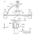
- FIG. 1 is a front view of an inspection device according to one embodiment;
- FIG. 1 is a plan view of an image acquisition device;
- FIG. 1 is a plan view of an image acquisition device;
- FIG. 1 is a plan view of an image acquisition device;
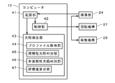
- FIG. It is a figure which shows the structure of a computer.
- 2 is a block diagram showing functions implemented by a computer;
- FIG. It is a figure which shows a manufacturing apparatus.
- FIG. 4 is a diagram showing a captured image and an inspection area;
- FIG. 4 is a diagram showing a luminance profile;
- FIG. 4 is a diagram showing a luminance profile;
- FIG. 4 is a diagram showing a captured image and an inspection area;
- FIG. 4 is a diagram showing a luminance profile;
- FIG. 4 is a diagram showing a luminance profile; It is a figure which shows the flow of defect detection.
- FIG. 4 is a diagram showing a luminance profile; It is a figure which shows an evaluation value.
- FIG. 4 is a diagram showing a luminance profile;
- FIG. 4 is a diagram showing a luminance profile; It is a front view of another inspection apparatus.
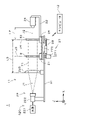
- FIG. 1 is a front view showing an inspection device 1 according to one embodiment of the present invention.
- the inspection device 1 includes an image acquisition device 11 and a computer 12 .
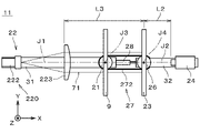
- FIG. 2 is a plan view of the image acquisition device 11.
- FIG. 1 and 2 show the X, Y and Z directions for convenience of explanation. The X, Y and Z directions are perpendicular to each other. In the examples shown in FIGS. 1 and 2, the X and Y directions are horizontal and the Z direction is vertical, but is not limited to this.
- the object 9 to be inspected is a sheet-like or plate-like translucent member manufactured while being continuously transported in a predetermined transport direction.
- the object 9 is made of thermoplastic resin, for example.
- the target object 9 can be used, for example, as a surface substrate of a liquid crystal screen, an optical film such as a 5G compatible part of a smartphone, or a substitute for a window glass of an automobile.
- the material and use of object 9 may vary.
- the object 9 is a substantially transparent member, but it may be a translucent member as long as it has translucency.
- the object 9 has, for example, a substantially rectangular shape when viewed from a direction perpendicular to the main surface. Both principal surfaces of the object 9 are substantially planes substantially parallel to each other.
- the principal surface of the object 9 is the largest surface that the object 9 has.
- the image acquisition device 11 includes an object holding unit 21, an illumination unit 22, an imaging auxiliary member 23, an imaging unit 24, an auxiliary member holding unit 26, and a rotation mechanism 27. , and a moving mechanism 28 .
- the object holding unit 21 holds the object 9.
- the object holding portion 21 is a substantially cylindrical member extending substantially parallel to the Z direction.
- the object 9 is held from below by the object holding part 21 so that the main surface is perpendicular to the XY plane.
- the normal direction of the object 9 (that is, the direction perpendicular to the main surface of the object 9) is parallel to the XY plane.
- the XY plane is a predetermined virtual plane parallel to the X direction and the Y direction.
- the direction corresponding to the transport direction during manufacturing of the target object 9, which will be described later, is parallel to the XY plane.
- the illumination section 22 includes a light source 221 , a light emitting section 222 and a lens 223 .
- illustration of the light source 221 is omitted.
- the optical axis J1 of the illumination section 22 is parallel to the X direction (that is, perpendicular to the YZ plane).
- the optical axis J1 of the illumination section 22 passes through substantially the center of the main surface of the object 9 .
- the light source 221 is, for example, an LED. A light source other than an LED may be used as the light source 221 . Light generated by the light source 221 is guided to the light emitting section 222 via an optical fiber.
- the light emitting portion 222 emits light through a pinhole. That is, the light emitting section 222 is a point light source.
- the light source 221 and the light emitting section 222 may be one unit. In the following description, the light source 221 and the light emitting section 222 are also collectively referred to as the "light source section 220".
- the light emitted from the light emitting portion 222 is converted into parallel light by the lens 223 and the object 9 is irradiated with the parallel light.
- the light emitted from the illumination unit 22 to the object 9 is also called "observation light 71".
- the light emitting portion 222, the lens 223 and the object holding portion 21 are attached to one frame 31 and relatively fixed.
- the lens 223 is a plano-convex lens in which one lens surface is flat and the other lens surface is convex.
- the lens 223 is arranged on the optical axis J ⁇ b>1 with its flat lens surface directed toward the light source unit 220 and its convex lens surface directed toward the object 9 . Note that the shape and arrangement of the lens 223 may be changed in various ways.
- the imaging assisting member 23 is a sheet-like or plate-like translucent member.
- the imaging assist member 23 is, for example, a diffusion film.
- a material other than a diffusion film may be used.
- the imaging assist member 23 has, for example, a substantially rectangular shape with substantially the same size as the object 9 when viewed in a direction perpendicular to the main surface.
- the imaging assist member 23 may be larger or smaller than the target object 9 . Further, the shape of the imaging assist member 23 can be changed variously.
- Both main surfaces of the imaging assist member 23 are substantially flat surfaces substantially parallel to each other.
- the main surface of the imaging assistance member 23 is the largest surface of the imaging assistance member 23 .
- the auxiliary member holding section 26 holds the imaging auxiliary member 23 .
- the auxiliary member holding portion 26 is a substantially cylindrical member extending substantially parallel to the Z direction.
- the imaging auxiliary member 23 is held from below by the auxiliary member holding portion 26 so that the main surface is perpendicular to the XY plane.
- the auxiliary member holding section 26 holds the imaging auxiliary member 23 parallel to the object 9 .
- the imaging assisting member 23 is held by the assisting member holding portion 26 so that its main surface is parallel to the main surface of the object 9 .
- the imaging assist member 23 is arranged at substantially the same position in the Z direction as the object 9, and substantially the entire object 9 when viewed along the normal direction of the object 9. overlaps with
- the imaging unit 24 is arranged on the opposite side of the object 9 with the imaging auxiliary member 23 interposed therebetween.
- the object 9, the imaging assisting member 23, and the imaging section 24 are arranged in this order from the (-X) side toward the (+X) direction.
- the illumination unit 22 is arranged on the ( ⁇ X) side of the object 9 .
- the optical axis J2 of the imaging unit 24 is parallel to the XY plane and parallel to the normal direction of the object 9 .
- the optical axis J2 of the imaging section 24 passes through approximately the center of the main surface of the imaging assist member 23 and approximately the center of the main surface of the object 9 .
- the imaging unit 24 is, for example, an industrial digital camera equipped with CMOS or CCD.
- the imaging unit 24 is, for example, an area camera capable of acquiring a two-dimensional image.
- the imaging unit 24 may be another type of camera.
- the illumination unit 22 irradiates the object 9 with the observation light 71 from the (-X) side.
- Observation light 71 that has passed through the object 9 is guided to the imaging assist member 23 and projected onto the imaging assist member 23 .
- the imaging unit 24 captures the image formed on the imaging auxiliary member 23 from the (+X) side of the imaging auxiliary member 23 to obtain a captured image.
- the imaging unit 24 acquires a transmission image of the object 9 transmitted through the imaging assist member 23 as a captured image. More precisely, the imaging unit 24 acquires data representing the image of the object 9 projected onto the imaging assist member 23 .
- the imaging unit 24 and the auxiliary member holding unit 26 are attached to one frame 32, and the relative position of the imaging unit 24 with respect to the auxiliary member holding unit 26 and the imaging auxiliary member 23 is fixed. . Therefore, the distance L2 between the imaging assist member 23 and the imaging section 24 in the direction in which the optical axis J2 of the imaging section 24 extends (hereinafter also referred to as "optical axis direction of the imaging section 24") is maintained constant. .
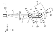
- FIG. 3 is a plan view showing a state in which the object 9 is rotated by a predetermined angle by the rotating mechanism 27.
- the rotation axis J3 passes through substantially the center of the object holder 21 in plan view.
- the rotation axis J3 passes through substantially the center of the main surface of the object 9 when viewed along the normal direction of the object 9 .
- the rotation axis J3 perpendicularly intersects the optical axis J1 of the illumination unit 22 on the object 9 .
- the angle ⁇ formed between the optical axis J1 of the illumination unit 22 and the normal direction of the object 9 in plan view (that is, when viewed along the rotation axis J3) is also called "measurement angle ⁇ ".
- the rotating mechanism 27 is a mechanism for changing the measurement angle ⁇ .
- the rotation mechanism 27 also rotates the imaging auxiliary member 23, the auxiliary member holding section 26, and the imaging section 24 integrally by rotating the frame 32 around the rotation axis J4 extending in the Z direction.
- the rotation axis J4 passes through substantially the center of the auxiliary member holding portion 26 in plan view.
- the rotation axis J3 and the rotation axis J4 are parallel to each other.
- the rotation axis J4 passes through substantially the center of the main surface of the imaging assist member 23 when viewed along the normal direction of the imaging assist member 23 . Further, the rotation axis J4 perpendicularly intersects the optical axis J1 of the illumination unit 22 and the optical axis J2 of the imaging unit 24 on the imaging auxiliary member 23 .
- the rotation direction and rotation angle of the object 9 and the imaging assist member 23 by the rotation mechanism 27 are the same. Therefore, the object 9 and the imaging assist member 23 are parallel to each other regardless of the magnitude of the measurement angle ⁇ described above. Also, the angle formed by the normal direction of the imaging assist member 23 and the optical axis J1 of the illumination unit 22 in plan view (that is, when viewed along the rotation axis J4) is equal to the measurement angle ⁇ .
- the imaging section 24 is relatively fixed with respect to the auxiliary member holding section 26 . Therefore, when the imaging auxiliary member 23 and the auxiliary member holding section 26 are rotated by the rotation mechanism 27, the imaging section 24 is also rotated.
- the optical axis J2 of the imaging unit 24 intersects the optical axis J1 of the illumination unit 22 on the rotation axis J4 regardless of the magnitude of the measurement angle ⁇ .
- the angle formed by the optical axis J2 of the imaging unit 24 and the optical axis J1 of the illumination unit 22 in plan view (that is, when viewed along the rotation axis J4) is equal to the measurement angle ⁇ .
- the distance L2 between the imaging assist member 23 and the imaging section 24 in the optical axis direction of the imaging section 24 is constant.
- the rotating mechanism 27 includes a motor 271 and a belt 272.
- the motor 271 is a rotary motor attached below the object holder 21 .
- the belt 272 is an annular member that contacts side surfaces of the object holding portion 21 and the auxiliary member holding portion 26 .
- the motor 271 rotates, the object holder 21 connected to the motor 271 rotates.
- the belt 272 also rotates due to the frictional force acting between the object holding portion 21 and the belt 272, the rotation of the object holding portion 21 is transmitted to the auxiliary member holding portion 26, and the auxiliary member holding portion 26 also holds the object. It rotates by the same angle as the part 21 .
- the moving mechanism 28 moves the imaging assist member 23 and the imaging section 24 in the X direction (that is, the optical axis direction of the illumination section 22).
- 4 is a plan view showing a state in which the imaging assist member 23 and the imaging section 24 are moved in the (+X) direction from the positions shown in FIG. 3 by the moving mechanism 28.
- FIG. In the example shown in FIG. 4 the moving mechanism 28 moves the auxiliary member holding portion 26 in the X direction, thereby moving the imaging auxiliary member 23 and the auxiliary member holding portion 26 and the auxiliary member holding portion 26 via the frame 32 .
- the fixed imaging unit 24 is moved integrally.
- the projection distance L1 is the distance in the X direction between the rotation axis J3 and the rotation axis J4.
- the moving mechanism 28 has, for example, a linear motor or an air cylinder.
- the auxiliary member holding section 26 and the imaging section 24 are integrally moved by the moving mechanism 28 . This is performed while the distance L2 (see FIG. 3) to the imaging unit 24 is kept constant.
- the moving mechanism 28 moves the auxiliary member holding unit 26 in the X direction, for example, the belt 272 of the rotating mechanism 27 expands and contracts, so that the imaging auxiliary member 23 and the auxiliary member holding unit 26 move the object 9 and The state of rotating by the same angle in synchronization with the rotation of the object holder 21 is maintained.
- the rotation of the object 9, the imaging auxiliary member 23, and the imaging unit 24 by the rotation mechanism 27 changes the distance between the object 9 and the imaging auxiliary member 23 in the X direction (that is, the projection distance L1) and the imaging unit
- the distance L2 between the imaging assist member 23 and the imaging unit 24 in the direction of the optical axis of 24 is maintained constant.
- the structures of the rotating mechanism 27 and the moving mechanism 28 are not necessarily limited to the above examples, and may be modified in various ways.
- the distance L3 is the lens It is preferably at least half the focal length of H.223. This suppresses projection of the secondary real image of the light source 221 onto the imaging assist member 23 by the lens 223 , and suppresses inclusion of the secondary real image in the captured image acquired by the imaging unit 24 .
- Observation light 71 emitted from the illumination unit 22 is reflected by the object 9 and enters the lens 223 again, and the sub real image is reflected by the lens surface of the lens 223 on the side of the light source unit 220 .
- the above-mentioned distance L3 is, in detail, a point on the optical axis J1 that serves as a reference for the focal length of the lens 223 and the position of the imaging assist member 23 on the optical axis J1 (rotational axis J4 in the above example). is the distance between
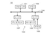
- FIG. 5 is a diagram showing the configuration of the computer 12.
- Computer 12 is a normal computer system comprising processor 101 , memory 102 , input/output unit 103 and bus 104 .
- a bus 104 is a signal circuit that connects the processor 101 , memory 102 and input/output unit 103 .
- the memory 102 stores programs and various information.
- the processor 101 executes various processes (for example, numerical calculation and image processing) while using the memory 102 and the like according to programs and the like stored in the memory 102 .
- the input/output unit 103 includes a keyboard 105 and a mouse 106 for receiving inputs from an operator, and a display 107 for displaying outputs from the processor 101 and the like.
- FIG. 6 is a block diagram showing functions realized by the computer 12.
- the computer 12 implements a storage unit 41 , a control unit 42 and a defect detection unit 43 .
- the defect detection unit 43 includes a profile acquisition unit 44 , a periodic defect determination unit 45 , an aperiodic defect determination unit 46 and an evaluation value calculation unit 47 .
- the storage unit 41 is mainly realized by the memory 102 and stores captured images and the like acquired by the imaging unit 24 .
- the control unit 42 is mainly realized by the processor 101 and controls the imaging unit 24, the rotating mechanism 27 and the moving mechanism 28.
- the defect detection unit 43 is mainly realized by the processor 101 and detects defects of the object 9 based on the captured image acquired by the imaging unit 24, as will be described later.
- FIG. 7 is a diagram showing a manufacturing device 8 that manufactures the target object 9.
- the manufacturing device 8 is a so-called extrusion molding device.
- the manufacturing device 8 includes a hopper 81, an extruder 82, a gear pump 83, a die 84, and forming rolls 85a-85c.
- Each of the forming rolls 85a to 85c has an outer diameter of, for example, 200 mm to 500 mm.
- the resin pellets and resin powder (that is, the material of the object 9) supplied from the hopper 81 are melted in the extruder 82, and the molten resin is delivered to the die 84 by the gear pump 83. Then, the film is dropped from the lower end of the die 84 and supplied between the rotating forming rolls 85a and 85b.
- the molten resin supplied from the die 84 is cooled while being pressed between the forming rolls 85a and 85b, and formed into a sheet member 90 (that is, a continuous object 9) having a predetermined thickness. It is wrapped around the surface of the roll 85b.
- the sheet member 90 passes between the forming rolls 85b and 85c and is pulled out.
- the direction along the area of the outer surfaces of the forming rolls 85b and 85c that contact the sheet member 90 and the direction in which the sheet member 90 separated from the forming roll 85c is conveyed are the conveying directions of the sheet member 90. (that is, the transport direction of the object 9 described above).
- the transport direction is indicated by an arrow with reference numeral 91 .
- the object 9 described above is obtained by cutting out a part of the sheet member 90 .
- FIG. 8 is a diagram showing the object 9.
- a reference numeral 91 is attached to an arrow indicating a direction corresponding to the conveying direction 91 in FIG.
- the direction on the object 9 corresponding to the transport direction 91 is also called "transport direction 91".
- a direction parallel to the main surface of the object 9 and perpendicular to the transport direction 91 is also called a width direction 92 . 1 and 2, width direction 92 is perpendicular to the XY plane.
- Defects in the object 9 mainly occur during the manufacturing process in the manufacturing equipment 8. Defects of the object 9 can be classified into periodic defects, which are defects that appear periodically in the transport direction 91 described above, and non-periodic defects that do not have periodicity.
- the periodic defects include striped first periodic defects, which are a plurality of streaks periodically arranged in the transport direction 91 on the object 9 .
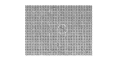
- FIG. 9 is an image of a plurality of streaks on the object 9 captured by the imaging unit 24 .
- the plurality of streaks extend substantially linearly in the width direction 92 on the object 9 .
- Each streak can also be regarded as a substantially belt-like shape whose length in the width direction 92 is longer than the width in the transport direction 91 .
- Each streak extends continuously along the width direction 92 substantially without interruption. In the example shown in FIG. 9, each streak cuts through the image along the width direction 92 .
- the period of the plurality of streaks (that is, the distance in the conveying direction 91 between two adjacent streaks) is smaller than the circumference of the outer surface of the forming roll 85b.
- the period of the plurality of streaks is 0.1% to 5% of the circumference of the outer surface of the forming roll 85b.
- the plurality of streaks are caused, for example, by the difference in rotational speed between the forming rolls 85a to 85c being out of the appropriate range.
- the plurality of streaks may extend parallel to the width direction 92, or may extend in a direction inclined to some extent with respect to the width direction.
- the angle between the direction in which the plurality of streaks extend and the width direction 92 is, for example, 0° to 10°.
- the plurality of streaks may extend strictly linearly, or may extend substantially linearly while being somewhat curved.
- a plurality of streaks may appear in exactly the same cycle in the transport direction 91, or may appear in substantially the same cycle with some deviation.
- the width direction 92 and the conveying direction 91 described above are referred to as a “first direction” and a “second direction”, respectively, the plurality of streaks extends substantially linearly along the first direction on the object 9 and also extends in the second direction. They are arranged periodically in a second direction perpendicular to the first direction.
- the above-described periodic defects further include non-streak-like second periodic defects that are different from the plurality of streaks that are the first periodic defects.
- the second periodic defects are arranged periodically in the transport direction 91 on the object 9 in substantially the same manner as the first periodic defects.
- the period in the conveying direction 91 of the second periodic defect generally tends to be larger than the period in the conveying direction 91 of the first periodic defect, but it may be smaller than the period of the first periodic defect. , may be substantially the same.
- the period of the second periodic defects in the conveying direction 91 is, for example, 0.5% to 100% of the circumferential length of the outer surface of the forming roll 85b.
- non-stripe shape means a shape that does not extend long along the width direction 92 (for example, long enough to traverse the image) and is substantially non-linear.
- Each defect included in the second periodic defect has, for example, a substantially elliptical shape or a substantially rectangular shape.
- the second periodic defect is, for example, a defect (hereinafter referred to as Also referred to as “transfer defects”).
- transfer defects For example, when there is one uneven shape on the outer surface of the forming roll 85b, the period of the transfer defect is substantially the same as the circumference of the outer surface of the forming roll 85b.
- the second periodic defect is also a defect that occurs when the sheet member 90 is not properly peeled off on a part of the outer surface of the forming roll 85b or the like when the sheet member 90 is peeled off from the outer surface of the forming roll 85b or the like (hereinafter referred to as Also called a “peeling mark”).
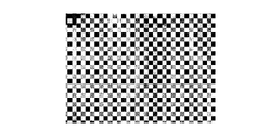
- the second periodic defect also includes defects caused by poor cooling of the sheet member 90 . Defects due to poor cooling include so-called "uneven cooling” and "uneven thickness”. Cooling unevenness is an appearance defect that may occur due to a difference in cooling rate between the vicinity of the surface of the sheet member 90 and the inside thereof when the relatively thick sheet member 90 is cooled.
- FIG. 10 is an image of uneven cooling on the object 9 captured by the imaging unit 24 .
- the second periodic defect also occurs when the molten resin falls from the die 84 between the forming rolls 85a and 85b, due to disturbances such as wind and stagnation of the molten resin on the forming rolls 85a and 85b. It also includes defects that occur when the molten resin is supplied to a position deviated from the desired drop position and improper clamping is performed (hereinafter also referred to as "drop deviation defect").
- the second periodic defect is a defect caused by periodic pulsation of the molten resin due to the meshing of the gears of the gear pump 83 (hereinafter also referred to as “pump mark”), and during kneading by the screw in the extruder 82 It also includes periodic variations in the thickness of the sheet member 90 (hereinafter also referred to as “flow marks”) caused by the resulting viscosity difference of the molten resin.
- the above-mentioned aperiodic defects include the first aperiodic defect, which is a scratch formed on the surface of the object 9 or a foreign substance (i.e., deposit) attached to the surface, and the first aperiodic defect mixed inside the object 9 and a second non-periodic defect that is a foreign object (ie, a contaminant).
- the contaminant may be wholly inside the object 9 or partially exposed from the surface of the object 9 .
- FIG. 11 is an image captured by the imaging unit 24 of a flaw (that is, a first non-periodic defect) on the surface of the object 9 . In FIG. 11, the flaw is surrounded by a dashed circle.
- the first non-periodic defect occurs when the surface of the sheet member 90 comes into contact with something after the sheet member 90 is molded in the manufacturing apparatus 8, or while the sheet member 90 molded in the manufacturing apparatus 8 is being conveyed. It is caused by foreign matter in the air adhering to the surface.
- the second non-periodic defect is caused by, for example, foreign substances in the air being mixed into the molten resin during the manufacturing of the sheet member 90 in the manufacturing apparatus 8 .
- FIG. 12 is a diagram showing an example of the defect detection flow when detecting the first periodic defect, the second periodic defect, and the non-periodic defect of the object 9 .
- the rotation mechanism 27 and the movement mechanism 28 are controlled by the control unit 42 (see FIG. 6) so as to obtain a predetermined measurement angle ⁇ and projection distance L1.
- the member 23, the auxiliary member holding section 26 and the imaging section 24 are rotated and moved.
- the object 9 is irradiated with the observation light 71 from the illumination unit 22, and the captured image is acquired by the imaging unit 24 (step S11).
- the captured image is sent from the imaging unit 24 to the computer 12 and stored in the storage unit 41 (see FIG. 6).
- the profile acquisition unit 44 is placed at a plurality of inspection positions in the direction corresponding to the width direction 92 of the object 9 (hereinafter also simply referred to as the "width direction 92").
- a plurality of inspection areas 96 are respectively set by (see FIG. 6).
- the outline of the captured image 95 and the inspection area 96 are displayed, but the illustration of defects and the like included in the captured image 95 is omitted.
- Each inspection area 96 is a rectangular strip-shaped area that extends linearly in the direction corresponding to the transport direction 91 of the object 9 (hereinafter also simply referred to as the “transport direction 91”) in the captured image 95 .
- Each inspection area 96 is preferably provided over the entire length of the captured image 95 in the transport direction 91 .
- the width of each inspection area 96 in the width direction 92 is smaller than the length in the transport direction 91 , and is, for example, 0.003% to 0.1% of the width in the width direction 92 of the captured image 95 .
- a plurality of inspection areas 96 are arranged apart from each other in the width direction 92 . In the example shown in FIG. 13 , three inspection areas 96 are arranged at both ends and the center of the captured image 95 in the width direction 92 .
- the three inspection areas 96 are preferably arranged at substantially equal intervals in the width direction 92 . Note that the number of the plurality of inspection areas 96 may be varied within a range of two or more.
- each inspection area 96 in the width direction 92 may be less than 0.003% of the width of the captured image 95 in the width direction 92 or may be greater than 0.1%.
- the plurality of inspection areas 96 do not necessarily have to be arranged apart from each other, and may be arranged continuously in the width direction 92 .
- the profile acquisition unit 44 acquires a luminance profile for each of the plurality of inspection regions 96 (step S12).
- a luminance profile is a change in luminance in the transport direction 91 in each inspection area 96 .
- FIG. 14 schematically shows luminance profiles in three inspection regions 96 arranged vertically in a captured image 95 in which a plurality of streaks exist, like the image shown in FIG. 9 .
- the horizontal axis in FIG. 14 indicates the position in the conveying direction 91, and the vertical axis indicates the luminance.
- FIG. 14 shows part of the luminance profile for each inspection area 96 . The same applies to similar drawings to be described later.
- the periodic defect determination unit 45 detects periodic luminance fluctuations from the luminance profile of each inspection area 96 (step S13).
- Periodic luminance fluctuation indicates a state in which luminance peaks 97 appear periodically in the conveying direction 91 as shown in FIG.
- Periodic luminance fluctuations are detected by performing frequency analysis such as Fourier transform on the luminance profile. Detecting periodic luminance variations may be performed by other techniques.
- step S13 if the luminance profile of each inspection area 96 does not have a relatively large luminance variation (for example, a peak that is more than a predetermined non-defective product threshold value from the average luminance of the luminance profile), the object 9 is a non-defective product. is judged.
- the period of periodic luminance fluctuations in each inspection region 96 (that is, the distance between adjacent peaks 97 on the maximum value side or minimum value side) is obtained. Calculation of the period is also performed by the above-described frequency analysis or other techniques.
- the periodic defect determination unit 45 detects a first periodic defect (that is, a plurality of It is determined that there is a streak (steps S14, S15).
- the above-described state in which the periods of periodic luminance fluctuations are the same means a state in which the periods of periodic luminance fluctuations detected from a plurality of luminance profiles are within an error range of 15% or less.
- the periodic defect determination unit 45 determines that the second periodic defect exists in the object 9 (step S14 , S16).
- the defect detection unit 43 determines periodic defects.
- the unit 45 may determine that the second periodic defect exists instead of the first periodic defect regardless of the result of step S14.
- the defect detection unit 43 detects non-periodic defects. Specifically, in each luminance profile of the captured image 95 described above, among relatively large luminance fluctuations (for example, peaks separated by a predetermined threshold or more from the average luminance of the luminance profile), the above periodic luminance fluctuations are excluded. is detected as an aperiodic luminance variation by the aperiodic defect discriminator 46 (see FIG. 6) (step S17). Then, the non-periodic luminance variation is judged to be an aperiodic defect by the non-periodic defect judging section 46 (step S18).
- steps S17 and S18 it is not always necessary to use all the brightness profiles in the plurality of inspection regions 96 of the captured image 95, and at least one brightness profile out of the plurality of brightness profiles is used.
- Aperiodic defects may be detected from.
- an inspection area 96 other than the plurality of inspection areas 96 described above may be set in the captured image 95, and non-periodic defects may be detected using the brightness profile of the other inspection area 96.
- the captured image 95 used for detecting periodic defects in steps S13-S16 is the same as the captured image 95 used for detecting non-periodic defects in steps S17-S18, but they are different.
- step S11 the captured image 95 for detecting periodic defects and the captured image 95 for detecting non-periodic defects are separately acquired, and in step S12, the inspection area 96 of each captured image 95 is inspected.
- a luminance profile may be obtained.
- the imaging unit 24 and the rotation mechanism 27 are controlled by the control unit 42, so that the captured image 95 for detecting periodic defects is acquired with the measurement angle ⁇ set to the predetermined first measurement angle.
- the captured image 95 for detecting aperiodic defects is acquired in a state where the measurement angle ⁇ is set to a predetermined second measurement angle.
- the second measured angle is an angle different from the first measured angle.
- the first measured angle is greater than the second measured angle.
- the first measured angle is between 30° and 80° and the second measured angle is between 0° and 60°.
- FIG. 16 is a diagram showing an example of the flow of defect detection when detecting the first non-periodic defect and the second non-periodic defect of the object 9.
- FIG. 13 acquisition of the captured image 95 (see FIG. 13) is performed in substantially the same manner as in step S11 described above.
- the moving mechanism 28 is controlled by the control unit 42 and the projection distance L1 is changed, the captured image 95 is acquired by the imaging unit 24 .
- Changing the projection distance L1 and acquiring the captured images 95 are repeated a predetermined number of times, whereby a plurality of captured images 95 with different projection distances L1 are acquired (step S21).
- the plurality of captured images 95 are sent from the imaging section 24 to the computer 12 and stored in the storage section 41 (see FIG. 6).
- step S21 for example, captured images 95 are acquired when the projection distance L1 is 30 mm, 50 mm, 100 mm, 150 mm, 200 mm, 250 mm, 300 mm and 350 mm.
- the projection distance L1 may be changed variously, and the number of the plurality of captured images 95 may also be changed variously within a range of two or more.
- the above-described inspection area 96 is set in each captured image 95 by the profile acquisition unit 44 .
- the number of inspection areas 96 set in each captured image 95 is one, but a plurality of inspection areas 96 may be set in each captured image 95 .
- the profile acquisition unit 44 acquires a luminance profile in the inspection area 96 of each captured image 95 (step S22).
- the evaluation value calculation unit 47 detects non-periodic luminance fluctuations in the luminance profile of one captured image 95 (step S23).
- the non-periodic luminance variations correspond to non-periodic defects (ie, first non-periodic defects or second non-periodic defects) on object 9 .
- the detection of non-periodic luminance fluctuations is performed by removing the periodic luminance fluctuations from the luminance profile and then removing relatively large luminance fluctuations from the remaining luminance fluctuations (e.g. , peaks that are more than a predetermined threshold away from the average luminance of the luminance profile).
- step S23 if there is no relatively large luminance variation in the luminance profile of the inspection area 96, the object 9 is determined to be non-defective.
- the non-periodic defect corresponding to the non-periodic luminance fluctuation is the first non-periodic defect that is a scratch or deposit on the surface of the object 9, the first non-periodic defect diffusely reflects the observation light 71. Therefore, the observation light 71 hardly enters the area corresponding to the first non-periodic defect on the imaging assist member 23 . Therefore, the aperiodic luminance variation corresponding to the first aperiodic defect is a point-like or linear (i.e., black point or black line) darker color than the surrounding part, hereinafter also referred to as "black point etc.” ). The non-periodic luminance fluctuation corresponding to the first non-periodic defect does not fluctuate significantly even if the projection distance L1 is changed.
- the non-periodic defect corresponding to the non-periodic luminance fluctuation is the second non-periodic defect which is a contaminant inside the object 9
- the resin layer surrounding the second non-periodic defect is reflected by the observation light 71 .
- the specularly reflected lights reinforce each other around the region corresponding to the second non-periodic defect on the imaging assist member 23 . Therefore, the aperiodic luminance variation corresponding to the second aperiodic defect has a substantially ring-shaped area brighter than the surrounding area between the above-mentioned black spots and the like and the surrounding area.
- the evaluation value calculation unit 47 calculates the evaluation value of the above-described aperiodic luminance fluctuation. In addition, the evaluation value calculation unit 47 detects an aperiodic luminance variation corresponding to the aperiodic luminance variation in the luminance profile of the captured image 95 other than the one captured image 95, and detects the detected aperiodic luminance Calculate the fluctuation evaluation value. In other words, the evaluation value calculator 47 obtains the evaluation value of the non-periodic luminance variation in each of the plurality of captured images 95 described above (step S24).
- the evaluation value is, for example, the difference between the downward peak 971 corresponding to the above-mentioned black point and the upward peaks 972 and 973 adjacent to both sides of the peak 971 in FIG. , divided by the distance W between peaks 972 and 973 . That is, the evaluation value is obtained as Max(A, B)/W.
- the evaluation value obtained in step S24 is not limited to that obtained by the above formula (Max(A, B)/W), and may be various as long as it has at least one of the following characteristics. may be changed to One feature of the evaluation value is that the evaluation value increases as Max(A, B), which is the difference between the downward peak 971 and the upward peaks 972 and 973, increases. Another feature of the evaluation value is that the evaluation value decreases as the distance W between the peaks 972 and 973 increases.
- the evaluation value may be (Max(A, B)) 2 /W 2 .
- the evaluation value may be Max(A, B).
- the non-periodic defect determination unit 46 obtains an evaluation value fluctuation index indicating the degree of fluctuation of the evaluation values in the plurality of captured images 95 (step S25).
- the evaluation value fluctuation index is obtained by, for example, arranging the evaluation values of aperiodic luminance fluctuations in a plurality of captured images 95 having different projection distances L1 in ascending order of the projection distance L1 as shown in FIG. It is obtained as the arithmetic mean of the differences in evaluation values (that is, the absolute value of the difference between each two adjacent evaluation values).
- the evaluation value fluctuation index obtained in step S25 increases as the degree of fluctuation in the evaluation value with respect to the fluctuation of the projection distance L1 increases, and decreases as the degree of fluctuation in the evaluation value with respect to the fluctuation in the projection distance L1 decreases. may be varied in many ways.
- the non-periodic defect is the first non-periodic defect, which is a scratch or deposit on the surface of the object 9, the non-periodic luminance variation in the luminance profile is changed by changing the projection distance L1. also does not change much.
- the aperiodic defect is a second aperiodic defect that is a contaminant inside the object 9, the aperiodic luminance variation in the luminance profile changes relatively significantly when the projection distance L1 is changed. do.
- the aperiodic defect determination unit 46 if the evaluation value fluctuation index of the aperiodic luminance fluctuation in the luminance profile is equal to or less than a predetermined threshold, the aperiodic defect corresponding to the aperiodic luminance fluctuation is determined as the first aperiodic defect It is judged to be defective (steps S26, S27). Further, when the evaluation value fluctuation index of the aperiodic luminance fluctuation in the luminance profile is larger than the threshold, the aperiodic defect corresponding to the aperiodic luminance fluctuation is determined to be the second aperiodic defect ( Steps S26, S28).
- the threshold is determined in advance and stored in the storage unit 41 based on the captured image 95 of the object 9 in which the first non-periodic defect and the second non-periodic defect are present.
- a plurality of captured images 95 corresponding to a plurality of projection distances L1 are acquired while the measurement angle ⁇ is fixed at one angle.
- a plurality of captured images 95 corresponding to ⁇ may also be acquired. If the non-periodic defect is the first non-periodic defect, which is a scratch or deposit on the surface of the object 9, the non-periodic luminance variation corresponding to the non-periodic defect is measured by changing the measurement angle ⁇ . fluctuates relatively large. On the other hand, if the aperiodic defect is a second aperiodic defect that is a contaminant inside the object 9, the aperiodic luminance variation corresponding to the aperiodic defect is not change very much.
- the magnitude of the measurement angle ⁇ may vary within the range of 0° or more and less than 90°, and the number of the plurality of captured images 95 may vary within the range of 2 or more.
- step S22 a plurality of brightness profiles are obtained from a plurality of captured images 95 with different projection distances L1 for each of the plurality of measurement angles ⁇ . Further, in steps S23 and S24, a plurality of evaluation values of aperiodic luminance fluctuations are obtained from a plurality of captured images 95 with different projection distances L1 for each of a plurality of measurement angles ⁇ .
- the evaluation value fluctuation index is obtained based on the fluctuations of a plurality of evaluation values at each measurement angle ⁇ . Specifically, first, for each of the plurality of measurement angles ⁇ , a value obtained by the same method as the evaluation value fluctuation index is defined as a “provisional fluctuation index”. Then, among a plurality of provisional fluctuation indices corresponding to a plurality of measurement angles ⁇ , a value obtained by dividing the smallest provisional fluctuation index by the largest provisional fluctuation index is acquired as an evaluation value fluctuation index.
- steps S26 and S27 when the evaluation value fluctuation index is equal to or less than a predetermined threshold (that is, when the change in aperiodic luminance fluctuation with respect to the change in the measurement angle ⁇ is relatively large), the aperiodic luminance fluctuation is dealt with.
- the non-periodic defect is determined to be the first non-periodic defect.
- the evaluation value fluctuation index of the aperiodic luminance fluctuation in the luminance profile is larger than the threshold (that is, when the change in the aperiodic luminance fluctuation with respect to the change in the measurement angle ⁇ is relatively small)
- the aperiodic luminance is determined to be the second aperiodic defect.
- the above threshold when the projection distance L1 and the measurement angle ⁇ are changed in step S21 is different from the threshold when only the projection distance L1 is changed and the measurement angle ⁇ is not changed in step S21.
- steps S11 to S18 that is, discrimination between the first periodic defect and the second periodic defect, and detection of non-periodic defects
- step S11 to S16 that is, discrimination between the first periodic defect and the second periodic defect
- steps S11 to S16 that is, discrimination between the first periodic defect and the second periodic defect
- steps S21 to S27 that is, detection of first non-periodic defects and second non-periodic defects
- defect may be performed. In this case, either steps S11 to S16 or steps S21 to S27 may be performed first.
- the inspection device 1 detects defects in the sheet-like or plate-like translucent object 9 .
- the inspection apparatus 1 includes an object holding section 21 , an auxiliary member holding section 26 , an illumination section 22 , an imaging section 24 and a defect detection section 43 .
- the object holder 21 holds the object 9 .
- the auxiliary member holding section 26 holds the sheet-like or plate-like imaging auxiliary member 23 parallel to the object 9 .
- the illumination unit 22 irradiates the object 9 with observation light 71 .
- the imaging unit 24 is arranged on the side opposite to the object 9 with the imaging assist member 23 interposed therebetween.
- the imaging unit 24 has an optical axis J2 parallel to the normal direction of the object 9, and captures an image formed on the imaging assist member 23 by the observation light 71 that has passed through the object 9 to produce a captured image 95. get.
- the defect detector 43 detects defects of the object 9 based on the captured image 95 .
- Defects that can be detected by the defect detection unit 43 include a first periodic defect and a second periodic defect.
- the first periodic defect extends linearly along the first direction (the width direction 92 in the above example) on the object 9, and the second direction perpendicular to the first direction (the transport direction in the above example) 91) are a plurality of streaks arranged periodically.
- the second periodic defect is a non-streak-like defect periodically arranged in the second direction on the object 9 .
- the defect detection unit 43 includes a profile acquisition unit 44 and a periodic defect determination unit 45 .
- the profile acquisition unit 44 sets a plurality of inspection areas 96 extending linearly in parallel to the second direction at a plurality of inspection positions in the first direction in the captured image 95 .
- the profile acquisition unit 44 acquires a plurality of luminance profiles that are luminance changes in the second direction in each of the plurality of inspection regions 96 .
- the periodic defect determination unit 45 detects periodic luminance fluctuations for each of the plurality of luminance profiles. Then, when periodic luminance fluctuations having the same cycle exist in common in a plurality of luminance profiles, the periodic defect determination unit 45 determines that a first periodic defect exists, and determines that a first periodic defect exists in one of the plurality of luminance profiles. It is determined that a second periodic defect exists when the periodic luminance variation having the same period as the periodic luminance variation present in the luminance profile does not exist in another luminance profile.
- the inspection apparatus 1 can detect periodic defects of the object 9 while automatically determining the type of the periodic defects. As a result, it is possible to accurately and efficiently adjust the manufacturing apparatus 8 (see FIG. 7) of the object 9 according to the type of periodic defect. For example, when a first periodic defect, which is a plurality of streaks, is detected as a defect of the object 9, in the manufacturing apparatus 8, by adjusting the difference in rotational speed of the forming rolls 85a to 85c, the first period sexual defects can be reduced or prevented.
- the defects that can be detected by the defect detection unit 43 further include scratches or deposits on the surface of the object 9, or non-periodic defects that are contaminants mixed inside the object 9. is preferred.
- the defect detection unit 43 detects an aperiodic luminance variation in at least one luminance profile among the plurality of luminance profiles, and an aperiodic defect determination unit 46 that determines the aperiodic luminance variation as an aperiodic defect. is preferably further provided. Thereby, in addition to discrimination of the first periodic defect and the second periodic defect described above, it is possible to automatically detect the non-periodic defect of the object 9 as well. As a result, defect inspection of the object 9 can be performed with higher accuracy.
- the inspection apparatus 1 preferably further includes the rotation mechanism 27 and the control section 42.
- the rotation mechanism 27 is configured to adjust the distance between the object 9 and the imaging assist member 23 in the optical axis direction of the illumination unit 22 (that is, the projection distance L1) and the imaging assist member 23 and the imaging assist member 23 in the optical axis direction of the imaging unit 24.
- the object 9, the imaging assist member 23, and the imaging unit 24 are rotated around the rotation axes J3 and J4 perpendicular to the optical axis J1 of the illumination unit 22 while maintaining the distance between them.
- the measurement angle ⁇ formed by the optical axis J1 of the illumination unit 22 and the normal direction of the object 9 is changed.
- the control unit 42 acquires a captured image 95 with the measurement angle ⁇ set to a predetermined first measurement angle for defect detection by the periodic defect determination unit 45. Then, for defect detection by the non-periodic defect discriminating unit 46, the captured image 95 is acquired with the measurement angle ⁇ set to a predetermined second measurement angle different from the first measurement angle.
- the periodic defect is detected based on the captured image 95 acquired at the first measurement angle suitable for the characteristics of the periodic defect, and acquired at the second measurement angle suitable for the characteristics of the non-periodic defect.
- the control unit 42 controls the imaging unit 24 and the moving mechanism 28 so that the projection distance L1 is set to the predetermined first projection distance for defect detection by the periodic defect determination unit 45.
- the captured image 95 is acquired in the state, and the captured image 95 is acquired in a state where the projection distance L1 is set to a predetermined second projection distance different from the first projection distance for defect detection by the aperiodic defect determination unit 46. You can get it. Also in this case, both periodic defects and non-periodic defects can be detected with high accuracy.
- the inspection apparatus 1 preferably further includes the moving mechanism 28 and the control section 42.
- the moving mechanism 28 moves the imaging auxiliary member 23 and the imaging unit 24 toward the object 9 while maintaining the distance between the imaging auxiliary member 23 and the imaging unit 24 in the optical axis direction of the imaging unit 24 .
- the projection distance L1 which is the distance between the imaging assist member 23 and the object 9 in the optical axis direction of the illumination unit 22 .
- the control unit 42 acquires a plurality of captured images 95 with different projection distances L1 by controlling the imaging unit 24 and the moving mechanism 28 .
- the non-periodic defects include first non-periodic defects that are scratches or deposits on the surface of the object 9 and second non-periodic defects that are contaminants mixed inside the object 9 .
- the profile acquisition unit 44 sets an inspection area 96 extending linearly in parallel to the second direction at a predetermined inspection position in the first direction, and in the inspection area 96 A luminance profile is obtained which is the luminance change in the second direction.
- the defect detector 43 further includes an evaluation value calculator 47 .
- the evaluation value calculation unit 47 detects an aperiodic luminance variation in the luminance profile of one of the plurality of captured images 95, and calculates the evaluation value of the aperiodic luminance variation in each of the plurality of captured images 95. Ask.
- the aperiodic defect determination unit 46 determines that the evaluation value fluctuation index indicating the degree of fluctuation of the evaluation value in the plurality of captured images 95 is equal to or less than a predetermined threshold value, the first aperiodic defect. It is preferable to determine that the defect is the second non-periodic defect when the evaluation value fluctuation index is larger than the threshold value. As a result, the non-periodic defect of the object 9 can be detected while automatically determining the type of the non-periodic defect.
- the inspection device 1 further includes a rotation mechanism 27.
- the rotation mechanism 27 is configured to adjust the distance between the object 9 and the imaging assist member 23 in the optical axis direction of the illumination unit 22 (that is, the projection distance L1) and the imaging assist member 23 and the imaging assist member 23 in the optical axis direction of the imaging unit 24.
- the object 9, the imaging assist member 23, and the imaging unit 24 are rotated around the rotation axes J3 and J4 perpendicular to the optical axis J1 of the illumination unit 22 while maintaining the distance between the illumination unit 22 and the illumination unit 22.
- the measurement angle ⁇ formed by the optical axis J1 of the illumination unit 22 and the normal direction of the object 9 is changed.
- the imaging unit 24, the moving mechanism 28, and the rotating mechanism 27 are controlled by the control unit 42, and a plurality of captured images 95 with different projection distances L1 are acquired at each of the plurality of measurement angles ⁇ .
- the profile acquisition unit 44 acquires a plurality of luminance profiles from the plurality of captured images 95 for each of the plurality of measurement angles ⁇ .
- the evaluation value calculation unit 47 obtains a plurality of evaluation values of the aperiodic luminance fluctuation from the plurality of captured images 95 for each of the plurality of measurement angles ⁇ . It is preferable that the evaluation value fluctuation index is obtained also based on the fluctuations of the plurality of evaluation values at each of the plurality of measurement angles ⁇ . As a result, it is possible to automatically determine the type of non-periodic defect with high accuracy.
- steps S11 to S18 that is, discrimination between the first periodic defect and the second periodic defect, and detection of non-periodic defects
- steps S21 to Only S27 that is, discrimination between the first non-periodic defect and the second non-periodic defect
- the inspection apparatus 1 for detecting defects in the sheet-like or plate-like translucent object 9 includes an object holding unit 21, an auxiliary member holding unit 26, an illumination unit 22, and an imaging unit 24. , a moving mechanism 28 , a defect detection section 43 and a control section 42 .
- the object holder 21 holds the object 9 .
- the auxiliary member holding section 26 holds the sheet-like or plate-like imaging auxiliary member 23 parallel to the object 9 .
- the illumination unit 22 irradiates the object 9 with observation light 71 .
- the imaging unit 24 is arranged on the side opposite to the object 9 with the imaging assist member 23 interposed therebetween.
- the imaging unit 24 has an optical axis J2 parallel to the normal direction of the object 9, and captures an image formed on the imaging assist member 23 by the observation light 71 that has passed through the object 9 to produce a captured image 95. get.
- the moving mechanism 28 moves the imaging auxiliary member 23 and the imaging unit 24 toward the object 9 while maintaining the distance between the imaging auxiliary member 23 and the imaging unit 24 in the optical axis direction of the imaging unit 24 .
- the projection distance L1 which is the distance between the imaging assist member 23 and the object 9 in the optical axis direction of the illumination unit 22 .
- the defect detector 43 detects defects of the object 9 based on the captured image 95 .
- the control unit 42 acquires a plurality of captured images 95 with different projection distances L1 by controlling the imaging unit 24 and the moving mechanism 28 .
- the defects that can be detected by the defect detection unit 43 are the first non-periodic defects, which are scratches or deposits on the surface of the object 9, and the second non-periodic defects, which are contaminants mixed inside the object 9. and including.
- the defect detection unit 43 includes a profile acquisition unit 44, an evaluation value calculation unit 47, and an aperiodic defect determination unit 46.
- the profile acquisition unit 44 scans each of the captured images 95 in a second direction (conveyance An inspection area 96 extending linearly parallel to the direction 91) is set.
- the profile acquisition unit 44 acquires a luminance profile that is a luminance change in the inspection area 96 in the second direction.
- the evaluation value calculation unit 47 detects an aperiodic luminance variation in the luminance profile of one of the plurality of captured images 95, and calculates the evaluation value of the aperiodic luminance variation in each of the plurality of captured images 95.
- the aperiodic defect determination unit 46 determines that the first aperiodic defect , and if the evaluation value fluctuation index is greater than the threshold, it is determined to be the second non-periodic defect.
- the non-periodic defect of the object 9 can be detected while automatically determining the type of the non-periodic defect. As a result, it is possible to efficiently adjust the manufacturing apparatus 8 (see FIG. 7) of the object 9 and remove defective products of the object 9 according to the type of non-periodic defect.
- the inspection device 1 preferably further includes the rotation mechanism 27.
- the rotation mechanism 27 is configured to adjust the distance between the object 9 and the imaging assist member 23 in the optical axis direction of the illumination unit 22 (that is, the projection distance L1) and the imaging assist member 23 and the imaging assist member 23 in the optical axis direction of the imaging unit 24.
- the object 9, the imaging assist member 23, and the imaging unit 24 are rotated around the rotation axes J3 and J4 perpendicular to the optical axis J1 of the illumination unit 22 while maintaining the distance between them.
- the measurement angle ⁇ formed by the optical axis J1 of the illumination unit 22 and the normal direction of the object 9 is changed.
- control unit 42 controls the imaging unit 24, the moving mechanism 28, and the rotating mechanism 27, and acquires a plurality of captured images 95 with different projection distances L1 at each of the plurality of measurement angles ⁇ .
- the profile acquisition unit 44 acquires a plurality of luminance profiles from the plurality of captured images 95 for each of the plurality of measurement angles ⁇ .
- the evaluation value calculation unit 47 obtains a plurality of evaluation values of the aperiodic luminance fluctuation from the plurality of captured images 95 for each of the plurality of measurement angles ⁇ . It is preferable that the evaluation value fluctuation index is obtained also based on the fluctuations of the plurality of evaluation values at each of the plurality of measurement angles ⁇ . As a result, it is possible to automatically determine the type of non-periodic defect with high accuracy.
- the inspection apparatus 1 may perform various defect inspections other than the inspections shown in steps S11 to S18 and steps S21 to S27 described above.
- the inspection apparatus 1 for detecting defects in the sheet-like or plate-like translucent object 9 includes an object holding unit 21, an auxiliary member holding unit 26, an illumination unit 22, and an imaging unit 24. , a rotation mechanism 27 and a defect detection unit 43 .
- the object holder 21 holds the object 9 .
- the auxiliary member holding section 26 holds the sheet-like or plate-like imaging auxiliary member 23 parallel to the object 9 .
- the illumination unit 22 irradiates the object 9 with observation light 71 .
- the imaging unit 24 is arranged on the side opposite to the object 9 with the imaging assist member 23 interposed therebetween.
- the imaging unit 24 has an optical axis J2 parallel to the normal direction of the object 9, and captures an image formed on the imaging assist member 23 by the observation light 71 that has passed through the object 9 to produce a captured image 95. get.
- the rotation mechanism 27 is configured to adjust the distance between the object 9 and the imaging assist member 23 in the optical axis direction of the illumination unit 22 (that is, the projection distance L1) and the imaging assist member 23 and the imaging assist member 23 in the optical axis direction of the imaging unit 24.
- the object 9, the imaging assist member 23, and the imaging unit 24 are rotated around the rotation axes J3 and J4 perpendicular to the optical axis J1 of the illumination unit 22 while maintaining the distance between them.
- the measurement angle ⁇ formed by the optical axis J1 of the illumination unit 22 and the normal direction of the object 9 is changed.
- the defect detector 43 detects defects of the object 9 based on the captured image 95 . Accordingly, it is possible to acquire the captured image 95 at the measurement angle ⁇ suitable for various types of defects to be detected. As a result, various types of defects can be detected with high accuracy.
- the inspection device 1 preferably further includes the moving mechanism 28.
- the moving mechanism 28 moves the imaging auxiliary member 23 and the imaging unit 24 to the object 9 while maintaining the distance between the imaging auxiliary member 23 and the imaging unit 24 in the optical axis direction of the imaging unit 24 .
- the projection distance L1 which is the distance between the imaging assist member 23 and the object 9 in the optical axis direction of the illumination unit 22, is changed by relative movement in the optical axis direction. Thereby, the captured image 95 can be obtained at the projection distance L1 suitable for various types of defects to be detected. As a result, various types of defects can be detected with higher accuracy.
- the method of detecting the first non-periodic defect and the second non-periodic defect of the object 9 is not limited to the examples shown in steps S21 to S27 described above, and may be variously changed.
- 19A and 19B in which there is aperiodic luminance variation it is determined whether the aperiodic luminance variation is a first aperiodic defect or a second aperiodic defect. An example of the detection method of is described.
- the non-periodic luminance fluctuations are the downward peak 971 corresponding to the above-mentioned black dots and the like, and the first peaks 971 , which are upward peaks adjacent to both sides of the lower peak 971 . and a top peak 972 and a second top peak 973 .
- the background luminance a0 is acquired by the non-periodic defect determination unit 46 (see FIG. 6).
- the background luminance a0 in FIGS. 19A and 19B is the average luminance variation (ie, average luminance) in the luminance profiles illustrated in FIGS. 19A and 19B, respectively.
- the non-periodic defect determination unit 46 acquires the upward and downward half amplitudes a1 and a2 of the luminance variation in the luminance profile.
- the background luminance a0 is the average luminance in the entire area excluding non-periodic luminance fluctuations from the luminance profile.
- the half amplitudes a1 and a2 are averages of upward and downward half amplitudes in the entire region excluding aperiodic luminance fluctuations from the luminance profile.
- the non-periodic defect determination unit 46 obtains the luminance difference b between the first upper peak 972 and the background luminance a0, and obtains the luminance difference c between the second upper peak 973 and the background luminance a0.
- the luminance differences b and c are absolute values (that is, 0 or more).
- the non-periodic defect determination unit 46 sets the luminance difference b and the luminance difference c to Max(a1, a2), which indicates the larger one of the half amplitude a1 and the half amplitude a2, as shown in FIG. 19A.
- the non-periodic defect corresponding to the non-periodic luminance variation is determined to be the first non-periodic defect if: Further, as shown in FIG. 19B, when at least one of the luminance difference b and the luminance difference c is larger than Max(a1, a2), the non-periodic defect corresponding to the non-periodic luminance variation is the second non-periodic defect. It is judged to be a periodic defect. As a result, it is possible to detect the non-periodic defect of the object 9 while automatically determining the type of the non-periodic defect with high accuracy.
- the peak luminance value of the lower peak 971 may be equal to or higher than the background luminance a0, it is preferably less than the background luminance from the viewpoint of accurately discriminating the types of non-periodic defects. That is, if the luminance difference between the lower peak 971 and the first upper peak 972 is B, and the luminance difference between the lower peak 971 and the second upper peak 973 is C, then out of (b/B) and (c/C) , at least one is preferably less than 1, more preferably both are less than 1.
- the average luminance of the luminance profile in another inspection area 96 adjacent to the inspection area 96 corresponding to the luminance profile in which non-periodic luminance fluctuations exist may be used as the background luminance a0 described above.
- the background luminance a0 may be the average luminance of the luminance profile in another inspection area 96 where it has been confirmed that there is no non-periodic luminance variation.
- the background luminance a0 may be the average luminance of the luminance profiles of non-defective objects 9 acquired in the past.
- the illumination unit 22 includes the light source unit 220 and the lens 223.
- the lens 223 converts the light from the light source unit 220 into the observation light 71, which is parallel light. 9 is preferred.
- the distance L3 between the lens 223 and the imaging assist member 23 in the optical axis direction (X direction in the above example) of the illumination unit 22 is preferably half or more of the focal length of the lens 223 .
- the structures of the rotating mechanism 27 and the moving mechanism 28 are not limited to those described above, and may be modified in various ways.
- the rotation mechanism 27 may rotate the imaging assist member 23 and the imaging unit 24 relative to the optical axis J1 of the illumination unit 22.
- the illumination unit 22, the object 9, and the object holding unit 21 may be rotated They may be rotated while maintaining their relative positions.
- the moving mechanism 28 may move the imaging assist member 23 and the imaging unit 24 relative to the object 9 in the optical axis direction of the illumination unit 22 (that is, the X direction).
- the object holders 21 may be moved in the X direction while maintaining their relative positions.
- step S13 if there is no relatively large luminance variation in the luminance profile of the inspection area 96, the object 9 is judged to be non-defective. method.
- an object that has been confirmed to be a non-defective product (hereinafter also referred to as "reference object") is measured at a predetermined measurement angle ⁇ (for example, 30°, hereinafter also referred to as "reference angle").
- ⁇ for example, 30°, hereinafter also referred to as "reference angle”
- the acquired image is stored in the storage unit 41 as a reference image.
- the luminance profile in the inspection area of the reference image is also stored in the storage unit 41 as a reference profile. It is assumed that the reference image has a plurality of streaks with density differences within the allowable range.
- the object 9 to be inspected for defects is imaged at the same measurement angle ⁇ (that is, the reference angle) as above, and the brightness profile in the inspection area 96 of the captured image 95 obtained is obtained.
- the brightness profile of the captured image 95 and the brightness profile of the reference image are compared, and the difference between the upward peak and the downward peak corresponding to the streak in both brightness profiles (that is, the density of the streak).
- the acquisition of the captured image 95 and the brightness profile is repeated while changing the measurement angle ⁇ until the difference) becomes substantially the same.
- the measurement angle ⁇ of the object 9 at which the density difference of the streak is substantially the same between the luminance profile of the captured image 95 and the reference profile is obtained, and if the measurement angle ⁇ is equal to or greater than the reference angle, the product is determined to be non-defective. If it is less than the angle, it is determined that the first periodic defect (ie, multiple streaks outside the allowable range) is present.
- Detection of the first periodic defect or the like and determination of the defect type may be performed.
- the observation light 71 does not necessarily have to be parallel light, and may be diffuse light, for example.
- diffused light is used as the observation light 71
- the size of the area on the object 9 acquired as the captured image 95 changes when the projection distance L1 changes, and the observation light 71 enters the imaging unit 24.
- the amount of light emitted also changes. Therefore, before defect detection based on the captured image 95, the captured image 95 is corrected according to the change in the size of the area and the change in the amount of light. For example, when the projection distance L1 is increased, the captured image 95 is reduced and a correction is performed to emphasize the brightness difference of the captured image 95 .
- the inspection device 1 is described as being an independent device from the manufacturing device 8, but it is not limited to this.
- each part of the sheet member 90 that is a continuous member may be set as the target object 9 and the defect inspection of the target object 9 may be performed.
- the structure of the inspection device 1 may be used for in-line inspection in the production line of the sheet member 90 .
- FIG. 20 is a front view showing an example of the configuration of an inspection device 1a used for in-line inspection.
- the target object holding unit 21 a is a conveying roller that holds the sheet member 90 and conveys it in the conveying direction 91 .
- the illumination unit 22a is arranged above the sheet member 90 (that is, the (+Z) side), and the imaging auxiliary member 23a, the auxiliary member holding unit 26a, and the imaging unit 24a are arranged below the sheet member 90 (that is, (-Z) side). side).
- the rotation mechanism 27a rotates the illumination unit 22 around a rotation axis J5 extending in the Y direction, as indicated by a chain double-dashed line.
- the imaging auxiliary member 23a, the auxiliary member holding portion 26a, and the imaging portion 24a are slid in the X direction as necessary so as to receive the observation light 71 from the illumination portion 22a.
- the moving mechanism 28a moves the imaging auxiliary member 23a, the auxiliary member holding portion 26a, and the imaging portion 24a in the Z direction as indicated by the two-dot chain line.
- the imaging auxiliary member 23a, the auxiliary member holding portion 26a, and the imaging portion 24a are slid in the X direction as necessary so as to receive the observation light 71 from the illumination portion 22a.
- the inspection apparatus 1a similarly to the above, periodic defects and non-periodic defects of the object 9 (that is, each part of the sheet member 90) can be detected while automatically discriminating the types of the defects. .
- adjustment information is sent from the computer 12a to the manufacturing apparatus 8 (see FIG. 7) according to the type of defect detected, and the manufacturing apparatus 8 is automatically adjusted so as to reduce the defect. may be broken.
- the loads and the like of the forming rolls 85a to 85c are automatically adjusted according to the characteristics such as the cycle of the first periodic defect.
- the peel mark of the second periodic defect is detected, the temperature of the forming rolls 85a to 85c, the tension of the sheet member, and the like are automatically adjusted.
- a drop deviation defect also referred to as a "first hit defect”
- the distance between the die 84 and the forming rolls 85a, 85b is automatically adjusted.
- Reference Signs List 1 1a inspection device 9 object 21, 21a object holding unit 22, 22a lighting unit 23, 23a imaging auxiliary member 24, 24a imaging unit 26, 26a auxiliary member holding unit 27, 27a rotating mechanism 28, 28a moving mechanism 42 control Section 43 Defect Detection Section 44 Profile Acquisition Section 45 Periodic Defect Discrimination Section 46 Non-periodic Defect Discrimination Section 47 Evaluation Value Calculation Section 71 Observation Light 91 Conveyance Direction 92 Width Direction 95 Captured Image 96 Inspection Area 220 Light Source Section 223 Lens J1 (Illumination optical axis J2 (of imaging unit) optical axis J3, J4, J5 rotation axis L1 projection distance S11 to S18, S21 to S27 step ⁇ measurement angle
Abstract
Description
[関連出願の参照]
本願は、2021年4月22日に出願された日本国特許出願JP2021-072442からの優先権の利益を主張し、当該出願の全ての開示は、本願に組み込まれる。 The present invention relates to an inspection apparatus for detecting defects in sheet-like or plate-like translucent objects.
[Reference to related application]
This application claims the benefit of priority from Japanese Patent Application JP2021-072442 filed on April 22, 2021, the entire disclosure of which is incorporated herein.
9 対象物
21,21a 対象物保持部
22,22a 照明部
23,23a 撮像補助部材
24,24a 撮像部
26,26a 補助部材保持部
27,27a 回転機構
28,28a 移動機構
42 制御部
43 欠陥検出部
44 プロファイル取得部
45 周期性欠陥判別部
46 非周期性欠陥判別部
47 評価値算出部
71 観察光
91 搬送方向
92 幅方向
95 撮像画像
96 検査領域
220 光源部
223 レンズ
J1 (照明部の)光軸
J2 (撮像部の)光軸
J3,J4,J5 回転軸
L1 投影距離
S11~S18,S21~S27 ステップ
θ 測定角度
Claims (11)
- シート状または板状の透光性を有する対象物の欠陥を検出する検査装置であって、
対象物を保持する対象物保持部と、
シート状または板状の撮像補助部材を前記対象物と平行に保持する補助部材保持部と、
観察光を前記対象物に照射する照明部と、
前記撮像補助部材を挟んで前記対象物とは反対側に配置され、前記対象物の法線方向に平行な光軸を有し、前記対象物を透過した前記観察光により前記撮像補助部材上に形成された像を撮像して撮像画像を取得する撮像部と、
前記撮像画像に基づいて前記対象物の欠陥を検出する欠陥検出部と、
を備え、
前記欠陥検出部により検出可能な欠陥は、
前記対象物上において第1方向に沿って直線状に延びるとともに前記第1方向に垂直な第2方向に周期的に並ぶ複数のスジである第1周期性欠陥と、
前記対象物上において前記第2方向に周期的に並ぶ非スジ状の第2周期性欠陥と、
を含み、
前記欠陥検出部は、
前記撮像画像において、前記第1方向の複数の検査位置にて前記第2方向に平行にそれぞれ直線状に延びる複数の検査領域を設定し、前記複数の検査領域のそれぞれにおける前記第2方向の輝度変化である複数の輝度プロファイルを取得するプロファイル取得部と、
前記複数の輝度プロファイルのそれぞれについて周期的輝度変動を検出し、周期が同じ周期的輝度変動が前記複数の輝度プロファイルに共通して存在する場合、第1周期性欠陥が存在すると判断し、前記複数の輝度プロファイルのうち一の輝度プロファイルに存在する周期的輝度変動と同じ周期の周期的輝度変動が他の輝度プロファイルに存在しない場合、第2周期性欠陥が存在すると判断する周期性欠陥判別部と、
を備える。 An inspection device for detecting defects in a sheet-like or plate-like translucent object,
an object holder that holds an object;
an auxiliary member holding unit that holds a sheet-like or plate-like imaging auxiliary member parallel to the object;
an illumination unit that irradiates the object with observation light;
arranged on the side opposite to the object across the imaging assist member, having an optical axis parallel to the normal direction of the object, and projected onto the imaging assist member by the observation light transmitted through the object; an imaging unit that captures the formed image to obtain a captured image;
a defect detection unit that detects defects in the object based on the captured image;
with
A defect that can be detected by the defect detection unit is
a first periodic defect that is a plurality of streaks extending linearly along a first direction on the object and periodically arranged in a second direction perpendicular to the first direction;
non-streak-like second periodic defects periodically arranged in the second direction on the object;
including
The defect detection unit is
In the captured image, a plurality of inspection areas extending linearly parallel to the second direction are set at a plurality of inspection positions in the first direction, and luminance in the second direction in each of the plurality of inspection areas a profile acquisition unit that acquires a plurality of luminance profiles that are variations;
Periodic luminance fluctuations are detected for each of the plurality of luminance profiles, and when periodic luminance fluctuations having the same period are commonly present in the plurality of luminance profiles, it is determined that a first periodic defect exists, and the plurality of a periodic defect determination unit that determines that a second periodic defect exists when a periodic luminance variation having the same period as a periodic luminance variation that exists in one luminance profile of the luminance profiles does not exist in another luminance profile; ,
Prepare. - 請求項1に記載の検査装置であって、
前記欠陥検出部により検出可能な欠陥は、前記対象物の表面上のキズもしくは付着物、または、前記対象物の内部に混入した混入物である非周期性欠陥をさらに含み、
前記欠陥検出部は、前記複数の輝度プロファイルのうち少なくとも1つの輝度プロファイルにおいて非周期的輝度変動を検出し、前記非周期的輝度変動を非周期性欠陥と判断する非周期性欠陥判別部をさらに備える。 The inspection device according to claim 1,
The defects detectable by the defect detection unit further include scratches or deposits on the surface of the object, or non-periodic defects that are contaminants mixed inside the object,
The defect detection unit further includes an aperiodic defect determination unit that detects an aperiodic luminance variation in at least one luminance profile among the plurality of luminance profiles and determines the aperiodic luminance variation as an aperiodic defect. Prepare. - 請求項2に記載の検査装置であって、
前記照明部の光軸方向における前記対象物と前記撮像補助部材との間の距離、および、前記撮像部の光軸方向における前記撮像補助部材と前記撮像部との間の距離を維持した状態で、前記対象物、前記撮像補助部材および前記撮像部を、前記照明部の光軸に垂直な回転軸を中心として前記照明部の前記光軸に対して相対的に回転させ、前記照明部の前記光軸と前記対象物の法線方向との成す角度である測定角度を変更する回転機構と、
前記撮像部および前記回転機構を制御することにより、前記周期性欠陥判別部による欠陥検出用に、前記測定角度が所定の第1測定角度とされた状態で前記撮像画像を取得させ、前記非周期性欠陥判別部による欠陥検出用に、前記測定角度が、前記第1測定角度とは異なる所定の第2測定角度とされた状態で前記撮像画像を取得させる制御部と、
をさらに備える。 The inspection device according to claim 2,
while maintaining the distance between the object and the imaging auxiliary member in the optical axis direction of the illumination unit and the distance between the imaging auxiliary member and the imaging unit in the optical axis direction of the imaging unit , the object, the imaging assist member, and the imaging unit are rotated relative to the optical axis of the illumination unit about a rotation axis perpendicular to the optical axis of the illumination unit; a rotating mechanism for changing a measurement angle, which is the angle between the optical axis and the normal direction of the object;
By controlling the imaging unit and the rotation mechanism, the captured image is acquired with the measurement angle set to a predetermined first measurement angle for defect detection by the periodic defect determination unit, and the non-periodic a control unit for acquiring the captured image in a state in which the measurement angle is set to a predetermined second measurement angle different from the first measurement angle for defect detection by the defect determination unit;
further provide. - 請求項2に記載の検査装置であって、
前記撮像部の光軸方向における前記撮像補助部材と前記撮像部との間の距離を維持した状態で、前記撮像補助部材および前記撮像部を前記対象物に対して前記照明部の光軸方向に相対移動し、前記照明部の光軸方向における前記撮像補助部材と前記対象物との間の距離である投影距離を変更する移動機構と、
前記撮像部および前記移動機構を制御することにより、前記投影距離が異なる複数の撮像画像を取得させる制御部と、
をさらに備え、
前記非周期性欠陥は、
前記対象物の表面上のキズまたは付着物である第1非周期性欠陥と、
前記対象物の内部に混入した混入物である第2非周期性欠陥と、
を含み、
前記プロファイル取得部は、前記複数の撮像画像のそれぞれにおいて、前記第1方向の所定の検査位置にて前記第2方向に平行に直線状に延びる検査領域を設定し、前記検査領域における前記第2方向の輝度変化である輝度プロファイルを取得し、
前記欠陥検出部は、前記複数の撮像画像のうち一の撮像画像の前記輝度プロファイルにおいて非周期的輝度変動を検出し、前記非周期的輝度変動の評価値を前記複数の撮像画像のそれぞれにおいて求める評価値算出部をさらに備え、
前記非周期性欠陥判別部は、前記非周期的輝度変動について、前記複数の撮像画像における評価値の変動の程度を示す評価値変動指数が所定の閾値以下である場合、前記第1非周期性欠陥であると判断し、前記評価値変動指数が前記閾値よりも大きい場合、前記第2非周期性欠陥であると判断する。 The inspection device according to claim 2,
while maintaining the distance between the imaging assist member and the imaging unit in the optical axis direction of the imaging unit; a moving mechanism that relatively moves and changes a projection distance, which is the distance between the imaging assist member and the object in the optical axis direction of the illumination unit;
a control unit that acquires a plurality of captured images with different projection distances by controlling the imaging unit and the moving mechanism;
further comprising
The aperiodic defect is
A first non-periodic defect that is a scratch or deposit on the surface of the object;
a second non-periodic defect that is a contaminant mixed inside the object;
including
The profile acquisition unit sets an inspection area linearly extending parallel to the second direction at a predetermined inspection position in the first direction in each of the plurality of captured images, and sets the second inspection area in the inspection area. Get the luminance profile, which is the luminance change in the direction,
The defect detection unit detects an aperiodic luminance variation in the luminance profile of one of the plurality of captured images, and obtains an evaluation value of the aperiodic luminance variation in each of the plurality of captured images. further comprising an evaluation value calculation unit,
With respect to the aperiodic luminance fluctuation, the aperiodic defect determination unit determines that the first aperiodicity It is determined that the defect is a defect, and if the evaluation value variation index is greater than the threshold value, the defect is determined to be the second non-periodic defect. - 請求項4に記載の検査装置であって、
前記照明部の光軸方向における前記対象物と前記撮像補助部材との間の距離、および、前記撮像部の光軸方向における前記撮像補助部材と前記撮像部との間の距離を維持した状態で、前記対象物、前記撮像補助部材および前記撮像部を、前記照明部の光軸に垂直な回転軸を中心として前記照明部の前記光軸に対して相対的に回転させ、前記照明部の前記光軸と前記対象物の法線方向との成す角度である測定角度を変更する回転機構をさらに備え、
前記制御部により前記撮像部、前記移動機構および前記回転機構が制御され、複数の測定角度のそれぞれにおいて、前記投影距離が異なる複数の撮像画像が取得され、
前記プロファイル取得部により、前記複数の測定角度のそれぞれについて、前記複数の撮像画像から複数の輝度プロファイルが取得され、
前記評価値算出部により、前記複数の測定角度のそれぞれについて、前記複数の撮像画像から前記非周期的輝度変動の複数の評価値が求められ、
前記評価値変動指数は、前記複数の測定角度のそれぞれにおける前記複数の評価値の変動にも基づいて求められる。 The inspection device according to claim 4,
while maintaining the distance between the object and the imaging auxiliary member in the optical axis direction of the illumination unit and the distance between the imaging auxiliary member and the imaging unit in the optical axis direction of the imaging unit , the object, the imaging assist member, and the imaging unit are rotated relative to the optical axis of the illumination unit about a rotation axis perpendicular to the optical axis of the illumination unit; Further comprising a rotation mechanism for changing the measurement angle, which is the angle between the optical axis and the normal direction of the object,
The imaging unit, the moving mechanism, and the rotating mechanism are controlled by the control unit, and a plurality of captured images with different projection distances are acquired at each of a plurality of measurement angles,
the profile acquisition unit acquires a plurality of luminance profiles from the plurality of captured images for each of the plurality of measurement angles;
The evaluation value calculation unit obtains a plurality of evaluation values of the aperiodic luminance variation from the plurality of captured images for each of the plurality of measurement angles,
The evaluation value variation index is obtained also based on the variation of the plurality of evaluation values at each of the plurality of measurement angles. - 請求項2に記載の検査装置であって、
前記非周期性欠陥は、
前記対象物の表面上のキズまたは付着物である第1非周期性欠陥と、
前記対象物の内部に混入した混入物である第2非周期性欠陥と、
を含み、
前記非周期的輝度変動は、
下向きのピークである下ピークと、
前記下ピークの両側に隣接する上向きのピークである第1上ピークおよび第2上ピークと、
を含み、
前記少なくとも1つの輝度プロファイルにおける輝度変動の上向きの片振幅および下向きの片振幅をそれぞれa1およびa2とし、前記第1上ピークと背景輝度a0との輝度差をbとし、前記第2上ピークと前記背景輝度a0との輝度差をcとして、
前記非周期性欠陥判別部は、前記非周期的輝度変動におけるbおよびcが、a1およびa2のうち大きい方を示すMax(a1,a2)以下である場合、前記非周期的輝度変動に対応する非周期性欠陥を前記第1非周期性欠陥であると判断し、bおよびcのうち少なくとも一方が、Max(a1,a2)よりも大きい場合、前記非周期的輝度変動に対応する非周期性欠陥を前記第2非周期性欠陥であると判断する。 The inspection device according to claim 2,
The aperiodic defect is
A first non-periodic defect that is a scratch or deposit on the surface of the object;
a second non-periodic defect that is a contaminant mixed inside the object;
including
The aperiodic luminance variation is
a lower peak, which is a downward peak;
a first upper peak and a second upper peak, which are upward peaks adjacent to both sides of the lower peak;
including
Let a1 and a2 be the upward half-amplitude and the downward half-amplitude of the luminance variation in the at least one luminance profile, let b be the luminance difference between the first upper peak and the background luminance a0, and let b be the luminance difference between the second upper peak and the Assuming that the luminance difference from the background luminance a0 is c,
The aperiodic defect determination unit corresponds to the aperiodic luminance fluctuation when b and c in the aperiodic luminance fluctuation are less than or equal to Max (a1, a2) indicating the larger one of a1 and a2 If the aperiodic defect is determined to be the first aperiodic defect, and at least one of b and c is greater than Max(a1, a2), the aperiodicity corresponding to the aperiodic luminance variation The defect is determined to be the second aperiodic defect. - シート状または板状の透光性を有する対象物の欠陥を検出する検査装置であって、
対象物を保持する対象物保持部と、
シート状または板状の撮像補助部材を前記対象物と平行に保持する補助部材保持部と、
観察光を前記対象物に照射する照明部と、
前記撮像補助部材を挟んで前記対象物とは反対側に配置され、前記対象物の法線方向に平行な光軸を有し、前記対象物を透過した前記観察光により前記撮像補助部材上に形成された像を撮像して撮像画像を取得する撮像部と、
前記撮像部の光軸方向における前記撮像補助部材と前記撮像部との間の距離を維持した状態で、前記撮像補助部材および前記撮像部を前記対象物に対して前記照明部の光軸方向に相対移動し、前記照明部の光軸方向における前記撮像補助部材と前記対象物との間の距離である投影距離を変更する移動機構と、
前記撮像画像に基づいて前記対象物の欠陥を検出する欠陥検出部と、
前記撮像部および前記移動機構を制御することにより、前記投影距離が異なる複数の撮像画像を取得させる制御部と、
を備え、
前記欠陥検出部により検出可能な欠陥は、
前記対象物の表面上のキズまたは付着物である第1非周期性欠陥と、
前記対象物の内部に混入した混入物である第2非周期性欠陥と、
を含み、
前記欠陥検出部は、
前記複数の撮像画像のそれぞれにおいて、第1方向の所定の検査位置にて前記第1方向に垂直な第2方向に平行に直線状に延びる検査領域を設定し、前記検査領域における前記第2方向の輝度変化である輝度プロファイルを取得するプロファイル取得部と、
前記複数の撮像画像のうち一の撮像画像の前記輝度プロファイルにおいて非周期的輝度変動を検出し、前記非周期的輝度変動の評価値を前記複数の撮像画像のそれぞれにおいて求める評価値算出部と、
前記非周期的輝度変動について、前記複数の撮像画像における評価値の変動の程度を示す評価値変動指数が所定の閾値以下である場合、第1非周期性欠陥であると判断し、前記評価値変動指数が前記閾値よりも大きい場合、第2非周期性欠陥であると判断する非周期性欠陥判別部と、
を備える。 An inspection device for detecting defects in a sheet-like or plate-like translucent object,
an object holder that holds an object;
an auxiliary member holding unit that holds a sheet-like or plate-like imaging auxiliary member parallel to the object;
an illumination unit that irradiates the object with observation light;
arranged on the side opposite to the object across the imaging assist member, having an optical axis parallel to the normal direction of the object, and projected onto the imaging assist member by the observation light transmitted through the object; an imaging unit that captures the formed image to obtain a captured image;
while maintaining the distance between the imaging assist member and the imaging unit in the optical axis direction of the imaging unit; a moving mechanism that relatively moves and changes a projection distance, which is the distance between the imaging assist member and the object in the optical axis direction of the illumination unit;
a defect detection unit that detects defects in the object based on the captured image;
a control unit that acquires a plurality of captured images with different projection distances by controlling the imaging unit and the moving mechanism;
with
A defect that can be detected by the defect detection unit is
A first non-periodic defect that is a scratch or deposit on the surface of the object;
a second non-periodic defect that is a contaminant mixed inside the object;
including
The defect detection unit is
setting an inspection area linearly extending parallel to a second direction perpendicular to the first direction at a predetermined inspection position in the first direction in each of the plurality of captured images; a profile acquisition unit that acquires a luminance profile that is a luminance change of
an evaluation value calculation unit that detects an aperiodic luminance variation in the luminance profile of one of the plurality of captured images and obtains an evaluation value of the aperiodic luminance variation in each of the plurality of captured images;
With respect to the aperiodic luminance fluctuation, if an evaluation value fluctuation index indicating the degree of fluctuation of the evaluation value in the plurality of captured images is equal to or less than a predetermined threshold value, the defect is determined to be a first aperiodic defect, and the evaluation value an aperiodic defect determination unit that determines that the defect is a second aperiodic defect when the variation index is greater than the threshold;
Prepare. - 請求項7に記載の検査装置であって、
前記照明部の光軸方向における前記対象物と前記撮像補助部材との間の距離、および、前記撮像部の光軸方向における前記撮像補助部材と前記撮像部との間の距離を維持した状態で、前記対象物、前記撮像補助部材および前記撮像部を、前記照明部の光軸に垂直な回転軸を中心として前記照明部の前記光軸に対して相対的に回転させ、前記照明部の前記光軸と前記対象物の法線方向との成す角度である測定角度を変更する回転機構をさらに備え、
前記制御部により前記撮像部、前記移動機構および前記回転機構が制御され、複数の測定角度のそれぞれにおいて、前記投影距離が異なる複数の撮像画像が取得され、
前記プロファイル取得部により、前記複数の測定角度のそれぞれについて、前記複数の撮像画像から複数の輝度プロファイルが取得され、
前記評価値算出部により、前記複数の測定角度のそれぞれについて、前記複数の撮像画像から前記非周期的輝度変動の複数の評価値が求められ、
前記評価値変動指数は、前記複数の測定角度のそれぞれにおける前記複数の評価値の変動にも基づいて求められる。 The inspection device according to claim 7,
while maintaining the distance between the object and the imaging auxiliary member in the optical axis direction of the illumination unit and the distance between the imaging auxiliary member and the imaging unit in the optical axis direction of the imaging unit , the object, the imaging assist member, and the imaging unit are rotated relative to the optical axis of the illumination unit about a rotation axis perpendicular to the optical axis of the illumination unit; Further comprising a rotation mechanism for changing the measurement angle, which is the angle between the optical axis and the normal direction of the object,
The imaging unit, the moving mechanism, and the rotating mechanism are controlled by the control unit, and a plurality of captured images with different projection distances are acquired at each of a plurality of measurement angles,
the profile acquisition unit acquires a plurality of luminance profiles from the plurality of captured images for each of the plurality of measurement angles;
The evaluation value calculation unit obtains a plurality of evaluation values of the aperiodic luminance variation from the plurality of captured images for each of the plurality of measurement angles,
The evaluation value variation index is obtained also based on the variation of the plurality of evaluation values at each of the plurality of measurement angles. - シート状または板状の透光性を有する対象物の欠陥を検出する検査装置であって、
対象物を保持する対象物保持部と、
シート状または板状の撮像補助部材を前記対象物と平行に保持する補助部材保持部と、
観察光を前記対象物に照射する照明部と、
前記撮像補助部材を挟んで前記対象物とは反対側に配置され、前記対象物の法線方向に平行な光軸を有し、前記対象物を透過した前記観察光により前記撮像補助部材上に形成された像を撮像して撮像画像を取得する撮像部と、
前記照明部の光軸方向における前記対象物と前記撮像補助部材との間の距離、および、前記撮像部の光軸方向における前記撮像補助部材と前記撮像部との間の距離を維持した状態で、前記対象物、前記撮像補助部材および前記撮像部を、前記照明部の光軸に垂直な回転軸を中心として前記照明部の前記光軸に対して相対的に回転させ、前記照明部の前記光軸と前記対象物の法線方向との成す角度である測定角度を変更する回転機構と、
前記撮像画像に基づいて前記対象物の欠陥を検出する欠陥検出部と、
を備える。 An inspection device for detecting defects in a sheet-like or plate-like translucent object,
an object holder that holds an object;
an auxiliary member holding unit that holds a sheet-like or plate-like imaging auxiliary member parallel to the object;
an illumination unit that irradiates the object with observation light;
arranged on the side opposite to the object across the imaging assist member, having an optical axis parallel to the normal direction of the object, and projected onto the imaging assist member by the observation light transmitted through the object; an imaging unit that captures the formed image to obtain a captured image;
while maintaining the distance between the object and the imaging auxiliary member in the optical axis direction of the illumination unit and the distance between the imaging auxiliary member and the imaging unit in the optical axis direction of the imaging unit , the object, the imaging assist member, and the imaging unit are rotated relative to the optical axis of the illumination unit about a rotation axis perpendicular to the optical axis of the illumination unit; a rotating mechanism for changing a measurement angle, which is the angle between the optical axis and the normal direction of the object;
a defect detection unit that detects defects in the object based on the captured image;
Prepare. - 請求項9に記載の検査装置であって、
前記撮像部の光軸方向における前記撮像補助部材と前記撮像部との間の距離を維持した状態で、前記撮像補助部材および前記撮像部を前記対象物に対して前記照明部の光軸方向に相対移動し、前記照明部の光軸方向における前記撮像補助部材と前記対象物との間の距離である投影距離を変更する移動機構をさらに備える。 The inspection device according to claim 9,
while maintaining the distance between the imaging assist member and the imaging unit in the optical axis direction of the imaging unit; A moving mechanism that relatively moves to change a projection distance, which is a distance between the imaging assist member and the object in the optical axis direction of the illumination unit, is further provided. - 請求項1ないし10のいずれか1つに記載の検査装置であって、
前記照明部は、
光源部と、
前記光源部からの光を平行光である前記観察光に変換して前記対象物に照射するレンズと、
を備え、
前記照明部の光軸方向における前記レンズと前記撮像補助部材との間の距離は、前記レンズの焦点距離の半分以上である。 The inspection device according to any one of claims 1 to 10,
The illumination unit
a light source;
a lens that converts the light from the light source unit into the observation light that is parallel light and irradiates the object;
with
A distance between the lens and the imaging assist member in the optical axis direction of the illumination section is at least half of the focal length of the lens.
Priority Applications (4)
| Application Number | Priority Date | Filing Date | Title |
|---|---|---|---|
| EP22791416.5A EP4328571A1 (en) | 2021-04-22 | 2022-03-15 | Inspection device |
| CN202280029258.7A CN117222886A (en) | 2021-04-22 | 2022-03-15 | Inspection apparatus |
| KR1020237038562A KR20230174235A (en) | 2021-04-22 | 2022-03-15 | inspection device |
| JP2023516342A JPWO2022224636A1 (en) | 2021-04-22 | 2022-03-15 |
Applications Claiming Priority (2)
| Application Number | Priority Date | Filing Date | Title |
|---|---|---|---|
| JP2021072442 | 2021-04-22 | ||
| JP2021-072442 | 2021-04-22 |
Publications (1)
| Publication Number | Publication Date |
|---|---|
| WO2022224636A1 true WO2022224636A1 (en) | 2022-10-27 |
Family
ID=83722893
Family Applications (1)
| Application Number | Title | Priority Date | Filing Date |
|---|---|---|---|
| PCT/JP2022/011654 WO2022224636A1 (en) | 2021-04-22 | 2022-03-15 | Inspection device |
Country Status (6)
| Country | Link |
|---|---|
| EP (1) | EP4328571A1 (en) |
| JP (1) | JPWO2022224636A1 (en) |
| KR (1) | KR20230174235A (en) |
| CN (1) | CN117222886A (en) |
| TW (1) | TW202242392A (en) |
| WO (1) | WO2022224636A1 (en) |
Cited By (1)
| Publication number | Priority date | Publication date | Assignee | Title |
|---|---|---|---|---|
| CN117491391A (en) * | 2023-12-29 | 2024-02-02 | 登景(天津)科技有限公司 | Glass substrate light three-dimensional health detection method and equipment based on chip calculation |
Citations (15)
| Publication number | Priority date | Publication date | Assignee | Title |
|---|---|---|---|---|
| JPS5761550U (en) * | 1980-09-17 | 1982-04-12 | ||
| JPH0723211U (en) * | 1993-10-04 | 1995-04-25 | 三菱樹脂株式会社 | Inspection device for transparent plastic plate |
| JP2001201429A (en) * | 2000-01-18 | 2001-07-27 | Mitsubishi Chemicals Corp | Method and device for inspecting defect in inspected base body |
| JP2003172707A (en) | 2001-12-05 | 2003-06-20 | Shibuya Kogyo Co Ltd | Method and device for inspecting product with antireflection film |
| US20070008522A1 (en) * | 2003-03-29 | 2007-01-11 | Pilkington Plc | Glazing inspection |
| JP2007065168A (en) * | 2005-08-30 | 2007-03-15 | Dainippon Printing Co Ltd | Substrate for color filter, inspection method thereof and inspection device |
| JP2007211092A (en) | 2006-02-08 | 2007-08-23 | Sekisui Chem Co Ltd | Method for inspection of transparent film, and transparent film |
| JP2010046798A (en) | 2008-08-19 | 2010-03-04 | Hitachi Zosen Corp | Roll molding machine and roll molding process of sheet film |
| JP2010507801A (en) * | 2006-10-27 | 2010-03-11 | セミシスコ・カンパニー・リミテッド | Glass substrate quality inspection apparatus and inspection method thereof |
| JP2010261948A (en) * | 2009-04-30 | 2010-11-18 | Corning Inc | Method and device for detecting defect in glass sheet |
| JP2012078144A (en) * | 2010-09-30 | 2012-04-19 | Kaneka Corp | Surface defect inspection device for transparent body sheet-like material |
| JP2015215183A (en) * | 2014-05-08 | 2015-12-03 | 株式会社神戸製鋼所 | Defect analysis device and defect analysis method |
| JP2015227888A (en) * | 2010-03-10 | 2015-12-17 | スリーエム イノベイティブ プロパティズ カンパニー | Application-specific repetitive defect detection in web manufacturing process |
| WO2017134958A1 (en) * | 2016-02-05 | 2017-08-10 | 東レ株式会社 | Inspection device for sheet-like objects, and inspection method for sheet-like objects |
| JP2019191112A (en) | 2018-04-27 | 2019-10-31 | 日立造船株式会社 | Image acquisition method, measurement method, and image acquisition device |
-
2022
- 2022-03-15 KR KR1020237038562A patent/KR20230174235A/en unknown
- 2022-03-15 WO PCT/JP2022/011654 patent/WO2022224636A1/en active Application Filing
- 2022-03-15 CN CN202280029258.7A patent/CN117222886A/en active Pending
- 2022-03-15 JP JP2023516342A patent/JPWO2022224636A1/ja active Pending
- 2022-03-15 EP EP22791416.5A patent/EP4328571A1/en active Pending
- 2022-03-18 TW TW111110204A patent/TW202242392A/en unknown
Patent Citations (15)
| Publication number | Priority date | Publication date | Assignee | Title |
|---|---|---|---|---|
| JPS5761550U (en) * | 1980-09-17 | 1982-04-12 | ||
| JPH0723211U (en) * | 1993-10-04 | 1995-04-25 | 三菱樹脂株式会社 | Inspection device for transparent plastic plate |
| JP2001201429A (en) * | 2000-01-18 | 2001-07-27 | Mitsubishi Chemicals Corp | Method and device for inspecting defect in inspected base body |
| JP2003172707A (en) | 2001-12-05 | 2003-06-20 | Shibuya Kogyo Co Ltd | Method and device for inspecting product with antireflection film |
| US20070008522A1 (en) * | 2003-03-29 | 2007-01-11 | Pilkington Plc | Glazing inspection |
| JP2007065168A (en) * | 2005-08-30 | 2007-03-15 | Dainippon Printing Co Ltd | Substrate for color filter, inspection method thereof and inspection device |
| JP2007211092A (en) | 2006-02-08 | 2007-08-23 | Sekisui Chem Co Ltd | Method for inspection of transparent film, and transparent film |
| JP2010507801A (en) * | 2006-10-27 | 2010-03-11 | セミシスコ・カンパニー・リミテッド | Glass substrate quality inspection apparatus and inspection method thereof |
| JP2010046798A (en) | 2008-08-19 | 2010-03-04 | Hitachi Zosen Corp | Roll molding machine and roll molding process of sheet film |
| JP2010261948A (en) * | 2009-04-30 | 2010-11-18 | Corning Inc | Method and device for detecting defect in glass sheet |
| JP2015227888A (en) * | 2010-03-10 | 2015-12-17 | スリーエム イノベイティブ プロパティズ カンパニー | Application-specific repetitive defect detection in web manufacturing process |
| JP2012078144A (en) * | 2010-09-30 | 2012-04-19 | Kaneka Corp | Surface defect inspection device for transparent body sheet-like material |
| JP2015215183A (en) * | 2014-05-08 | 2015-12-03 | 株式会社神戸製鋼所 | Defect analysis device and defect analysis method |
| WO2017134958A1 (en) * | 2016-02-05 | 2017-08-10 | 東レ株式会社 | Inspection device for sheet-like objects, and inspection method for sheet-like objects |
| JP2019191112A (en) | 2018-04-27 | 2019-10-31 | 日立造船株式会社 | Image acquisition method, measurement method, and image acquisition device |
Cited By (2)
| Publication number | Priority date | Publication date | Assignee | Title |
|---|---|---|---|---|
| CN117491391A (en) * | 2023-12-29 | 2024-02-02 | 登景(天津)科技有限公司 | Glass substrate light three-dimensional health detection method and equipment based on chip calculation |
| CN117491391B (en) * | 2023-12-29 | 2024-03-15 | 登景(天津)科技有限公司 | Glass substrate light three-dimensional health detection method and equipment based on chip calculation |
Also Published As
| Publication number | Publication date |
|---|---|
| EP4328571A1 (en) | 2024-02-28 |
| JPWO2022224636A1 (en) | 2022-10-27 |
| TW202242392A (en) | 2022-11-01 |
| KR20230174235A (en) | 2023-12-27 |
| CN117222886A (en) | 2023-12-12 |
Similar Documents
| Publication | Publication Date | Title |
|---|---|---|
| CN102023164B (en) | For detecting the apparatus and method of the local defect of transparent plate | |
| JP4511978B2 (en) | Surface flaw inspection device | |
| JP2006250715A (en) | Device and method for inspecting defect of film | |
| KR20160022044A (en) | Inspection device for optical film | |
| TW201241420A (en) | Tire shape testing device and tire shape testing method | |
| JP2012078144A (en) | Surface defect inspection device for transparent body sheet-like material | |
| US20140152808A1 (en) | Method and device for the reliable detection of material defects in transparent material | |
| WO2022224636A1 (en) | Inspection device | |
| KR102580389B1 (en) | Apparatus and method for inspecting a glass sheet | |
| JP5498708B2 (en) | Appearance inspection apparatus and resin molded product manufacturing method | |
| JP2009115715A (en) | Apparatus for measuring length of tread rubber of tire | |
| JP2008286646A (en) | Surface flaw inspection device | |
| JP2012122753A (en) | Defect examination apparatus, defect examination method and manufacturing apparatus for lens sheets | |
| TWI795552B (en) | Measuring method and measuring apparatus | |
| JP3870140B2 (en) | Driving transmission belt inspection method | |
| KR101316812B1 (en) | A inspecting apparatus of LCD panel | |
| KR102495565B1 (en) | How to inspect optical display panels for damage | |
| JPH10111252A (en) | Detecting equipment of flaw of glass plate | |
| JP2004212353A (en) | Optical inspection apparatus | |
| JP2005351825A (en) | Defect inspection device | |
| JP2010044049A (en) | Coating inspection method and coating inspection apparatus, and coating apparatus | |
| TWI819285B (en) | Inspection device of transmission optical system | |
| JP2006208065A (en) | Defect inspection device and ptp packing machine | |
| JP2008111746A (en) | Substrate inspection device and substrate inspection method | |
| KR20200097516A (en) | System and method for detecting defect of optical film |
Legal Events
| Date | Code | Title | Description |
|---|---|---|---|
| 121 | Ep: the epo has been informed by wipo that ep was designated in this application |
Ref document number: 22791416 Country of ref document: EP Kind code of ref document: A1 |
|
| WWE | Wipo information: entry into national phase |
Ref document number: 2023516342 Country of ref document: JP |
|
| ENP | Entry into the national phase |
Ref document number: 20237038562 Country of ref document: KR Kind code of ref document: A |
|
| WWE | Wipo information: entry into national phase |
Ref document number: 1020237038562 Country of ref document: KR |
|
| WWE | Wipo information: entry into national phase |
Ref document number: 2022791416 Country of ref document: EP |
|
| NENP | Non-entry into the national phase |
Ref country code: DE |
|
| ENP | Entry into the national phase |
Ref document number: 2022791416 Country of ref document: EP Effective date: 20231122 |