WO2022224350A1 - 熱交換器 - Google Patents
熱交換器 Download PDFInfo
- Publication number
- WO2022224350A1 WO2022224350A1 PCT/JP2021/016042 JP2021016042W WO2022224350A1 WO 2022224350 A1 WO2022224350 A1 WO 2022224350A1 JP 2021016042 W JP2021016042 W JP 2021016042W WO 2022224350 A1 WO2022224350 A1 WO 2022224350A1
- Authority
- WO
- WIPO (PCT)
- Prior art keywords
- heat exchanger
- heat transfer
- heat
- transfer tubes
- transfer tube
- Prior art date
- Legal status (The legal status is an assumption and is not a legal conclusion. Google has not performed a legal analysis and makes no representation as to the accuracy of the status listed.)
- Ceased
Links
Images












Classifications
-
- F—MECHANICAL ENGINEERING; LIGHTING; HEATING; WEAPONS; BLASTING
- F28—HEAT EXCHANGE IN GENERAL
- F28F—DETAILS OF HEAT-EXCHANGE AND HEAT-TRANSFER APPARATUS, OF GENERAL APPLICATION
- F28F1/00—Tubular elements; Assemblies of tubular elements
- F28F1/10—Tubular elements and assemblies thereof with means for increasing heat-transfer area, e.g. with fins, with projections, with recesses
- F28F1/12—Tubular elements and assemblies thereof with means for increasing heat-transfer area, e.g. with fins, with projections, with recesses the means being only outside the tubular element
- F28F1/24—Tubular elements and assemblies thereof with means for increasing heat-transfer area, e.g. with fins, with projections, with recesses the means being only outside the tubular element and extending transversely
- F28F1/30—Tubular elements and assemblies thereof with means for increasing heat-transfer area, e.g. with fins, with projections, with recesses the means being only outside the tubular element and extending transversely the means being attachable to the element
-
- F—MECHANICAL ENGINEERING; LIGHTING; HEATING; WEAPONS; BLASTING
- F28—HEAT EXCHANGE IN GENERAL
- F28D—HEAT-EXCHANGE APPARATUS, NOT PROVIDED FOR IN ANOTHER SUBCLASS, IN WHICH THE HEAT-EXCHANGE MEDIA DO NOT COME INTO DIRECT CONTACT
- F28D1/00—Heat-exchange apparatus having stationary conduit assemblies for one heat-exchange medium only, the media being in contact with different sides of the conduit wall, in which the other heat-exchange medium is a large body of fluid, e.g. domestic or motor car radiators
- F28D1/02—Heat-exchange apparatus having stationary conduit assemblies for one heat-exchange medium only, the media being in contact with different sides of the conduit wall, in which the other heat-exchange medium is a large body of fluid, e.g. domestic or motor car radiators with heat-exchange conduits immersed in the body of fluid
- F28D1/04—Heat-exchange apparatus having stationary conduit assemblies for one heat-exchange medium only, the media being in contact with different sides of the conduit wall, in which the other heat-exchange medium is a large body of fluid, e.g. domestic or motor car radiators with heat-exchange conduits immersed in the body of fluid with tubular conduits
- F28D1/053—Heat-exchange apparatus having stationary conduit assemblies for one heat-exchange medium only, the media being in contact with different sides of the conduit wall, in which the other heat-exchange medium is a large body of fluid, e.g. domestic or motor car radiators with heat-exchange conduits immersed in the body of fluid with tubular conduits the conduits being straight
- F28D1/0535—Heat-exchange apparatus having stationary conduit assemblies for one heat-exchange medium only, the media being in contact with different sides of the conduit wall, in which the other heat-exchange medium is a large body of fluid, e.g. domestic or motor car radiators with heat-exchange conduits immersed in the body of fluid with tubular conduits the conduits being straight the conduits having a non-circular cross-section
- F28D1/05366—Assemblies of conduits connected to common headers, e.g. core type radiators
- F28D1/05391—Assemblies of conduits connected to common headers, e.g. core type radiators with multiple rows of conduits or with multi-channel conduits combined with a particular flow pattern, e.g. multi-row multi-stage radiators
-
- F—MECHANICAL ENGINEERING; LIGHTING; HEATING; WEAPONS; BLASTING
- F28—HEAT EXCHANGE IN GENERAL
- F28F—DETAILS OF HEAT-EXCHANGE AND HEAT-TRANSFER APPARATUS, OF GENERAL APPLICATION
- F28F1/00—Tubular elements; Assemblies of tubular elements
- F28F1/10—Tubular elements and assemblies thereof with means for increasing heat-transfer area, e.g. with fins, with projections, with recesses
- F28F1/12—Tubular elements and assemblies thereof with means for increasing heat-transfer area, e.g. with fins, with projections, with recesses the means being only outside the tubular element
- F28F1/14—Tubular elements and assemblies thereof with means for increasing heat-transfer area, e.g. with fins, with projections, with recesses the means being only outside the tubular element and extending longitudinally
- F28F1/16—Tubular elements and assemblies thereof with means for increasing heat-transfer area, e.g. with fins, with projections, with recesses the means being only outside the tubular element and extending longitudinally the means being integral with the element, e.g. formed by extrusion
-
- F—MECHANICAL ENGINEERING; LIGHTING; HEATING; WEAPONS; BLASTING
- F28—HEAT EXCHANGE IN GENERAL
- F28F—DETAILS OF HEAT-EXCHANGE AND HEAT-TRANSFER APPARATUS, OF GENERAL APPLICATION
- F28F1/00—Tubular elements; Assemblies of tubular elements
- F28F1/10—Tubular elements and assemblies thereof with means for increasing heat-transfer area, e.g. with fins, with projections, with recesses
- F28F1/12—Tubular elements and assemblies thereof with means for increasing heat-transfer area, e.g. with fins, with projections, with recesses the means being only outside the tubular element
- F28F1/14—Tubular elements and assemblies thereof with means for increasing heat-transfer area, e.g. with fins, with projections, with recesses the means being only outside the tubular element and extending longitudinally
- F28F1/22—Tubular elements and assemblies thereof with means for increasing heat-transfer area, e.g. with fins, with projections, with recesses the means being only outside the tubular element and extending longitudinally the means having portions engaging further tubular elements
-
- F—MECHANICAL ENGINEERING; LIGHTING; HEATING; WEAPONS; BLASTING
- F28—HEAT EXCHANGE IN GENERAL
- F28F—DETAILS OF HEAT-EXCHANGE AND HEAT-TRANSFER APPARATUS, OF GENERAL APPLICATION
- F28F19/00—Preventing the formation of deposits or corrosion, e.g. by using filters or scrapers
- F28F19/006—Preventing deposits of ice
-
- F—MECHANICAL ENGINEERING; LIGHTING; HEATING; WEAPONS; BLASTING
- F28—HEAT EXCHANGE IN GENERAL
- F28F—DETAILS OF HEAT-EXCHANGE AND HEAT-TRANSFER APPARATUS, OF GENERAL APPLICATION
- F28F1/00—Tubular elements; Assemblies of tubular elements
- F28F1/02—Tubular elements of cross-section which is non-circular
- F28F1/022—Tubular elements of cross-section which is non-circular with multiple channels
-
- F—MECHANICAL ENGINEERING; LIGHTING; HEATING; WEAPONS; BLASTING
- F28—HEAT EXCHANGE IN GENERAL
- F28F—DETAILS OF HEAT-EXCHANGE AND HEAT-TRANSFER APPARATUS, OF GENERAL APPLICATION
- F28F1/00—Tubular elements; Assemblies of tubular elements
- F28F1/10—Tubular elements and assemblies thereof with means for increasing heat-transfer area, e.g. with fins, with projections, with recesses
- F28F1/12—Tubular elements and assemblies thereof with means for increasing heat-transfer area, e.g. with fins, with projections, with recesses the means being only outside the tubular element
- F28F1/126—Tubular elements and assemblies thereof with means for increasing heat-transfer area, e.g. with fins, with projections, with recesses the means being only outside the tubular element consisting of zig-zag shaped fins
- F28F1/128—Fins with openings, e.g. louvered fins
-
- F—MECHANICAL ENGINEERING; LIGHTING; HEATING; WEAPONS; BLASTING
- F28—HEAT EXCHANGE IN GENERAL
- F28F—DETAILS OF HEAT-EXCHANGE AND HEAT-TRANSFER APPARATUS, OF GENERAL APPLICATION
- F28F2210/00—Heat exchange conduits
- F28F2210/08—Assemblies of conduits having different features
Definitions
- the present disclosure relates to heat exchangers used in refrigeration cycle devices.
- a vertical corrugated fin heat exchanger is known as one of heat exchangers composed of a plurality of plate-like fins and flat heat transfer tubes (hereinafter referred to as flat tubes).
- a vertical corrugated fin heat exchanger is constructed by arranging flat tubes in the vertical direction (vertical direction) and joining the corrugated fins and flat tubes.
- a vertical corrugated fin heat exchanger it is common to provide corrugated fins with louvers (notches) in order to promote heat transfer and secure a drainage path (see, for example, Patent Document 1).
- the corrugated fin is composed of a corrugated plate member.
- a corrugated fin is composed of a plurality of bent portions formed by bending the plate-shaped member at regular intervals, and a plurality of fin body portions arranged between the adjacent bent portions.
- the fin main body is provided with a plurality of louvers obtained by cutting and raising a part of the plate member.
- Patent Document 1 As described above, the conventional vertical corrugated fin heat exchanger described in Patent Document 1 has the following problems.
- the condensed water and the melted frost water are discharged vertically downward along the louvers.
- the fin bodies of the corrugated fins are stacked in the vertical direction with a space between them, the fin bodies act as obstacles that impede the flow of water, slowing the discharge of condensed water and melted frost water.
- the present disclosure has been made to solve such problems, and provides a heat exchanger capable of suppressing air passage blockage due to frost formation and improving drainage performance of condensed water and melted frost water. intended to provide
- a heat exchanger includes a first heat exchanger that exchanges heat between air and a refrigerant, and is arranged in series with the first heat exchanger in a first direction that is the direction in which the air flows, a second heat exchanger for exchanging heat between the air and the refrigerant, wherein the first heat exchangers are spaced apart from each other in a second direction intersecting the first direction; a plurality of first heat transfer tubes through which the refrigerant is circulated, and the axial direction of the first heat transfer tubes extends along a third direction that intersects the first direction and the second direction, respectively and the second heat exchanger is arranged between a plurality of second heat transfer tubes spaced apart from each other in the second direction and through which the refrigerant flows, and between the plurality of second heat transfer tubes and corrugated fins provided in the second heat transfer tube, and the axial direction of the second heat transfer tube extends along the third direction.
- the first heat exchanger having no fins and having a high latent heat exchange amount in the total heat exchange amount, and the corrugated fins having the visible heat exchange amount in the total heat exchange amount.
- a second heat exchanger with a high heat exchange rate is arranged in series in the first direction.
- FIG. 1 is a circuit diagram showing an example of a refrigerant circuit that constitutes a refrigeration cycle device 1 equipped with a heat exchanger 10 according to Embodiment 1.
- FIG. 2 is a perspective view showing an example of the configuration of heat exchanger 10 shown in FIG. 1.
- FIG. 3 is a cross-sectional view showing a cross section of the heat exchanger 10 shown in FIG. 2 taken along a cross section A that is a virtual plane;
- FIG. 3 is a side sectional view showing an example of the configuration of a first heat exchanger 11 of the heat exchanger 10 shown in FIG. 2;
- FIG. 3 is a side sectional view showing an example of the configuration of a second heat exchanger 12 of the heat exchanger 10 shown in FIG.
- FIG. 2; 4 is a partially enlarged perspective view schematically showing an example of the configuration of a second heat exchanger 12 of the heat exchanger 10 according to Embodiment 1.
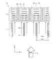
- FIG. FIG. 4 is an explanatory diagram showing a state in which frost has formed in the heat exchanger 10 shown in FIG. 3;
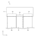
- FIG. 3 is a cross-sectional view showing a cross section of the heat exchanger 10 according to Embodiment 2 when cut along the cross section A shown in FIG. 2 ;
- FIG. 9 is an explanatory diagram showing a state in which frost has formed in the heat exchanger 10 shown in FIG. 8;
- FIG. 9 is an explanatory diagram showing a state in which frost has formed in the heat exchanger 10 shown in FIG. 8;
- FIG. 8 is an explanatory diagram showing a state in which frost has formed in the heat exchanger 10 shown in FIG. 8;
- FIG. 3 is a cross-sectional view showing a cross section of the heat exchanger 10 according to Embodiment 3 when cut along the cross section A shown in FIG. 2 ;
- FIG. 11 is a cross-sectional view showing a cross section of the heat exchanger 10 according to Embodiment 5 when cut along the cross section A shown in FIG. 2 ;
- FIG. 11 is a cross-sectional view showing a cross section of the heat exchanger 10 according to Embodiment 6 when cut along the cross section A shown in FIG. 2 ;
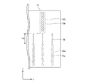
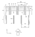
- FIG. 11 is a plan view showing the configuration of an inter-row connecting member 15 provided in a heat exchanger 10 according to Embodiment 6;
- FIG. 11 is a partial side view showing the configuration of a heat exchanger 10 according to Embodiment 6;
- FIG. 11 is a cross-sectional view showing a cross section of heat exchanger 10 according to a modification of Embodiment 6 when cut along cross section A shown in FIG. 2 ;
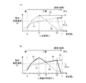
- FIG. 12 is a diagram illustrating the occurrence of dryout in the heat exchanger 10 according to Embodiment 8;
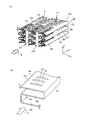
- FIG. 22 is a perspective view showing a modification of the eighth embodiment;
- FIG. 11 is a cross-sectional view showing a cross section of the heat exchanger 10 according to the ninth embodiment when cut along the cross section A shown in FIG. 2 ;
- FIG. 21 is a plan view showing the configuration of an inter-row connection member 15 of heat exchanger 10 according to Embodiment 10;
- FIG. 20 is a partial side view showing the configuration of heat exchanger 10 according to Embodiment 10;
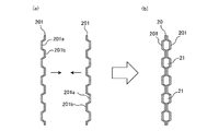
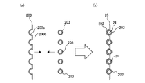
- FIG. 20 is an explanatory diagram showing a configuration of a modification of heat transfer tube 20 used in at least one of first heat exchanger 11 and second heat exchanger 12 of heat exchanger 10 according to Embodiment 11;
- FIG. 20 is an explanatory diagram showing a configuration of a modification of heat transfer tube 20 used in at least one of first heat exchanger 11 and second heat exchanger 12 of heat exchanger 10 according to Embodiment 11;
- FIG. 20 is an explanatory diagram showing a configuration of a modification of heat transfer tube 20 used in at least one of first heat exchanger 11 and second heat exchanger 12 of heat exchanger 10 according to Embodiment 11;
- FIG. 20 is an explanatory diagram showing a configuration of a modification of heat transfer tube 20 used in at least one of first heat exchanger 11 and second heat exchanger 12 of heat exchanger 10 according to Embodiment 11;
- FIG. 21 is a side cross-sectional view showing an example of the configuration of a second heat exchanger 12 of the heat exchanger 10 according to Embodiment 12;
- FIG. 1 is a circuit diagram showing an example of a refrigerant circuit that constitutes a refrigeration cycle device 1 equipped with a heat exchanger 10 according to Embodiment 1.
- the refrigeration cycle device 1 includes a compressor 2, an indoor heat exchanger 3, an indoor fan 4, an expansion device 5, a heat exchanger 10, an outdoor fan 6, and a four-way valve 7. and
- the heat exchanger 10 is sometimes called an outdoor heat exchanger.
- the refrigeration cycle device 1 has an outdoor unit and an indoor unit, for example, the compressor 2, the heat exchanger 10, the expansion device 5 and the four-way valve 7 are arranged in the outdoor unit, and the indoor heat exchanger 3 is arranged in the indoor unit. placed in
- the compressor 2, the indoor heat exchanger 3, the expansion device 5, the heat exchanger 10, and the four-way valve 7 constitute a refrigerant circuit in which refrigerant can circulate.
- a refrigerating cycle is performed in which the refrigerant circulates while changing its phase in the refrigerant circuit.
- the compressor 2 has a suction port and a discharge port, compresses the refrigerant sucked from the suction port, and discharges the compressed refrigerant from the discharge port.
- the compressor 2 is, for example, a rotary compressor, a scroll compressor, a screw compressor, or a reciprocating compressor.
- the compressor 2 may be composed of an inverter compressor. In that case, the compressor 2 may arbitrarily change the operating frequency of the motor that drives the compression mechanism of the compressor 2 by using an inverter circuit or the like to change the refrigerant discharge capacity of the compressor 2 per unit time.
- the compressor 2 is an inverter compressor, the inverter circuit is controlled by a control device (not shown).
- the control device is composed of, for example, a processing circuit such as a processor or dedicated hardware, and a memory. When the processing circuit is a processor, each function of the control device is implemented by the processor reading and executing a program stored in memory.
- the indoor heat exchanger 3 functions as a condenser when the refrigeration cycle device 1 is in heating operation, and functions as an evaporator when the refrigeration cycle device 1 is in cooling operation.
- the indoor heat exchanger 3 exchanges heat between the air in the living room supplied by the indoor fan 4 and the refrigerant flowing inside the indoor heat exchanger 3 .
- the indoor heat exchanger 3 is, for example, a fin-and-tube heat exchanger, a microchannel heat exchanger, a finless heat exchanger, a shell-and-tube heat exchanger, a heat pipe heat exchanger, or a double-tube heat exchanger. a plate heat exchanger or the like.
- the indoor fan 4 is provided for the indoor heat exchanger 3, and supplies the room air as a heat exchange fluid to the indoor heat exchanger 3.
- the indoor fan 4 is arranged facing the indoor heat exchanger 3, for example.
- the rotation speed of the indoor fan 4 is controlled by a control device (not shown).
- the expansion device 5 is a decompression device that expands and decompresses the refrigerant.
- the throttle device 5 is, for example, an expansion valve.
- the expansion device 5 may be an electric expansion valve or the like that can adjust the flow rate of the refrigerant. In that case, the diaphragm device 5 is controlled by a control device (not shown).
- the expansion device 5 may be a mechanical expansion valve employing a diaphragm as a pressure receiving portion, a capillary tube, or the like.
- the heat exchanger 10 functions as an evaporator when the refrigeration cycle device 1 is in heating operation, and functions as a condenser when the refrigeration cycle device 1 is in cooling operation.
- the heat exchanger 10 exchanges heat between the outdoor air supplied by the outdoor fan 6 and the refrigerant flowing inside the heat exchanger 10 .
- the heat exchanger 10 is composed of two heat exchangers. One of these heat exchangers is hereinafter referred to as the first heat exchanger 11 (see FIG. 2) and the other as the second heat exchanger 12 (see FIG. 2).
- the first heat exchanger 11 is, for example, a finless heat exchanger in which fins are not provided between adjacent heat transfer tubes.
- the second heat exchanger 12 is of a fin-and-tube type composed of heat transfer tubes and fins. Details of the heat exchanger 10 will be described later. In this specification, general heat exchangers in which heat transfer members such as fins are not provided between a plurality of heat transfer tubes are referred to as "finless heat exchangers.”
- the outdoor fan 6 is provided for the heat exchanger 10 and supplies outdoor air to the heat exchanger 10 .
- the outdoor fan 6 is arranged facing the heat exchanger 10, for example.
- the rotation speed of the outdoor fan 6 is controlled by a control device (not shown).
- the four-way valve 7 is a channel switching device that switches the coolant channel in the refrigeration cycle device 1 .
- the solid line indicates the state of the four-way valve 7 during heating operation
- the dashed line indicates the state of the four-way valve 7 during cooling operation and defrosting operation.
- the state of the four-way valve 7 is switched by a control device (not shown).
- the four-way valve 7 connects the discharge port of the compressor 2 and the indoor heat exchanger 3 when the refrigeration cycle device 1 is performing heating operation, and also connects the suction port of the compressor 2. It is switched to connect the mouth and the heat exchanger 10 .
- the four-way valve 7 connects the discharge port of the compressor 2 and the heat exchanger 10 when the refrigeration cycle device 1 is performing cooling operation or defrosting operation. It is switched to connect the suction port of the compressor 2 and the indoor heat exchanger 3 .
- FIG. 2 is a perspective view showing an example of the configuration of the heat exchanger 10 shown in FIG. 1.
- FIG. 3 is a cross-sectional view showing a cross section of the heat exchanger 10 shown in FIG. 2 cut along a cross section A that is a virtual plane.
- FIG. 4 is a side sectional view showing an example of the configuration of the first heat exchanger 11 of the heat exchanger 10 shown in FIG. 2.
- FIG. 5 is a side sectional view showing an example of the configuration of the second heat exchanger 12 of the heat exchanger 10 shown in FIG.
- the heat exchanger 10 is provided with a plurality of heat transfer tubes 20 through which a refrigerant flows.
- the plurality of heat transfer tubes 20 includes first heat transfer tubes 20a and second heat transfer tubes 20b.
- the cross-sectional shape of the heat transfer tubes 20 when the plurality of heat transfer tubes 20 are cut along the cross section A in FIG. 2 is a rectangular or substantially rectangular flat shape having a longitudinal direction and a lateral direction, as shown in FIG. there is At this time, the longitudinal direction of the cross-sectional shape of the heat transfer tube 20 is defined as the x direction (first direction).
- the plurality of heat transfer tubes 20 are arranged side by side at intervals.
- the arrangement direction of the plurality of heat transfer tubes 20 is the y direction (second direction).
- the lateral direction of the cross-sectional shape of the heat transfer tube 20 is the y direction.
- the axial direction of the plurality of heat transfer tubes 20, that is, the refrigerant flow direction is defined as the z direction (third direction).
- the x-, y-, and z-directions intersect each other.
- the direction in which air, which is the heat exchange fluid supplied from the outdoor fan 6 shown in FIG. 1, flows is called the "airflow direction" indicated by arrow B in FIG.
- the heat exchanger 10 is arranged such that the x direction is along the airflow direction and the z direction is along the vertical direction.
- the vertical direction is the direction of gravity indicated by arrow g in FIG.
- a cross section A which is a virtual plane in FIG. 2, is an xy plane.
- the x-direction, y-direction, and z-direction are common in each figure.
- the heat exchanger 10 is, for example, a two-row structure heat exchanger, and the first heat exchanger 11 and the , and a second heat exchanger 12 arranged on the downwind side.
- the first heat exchanger 11 is configured as a finless heat exchanger in which a plurality of first heat transfer tubes 20a are arranged independently of each other without fins.
- the second heat exchanger 12 is configured as a fin-and-tube heat exchanger including a plurality of second heat transfer tubes 20 b and corrugated fins 30 . More specifically, the second heat exchanger 12 is a vertical tube corrugated fin heat exchanger composed of second heat transfer tubes 20 b and corrugated fins 30 .
- FIG. 4 shows a side cross section of the first heat exchanger 11 cut along the yz plane.
- FIG. 4 shows a cross section when viewed in the direction of arrow B shown in FIG.
- the first heat exchanger 11 is provided with a plurality of first heat transfer tubes 20a.
- the tube axial direction of the plurality of first heat transfer tubes 20a extends along the z direction.
- the plurality of first heat transfer tubes 20a are arranged side by side at intervals along the y direction. Since the first heat exchanger 11 is a finless heat exchanger, heat transfer members such as fins are not provided between the first heat transfer tubes 20a. In a heat exchanger provided with fins, the first heat transfer tubes 20a are connected to each other through the fins.
- the first header portion 13 is provided so as to be able to distribute the refrigerant supplied from the outside to each of the first heat transfer tubes 20a of the first heat exchanger 11 .
- the refrigerant distributed by the first header portion 13 flows into the inter-row connection member 15 through each of the first heat transfer tubes 20a.
- the inter-row connection member 15 is provided so as to be able to distribute the refrigerant to each of the second heat transfer tubes 20b of the second heat exchanger 12 after joining the refrigerant.
- the first header portion 13 allows the refrigerant flowing in from the first heat transfer tubes 20a to merge and flow out to the outside.
- FIG. 5 shows a side cross section of the second heat exchanger 12 cut along the yz plane.
- FIG. 5 shows a cross-section when viewed in the direction of arrow B shown in FIG.
- the second heat exchanger 12 is provided with a plurality of second heat transfer tubes 20 b and corrugated fins 30 .
- the tube axial direction of the plurality of second heat transfer tubes 20b extends along the z direction.
- the plurality of second heat transfer tubes 20b are arranged side by side at intervals along the y direction.
- Corrugated fins 30 are arranged between the second heat transfer tubes 20b.
- One end (lower end) of the second heat transfer tube 20 b is connected to the second header portion 14 .
- the other end (upper end) of the second heat transfer tube 20 b is connected to the inter-row connection member 15 .
- the second header portion 14 can combine the refrigerants flowing in from the respective second heat transfer tubes 20b and allow them to flow out to the outside. Further, when the direction of flow of the refrigerant is reversed, the second header portion 14 can distribute the refrigerant supplied from the outside to the respective second heat transfer tubes 20b.
- the heat exchanger 10 includes the first header portion 13, the first heat transfer tubes 20a of the first heat exchanger 11, the inter-row connection members 15, the second heat transfer tubes 20b of the second heat exchanger 12, and , and second header portions 14 are connected in this order.
- the corrugated fins 30 of the second heat exchanger 12 are arranged between two adjacent second heat transfer tubes 20b.
- the corrugated fins 30 and the second heat transfer tubes 20b are joined by brazing or the like.
- the corrugated fin 30 is composed of a corrugated plate member 300 that is bent at regular intervals.
- the plate-like member 300 is a belt-like member having a constant length L1 (see FIG. 3) in the x direction and a constant thickness T (see FIG. 5).
- the corrugated fin 30 includes fin body portions 302 (see FIG. 6) spaced apart from each other along the z direction and bent portions 301 (see FIG. 6) connecting adjacent fin body portions 302 ( See FIG.
- the fin body portion 302 extends in the y direction. Also, the bent portion 301 extends in the z-direction.
- a louver 31 is provided on the fin body portion 302 .
- the louver 31 is formed by cutting and raising a portion of the plate-like member 300 that constitutes the fin body portion 302 . The louver 31 will be described later with reference to FIG.
- FIG. 2 shows the case where the heat exchanger 10 has a two-row structure, it is not limited to that case.
- the heat exchanger 10 may be configured as a heat exchanger with three or more rows depending on the heat exchange load imposed on the heat exchanger 10 .
- the heat exchanger 10 has a finless heat exchanger, a finless heat exchanger, and a fin-and-tube heat exchanger arranged in this order from the windward side.
- the heat exchangers 10 are arranged in three or more rows, one or more finless heat exchangers are arranged on the windward side, and one or more fin-and-tube heat exchangers are arranged on the leeward side.
- the first heat exchanger 11, as shown in FIGS. 3 and 4, includes a plurality of first heat transfer tubes 20a.
- each of the multiple first heat transfer tubes 20a is arranged at a preset first pitch PP1 in the y direction. Therefore, the first pitch PP1 may be called the pitch of the first heat transfer tubes 20a.
- each of the plurality of first heat transfer tubes 20a is arranged with a preset first interval PC1 in the y direction.
- the gap of the first interval PC1 serves as an air passage through which the outdoor air, which is the heat exchange fluid supplied by the outdoor fan 6, flows.
- the first interval PC1 is equal to the distance between two adjacent first heat transfer tubes 20a.
- the first interval PC1 is a value obtained by subtracting the y-direction width W1 of the first heat transfer tubes 20a from the first pitch PP1.
- the width of the air passage in the y direction of the first heat exchanger 11 is called a first interval PC1.
- the second heat exchanger 12 includes a plurality of second heat transfer tubes 20b, as shown in FIGS. 3 and 5.
- Each of the plurality of second heat transfer tubes 20b is arranged at a preset second pitch PP2 in the y direction, as shown in FIG. Therefore, the second pitch PP2 may be called the pitch of the second heat transfer tubes 20b.
- each of the plurality of second heat transfer tubes 20b is arranged with a preset second interval PC2 in the y direction.
- a corrugated fin 30 is arranged in the gap of the second interval PC2, and forms an air passage through which outdoor air, which is a heat exchange fluid supplied by the outdoor fan 6, flows.
- the second spacing PC2 is equal to the distance between two adjacent second heat transfer tubes 20b.
- the second interval PC2 is a value obtained by subtracting the y-direction width W2 of the second heat transfer tubes 20b from the second pitch PP2.
- the width of the air passage in the y direction of the second heat exchanger 12 is called a second interval PC2.
- the corrugated fin 30 has multiple fin body portions 302 extending in the y direction. As shown in FIG. 5, each of the plurality of fin body portions 302 is arranged at a preset third pitch FP2 in the z direction. Therefore, the third pitch FP2 is sometimes referred to as the pitch of the fin body portion 302. As shown in FIG. Further, as shown in FIG. 5, each of the plurality of fin body portions 302 is arranged with a preset third interval FC2 in the z direction. The space of the third interval FC2 serves as an air passage through which the outdoor air, which is the heat exchange fluid supplied by the outdoor fan 6, flows.
- a third spacing FC2 is equal to the distance between two adjacent fin body portions 302 .
- the third spacing FC2 is a value obtained by subtracting the z-direction thickness T of the fin main body 302 from the third pitch FP2.
- FC2 ⁇ PC2 an air passage of FC2 ⁇ PC2 is formed with the third spacing FC2 in the vertical direction and the second spacing PC2 in the lateral direction.
- the first heat transfer tube 20a and the second heat transfer tube 20b are, for example, flat tubes, as shown in FIG. Therefore, as described above, the first heat transfer tube 20a and the second heat transfer tube 20b have a rectangular or substantially rectangular cross-sectional shape when cut along the cross section A in FIG. .
- the x direction in which the long sides extend is referred to as the longitudinal direction of the cross section of the heat transfer tube 20
- the y direction in which the short sides extend is referred to as the lateral direction of the cross section of the heat transfer tube 20
- the heat transfer tubes 20 are arranged so that the longitudinal direction of the cross section of the heat transfer tubes 20 is along the airflow direction indicated by the arrow B for the purpose of reducing airflow resistance.
- the flattened heat transfer tube 20 can have a smaller projected area when viewed in the direction of the airflow than when a circular tube is used, the airflow resistance can be kept low.
- the first heat transfer tube 20a and the second heat transfer tube 20b may be composed of a porous flat tube provided therein with a plurality of refrigerant flow paths 21 through which the refrigerant flows.
- the plurality of refrigerant flow paths 21 are arranged side by side from one longitudinal end to the other longitudinal end of the cross section of the heat transfer tube 20 along the x direction.
- the length of the cross section of the first heat transfer tube 20a in the short direction is the length of the cross section of the second heat transfer tube 20b in the short direction (width in the y direction). W2).
- the first heat transfer tube 20a is located in front of the second heat transfer tube 20b in the airflow direction indicated by the arrow B.
- the first heat transfer tube 20a and the second heat transfer tube 20b are arranged in series in the airflow direction indicated by the arrow B, with the first heat transfer tube 20a on the windward side and the second heat transfer tube 20b on the leeward side. be.
- at least one of the first heat transfer tubes 20a of the first heat exchanger 11 is arranged so as to overlap the second heat transfer tubes 20b of the second heat exchanger 12 in the x direction.
- first heat transfer tube 20a and the second heat transfer tube 20b are made of a metal material having thermal conductivity.
- Aluminum, an aluminum alloy, copper, or a copper alloy, for example, is used as a material forming the first heat transfer tube 20a and the second heat transfer tube 20b.
- the first heat transfer tube 20a and the second heat transfer tube 20b are manufactured by an extrusion process in which a heated material is extruded through holes in a die to form the cross section shown in FIG.
- the first heat transfer tube 20a and the second heat transfer tube 20b may be manufactured by a drawing process in which a material is drawn out from a die hole and the cross section shown in FIG. 3 is formed.
- a method for manufacturing the first heat transfer tube 20 a and the second heat transfer tube 20 b can be appropriately selected according to the cross-sectional shape of the heat transfer tube 20 .
- first heat transfer tube 20a and the second heat transfer tube 20b are made of flat tubes or flat perforated tubes
- present invention is not limited to this case. That is, the first heat transfer tube 20a and the second heat transfer tube 20b may be configured from circular tubes, for example.
- the heat exchanger 10 includes, as shown in FIG. , and the second header portion 14 are connected in order to form a refrigerant channel.
- refrigerant flows in this order.
- heat exchanger 10 is functioning as a condenser, refrigerant flows in the reverse order.
- the case where the heat exchanger 10 functions as an evaporator will be described as an example.
- the direction in which the refrigerant flows when the heat exchanger 10 functions as an evaporator or a condenser is not limited to the case described here, and may be the reverse direction of the description here. good.
- the surface of the first heat transfer tube 20a is the outermost surface of the heat exchanger. Therefore, in the first heat exchanger 11, since heat conduction does not occur via the fins, the temperature of the outermost surface of the heat exchanger is close to the inner temperature of the first heat transfer tube 20a. Further, generally, when frost forms on the heat exchanger, the frost mainly adheres to the fins. However, since the first heat exchanger 11 is not provided with fins, frost adheres to the surfaces of the first heat transfer tubes 20a. The melted water of frost flows downward in the direction of gravity while running along the surfaces of the first heat transfer tubes 20a. Since the first heat transfer tubes 20a are not provided with fins, when discharging the melted frost water, there are no obstacles that block the flow of water flowing downward in the direction of gravity, and the speed of the water discharge is high.
- the corrugated fins 30 serve as the main heat exchange area.
- the second heat exchanger 12 has better heat exchange efficiency than the first heat exchanger 11 due to the provision of the corrugated fins 30 .
- the corrugated fins 30 are provided with the louvers 31 having a heat transfer promoting effect, the heat exchange efficiency is further improved.
- frost formation occurs in the second heat exchanger 12
- the frost concentrates on the louver 31 portion depending on the frost formation conditions.
- dew condensation water and melted frost water are drained while running along the louvers 31 .
- the fin body portions 302 of the corrugated fins 30 are arranged at a narrow pitch (the third pitch FP2), the fin body portions 302 become obstacles that hinder the flow of water flowing downward in the direction of gravity.
- the speed of drainage is slower than that of the first heat exchanger 11 .
- the heat exchanger 10 in order to suppress frost formation on the second heat exchanger 12, dehumidification is mainly performed in the first heat exchanger 11, and dry air is transferred to the second heat exchanger. configured to be sent to the device 12.
- frost formation in the second heat exchanger 12 can be suppressed.
- frost forms and grows the frost blocks the air passages.
- the air passages can be prevented from being blocked.
- the first heat exchanger 11 since the first heat exchanger 11 is not provided with fins, even when dew condensation or frost formation occurs, the flow of water flowing downward in the vertical direction in the discharge of dew condensation water and melted frost water There are no obstacles that block the water, and the drainage speed is fast. Therefore, the air passage between the first heat transfer tubes 20a of the first heat exchanger 11 is not blocked by condensed water or frost. A detailed description will be given below.
- the air that constitutes the airflow is moist air containing water vapor
- sensible heat exchange (cooling) and latent heat exchange (dehumidification) during cooling of the moist air that is, when the heat exchanger is used as an evaporator
- latent heat exchange dehumidification
- the relative humidity is 100% and the humidity is saturated.
- the relative humidity is usually less than 100%, ie dry bulb temperature > dew point temperature.
- the condition for latent heat exchange is that the air dew point temperature > the heat exchanger surface (water film) temperature. condenses as water droplets, films or frost.
- the condition under which sensible heat exchange (cooling) occurs is that the dry-bulb temperature of air > the surface temperature of the heat exchanger. Therefore, in the case of the relationship of dry-bulb temperature of air > surface temperature of heat exchanger > dew-point temperature of air, latent heat exchange does not occur, and only sensible heat exchange occurs. That is, the air is cooled, but not dehumidified.
- the dry-bulb temperature and the dew point temperature of moist air are similar, the lower the heat exchanger surface temperature, the higher the latent heat exchange rate in the total heat exchange rate.
- FIG. 6 is a partially enlarged perspective view schematically showing an example of the configuration of the second heat exchanger 12 of the heat exchanger 10 according to Embodiment 1.
- FIG. The corrugated fins 30 may have a corrugated shape in which a plate-like member 300 is bent into a U shape as shown in FIG. , and a wavy shape that is bent into an angular U shape.
- the corrugated fin 30 is composed of a thin plate member 300 having a thickness T. As shown in FIG. Therefore, the amount of heat transferred between the fin surfaces of the corrugated fins 30 and the air is greater than the amount of heat transferred between the outer surfaces of the second heat transfer tubes 20b and the air. As a result, the fin efficiency becomes less than 1 because a temperature gradient is generated due to the difference in the amount of heat transfer.
- the fin efficiency is the ratio between the actual amount of heat transferred from the entire surface of the corrugated fin 30 and the amount of heat transferred when all the fin surface temperatures are assumed to be equal to the fin root 303 temperature. .
- the root 303 of the fin means a portion where the corrugated fin 30 is joined to the second heat transfer tube 20b. Therefore, in some fin regions away from the root 303 of the fin, the surface temperature rises. Increases the exchange rate. Thereby, heat exchange between the refrigerant and the air is efficiently performed.
- the corrugated fin 30 is provided with a plurality of louvers 31 as shown in Figs. 6(a) and 6(b) to secure a drainage path.
- the louvers 31 are spaced apart from each other along the x-direction.
- the louver 31 also has a heat transfer promoting effect. In other words, the louver 31 promotes heat transfer on the fin side by collision between the louver 31 and the airflow and separation of the airflow.
- a method for forming the louver 31 will be specifically described.
- a U-shaped slit as shown in FIG. 6A or two parallel slits as shown in FIG. The slit penetrates the thickness T of the fin body portion 302 .
- the louver 31 is formed.
- the raised portion is hereinafter referred to as a protrusion 31a of the louver 31.
- the corrugated fin 30 is provided with the louvers 31, part of the air flowing along the fin main body 302 passes through the louvers 31 portion. That is, the louver 31 collides with the airflow, causing separation of the airflow. to flow.
- the temperature of the airflow is higher (or lower) on the side closer to the fin main body 302 , and the temperature is lower (or higher) as the distance from the fin main body 302 increases.
- frost formation - In the 2nd heat exchanger 12, frost concentrates on the louver 31 of the corrugated fin 30, if frost formation generate
- drainage - Condensed water and melted frost water are discharged downward in the direction of gravity while running along the louver 31 .
- the fin body portions 302 extend in the horizontal direction perpendicular to the gravitational direction, and are arranged at a relatively narrow third pitch FP2 in the gravitational direction as shown in FIG. Therefore, the fin main body 302 becomes an obstacle, the speed of draining water becomes slow, and water tends to stay inside the second heat exchanger 12 .
- the heat-transfer area is basically comprised only by the 1st heat-transfer pipe 20a.
- the tube outer surface of the first heat transfer tube 20a is the outermost surface of the first heat exchanger 11, and heat conduction does not occur via the fins, so the outermost surface of the first heat exchanger 11 is the first It is close to the inner temperature of the heat transfer tube 20a.
- the first heat exchanger 11 is a "complete finless heat exchanger" in which the first heat transfer tubes 20a are not provided with projections or the like, the temperature at the base of the fins, assuming the presence of fins, and the temperature at the first Since the tube surface temperature of the heat transfer tube 20a is the same, the fin efficiency is 1. That is, compared to the corrugated fin heat exchanger in which the fin efficiency is reduced due to the influence of the fins, the first heat exchanger 11 having no fins increases the ratio of the latent heat exchange amount to the total heat exchanger amount. Therefore, dehumidification of the air is efficiently performed.
- the condensed water and the melted water of frost are discharged downward in the direction of gravity while passing along the first heat transfer tubes 20a. Since the axial direction of the first heat transfer tubes 20a is arranged along the vertical direction, the condensed water and the melted frost water flow downward at a high speed due to the action of gravity. Further, since the first heat transfer tubes 20a are not provided with fins, there are no obstacles that hinder the flow of water flowing downward in the direction of gravity. Therefore, the speed of drainage is high, and water is less likely to stay in the first heat exchanger 11 .
- FIG. 7 is an explanatory diagram showing a state in which frost has formed in the heat exchanger 10 shown in FIG.
- the hatched area is the frosted area.
- the heat exchanger 10 first, in the first heat exchanger 11, heat is exchanged between the refrigerant flowing through the first heat transfer tubes 20a and the air. After that, the air flows toward the second heat exchanger 12, where heat is exchanged between the refrigerant flowing in the second heat transfer tubes 20b and the air. At this time, in the first heat exchanger 11, the latent heat exchange amount accounts for a large proportion of the total heat exchange amount, and the air is efficiently dehumidified. Therefore, the air flowing toward the second heat exchanger 12 is dry air containing little water vapor. Therefore, the relationship is: dry-bulb temperature of air > surface temperature of heat exchanger > dew point temperature of air, and latent heat exchange does not occur, only sensible heat exchange occurs.
- the air is cooled, but not dehumidified. Since dehumidification is not performed in the second heat exchanger 12, moisture in the air is not condensed as water droplets, water films, or frost on the surface of the heat exchanger. Since the first heat exchanger 11 dehumidifies, moisture in the air is condensed on the surface of the heat exchanger as water droplets, a water film, or frost. The airway is not blocked. In addition, since dry air is supplied to the second heat exchanger 12 and no dehumidification is performed, dew condensation or frost formation hardly occurs. Therefore, in the heat exchanger 10, as shown in FIG. 3, normally, both the first heat exchanger 11 and the second heat exchanger 12 do not block the air passages due to condensation or frost.
- frost formation may occur depending on the environment in which the heat exchanger 10 is arranged or the operating state of the heat exchanger 10.
- the formation of frost on the first heat exchanger 11 is not considered.
- the plurality of first heat transfer tubes 20a forming the first heat exchanger 11 are positioned in front of the second heat transfer tubes 20b forming the second heat exchanger 12 in the airflow direction. Therefore, the air flowing toward the second heat exchanger 12 is more frosted on the windward side of the corrugated fins 30 where the difference between the dew point temperature and the heat exchanger surface temperature is large.
- Embodiment 1 since the air dehumidified in the first heat exchanger 11 flows toward the second heat exchanger 12, the frost on the second heat exchanger 12 is thin and the air passage is completely closed. will not be Therefore, an increase in airflow resistance is suppressed, and a decrease in air volume can be suppressed. Therefore, an increase in load on the outdoor fan 6 can also be suppressed.
- the first heat exchanger 11 (finless heat exchanger on the windward side) has a latent heat
- the ratio of the exchange amount is large, and it is possible to dehumidify efficiently.
- the amount of dew condensation or frost formation in the second heat exchanger 12 (corrugated fin heat exchanger on the rear row side) is relatively reduced, and the air passage is blocked. Containment and wastewater load can be reduced. Therefore, in the second heat exchanger 12, the ratio of the sensible heat exchange amount to the total heat exchange amount is large, and heat exchange between the refrigerant and the air is efficiently performed.
- the first heat exchanger 11 is arranged in the front row and the second heat exchanger 12 is arranged in the rear row in the direction of the airflow. Therefore, the heat exchanger 10 as a whole can suppress blockage of air passages due to frost formation, and can improve drainage performance of dew condensation water and melted frost water. As a result, the heat exchanger 10 as a whole can perform heat exchange efficiently.
- the heat exchanger 10 as a whole can suppress the blockage of the air passage due to frost formation, depending on the operating conditions of the refrigeration cycle device 1, there is almost no need to perform the defrosting operation. The number of times it is performed can be reduced. In other words, the continuous heating operation can be maintained for a long period of time, and the discomfort caused by the decrease in the indoor temperature caused by the conventional defrosting operation can be eliminated, and the comfort of the indoor air-conditioned space can be improved.
- the inter-row connection member 15 which is a member that connects between the first heat transfer tubes 20a in the front row and the second heat transfer tubes 20b in the back row, can be integrally formed.
- the second heat exchanger 12 is configured by, for example, a fin-and-tube heat exchanger in which tubes are placed horizontally, the longitudinal direction of the header of the second heat exchanger 12 is the same as the longitudinal direction of the header of the first heat exchanger 11.
- the inter-row connecting member 15 cannot be integrally formed because it will be different.
- FIG. 8 is a cross-sectional view showing a cross section of the heat exchanger 10 according to Embodiment 2 when cut along the cross section A shown in FIG. 9 and 10 are explanatory diagrams showing a state in which frost has formed in the heat exchanger 10 shown in FIG.
- hatched areas are regions where frost formation occurs.
- changes from the first embodiment will be mainly described, and descriptions of the same configurations, operations, and effects as those of the first embodiment will be omitted.
- the first heat transfer tube 20a and the second heat transfer tube 20b are arranged in series in the airflow direction, that is, in the x direction.
- the first heat transfer tubes 20a and the second heat transfer tubes 20b are arranged with a deviation without overlapping. Therefore, specifically, the corrugated fins 30 are arranged in the rear row of the first heat transfer tubes 20a.
- Embodiment 2 all the first heat transfer tubes 20a are arranged so as to overlap the corrugated fins 30 of the second heat exchanger 12 in the x direction.
- the first pitch PP1 of the first heat transfer tubes 20a and the second pitch PP2 of the second heat transfer tubes 20b are the same.
- FIG. 9 a change in appearance during frost formation in the heat exchanger 10 according to Embodiment 2 will be described with reference to FIGS. 9 and 10.
- frost formation does not occur in both the first heat exchanger 11 and the second heat exchanger 12 in normal times.
- frost formation may occur depending on the environment in which the heat exchanger 10 is arranged or the operating state of the heat exchanger 10.
- frost formation may occur depending on the environment in which the heat exchanger 10 is arranged or the operating state of the heat exchanger 10.
- the formation of frost on the first heat exchanger 11 is not considered.
- the region where the first heat transfer tubes 20a are provided in the front row is called a first region P1, and the other region is called a second region P2. .
- the airflow collides with the first heat transfer tubes 20a, causing separation of the airflow. Get up.
- frost does not form or the amount of frost formed is small.
- the amount of frost formation may increase.
- the amount of frost in the second region P2 increases, as shown in FIG. 10, the air passage formed by the corrugated fins 30 downstream of the second region P2 is blocked. In that case, the airflow of the corrugated fins 30 in the wake of the first region P1 increases, and the frost is also deposited on the corrugated fins 30 in the first region P1.
- at least a portion of the first heat transfer tubes 20a are arranged so as to overlap the corrugated fins 30 of the second heat exchanger 12 in the airflow direction.
- FIG. 11 is a cross-sectional view showing a cross section of the heat exchanger 10 according to Embodiment 3 when cut along the cross section A shown in FIG.
- changes from Embodiment 1 will be mainly described, and descriptions of the same configurations, operations, and effects as those of Embodiment 1 will be omitted.
- the first pitch PP1 of the first heat transfer tubes 20a and the second pitch PP2 of the second heat transfer tubes 20b are the same.
- the first pitch PP1 of the first heat transfer tubes 20a is smaller than the second pitch PP2 of the second heat transfer tubes 20b. That is, the first pitch PP1 of the first heat transfer tubes 20a and the second pitch PP2 of the second heat transfer tubes 20b satisfy the relationship PP1 ⁇ PP2.
- the first heat transfer tubes 20 a are arranged on both the windward side of the second heat transfer tubes 20 b and the windward side of the corrugated fins 30 . Therefore, in the third embodiment, part of the first heat transfer tube 20a is arranged to overlap the corrugated fins 30 in the x direction, and the remaining first heat transfer tube 20a is arranged to overlap the second heat transfer tube 20b.
- the first pitch PP1 of the first heat transfer tubes 20a is smaller than that in the first embodiment, and the number of the first heat transfer tubes 20a is the same as that of the first heat transfer tubes 20a in the first embodiment. The number is greater than the number of heat tubes 20a.
- the first heat transfer tubes 20a are arranged in both the front row of the second heat transfer tubes 20b and the front row of the corrugated fins 30 . In this arrangement, another first heat transfer tube 20a is added between two adjacent first heat transfer tubes 20a in the first embodiment. Therefore, it is possible to make the number of the first heat transfer tubes 20a substantially double the number of the first heat transfer tubes 20a of the first embodiment.
- the airflow is in the direction of the arrow B, even if the number of the first heat transfer tubes 20a is increased, the longitudinal direction of the first heat transfer tubes 20a is along the airflow direction, and the ventilation resistance does not increase so much.
- the number of the first heat transfer tubes 20a since the number of the first heat transfer tubes 20a has increased, the heat exchange amount between the refrigerant flowing through the first heat transfer tubes 20a and the air increases. As a result, the heat exchange performance of the first heat exchanger 11 is improved.
- the ventilation resistance of the air passage is small, and the heat exchanger area is also small.
- the heat exchange performance of the first heat exchanger 11 can be improved without causing a significant increase in airflow resistance.
- the amount of heat exchanged by the second heat exchanger 12, particularly the amount of latent heat exchanged can be further reduced.
- the first heat exchanger 11 is not provided with fins, there is no obstacle that hinders the flow of water flowing downward in the direction of gravity, as in the first embodiment. Therefore, the speed of drainage is high, and water is less likely to stay in the first heat exchanger 11 .
- Embodiment 3 by setting PP1 ⁇ PP2, the heat exchange performance of the first heat exchanger 11 can be improved without causing a large increase in airflow resistance. As a result, the amount of heat exchanged by the second heat exchanger 12, particularly the amount of latent heat exchanged, can be further reduced. Therefore, in Embodiment 3, compared with Embodiment 1 mentioned above, it is possible to further suppress the blockage of air passages and reduce the drainage load.
- Embodiment 4 The configuration of heat exchanger 10 according to Embodiment 4 will be described with reference to FIGS. 2, 5 and 11.
- the first interval PC1 shown in FIG. 11 and the third interval FC2 shown in FIG. 5 satisfy the relationship PC1>FC2.
- the third space FC2 is the space between the fin main bodies 302 in the z direction, as shown in FIG.
- the first pitch PP1 of the first heat transfer tubes 20a and the second pitch PP2 of the second heat transfer tubes 20b satisfy the relationship PP1 ⁇ PP2 has been described.
- the first interval PC1 and the third interval FC2 further satisfy the relationship PC1>FC2. That is, in the fourth embodiment, the value of the first pitch PP1 is set so that the relationships PP1 ⁇ PP2 and PC1>FC2 are satisfied.
- the first space PC1 between the first heat transfer tubes 20a is set larger than the third space FC2, which is the space between the fin main bodies 302 in the z-direction, in the air passage.
- the moist air passing through the first heat exchanger 11 has a higher dew point temperature (absolute humidity) than the air passing through the second heat exchanger 12, and the fin efficiency of the first heat exchanger 11 is higher than the fin efficiency of the second heat exchanger 12; Therefore, when the heat exchanger 10 is operated as an evaporator, the first heat exchanger 11 is easily frosted. At this time, by setting PC1>FC2, blockage of the air passage of the first heat exchanger 11 can be suppressed.
- the heat exchange performance of the first heat exchanger 11 is improved without causing a significant increase in airflow resistance. be able to.
- the amount of heat exchanged by the second heat exchanger 12, particularly the amount of latent heat exchanged can be further reduced. Therefore, in the fourth embodiment, similarly to the third embodiment, it is possible to further suppress the blockage of air passages and reduce the drainage load compared to the first embodiment described above.
- FIG. 12 is a cross-sectional view showing a cross section of the heat exchanger 10 according to Embodiment 5 when cut along the cross section A shown in FIG.
- changes from Embodiment 3 will be mainly described, and descriptions of the same configurations, operations, and effects as in Embodiments 1 and 3 will be omitted.
- the first heat exchanger 11 is a "finless heat exchanger" in which fins are not provided between the first heat transfer tubes 20a.
- the first heat transfer tube 20a of the first heat exchanger 11 has the first projecting portion 51.
- the first protrusion 51 is provided on the windward side of the plurality of first heat transfer tubes 20a of the first heat exchanger in the airflow direction.
- the first protrusion 51 may be integrally molded with the first heat transfer tube 20a, or may be joined to the first heat transfer tube 20a by brazing.
- the first protrusion 51 is made of a metal material having thermal conductivity.
- the material forming the first projection 51 is used as the material forming the first projection 51 .
- the material of the first protrusion 51 may be the same as or different from that of the first heat transfer tube 20a.
- the longitudinal direction of the first protrusion 51 is along the airflow direction, that is, along the x direction.
- One end of the first protrusion 51 is connected to the front edge portion 22a of the first heat transfer tube 20a, and the other end, which is the tip portion of the first protrusion 51, is a free end. That is, the first projecting portion 51 is provided in a cantilever manner with respect to the first heat transfer tube 20a.
- the first protrusion 51 protrudes from the front edge 22a in a direction opposite to the x direction, that is, in a direction from the leeward side to the windward side.
- the front edge portion 22a is the windward end portion of the first heat transfer tube 20a in the x direction.
- the tube outer surface of the first heat transfer tube 20a is the outermost surface of the first heat exchanger 11. . Therefore, since heat conduction via the fins does not occur, the outermost surface of the first heat exchanger 11 is close to the inner temperature of the first heat transfer tube 20a.
- the first projection 51 is provided on the first heat transfer tube 20a of the first heat exchanger 11 .
- the first projecting portion 51 is, for example, a plate-like member.
- the width W3 of the first protrusion 51 that is, the plate thickness of the first protrusion 51 is relatively thin, for example, smaller than the width W1 of the first heat transfer tube 20a as shown in FIG. Therefore, the amount of heat transfer between the surface of the first projection 51 and the air is greater than the amount of heat transfer between the outer surface of the first heat transfer tube 20a and the air.
- the difference in heat transfer between the surface of the first protrusion 51 and the outer surface of the first heat transfer tube 20a produces a temperature gradient, and the fin efficiency becomes less than one.
- the ratio of the latent heat exchange amount to the total heat exchange amount decreases compared to the case where the fin efficiency is 1.
- the rate of sensible heat exchange increases.
- the first protrusion 51 is formed of a thin plate, heat is efficiently dissipated from the surface of the first protrusion 51, thereby promoting heat transfer.
- the first protrusion 51 is provided on the front edge portion 22a of the first heat transfer tube 20a of the first heat exchanger 11 .
- the front edge portion 22a of the first heat transfer tube 20a can be more resistant to frost formation than other portions.
- blockage due to frost formation at the front edge portion 22a of the first heat transfer tube 20a can be suppressed.
- the first heat transfer tube 20a of the first heat exchanger 11 is provided with the first protrusion 51, so that the heat transfer area of the first heat transfer tube 20a is expanded more than in the third embodiment. can do.
- the heat exchange performance of the first heat exchanger 11 can be further improved as compared with the third embodiment.
- the first protrusion 51 of the fifth embodiment can also be applied to other embodiments other than the third embodiment.
- FIG. 13 is a cross-sectional view showing a cross section of the heat exchanger 10 according to Embodiment 6 when cut along the cross section A shown in FIG.
- FIG. 14 is a plan view showing the configuration of inter-row connection member 15 provided in heat exchanger 10 according to the sixth embodiment.
- FIG. 15 is a partial side view showing the configuration of heat exchanger 10 according to the sixth embodiment.
- FIG. 15 shows the heat exchanger 10 viewed from the opposite direction in the y direction of FIG. 13 .
- changes from Embodiment 3 will be mainly described, and descriptions of the same configurations, operations, and effects as those of Embodiments 1 and 3 will be omitted.
- the first heat exchanger 11 is a "finless heat exchanger" in which fins are not provided between the first heat transfer tubes 20a.
- the first heat transfer tube 20a of the first heat exchanger 11 has the second projecting portion 52 .
- the second projecting portion 52 is, for example, a plate-like member.
- the width W4 of the second protrusion 52 that is, the plate thickness of the second protrusion 52 is relatively thin, for example, smaller than the width W1 of the first heat transfer tube 20a as shown in FIG. Therefore, since heat is efficiently radiated from the surface of the second protrusion 52, the effect of promoting heat transfer can be achieved.
- the second projecting portion 52 is provided on the leeward side of the plurality of first heat transfer tubes 20a of the first heat exchanger 11 in the airflow direction.
- the second projecting portion 52 may be integrally formed with the first heat transfer tube 20a, or may be joined to the first heat transfer tube 20a by brazing.
- the second projecting portion 52 is made of a metal material having thermal conductivity. Aluminum, an aluminum alloy, copper, or a copper alloy, for example, is used as a material for forming the second protrusion 52 .
- the material of the second protrusion 52 may be the same as or different from that of the first heat transfer tube 20a.
- the second protrusion 52 extends in the airflow direction, that is, in the x direction.
- One end of the second projecting portion 52 is connected to the rear edge portion 23a of the first heat transfer tube 20a, and the other end, which is the tip portion of the second projecting portion 52, is a free end. That is, the second projecting portion 52 is provided in a cantilever manner with respect to the first heat transfer tube 20a.
- the second protrusion 52 protrudes from the trailing edge 23a in the x direction, that is, in the direction from the windward side to the leeward side.
- the trailing edge portion 23a is the leeward end portion of the first heat transfer tube 20a in the x direction.
- Embodiment 6 by providing the second protrusion 52 on the first heat transfer tube 20a of the first heat exchanger 11, an independent heat exchanger is provided between the first heat exchanger 11 and the second heat exchanger 12.
- the gap 15c can be secured between the first heat exchanger 11 and the second heat exchanger 12 while securing the air passage.
- the row-to-row connection member 15 that connects the first heat exchanger 11 and the second heat exchanger 12 is integrally molded
- the row-to-row connection member 15 are formed with insertion holes 15a and 15b for inserting the heat transfer tubes 20 therein.
- the first heat transfer tube 20a is inserted into the insertion hole 15a
- the second heat transfer tube 20b is inserted into the insertion hole 15b.
- the first heat transfer tube 20a is provided with the second protrusion 52, so that the second protrusion is formed between the insertion hole 15a and the insertion hole 15b.
- a gap 15c having a width corresponding to the length of the 52 in the longitudinal direction can be secured.
- the insertion holes 15a in the front row and the insertion holes 15b in the rear row do not need to be close to each other.
- the row-to-row connecting member 15 is integrally formed by press molding or the like using a mold or the like. High precision is required in the production of the mold so that it is not connected with the mold, making the production of the mold difficult. Further, when the inter-row connecting member 15 produced from the mold is taken out, if the wall between the insertion holes 15a and 15b is thin, the wall may be damaged. On the other hand, when the insertion hole 15a and the insertion hole 15b are not close to each other as in the sixth embodiment, the mold is easily manufactured because high precision is not required.
- the wall between the insertion holes 15a and 15b has the same thickness as the width of the gap 15c, it is less likely to be damaged, and the work for removing the inter-row connecting member 15 produced from the mold is easy. Become. For these reasons, the work process for integrally molding the inter-row connecting member 15 by press molding or the like is facilitated, and workability is improved.
- the insertion holes 15a and the insertion holes 15b are separated from each other. A gap 15c is formed therebetween. Therefore, the work process for integrally molding the inter-row connecting member 15 by press molding or the like is facilitated, and workability is improved.
- the heat transfer area of the first heat transfer tube 20a is expanded more than in the third embodiment by providing the second protrusion 52 on the first heat transfer tube 20a of the first heat exchanger 11. can do.
- the heat exchange performance of the first heat exchanger 11 can be further improved as compared with the third embodiment.
- the second protrusion 52 of the sixth embodiment can also be applied to other embodiments other than the third embodiment.
- FIG. 16 is a cross-sectional view showing a cross section of heat exchanger 10 according to a modification of Embodiment 6 when cut along cross section A shown in FIG.
- the first heat transfer tube 20a of the sixth embodiment may be further provided with the first protrusion 51 shown in the fifth embodiment. That is, in the modification of Embodiment 6, the first heat transfer tube 20 a has the first projection 51 and the second projection 52 .
- the first heat transfer tube 20a has the first protrusion 51 shown in the fifth embodiment and the second protrusion 52 shown in the sixth embodiment. is doing. Therefore, it goes without saying that the heat exchanger 10 according to the modification of the sixth embodiment has the effects of the fifth embodiment and the effects of the sixth embodiment.
- Embodiment 7 is a modification of Embodiment 3 described above. Therefore, the seventh embodiment will be described with reference to FIG. 11 showing the third embodiment.
- the first pitch PP1 of the first heat transfer tubes 20a of the first heat exchanger 11 is smaller than the second pitch PP2 of the second heat transfer tubes 20b of the second heat exchanger 12. explained.
- the hydraulic diameter of the first heat transfer tube 20a of the first heat exchanger 11 is further reduced to that of the second heat transfer tube of the second heat exchanger 12. It is set to be smaller than the hydraulic diameter of 20b.
- the hydraulic diameter R is defined by the following formula.
- Hydraulic diameter R 4 x (flow path cross-sectional area/wet edge length)
- the flow channel cross-sectional area is the cross-sectional area of the first heat transfer tube 20a and the second heat transfer tube 20b cut in the radial direction.
- the wetted edge length is the peripheral length of the wetted portion (wetted edge) in the cross section of the first heat transfer tube 20a and the second heat transfer tube 20b. That is, the wetted edge length is the circumferential length of the portion where the inner wall of the first heat transfer tube 20a and the second heat transfer tube 20b is in contact with the refrigerant.
- the first pitch PP1 of the first heat transfer tubes 20a of the first heat exchanger 11 is smaller than the second pitch PP2 of the second heat transfer tubes 20b of the second heat exchanger 12 will be described.
- the number of the first heat transfer tubes 20a of the first heat exchanger 11 is the same as that of the second heat exchanger 12 is greater than the number of the second heat transfer tubes 20b. Therefore, in the first heat exchanger 11, the cross-sectional area of the flow passage that can maintain the pressure loss of the fluid flowing inside the first heat transfer tubes 20a can be reduced.
- the thickness of the inner wall of the first heat transfer tube 20a can be reduced to the extent that the pressure resistance can be ensured.
- the first heat transfer tubes 20a of the first heat exchanger 11 can be mounted at high density (narrow pitch) while suppressing an increase in airflow resistance. As a result, the dehumidifying effect of the first heat exchanger 11 is further improved.
- FIG. 17 is a diagram illustrating occurrence of dryout in the heat exchanger 10 according to the eighth embodiment. If the dryness inside the heat transfer tube becomes high and dryout occurs, a good heat transfer coefficient cannot be obtained.
- the hydraulic diameter of the first heat transfer tubes 20a of the first heat exchanger 11 is smaller than the hydraulic diameter of the second heat transfer tubes 20b of the second heat exchanger 12.
- the heat exchanger 10 acts as an evaporator and the refrigerant flows from the first heat exchanger 11 to the second heat exchanger 12 will be described as an example.
- FIG. 17(a) is a graph showing dryout occurrence timings in the case of a comparative example for explaining the effect of the eighth embodiment.
- the horizontal axis indicates the dryness inside the heat transfer tube
- the vertical axis indicates the heat transfer coefficient inside the heat transfer tube.
- a dashed line 70 indicates the case of a heat exchanger with a small hydraulic diameter
- a dotted line 71 indicates the case of a heat exchanger with a large hydraulic diameter.
- FIG. 17(b) is a graph showing the timing of occurrence of dryout in the eighth embodiment.
- the horizontal axis indicates the dryness inside the heat transfer tube
- the vertical axis indicates the heat transfer coefficient inside the heat transfer tube.
- a dashed line 70 indicates the case of the first heat exchanger 11 with a small hydraulic diameter
- a dotted line 71 indicates the case of the second heat exchanger 12 with a large hydraulic diameter.
- a thick solid line 74 indicates the case of the entire heat exchanger 10 composed of the first heat exchanger 11 and the second heat exchanger 12. As shown in FIG.
- a comparative example will be explained first.
- dryout in the heat transfer tubes occurs at a lower dryness than in a heat exchanger with a large hydraulic diameter.
- the thermal conductivity inside the pipe deteriorates in the high dryness area after that time.
- FIG. 17(a) As indicated by the dashed line 70 in FIG. 17(a), in the case of a heat exchanger with a small hydraulic diameter, it is assumed that dryout occurs when the dryness x is x1. In that case, the in-pipe heat transfer coefficient ⁇ i gradually decreases after dryout occurs.
- a range equal to or greater than the threshold value Th ⁇ is a range in which a good in-tube heat transfer coefficient ⁇ i is obtained and the heating effect is not affected. Therefore, when the in-pipe heat transfer coefficient ⁇ i falls below the threshold value Th ⁇ , the heating effect is significantly reduced.
- the heat exchanger 10 is composed of a first heat exchanger 11 and a second heat exchanger 12, as in the first to seventh embodiments. Furthermore, in the eighth embodiment, the hydraulic radius of the first heat transfer tubes 20a of the first heat exchanger 11 is made smaller than the hydraulic radius of the second heat transfer tubes 20b of the second heat exchanger 12 .
- the in-pipe heat transfer coefficient As indicated by the thick solid line 74 in FIG. 17(b), when the heat exchanger 10 is operated as an evaporator, dryout occurs in the first heat transfer tube 20a when the dryness x is x1, and then , the in-pipe heat transfer coefficient gradually decreases.
- the dryness x at which the dashed line 70 and the dotted line 71 intersect in FIG. 17(b) is x2.
- the in-tube heat transfer coefficient increases again. Therefore, it is possible to prevent the in-pipe heat transfer coefficient ⁇ i from falling below the threshold value Th ⁇ .
- the in-tube heat transfer coefficient can be increased again before it is significantly reduced.
- the eighth embodiment by configuring the heat exchanger 10 from the first heat exchanger 11 and the second heat exchanger 12, it is possible to improve dehumidification efficiency and reduce the area where dryout occurs. can be planned. That is, while maintaining a high dehumidifying effect in the first heat exchanger 11 , a high heat exchange rate is ensured in the second heat exchanger 12 .
- FIG. 18 is a perspective view showing a modification of the eighth embodiment.
- the refrigerant is supplied between the first heat exchanger 11 in the front row and the second heat exchanger 12 in the rear row through the inter-row connection member 15. Although it is moved between columns, it is not limited to that case.
- an upper first header portion 13b and an upper second header portion 14b are provided instead of the row-to-row connection member 15, and the refrigerant is once merged at the upper first header portion 13b. After the inter-row movement, the refrigerant may be distributed again by the upper second header portion 14b.
- a modification of the eighth embodiment shown in FIG. 18 will be described below.
- the lower ends of the first heat transfer tubes 20a of the first heat exchanger 11 are connected to the lower first header portion 13a.
- the lower first header portion 13a corresponds to the first header portion 13 shown in FIG.
- the upper ends of the first heat transfer tubes 20a of the first heat exchanger 11 are connected to the upper first header portion 13b.
- the lower first header portion 13 a distributes the refrigerant supplied from the outside to each of the first heat transfer tubes 20 a of the first heat exchanger 11 .
- the upper first header portion 13b joins the refrigerant that has flowed through the first heat transfer tubes 20a.
- connection portion 40a of the upper first header portion 13b and the connection portion 40b of the upper second header portion 14b are connected by an inter-row connection pipe 16 formed of a U-shaped pipe.
- the refrigerant merged at the upper first header portion 13b flows into the upper second header portion 14b via the row-to-row connection pipe 16 .
- the lower ends of the second heat transfer tubes 20b of the second heat exchanger 12 are connected to the lower second header portion 14a.
- the lower second header portion 14a corresponds to the second header portion 14 shown in FIG.
- the upper ends of the second heat transfer tubes 20b of the second heat exchanger 12 are connected to the upper second header portion 14b.
- the second upper header portion 14 b distributes the refrigerant supplied from the first upper header portion 13 b to the second heat transfer tubes 20 b of the second heat exchanger 12 .
- the lower second header portion 14 a joins the refrigerant that has flowed through each of the second heat transfer tubes 20 b and causes the refrigerant to flow out of the heat exchanger 10 .
- the heat exchanger 10 when the heat exchanger 10 is made to act as an evaporator, the heat exchanger 10 is composed of the first heat exchanger 11 and the second heat exchanger 12, thereby dehumidifying the heat. It is possible to achieve both an improvement in efficiency and a reduction in the area where dryout occurs. That is, it is possible to secure a high heat exchange rate in the second heat exchanger 12 while maintaining a high dehumidification effect in the first heat exchanger 11 .
- Embodiment 9 The configuration of heat exchanger 10 according to the ninth embodiment will be described with reference to FIGS. 2 and 19.
- FIG. FIG. 19 is a cross-sectional view showing a cross section of the heat exchanger 10 according to the ninth embodiment when cut along the cross section A shown in FIG.
- changes from the second embodiment will be mainly described, and descriptions of the same configurations, operations, and effects as those of the first and second embodiments will be omitted.
- the corrugated fins 30 provided in the second heat exchanger 12 are provided only on a portion of the second heat transfer tube 20b on the leeward side in the airflow direction with respect to the front edge portion 22b. is provided.
- the front edge portion 22b is the windward end portion of the second heat transfer tube 20b in the x direction.
- all the first heat transfer tubes 20a are arranged so as to overlap the corrugated fins 30 in the x direction. Therefore, the first pitch PP1 of the first heat transfer tubes 20a and the second pitch PP2 of the second heat transfer tubes 20b are the same. Therefore, the number of first heat transfer tubes 20a in the ninth embodiment is smaller than that in the third embodiment shown in FIG.
- the corrugated fins 30 are provided over the entire length of the second heat transfer tubes 20b in the x direction.
- the corrugated fins 30 are provided only in a partial region on the leeward side in the x direction of the second heat transfer tubes 20b. Therefore, the length in the x direction from the front edge 22b to the rear edge 23b of the second heat transfer tube 20b is L1, and the length in the x direction from the front edge 32 to the rear edge 33 of the corrugated fin 30 is L2. , the relationship of L1>L2 holds.
- trailing edge portion 23b is the leeward end portion of the second heat transfer tube 20b in the x direction.
- the leading edge 32 is the windward end of the corrugated fin 30 in the x direction, and the trailing edge 33 is the leeward end of the corrugated fin 30 in the x direction.
- a region C where the second heat transfer tubes 20b are partially exposed is provided on the front edge portion 22b side of the second heat transfer tubes 20b of the second heat exchanger 12 .
- the fin efficiency of the second heat transfer tubes 20b is high, promoting dehumidification. Therefore, the dehumidifying load on the corrugated fins 30 can be further reduced as compared with the second embodiment described above. As a result, even if the number of the first heat transfer tubes 20a of the first heat exchanger 11 is reduced from that of the third embodiment, the same effect as that of the third embodiment can be obtained.
- FIG. 10 is a plan view showing the configuration of the inter-row connection member 15 of the heat exchanger 10 according to the tenth embodiment.
- FIG. 20 is a plan view showing the configuration of the inter-row connection member 15 of the heat exchanger 10 according to the tenth embodiment.
- FIG. 21 is a partial side view showing the configuration of heat exchanger 10 according to the tenth embodiment.
- FIG. 21 shows the heat exchanger 10 viewed from the opposite direction in the y direction of FIG.
- changes from the first embodiment will be mainly described, and descriptions of the same configurations, operations, and effects as those of the first embodiment will be omitted.
- the first heat transfer tubes 20a of the first heat exchangers 11 in the front row and the second heat transfer tubes 20b of the second heat exchangers 12 in the rear row are connected by inter-row connection members. 15 is connected.
- the first heat transfer tubes 20a in the front row and the second heat transfer tubes 20b in the rear row are arranged so as not to overlap each other in the airflow direction indicated by the arrow B. That is, if the region in the y direction where the second heat transfer pipes 20b are provided is called a region D, the first heat transfer pipes 20a are not provided in the region D, and the first heat transfer pipes 20a are arranged in regions other than the region D. do.
- FIG. 20 the region in the y direction where the second heat transfer pipes 20b are provided
- the first heat transfer tubes 20a are arranged in a region adjacent to the region D.
- the first heat transfer tubes 20a are arranged so as not to overlap the second heat transfer tubes 20b in the x direction.
- a corrugated fin 30 is provided in a region adjacent to the region D.
- at least a portion of the first heat transfer tubes 20a are arranged so as to overlap the corrugated fins 30 in the x direction.
- the width of the gap 15c in FIG. 21 seems to be smaller than the gap 15c in FIG.
- the insertion holes 15a for inserting the first heat transfer tubes 20a in the front row and the insertion holes 15b for inserting the second heat transfer tubes 20b in the back row extend in both the x and y directions. are arranged so as not to overlap each other. Therefore, the insertion holes 15a and 15b are not close to each other.
- the work process for integrally molding the row-to-row connecting member 15 by press molding or the like is facilitated, and workability is improved.
- Embodiment 11 The configuration of the heat exchanger 10 according to the eleventh embodiment will be described with reference to FIGS. 22 to 25.
- FIG. 22 to 25 are explanatory diagrams showing configurations of modifications of the heat transfer tubes 20 used in at least one of the first heat exchanger 11 and the second heat exchanger 12 of the heat exchanger 10 according to the eleventh embodiment. be.
- the first heat transfer tube 20a and the second heat transfer tube 20b are collectively referred to as the heat transfer tube 20.
- changes from the first to tenth embodiments will be mainly described, and descriptions of the same configurations, operations, and effects as those of the first to tenth embodiments will be omitted.
- the heat transfer tube 20 is composed of a flat tube or a perforated flat tube has been described as an example.
- the heat transfer tube 20 is not limited to this case, and may be formed of a circular tube, an elliptical tube, or a rectangular tubular tube having a polygonal cross section.
- the heat transfer tubes 20 are not limited to those cases, and may be produced by pasting a plurality of members together.
- the heat transfer tube 20 is formed by bonding two uneven members 200 together.
- the concave portion 200a of the concave-convex member 200 has a semicircular shape.
- a linear portion 200b is provided between the adjacent concave portions 200a.
- the recessed portions 200a of the two members 200 are arranged to face each other, and the two members 200 are aligned in the direction of the black arrow in FIG. 22(a).
- the portions 200b are pasted together.
- a heat transfer tube 20 having a plurality of refrigerant flow paths 21 is formed.
- a material forming the member 200 for example, aluminum, an aluminum alloy, copper, or a copper alloy is used.
- the heat transfer tube 20 is formed by bonding two uneven members 201 together.
- the concave portion 201a of the concave-convex member 201 has a polygonal shape.
- a linear portion 201b is provided between adjacent concave portions 201a.
- the recesses 201a of the two members 201 are arranged to face each other, and the linear portions of the two members 201 are arranged in the direction of the black arrows in FIG. 23(a).
- 201b are pasted together.
- a heat transfer tube 20 having a plurality of refrigerant flow paths 21 is formed.
- a material forming the member 201 for example, aluminum, an aluminum alloy, copper, or a copper alloy is used.
- the heat transfer tube 20 is formed by bonding the uneven member 200 and the circular tube 203 together.
- the uneven member 200 corresponds to the member 200 in FIG. 22 .
- the circular tube 203 is arranged corresponding to the position of the recess 200a of the member 200, and the recess 200a of the member 200 is moved in the direction of the black arrow in FIG. 24(a).
- Circular tube 203 is pasted together.
- a heat transfer tube 20 having a plurality of refrigerant flow paths 21 is formed.
- the coolant channel 21 is a space inside the circular tube 203 .
- a material forming the member 200 for example, aluminum, an aluminum alloy, copper, or a copper alloy is used.
- the heat transfer tubes 20 are composed of a plurality of first heat transfer tubes 20a.
- the first heat transfer tube 20a corresponds to the first heat transfer tube 20a shown in FIG. 15 described as a modification of the sixth embodiment. Therefore, the first heat transfer tube 20 a has the first protrusion 51 and the second protrusion 52 .
- the heat transfer tube 20 is composed of two first heat transfer tubes 20a.
- the heat transfer tubes 20 are formed by connecting a first protrusion 51 of one first heat transfer tube 20a and a second protrusion 52 of the other first heat transfer tube 20a.
- the first projecting portion 51 and the second projecting portion 52 are joined by, for example, brazing.
- the heat transfer tube 20 may be composed of three or more first heat transfer tubes 20a.
- the heat transfer tube 20 is configured by a heat transfer tube group in which a plurality of heat transfer tubes are connected.
- the heat transfer tube 20 may be formed by pasting the uneven members 200 or 201 together as shown in FIG. 22 or 23 .
- the heat transfer tube 20 may be composed of an uneven member 200 and a circular tube 203 as shown in FIG.
- it may be composed of a heat transfer tube group in which a plurality of heat transfer tubes 20 are connected.
- Embodiment 12 The configuration of heat exchanger 10 according to the twelfth embodiment will be described with reference to FIGS. 2 and 26.
- FIG. FIG. 26 is a side sectional view showing an example of the configuration of the second heat exchanger 12 of the heat exchanger 10 according to the twelfth embodiment.
- changes from the first embodiment will be mainly described, and descriptions of the same configurations, operations, and effects as those of the first embodiment will be omitted.
- the corrugated fins 30 provided in the second heat exchanger 12 are applied only to a partial region of the second heat transfer tubes 20b on the second header portion 14 side. is provided.
- the corrugated fins 30 are provided over the entire length of the second heat transfer tubes 20b in the z direction.
- the corrugated fins 30 are provided only in a partial area on the lower side in the z direction of the second heat transfer tubes 20b. Therefore, when the length of the second heat transfer tube 20b in the z direction is L3 and the length of the corrugated fin 30 in the z direction is L4, the relationship of L3>L4 holds. L4 is appropriately determined, for example, in the range of 1/2 to 3/4 times L3.
- the length L3 is the length from the upper end of the second header portion 14 to the lower end of the inter-row connecting member 15 in the total length of the second heat transfer tubes 20b in the z direction.
- a region E where the second heat transfer tubes 20b are partially exposed is provided on the row connecting member 15 side, that is, on the upper side in the z direction. are provided.
- the fin efficiency of the second heat transfer tubes 20b is high, promoting dehumidification. Therefore, the dehumidifying load on the corrugated fins 30 can be further reduced as compared with the first embodiment described above.
- the twelfth embodiment is applied to the configuration of the first embodiment, but the twelfth embodiment can also be applied to each of the second to eleventh embodiments.
- corrugated fins 30 are not provided for the entire second heat transfer tube 20b, and corrugated fins are provided only for a part of the lower side of the second heat transfer tube 20b in the z direction. 30 are provided. Therefore, a region E where the second heat transfer tubes 20b are exposed is formed on the upper side in the z direction. In the region E, the fin efficiency of the second heat transfer tubes 20b is high, and dehumidification is promoted, so it is possible to suppress the air passage from being blocked by frost formation. Therefore, it is possible to prevent the air passage from being completely blocked in the second heat exchanger 12 even when the frost amount is considerably large.
- the corrugated fins 30 are not provided, there are no obstacles that impede the flow of water in the same way as in the first heat exchanger 11, so the speed of water drainage is high and the water drainage is promoted.
- the region E in which the corrugated fins 30 are not provided it is possible to further suppress air passage blockage due to frost formation and further improve the drainage performance as compared with the first embodiment. is possible.
- the heat exchanger 10 acts as a condenser
- the following effects are obtained.
- the heat exchanger 10 acts as a condenser.
- hot gas refrigerant flows from the compressor 2 into the second header portion 14 shown in FIG. 2 in the opposite direction of the arrow in FIG.
- a small amount of frost adhering to the second heat transfer tubes 20b is gradually defrosted by the hot gas refrigerant that is distributed by the second header portion 14 and flows through the second heat transfer tubes 20b, and melted water from the frost travels along the corrugated fins 30. It flows downward in the direction of gravity. Since the corrugated fins 30 are provided with louvers 31, drainage is facilitated. After that, the refrigerant flows into the first heat transfer tubes 20a of the first heat exchanger 11 via the row connecting members 15 shown in FIG. Since the first heat exchanger 11 is not provided with fins, the speed of draining the melted frost water is high.
- the first heat exchanger 11 which has a high drainage speed
- the second heat exchanger 12 is arranged downstream in the direction in which the hot gas refrigerant flows, it will take time to drain the melted water after the frost has completely melted. As a result, the time until the end of the defrosting operation becomes long, which is inefficient.
- the airflow even when the heat exchanger 10 acts as a condenser, the airflow is the first heat as indicated by the arrow B in FIG. 2 or FIG.
- the flow is such that the heat exchanger 11 is on the windward side and the second heat exchanger 12 is on the leeward side.
- the air current and the coolant flow in opposite directions. Therefore, the airflow warmed by heat exchange in the first heat exchanger 11 flows toward the second heat exchanger 12 .
- the hot gas refrigerant that has flowed into the second heat exchanger 12 is heat-exchanged with the warmed airflow by heat exchange by the second heat exchanger 12, and is condensed into a liquid refrigerant or a gas-liquid two-phase refrigerant. Become.
- the amount of heat exchanged by the first heat exchanger 11 and the The amount of heat exchanged by the second heat exchanger 12 is made different. Therefore, it is possible to reduce the size of the first heat exchanger 11 or the second heat exchanger 12, whichever has the smaller amount of heat exchange, depending on the amount of heat exchange. In that case, weight reduction of the whole heat exchanger 10 can be achieved.
- the heating operation can be resumed in a state in which almost no water remains in the heat exchanger 10 . If the heating operation is restarted while water remains in the heat exchanger 10, the accumulated water will solidify again and become frost after the restart of the heating operation. , and the heat exchange performance of the entire heat exchanger 10 is lowered. In the first to twelfth embodiments, since the heating operation can be resumed in a state in which no water remains in the heat exchanger 10, the heat exchange performance of the heat exchanger 10 as a whole can be prevented from deteriorating.
- the case where the heat exchanger 10 according to the above-described first to twelfth embodiments is used as an outdoor heat exchanger has been described as an example.
- the configurations of the heat exchangers 10 according to Embodiments 1 to 12 are also applicable to the indoor heat exchanger 3 shown in FIG. That is, the heat exchangers 10 according to Embodiments 1 to 12 can also be used as the indoor heat exchanger 3 shown in FIG. Also in that case, similar effects can be obtained.
- 1 refrigeration cycle device 2 compressor, 3 indoor heat exchanger, 4 indoor fan, 5 throttle device, 6 outdoor fan, 7 four-way valve, 10 heat exchanger, 11 first heat exchanger, 12 second heat exchanger, 13 first header section 13a lower first header section 13b upper first header section 14 second header section 14a lower second header section 14b upper second header section 15 row connecting member 15a insert hole, 15b insertion hole, 15c gap, 16 row connection pipe, 20 heat transfer tube, 20a first heat transfer tube, 20b second heat transfer tube, 21 refrigerant passage, 22a front edge, 22b front edge, 23a rear edge , 23b rear edge, 30 corrugated fin, 31 louver, 31a projection, 32 front edge, 33 rear edge, 40a connection, 40b connection, 51 first projection, 52 second projection, 70 dashed line, 71 dotted line, 72 dryout occurrence area, 73 dryout occurrence area, 74 thick solid line, 75 dryout occurrence area, 200 member, 200a concave portion, 200b straight portion, 201 member, 201a concave
Landscapes
- Engineering & Computer Science (AREA)
- Physics & Mathematics (AREA)
- Thermal Sciences (AREA)
- Mechanical Engineering (AREA)
- General Engineering & Computer Science (AREA)
- Geometry (AREA)
- Heat-Exchange Devices With Radiators And Conduit Assemblies (AREA)
Priority Applications (4)
| Application Number | Priority Date | Filing Date | Title |
|---|---|---|---|
| JP2023515929A JPWO2022224350A1 (https=) | 2021-04-20 | 2021-04-20 | |
| PCT/JP2021/016042 WO2022224350A1 (ja) | 2021-04-20 | 2021-04-20 | 熱交換器 |
| EP21937847.8A EP4328534A4 (en) | 2021-04-20 | 2021-04-20 | HEAT EXCHANGER |
| US18/264,798 US20240118040A1 (en) | 2021-04-20 | 2021-04-20 | Heat exchanger |
Applications Claiming Priority (1)
| Application Number | Priority Date | Filing Date | Title |
|---|---|---|---|
| PCT/JP2021/016042 WO2022224350A1 (ja) | 2021-04-20 | 2021-04-20 | 熱交換器 |
Publications (1)
| Publication Number | Publication Date |
|---|---|
| WO2022224350A1 true WO2022224350A1 (ja) | 2022-10-27 |
Family
ID=83722074
Family Applications (1)
| Application Number | Title | Priority Date | Filing Date |
|---|---|---|---|
| PCT/JP2021/016042 Ceased WO2022224350A1 (ja) | 2021-04-20 | 2021-04-20 | 熱交換器 |
Country Status (4)
| Country | Link |
|---|---|
| US (1) | US20240118040A1 (https=) |
| EP (1) | EP4328534A4 (https=) |
| JP (1) | JPWO2022224350A1 (https=) |
| WO (1) | WO2022224350A1 (https=) |
Families Citing this family (1)
| Publication number | Priority date | Publication date | Assignee | Title |
|---|---|---|---|---|
| JP7637880B2 (ja) * | 2021-05-20 | 2025-03-03 | 株式会社ロータス・サーマル・ソリューション | ヒートシンク構造 |
Citations (7)
| Publication number | Priority date | Publication date | Assignee | Title |
|---|---|---|---|---|
| JPH09159301A (ja) * | 1995-12-08 | 1997-06-20 | Denso Corp | 吸着式冷凍装置の熱交換器 |
| JP2001324290A (ja) * | 1999-06-04 | 2001-11-22 | Denso Corp | 冷媒蒸発器 |
| JP2007093023A (ja) * | 2005-09-27 | 2007-04-12 | Showa Denko Kk | 熱交換器 |
| WO2018011873A1 (ja) * | 2016-07-12 | 2018-01-18 | 三菱電機株式会社 | 室内熱交換ユニット及び空気調和機 |
| JP2019002588A (ja) | 2017-06-12 | 2019-01-10 | 株式会社デンソー | 熱交換器及びコルゲートフィン |
| WO2019026243A1 (ja) * | 2017-08-03 | 2019-02-07 | 三菱電機株式会社 | 熱交換器、及び冷凍サイクル装置 |
| WO2020012549A1 (ja) * | 2018-07-10 | 2020-01-16 | 三菱電機株式会社 | 熱交換器、熱交換装置、熱交換器ユニット及び冷凍サイクル装置 |
Family Cites Families (5)
| Publication number | Priority date | Publication date | Assignee | Title |
|---|---|---|---|---|
| JPH11294991A (ja) * | 1998-04-09 | 1999-10-29 | Zexel:Kk | 並設一体型熱交換器 |
| JP4379967B2 (ja) * | 1999-03-30 | 2009-12-09 | 株式会社デンソー | 複式熱交換器 |
| DE102015112833A1 (de) * | 2015-08-05 | 2017-02-09 | Valeo Klimasysteme Gmbh | Wärmetauscher sowie Fahrzeugklimaanlage |
| EP3534103B1 (en) * | 2016-10-28 | 2020-12-23 | Mitsubishi Electric Corporation | Heat exchanger and refrigeration cycle device |
| KR20180087775A (ko) * | 2017-01-25 | 2018-08-02 | 엘지전자 주식회사 | 냉장고의 열교환기 |
-
2021
- 2021-04-20 JP JP2023515929A patent/JPWO2022224350A1/ja active Pending
- 2021-04-20 EP EP21937847.8A patent/EP4328534A4/en not_active Withdrawn
- 2021-04-20 US US18/264,798 patent/US20240118040A1/en active Pending
- 2021-04-20 WO PCT/JP2021/016042 patent/WO2022224350A1/ja not_active Ceased
Patent Citations (7)
| Publication number | Priority date | Publication date | Assignee | Title |
|---|---|---|---|---|
| JPH09159301A (ja) * | 1995-12-08 | 1997-06-20 | Denso Corp | 吸着式冷凍装置の熱交換器 |
| JP2001324290A (ja) * | 1999-06-04 | 2001-11-22 | Denso Corp | 冷媒蒸発器 |
| JP2007093023A (ja) * | 2005-09-27 | 2007-04-12 | Showa Denko Kk | 熱交換器 |
| WO2018011873A1 (ja) * | 2016-07-12 | 2018-01-18 | 三菱電機株式会社 | 室内熱交換ユニット及び空気調和機 |
| JP2019002588A (ja) | 2017-06-12 | 2019-01-10 | 株式会社デンソー | 熱交換器及びコルゲートフィン |
| WO2019026243A1 (ja) * | 2017-08-03 | 2019-02-07 | 三菱電機株式会社 | 熱交換器、及び冷凍サイクル装置 |
| WO2020012549A1 (ja) * | 2018-07-10 | 2020-01-16 | 三菱電機株式会社 | 熱交換器、熱交換装置、熱交換器ユニット及び冷凍サイクル装置 |
Non-Patent Citations (1)
| Title |
|---|
| See also references of EP4328534A4 |
Also Published As
| Publication number | Publication date |
|---|---|
| EP4328534A1 (en) | 2024-02-28 |
| JPWO2022224350A1 (https=) | 2022-10-27 |
| US20240118040A1 (en) | 2024-04-11 |
| EP4328534A4 (en) | 2024-06-05 |
Similar Documents
| Publication | Publication Date | Title |
|---|---|---|
| CN103314269B (zh) | 热交换器及空调机 | |
| CN103299150B (zh) | 热交换器和空调机 | |
| CN103314267B (zh) | 热交换器及空调机 | |
| JP4122608B2 (ja) | 冷媒蒸発器 | |
| CN103299149B (zh) | 热交换器及空调机 | |
| WO2013161802A1 (ja) | 熱交換器、及び空気調和機 | |
| JP6701371B2 (ja) | 熱交換器及び冷凍サイクル装置 | |
| CN107407534A (zh) | 热交换器及空气调节机 | |
| EP3091322B1 (en) | Fin and tube-type heat exchanger and refrigeration cycle device provided therewith | |
| WO2013160951A1 (ja) | 熱交換器、熱交換器の製造方法、及び、空気調和機 | |
| JPWO2018003123A1 (ja) | 熱交換器及び冷凍サイクル装置 | |
| WO2014207785A1 (ja) | 熱交換器、熱交換器構造体、及び、熱交換器用のフィン | |
| WO2019175973A1 (ja) | 熱交換器およびこれを備えた空気調和機 | |
| US11573056B2 (en) | Heat exchanger, heat exchanger unit, and refrigeration cycle apparatus | |
| WO2019077655A1 (ja) | 熱交換器および冷凍サイクル装置 | |
| WO2022224350A1 (ja) | 熱交換器 | |
| CN111902683A (zh) | 热交换器及制冷循环装置 | |
| JP2012154492A (ja) | 熱交換器及び空気調和機 | |
| JPWO2017221303A1 (ja) | 熱交換器およびこの熱交換器を備えたヒートポンプ装置 | |
| JP2010139115A (ja) | 熱交換器及び熱交換器ユニット | |
| JP5815128B2 (ja) | 熱交換器、及び空気調和機 | |
| WO2012098913A1 (ja) | 熱交換器及び空気調和機 | |
| JPS58214783A (ja) | 熱交換器 | |
| JPH08166181A (ja) | 熱交換器 | |
| WO2025079135A1 (ja) | 熱交換器、冷凍サイクル装置および冷凍サイクルシステム |
Legal Events
| Date | Code | Title | Description |
|---|---|---|---|
| 121 | Ep: the epo has been informed by wipo that ep was designated in this application |
Ref document number: 21937847 Country of ref document: EP Kind code of ref document: A1 |
|
| ENP | Entry into the national phase |
Ref document number: 2023515929 Country of ref document: JP Kind code of ref document: A |
|
| WWE | Wipo information: entry into national phase |
Ref document number: 18264798 Country of ref document: US |
|
| WWE | Wipo information: entry into national phase |
Ref document number: 2021937847 Country of ref document: EP |
|
| NENP | Non-entry into the national phase |
Ref country code: DE |
|
| ENP | Entry into the national phase |
Ref document number: 2021937847 Country of ref document: EP Effective date: 20231120 |