WO2022219923A1 - Rotor et moteur électrique - Google Patents
Rotor et moteur électrique Download PDFInfo
- Publication number
- WO2022219923A1 WO2022219923A1 PCT/JP2022/006830 JP2022006830W WO2022219923A1 WO 2022219923 A1 WO2022219923 A1 WO 2022219923A1 JP 2022006830 W JP2022006830 W JP 2022006830W WO 2022219923 A1 WO2022219923 A1 WO 2022219923A1
- Authority
- WO
- WIPO (PCT)
- Prior art keywords
- rotor
- magnet
- rotating shaft
- rotor core
- permanent magnet
- Prior art date
Links
- 230000004907 flux Effects 0.000 description 16
- 229910000831 Steel Inorganic materials 0.000 description 9
- 239000010959 steel Substances 0.000 description 9
- 238000004804 winding Methods 0.000 description 9
- 239000000853 adhesive Substances 0.000 description 3
- 230000001070 adhesive effect Effects 0.000 description 3
- 239000000470 constituent Substances 0.000 description 3
- 239000000696 magnetic material Substances 0.000 description 3
- 239000000843 powder Substances 0.000 description 3
- XEEYBQQBJWHFJM-UHFFFAOYSA-N Iron Chemical group [Fe] XEEYBQQBJWHFJM-UHFFFAOYSA-N 0.000 description 2
- 239000011247 coating layer Substances 0.000 description 2
- 230000037431 insertion Effects 0.000 description 2
- 238000003780 insertion Methods 0.000 description 2
- 239000000463 material Substances 0.000 description 2
- 239000011347 resin Substances 0.000 description 2
- 229920005989 resin Polymers 0.000 description 2
- 229910000859 α-Fe Inorganic materials 0.000 description 2
- RYGMFSIKBFXOCR-UHFFFAOYSA-N Copper Chemical compound [Cu] RYGMFSIKBFXOCR-UHFFFAOYSA-N 0.000 description 1
- 239000000654 additive Substances 0.000 description 1
- 239000011248 coating agent Substances 0.000 description 1
- 238000000576 coating method Methods 0.000 description 1
- 230000000052 comparative effect Effects 0.000 description 1
- 229910052802 copper Inorganic materials 0.000 description 1
- 239000010949 copper Substances 0.000 description 1
- 238000010586 diagram Methods 0.000 description 1
- 239000012212 insulator Substances 0.000 description 1
- 230000003993 interaction Effects 0.000 description 1
- 239000002184 metal Substances 0.000 description 1
- 229910052751 metal Inorganic materials 0.000 description 1
- 239000007769 metal material Substances 0.000 description 1
- 230000000149 penetrating effect Effects 0.000 description 1
Images


Classifications
-
- H—ELECTRICITY
- H02—GENERATION; CONVERSION OR DISTRIBUTION OF ELECTRIC POWER
- H02K—DYNAMO-ELECTRIC MACHINES
- H02K1/00—Details of the magnetic circuit
- H02K1/06—Details of the magnetic circuit characterised by the shape, form or construction
- H02K1/22—Rotating parts of the magnetic circuit
- H02K1/27—Rotor cores with permanent magnets
- H02K1/2706—Inner rotors
- H02K1/272—Inner rotors the magnetisation axis of the magnets being perpendicular to the rotor axis
- H02K1/274—Inner rotors the magnetisation axis of the magnets being perpendicular to the rotor axis the rotor consisting of two or more circumferentially positioned magnets
- H02K1/2753—Inner rotors the magnetisation axis of the magnets being perpendicular to the rotor axis the rotor consisting of two or more circumferentially positioned magnets the rotor consisting of magnets or groups of magnets arranged with alternating polarity
- H02K1/276—Magnets embedded in the magnetic core, e.g. interior permanent magnets [IPM]
Definitions
- the present disclosure relates to rotors and electric motors used in various devices including household electrical devices and industrial devices.
- Electric motors are used in various electrical equipment such as household equipment and industrial equipment.
- An IPM (Interior Permanent Magnet) motor is known as an electric motor.
- the rotor of the IPM motor includes, for example, a rotor core, permanent magnets arranged in each of a plurality of magnet arrangement holes provided in the rotor core, and magnets extending through the rotor core. and a rotating shaft fixed to.
- magnetic flux generated by the permanent magnet of the rotor is passed through the stator to generate torque for rotating the rotor.
- a predetermined space is sometimes provided between the rotor core and the permanent magnets in order to improve the insertability of the permanent magnets into the magnet placement holes.
- the permanent magnet when a permanent magnet is inserted into the magnet placement hole, the permanent magnet is magnetically attracted to either the left or right inner surface of the magnet placement hole (left or right in the circumferential direction when viewed from the axial direction).
- the attraction points of the permanent magnets vary in the circumferential direction, the difference in magnetic flux density between the magnetic poles of each permanent magnet and the other permanent magnets will increase, resulting in a problem of increased torque ripple. had
- the present disclosure is intended to solve the above problems, and aims to provide a rotor and an electric motor that can reduce torque ripple.
- a rotor includes a rotor core having a plurality of magnet placement holes, a plurality of permanent magnets arranged inside the plurality of magnet placement holes, and fixed to the rotor core. and a protrusion is provided on one inner surface of inner surfaces of each of the plurality of magnet placement holes that face each other in the direction of rotation of the rotating shaft.
- a rotor according to a second aspect of the present disclosure includes a rotor core having a plurality of magnet placement holes, a plurality of permanent magnets arranged inside the plurality of magnet placement holes, and fixed to the rotor core. and a corner portion in contact with one inner surface of the inner surfaces facing each other in the rotation direction of the rotating shaft of each of the plurality of magnet placement holes has a larger diameter than the corner portion in contact with the other inner surface. It has a shape. That is, each of the plurality of magnet arrangement holes has a shape in which the radius of curvature of the corner portion in contact with one of the inner surfaces facing each other in the rotation direction of the rotating shaft is larger than the radius of curvature of the corner portion in contact with the other inner surface. ing.
- An electric motor includes a rotor according to any one of the first aspect and the second aspect, and a stator arranged to face the rotor and generating a magnetic force acting on the rotor. , is equipped with
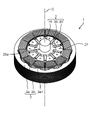
- FIG. 1 is a perspective view of an electric motor according to an embodiment of the present disclosure
- FIG. A perspective view of a rotor of the same electric motor.
- a plan view of the main part of the rotor of the motor A plan view of the main part in another embodiment of the rotor of the same electric motor
- each figure is a schematic diagram and is not necessarily strictly illustrated.
- symbol is attached
- FIG. 1 is a perspective view of an electric motor 1 according to an embodiment.
- the electric motor 1 includes a rotor 2 and a stator 3.
- Electric motor 1 in the present embodiment is an inner rotor type motor in which rotor 2 is arranged inside stator 3 . That is, the stator 3 is configured to surround the rotor 2 .
- the rotor 2 (rotor) is rotated by the magnetic force generated in the stator 3.
- the rotor 2 has a rotating shaft 10 and rotates about an axis C of the rotating shaft 10 as a rotation center.
- the rotor 2 generates a magnetic force that acts on the stator 3.
- the rotor 2 has a structure in which a plurality of N poles and S poles, which are main magnetic fluxes, are repeatedly present in the circumferential direction.
- the direction of the main magnetic flux generated by the rotor 2 is perpendicular to the direction of the axis C of the rotating shaft 10 (rotating shaft direction). That is, the direction of the main magnetic flux generated by the rotor 2 is the radial direction.
- the rotor 2 is arranged with the stator 3 through an air gap. Specifically, a minute air gap exists between the surface of the rotor 2 and the surface of the stator 3 .
- the rotor 2 is an embedded permanent magnet rotor (IPM rotor) in which permanent magnets are embedded in an iron core. Therefore, electric motor 1 in the present embodiment is an IPM motor.
- the stator 3 (stator) is arranged to face the rotor 2 via an air gap, and generates magnetic force acting on the rotor 2 .
- the stator 3 is arranged so as to surround the rotor core 20 of the rotor 2 .
- the stator 3 forms a magnetic circuit together with the rotor 2 .
- the stator 3 is configured so that N poles and S poles are alternately generated in the circumferential direction as the main magnetic flux on the air gap surface.
- the stator 3 has a stator core 3a (stator core) and winding coils 3b (stator coil).
- a plurality of teeth 3a1 projecting toward the rotor core 20 of the rotor 2 are provided on the stator core 3a.
- the plurality of teeth 3 a 1 are provided so as to protrude toward the axis C of the rotating shaft 10 .
- the plurality of teeth 3a1 are provided at regular intervals in the circumferential direction. Therefore, the multiple teeth 3a1 radially extend in a direction perpendicular to the axis C of the rotating shaft 10 (radial direction).
- the stator core 3a is composed of a plurality of steel plates laminated in the direction of the axis C of the rotating shaft 10, for example.
- Each of the plurality of steel plates is, for example, an electromagnetic steel plate punched into a predetermined shape.
- the stator core 3a is not limited to a laminate of a plurality of steel plates, and may be a bulk body made of a magnetic material.
- the winding coil 3b is wound around each of the plurality of teeth 3a1 of the stator core 3a. Specifically, the winding coil 3b is wound around each tooth 3a1 via an insulator.
- Each winding coil 3b is composed of unit coils of three phases, U-phase, V-phase and W-phase, which are electrically 120 degrees out of phase with each other. That is, the winding coil 3b wound around each tooth 3a1 is energized and driven by a three-phase alternating current that is energized in phase units of the U phase, the V phase, and the W phase. Thereby, the main magnetic flux of the stator 3 is generated in each tooth 3a1.
- the winding coil 3b is made of a metal material such as copper whose surface is coated with an insulating film, and has a circular or rectangular cross section.
- the electric motor 1 configured in this manner, when the winding coil 3b of the stator 3 is energized, a field current flows through the winding coil 3b to generate a magnetic field. Thereby, a magnetic flux is generated from the stator 3 toward the rotor 2 .
- the rotor 2 generates a magnetic flux directed toward the stator 3 . That is, the permanent magnets of rotor 2 generate a magnetic flux that passes through stator 3 .
- the magnetic force generated by the interaction between the magnetic flux generated by the stator 3 and the magnetic flux generated by the rotor 2 becomes torque for rotating the rotor 2 , and the rotor 2 rotates about the rotation axis 10 .
- FIG. 2 is a perspective view of the rotor 2 according to the embodiment.
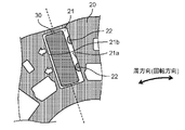
- FIG. 3 is a plan view of main parts of the rotor 2 according to the embodiment. 2 and 3, the rotating shaft 10 is omitted.
- the rotor 2 includes a rotating shaft 10, a rotor core 20, and a plurality of permanent magnets 30.
- the rotating shaft 10 is a long shaft that serves as the center when the rotor 2 rotates.
- the rotating shaft 10 is, for example, a metal rod and fixed to the center of the rotor 2 .
- the rotating shaft 10 is fixed to the rotor core 20 .
- rotating shaft 10 is fixed to rotor core 20 while penetrating through the center of rotor core 20 so as to protrude from both sides of rotor 2 .
- the rotating shaft 10 is fixed to the rotor core 20 by being press-fitted into a through hole 20a formed in the center of the rotor core 20 or by shrink fitting.
- a first portion of the rotating shaft 10 projecting to one side of the rotor 2 is supported by a first bearing, and a second portion of the rotating shaft 10 projecting to the other side of the rotor 2 is supported by a first bearing. It is supported by two bearings.
- a load driven by the electric motor 1 is attached to the first portion or the second portion of the rotating shaft 10 .
- the rotor core 20 (rotor core) is composed of, for example, a plurality of steel plates laminated in the direction of the axis C of the rotating shaft 10 .
- Each of the plurality of steel plates is, for example, an electromagnetic steel plate punched into a predetermined shape, and fixed to each other by caulking or the like.
- the rotor core 20 is not limited to a laminate of a plurality of steel plates, and may be a bulk body made of a magnetic material.
- the rotor core 20 is a core having a plurality of magnet placement holes 21.
- a plurality of magnet arrangement holes 21 are holes for magnet arrangement in which permanent magnets 30 are arranged.
- a permanent magnet 30 is inserted into the magnet placement hole 21 .
- the magnet arrangement hole 21 is a magnet insertion hole into which the permanent magnet 30 is inserted.
- One permanent magnet 30 is inserted into each magnet placement hole 21 .
- the rotor 2 is a ten-pole rotor having ten magnetic poles. Therefore, the rotor core 20 is provided with 10 magnet placement holes 21 and 10 permanent magnets 30 . Note that the present invention is not particularly limited to this, and can be applied to other numbers of magnetic poles.
- the magnet placement hole 21 is a through hole that penetrates the rotor core 20 along the direction of the axis C of the rotating shaft 10 . Therefore, the cross-sectional shape of the magnet arrangement hole 21 is the same in the direction of the axis C of the rotating shaft 10 in any cross section taken along a plane orthogonal to the rotating shaft 10 . In other words, all the steel plates forming the rotor core 20 are formed with the magnet arrangement holes 21 having the same shape. Note that the magnet arrangement hole 21 may not be a through hole as long as the permanent magnet 30 can be arranged.
- the plurality of magnet placement holes 21 are radially provided around the rotating shaft 10. As shown in FIGS. Also, the plurality of magnet placement holes 21 are provided at regular intervals along the circumferential direction of the rotor core 20 (the rotation direction of the rotating shaft 10). Each of the plurality of magnet arrangement holes 21 extends in the radial direction of the rotor core 20 (the direction orthogonal to the direction of the axis C of the rotating shaft 10) in plan view. That is, the magnet placement holes 21 are elongated in the radial direction of the rotor core 20, and the length in the radial direction is longer than the length in the rotational direction (circumferential direction).
- a plurality of elongated magnet placement holes 21 are formed in a spoke shape around the rotation shaft 10 . That is, the rotor 2 is a spoke-type IPM rotor, and the electric motor 1 is a spoke-type IPM motor.
- the plan view shape of each magnet placement hole 21 is substantially rectangular with the radial direction of the rotor core 20 as its longitudinal direction.
- the planar view shapes of the plurality of magnet placement holes 21 are the same.
- the magnet placement hole 21 may be elongated in the rotational direction (circumferential direction) of the rotor core 20, and the length in the rotational direction (circumferential direction) may be longer than the radial length.
- a permanent magnet 30 is inserted into each of the magnet arrangement holes 21 of the rotor 2 along the direction of the axis C of the rotating shaft 10 , and the permanent magnets 30 are inserted into each of the plurality of magnet arrangement holes 21 . placed.
- the permanent magnet 30 is inserted from above (above the paper) the axis C of the rotating shaft 10, but the permanent magnet 30 may be inserted from below (below the paper).
- the permanent magnet 30 is, for example, a sintered magnet.
- the plurality of permanent magnets 30 are arranged such that the magnetic pole direction is in the circumferential direction of the rotor core 20 (the rotation direction of the rotating shaft 10). That is, the permanent magnet 30 is magnetized so that the direction of the magnetic poles is the circumferential direction of the rotor core 20 .
- the magnetic poles of the two adjacent permanent magnets 30 have opposite directions of the S pole and the N pole.
- the planar view shape and size of the permanent magnet 30 are substantially the same as the planar view shape and size of the magnet placement hole 21 , and the permanent magnet 30 is fitted in the magnet placement hole 21 . Therefore, the planar view shape of the permanent magnet 30 is an elongated substantially rectangular shape.
- the permanent magnet 30 is a plate-like rectangular parallelepiped having a thickness in a direction perpendicular to the radial direction of the rotor core 20 . Note that the permanent magnet 30 in each magnet placement hole 21 may be divided into a plurality of pieces.
- each magnet placement hole 21 there is a gap (clearance) of a certain size between the outer surface of the permanent magnet 30 and the inner surface of the magnet placement hole 21 .
- An adhesive may be provided in this gap for adhesively fixing the permanent magnet 30 to the magnet arrangement hole 21 .
- the adhesive may not be provided in this gap.
- the permanent magnet 30 is composed of, for example, a Nd--Fe--B based sintered magnet or ferrite sintered magnet. Alternatively, it may be a bonded magnet formed of magnet powder such as Nd--Fe--B magnet powder or ferrite magnet powder, a resin material and a small amount of additives.
- the permanent magnets 30 may be magnetized after being placed in the magnet placement holes 21, or may be magnetized in advance before the permanent magnets 30 are inserted into the magnet placement holes 21. However, considering the workability of inserting the permanent magnet 30 into the magnet arrangement hole 21, it is better to magnetize the permanent magnet 30 after inserting it into the magnet arrangement hole 21. FIG.
- the permanent magnet 30 may be coated with a coating material made of resin to form a coating layer (not shown) to cover the periphery of the permanent magnet 30 .
- each magnet placement hole 21 is provided with two inner surfaces 21a and 21b facing each other in the circumferential direction (rotating direction of the rotating shaft 10) in plan view.
- Two protrusions 22 are provided on one inner surface 21a.
- the projecting portion 22 protrudes inwardly of the magnet placement hole 21 from the inner surface 21a of the magnet placement hole 21 in the circumferential direction of the magnet placement hole 21 in plan view.
- the projection 22 is formed only on one inner surface 21a (on the right side in the circumferential direction in FIG. 3) of the two inner surfaces 21a and 21b of each magnet arrangement hole 21 in the circumferential direction (rotating direction of the rotating shaft 10). .
- the permanent magnet 30 is inserted between the projecting portion 22 of the magnet placement hole 21 and the other inner surface 21b where the projecting portion 22 is not formed. At this time, the permanent magnet 30 is inevitably inserted on one side (left side in FIG. 3) of the circumferential central portion (broken line in FIG. 3) of the magnet placement hole 21 due to the existence of the protrusion 22 being an obstacle. .
- the permanent magnet 30 thus inserted is attracted (attracted) to the other inner surface 21b, since the other inner surface 21b, on which the protrusions 22 are not formed, is closer to the inner surface 21a, on which the protrusions 22 are formed. arrow direction), fixed. Since the permanent magnet 30 is always inserted to one side (the left side in FIG. 3) of the magnet arrangement hole 21 from the circumferential center (broken line in FIG. 3), the magnetic balance is lost and the permanent magnet 30 is always attracted to the other inner surface 21b. . Likewise, all the other permanent magnets 30 are automatically attracted to the left in a certain direction, for example, the circumferential direction inside the magnet arrangement hole 21 and fixed to the other inner surface 21b. Note that FIG. 3 shows the state at the time when the permanent magnet 30 is inserted into the magnet arrangement hole 21, after which it is attracted to the other inner surface 21b and sticks.
- the permanent magnet 30 can be fixed to the projection 22 of the magnet arrangement hole 21 and the projection 21b. It can be inserted with a distance from each other between the other inner surface 21b where 22 is not formed.
- the protrusions 22 may be formed integrally with the rotor core 20, for example. Moreover, it may be provided on the entire inner surface 21a of the magnet arrangement hole 21 in the axial direction, or may be provided on a part thereof. Moreover, in the present embodiment, the number of protrusions 22 is two, but the number may be other, for example, three or more.
- the projections 22 may be formed separately from the rotor core 20, and the projections 22 may be attached to the inner surface 21a of the magnet placement hole 21 with an adhesive or the like.
- the projecting portion 22 may be made of a non-magnetic material. With this configuration, the permanent magnets 30 can be fixed by the protrusions 22 without affecting the performance of the rotor 2 .
- FIG. 4 is a plan view of main parts of the rotor 2 showing another example of the present embodiment.
- FIG. 4 also shows the state when the permanent magnet 30 is inserted into the magnet arrangement hole 21, after which it is attracted to the other inner surface 21b and sticks.
- the curvature radii of the two corners 23a and 23b in contact with one inner surface 21a (right side in FIG. 4) of the four corners 23a to 23d when each magnet placement hole 21 is viewed from the axial direction are It is made larger than the radius of curvature of the two corners 23c and 23d in contact with the other inner surface 21b.
- the permanent magnet 30 inserted in this manner is attracted (in the direction of the arrow) and fixed to the other inner surface 21b where the diameters of the contacting corners 23c and 23d are smaller. Since the permanent magnet 30 is always inserted on one side (left side in FIG. 4) of the magnet arrangement hole 21 from the circumferential central portion (broken line in FIG. 4), it is always attracted to the other inner surface 21b side. Likewise, all the other permanent magnets 30 are automatically attracted leftward in a certain direction, for example, the circumferential direction, and fixed inside the magnet placement hole 21 .
- each magnet arrangement hole 21 is arranged on one side surface (left side in the figure) in each magnet arrangement hole 21 in the circumferential direction. securely fixed. 5 schematically shows the relationship between each magnet arrangement hole 21 and the permanent magnet 30, and each permanent magnet 30 is attracted in the direction of the arrow in the figure.
- the permanent magnet 30 can be inserted into the magnet arrangement hole 21 with a distance between the protrusion 22 and the other inner surface 21b on which the protrusion 22 is not formed. That is, the permanent magnet 30 can be inserted into the magnet arrangement hole 21 without contacting the inner surface of the magnet arrangement hole 21 and the protrusion 22 . Therefore, it is not necessary to press-fit the permanent magnet 30 into the magnet placement hole 21 . If it is press-fitted, problems such as damage to the coating layer covering the permanent magnet 30 and deformation of the rotor core 20 may occur. However, in the present embodiment, even if the permanent magnet 30 and the protrusion 22 are separated from each other, the magnetic balance may be disturbed, and there is no need to press fit them. Therefore, such a problem can be prevented.
- the rotor and the electric motor according to the present disclosure can be widely used in electric motors and the like used in various devices including household electrical equipment and industrial equipment.
Abstract
L'invention concerne un rotor et un moteur électrique qui sont aptes à réduire une ondulation de couple. Ce rotor comprend : un noyau de rotor (20) comportant une pluralité de trous de placement d'aimant (21) ; une pluralité d'aimants permanents (30) disposés respectivement dans la pluralité de trous de placement d'aimant (21) ; et un arbre rotatif fixé au noyau de rotor (20). La pluralité de trous de placement d'aimant (21) est disposée radialement autour de l'arbre rotatif. Parmi les surfaces internes (21a), (21b) de chaque trou de la pluralité de trous de placement d'aimant (21) dans la direction de rotation, la surface interne (21a) est pourvue d'une partie en saillie (22).
Priority Applications (1)
| Application Number | Priority Date | Filing Date | Title |
|---|---|---|---|
| JP2023514364A JPWO2022219923A1 (fr) | 2021-04-13 | 2022-02-21 |
Applications Claiming Priority (2)
| Application Number | Priority Date | Filing Date | Title |
|---|---|---|---|
| JP2021067435 | 2021-04-13 | ||
| JP2021-067435 | 2021-04-13 |
Publications (1)
| Publication Number | Publication Date |
|---|---|
| WO2022219923A1 true WO2022219923A1 (fr) | 2022-10-20 |
Family
ID=83639617
Family Applications (1)
| Application Number | Title | Priority Date | Filing Date |
|---|---|---|---|
| PCT/JP2022/006830 WO2022219923A1 (fr) | 2021-04-13 | 2022-02-21 | Rotor et moteur électrique |
Country Status (2)
| Country | Link |
|---|---|
| JP (1) | JPWO2022219923A1 (fr) |
| WO (1) | WO2022219923A1 (fr) |
Citations (7)
| Publication number | Priority date | Publication date | Assignee | Title |
|---|---|---|---|---|
| JP2001339919A (ja) * | 2000-05-25 | 2001-12-07 | Toshiba Corp | 永久磁石式リラクタンス型回転電機 |
| JP2002034185A (ja) * | 2000-07-17 | 2002-01-31 | Toshiba Corp | 永久磁石式リラクタンス型回転電機 |
| JP2006238584A (ja) * | 2005-02-24 | 2006-09-07 | Toyota Motor Corp | ロータおよびその製造方法 |
| JP2007104888A (ja) * | 2005-09-07 | 2007-04-19 | Toshiba Corp | 回転電機 |
| JP2015076956A (ja) * | 2013-10-08 | 2015-04-20 | 株式会社ジェイテクト | ロータコア及び磁石埋込型ロータ |
| JP2017184571A (ja) * | 2016-03-31 | 2017-10-05 | 株式会社豊田自動織機 | 永久磁石式回転電機 |
| JP2021097527A (ja) * | 2019-12-18 | 2021-06-24 | 株式会社ミツバ | ブラシレスモータ |
-
2022
- 2022-02-21 JP JP2023514364A patent/JPWO2022219923A1/ja active Pending
- 2022-02-21 WO PCT/JP2022/006830 patent/WO2022219923A1/fr active Application Filing
Patent Citations (7)
| Publication number | Priority date | Publication date | Assignee | Title |
|---|---|---|---|---|
| JP2001339919A (ja) * | 2000-05-25 | 2001-12-07 | Toshiba Corp | 永久磁石式リラクタンス型回転電機 |
| JP2002034185A (ja) * | 2000-07-17 | 2002-01-31 | Toshiba Corp | 永久磁石式リラクタンス型回転電機 |
| JP2006238584A (ja) * | 2005-02-24 | 2006-09-07 | Toyota Motor Corp | ロータおよびその製造方法 |
| JP2007104888A (ja) * | 2005-09-07 | 2007-04-19 | Toshiba Corp | 回転電機 |
| JP2015076956A (ja) * | 2013-10-08 | 2015-04-20 | 株式会社ジェイテクト | ロータコア及び磁石埋込型ロータ |
| JP2017184571A (ja) * | 2016-03-31 | 2017-10-05 | 株式会社豊田自動織機 | 永久磁石式回転電機 |
| JP2021097527A (ja) * | 2019-12-18 | 2021-06-24 | 株式会社ミツバ | ブラシレスモータ |
Also Published As
| Publication number | Publication date |
|---|---|
| JPWO2022219923A1 (fr) | 2022-10-20 |
Similar Documents
| Publication | Publication Date | Title |
|---|---|---|
| JP5268711B2 (ja) | 電動機及び圧縮機及び空気調和機及び電気掃除機 | |
| CN109075681B (zh) | 电动机及空气调节机 | |
| WO2018037449A1 (fr) | Rotor à pôles conséquents, moteur électrique et climatiseur | |
| JP6048191B2 (ja) | マルチギャップ型回転電機 | |
| US9356479B2 (en) | Hybrid excitation rotating electrical machine | |
| US20230253838A1 (en) | Electric motor | |
| WO2018117195A1 (fr) | Machine électrique tournante | |
| JP6545393B2 (ja) | コンシクエントポール型の回転子、電動機および空気調和機 | |
| JPWO2022019074A5 (fr) | ||
| JP2019126102A (ja) | 回転子および回転電機 | |
| JP2013123327A (ja) | 回転電機 | |
| JP2005151785A (ja) | リング状の電機子コイルを有する同期発電機 | |
| WO2017212575A1 (fr) | Moteur à aimants permanents | |
| WO2022219923A1 (fr) | Rotor et moteur électrique | |
| WO2022255038A1 (fr) | Rotor et moteur électrique | |
| WO2022219942A1 (fr) | Rotor et moteur électrique | |
| WO2023276513A1 (fr) | Rotor, procédé associé de fabrication et moteur électrique | |
| WO2023276514A1 (fr) | Rotor, son procédé de fabrication et moteur électrique | |
| WO2023276512A1 (fr) | Rotor et son procédé de fabrication, et moteur électrique | |
| JPWO2022219923A5 (fr) | ||
| WO2013111335A1 (fr) | Machine électrique tournante | |
| KR20210120100A (ko) | 회전 전기 기계 | |
| JPWO2022219942A5 (fr) | ||
| WO2021210249A1 (fr) | Rotor et moteur électrique | |
| WO2017175461A1 (fr) | Machine électrique tournante à entrefer axial |
Legal Events
| Date | Code | Title | Description |
|---|---|---|---|
| 121 | Ep: the epo has been informed by wipo that ep was designated in this application |
Ref document number: 22787851 Country of ref document: EP Kind code of ref document: A1 |
|
| WWE | Wipo information: entry into national phase |
Ref document number: 2023514364 Country of ref document: JP |
|
| NENP | Non-entry into the national phase |
Ref country code: DE |
|
| 122 | Ep: pct application non-entry in european phase |
Ref document number: 22787851 Country of ref document: EP Kind code of ref document: A1 |