WO2022219893A1 - Hplcを有する自動分析装置及びその自動分析装置の制御方法 - Google Patents
Hplcを有する自動分析装置及びその自動分析装置の制御方法 Download PDFInfo
- Publication number
- WO2022219893A1 WO2022219893A1 PCT/JP2022/004376 JP2022004376W WO2022219893A1 WO 2022219893 A1 WO2022219893 A1 WO 2022219893A1 JP 2022004376 W JP2022004376 W JP 2022004376W WO 2022219893 A1 WO2022219893 A1 WO 2022219893A1
- Authority
- WO
- WIPO (PCT)
- Prior art keywords
- pressure
- change amount
- liquid
- specified
- sample introduction
- Prior art date
- Legal status (The legal status is an assumption and is not a legal conclusion. Google has not performed a legal analysis and makes no representation as to the accuracy of the status listed.)
- Ceased
Links
Images


Classifications
-
- G—PHYSICS
- G01—MEASURING; TESTING
- G01N—INVESTIGATING OR ANALYSING MATERIALS BY DETERMINING THEIR CHEMICAL OR PHYSICAL PROPERTIES
- G01N30/00—Investigating or analysing materials by separation into components using adsorption, absorption or similar phenomena or using ion-exchange, e.g. chromatography or field flow fractionation
- G01N30/02—Column chromatography
- G01N30/26—Conditioning of the fluid carrier; Flow patterns
- G01N30/28—Control of physical parameters of the fluid carrier
- G01N30/32—Control of physical parameters of the fluid carrier of pressure or speed
-
- G—PHYSICS
- G01—MEASURING; TESTING
- G01N—INVESTIGATING OR ANALYSING MATERIALS BY DETERMINING THEIR CHEMICAL OR PHYSICAL PROPERTIES
- G01N30/00—Investigating or analysing materials by separation into components using adsorption, absorption or similar phenomena or using ion-exchange, e.g. chromatography or field flow fractionation
- G01N30/02—Column chromatography
- G01N30/26—Conditioning of the fluid carrier; Flow patterns
- G01N30/38—Flow patterns
- G01N30/46—Flow patterns using more than one column
- G01N30/468—Flow patterns using more than one column involving switching between different column configurations
-
- G—PHYSICS
- G01—MEASURING; TESTING
- G01N—INVESTIGATING OR ANALYSING MATERIALS BY DETERMINING THEIR CHEMICAL OR PHYSICAL PROPERTIES
- G01N30/00—Investigating or analysing materials by separation into components using adsorption, absorption or similar phenomena or using ion-exchange, e.g. chromatography or field flow fractionation
- G01N30/02—Column chromatography
- G01N30/88—Integrated analysis systems specially adapted therefor, not covered by a single one of the groups G01N30/04 - G01N30/86
-
- G—PHYSICS
- G01—MEASURING; TESTING
- G01N—INVESTIGATING OR ANALYSING MATERIALS BY DETERMINING THEIR CHEMICAL OR PHYSICAL PROPERTIES
- G01N30/00—Investigating or analysing materials by separation into components using adsorption, absorption or similar phenomena or using ion-exchange, e.g. chromatography or field flow fractionation
- G01N30/02—Column chromatography
- G01N2030/022—Column chromatography characterised by the kind of separation mechanism
- G01N2030/027—Liquid chromatography
-
- G—PHYSICS
- G01—MEASURING; TESTING
- G01N—INVESTIGATING OR ANALYSING MATERIALS BY DETERMINING THEIR CHEMICAL OR PHYSICAL PROPERTIES
- G01N30/00—Investigating or analysing materials by separation into components using adsorption, absorption or similar phenomena or using ion-exchange, e.g. chromatography or field flow fractionation
- G01N30/02—Column chromatography
- G01N30/26—Conditioning of the fluid carrier; Flow patterns
- G01N30/28—Control of physical parameters of the fluid carrier
- G01N30/32—Control of physical parameters of the fluid carrier of pressure or speed
- G01N2030/324—Control of physical parameters of the fluid carrier of pressure or speed speed, flow rate
-
- G—PHYSICS
- G01—MEASURING; TESTING
- G01N—INVESTIGATING OR ANALYSING MATERIALS BY DETERMINING THEIR CHEMICAL OR PHYSICAL PROPERTIES
- G01N30/00—Investigating or analysing materials by separation into components using adsorption, absorption or similar phenomena or using ion-exchange, e.g. chromatography or field flow fractionation
- G01N30/02—Column chromatography
- G01N30/26—Conditioning of the fluid carrier; Flow patterns
- G01N30/28—Control of physical parameters of the fluid carrier
- G01N30/32—Control of physical parameters of the fluid carrier of pressure or speed
- G01N2030/328—Control of physical parameters of the fluid carrier of pressure or speed valves, e.g. check valves of pumps
-
- G—PHYSICS
- G01—MEASURING; TESTING
- G01N—INVESTIGATING OR ANALYSING MATERIALS BY DETERMINING THEIR CHEMICAL OR PHYSICAL PROPERTIES
- G01N30/00—Investigating or analysing materials by separation into components using adsorption, absorption or similar phenomena or using ion-exchange, e.g. chromatography or field flow fractionation
- G01N30/02—Column chromatography
- G01N30/26—Conditioning of the fluid carrier; Flow patterns
- G01N30/38—Flow patterns
- G01N2030/382—Flow patterns flow switching in a single column
- G01N2030/385—Flow patterns flow switching in a single column by switching valves
-
- G—PHYSICS
- G01—MEASURING; TESTING
- G01N—INVESTIGATING OR ANALYSING MATERIALS BY DETERMINING THEIR CHEMICAL OR PHYSICAL PROPERTIES
- G01N30/00—Investigating or analysing materials by separation into components using adsorption, absorption or similar phenomena or using ion-exchange, e.g. chromatography or field flow fractionation
- G01N30/02—Column chromatography
- G01N30/88—Integrated analysis systems specially adapted therefor, not covered by a single one of the groups G01N30/04 - G01N30/86
- G01N2030/8804—Integrated analysis systems specially adapted therefor, not covered by a single one of the groups G01N30/04 - G01N30/86 automated systems
Definitions
- the present invention relates to an automatic analyzer having HPLC and a control method for the automatic analyzer.
- HPLC high-performance liquid chromatograph
- HPLC is a chromatogram that uses a liquid as a mobile phase sent to a separation column that separates samples.
- the particle size of the packing material is made small, and the analysis is performed using the liquid compressed at high pressure by the liquid feeding device.
- a component detection method using an automatic analyzer having HPLC uses the difference in affinity between a stationary phase and a mobile phase packed in a separation column to separate a liquid sample into a plurality of components, each separated component is This is a method of detection using a detector.
- HPLC measurement data is displayed as a peak that shows the relationship between sample retention time and detector signal intensity.
- the retention time is the peak top time, and shows almost the same value for each sample component if the analysis conditions are the same. Retention times are therefore used as information for identifying separated components.
- the liquid feed pressure or the detection time of the component to be analyzed may fluctuate in one direction, or the user may decide that the equilibration was not sufficient and re-measure.
- liquid transfer in HPLC analysis is performed at high pressure.
- Patent Document 1 describes a technique that monitors the upper and lower limits of the normal pressure of the pump, for example, if the pressure exceeds the upper limit, issues an alarm that the pressure is abnormal and allows the user to check. If the pressure is abnormal, it is necessary to immediately stop the liquid transfer, prevent damage to the liquid transfer pump, and check for clogging of the flow path.
- An object of the present invention is to have an HPLC capable of automatically judging the completion of column equilibration, which is performed as a preparatory operation for measurement, and at the same time specifying the location of the error when an error occurs during the equilibration process.
- An object of the present invention is to provide an automatic analyzer and a control method for the automatic analyzer.
- the present invention is configured as follows.
- a liquid-feeding unit having a liquid-feeding device and a liquid-feeding channel connected to the liquid-feeding device, a liquid-feeding unit for feeding a mobile phase, and a sample introduction for introducing a sample into the mobile phase fed from the liquid-feeding unit a separation column into which a sample is introduced from the sample introduction unit and separated into a plurality of components; a detector that detects the components separated by the separation column; a liquid feed unit; a sample introduction unit;
- the liquid-transmitting device has a liquid-transmitting device and a liquid-transmitting channel connected to the liquid-transmitting device.
- a control method for an automatic analyzer having HPLC comprising a separation column for separating components, a detector for detecting the separated components, and a control unit for controlling the liquid feeding unit, the sample introduction unit and the detector, Detect the pressure in the liquid transfer channel, and based on the detected pressure, the pressure increase rate immediately after the liquid transfer unit starts to transfer the mobile phase, and the compression after the liquid transfer unit continues to transfer the mobile phase for a certain period of time.
- the pressure change and pressure average are calculated to determine the completion of equilibration of the separation column.
- the present invention has an HPLC that makes it possible to automatically determine the completion of column equilibration, which is performed as a preparatory operation for measurement, and at the same time, if an error occurs in the equilibration process, to identify the location of the error.
- An automatic analyzer and a control method for the automatic analyzer can be provided.
- FIG. 1 is a schematic configuration diagram of an automatic analyzer having HPLC according to Example 1.
- FIG. 4 is a flow chart for determining completion of column equilibration in Example 1.
- FIG. 3 is a graph when the pressure increase rate is within a specified value in FIG. 2.
- FIG. 3 is a graph when the pressure increase rate is out of the specified value in FIG. 2.
- FIG. 4 is a flow chart for implementing a process of specifying a leak location in Example 1.
- FIG. 1 is a schematic configuration diagram of an automatic analyzer having HPLC according to Example 2.
- FIG. 10 is a flow chart for implementing a process of specifying a leak location in Example 2.
- FIG. FIG. 11 is a schematic diagram of a display unit in Example 2;
- the automatic analyzer After the power is turned on, the automatic analyzer is started up, the communication between the analysis unit and the control unit is confirmed, and the status of each sensor and consumables is checked. The user or service person selects maintenance items. "pre-measurement preparation process” to be carried out, calibration measurement, QC (Quality Control) measurement used to maintain the quality of analysis and sample measurement "main measurement process", waiting after the main measurement process "standby process ”, a “post-measurement preparation step” for making preparations for turning off the automatic analyzer, and a “shutdown step” for turning off the automatic analyzer.
- pre-measurement preparation process to be carried out
- calibration measurement QC (Quality Control) measurement used to maintain the quality of analysis and sample measurement "main measurement process”, waiting after the main measurement process "standby process ”, a “post-measurement preparation step” for making preparations for turning off the automatic analyzer, and a “shutdown step” for turning off the automatic analyzer.
- QC Quality Control
- the present invention is implemented in the "pre-measurement preparation process" of the workflow shown above.
- FIG. 1 is a schematic configuration diagram of an automatic analyzer 100 having HPLC according to Example 1 of the present invention.
- an automatic analyzer 100 having HPLC includes a mobile phase tank 101, a liquid feeding unit 102 (liquid feeding section), a sample introduction unit 103 (sample introduction section), a column temperature adjustment unit (column temperature adjustment section ) 104 , a detector 105 , an integrated control section 114 , an operation section 118 and a display section 119 .
- the liquid sending unit 102 (liquid sending section) and the sample introduction unit 103 (sample introduction section) are connected via an analysis channel C1 (first analysis channel), and the mobile phase is introduced into the sample introduction unit 103. .
- the liquid sending unit 102 includes, for example, a liquid sending device 106, a pressure detector 107, a purge valve 108, a liquid sending channel C0, an analysis channel C1 (first analysis channel), and a waste liquid channel C2.
- a liquid sending device 106 has a function of sucking the mobile phase used for transporting or separating the sample from the mobile phase tank 101, compressing it under high pressure, and discharging it.
- this liquid transfer unit 102 can be configured as an HPLC system capable of transferring one or more mobile phases from one liquid transfer device 106 .
- the pressure detector 107 is a sensor device (pressure sensor) that detects (monitors) the pressure in the liquid-feeding channel C0 that feeds the mobile phase of the liquid-feeding unit 102 and the pipe up to the detector 105 .
- the purge valve 108 is connected downstream of the liquid delivery device 106 and has a function of selectively connecting the liquid delivery channel C0 to the analysis channel C1 connected to the sample introduction unit 103 or the waste liquid channel C2.
- the purge valve 108 is configured so as to form a tightly plugged state in which it is not connected to either the analysis channel C1 or the waste liquid channel C2 when performing a pressure resistance test.
- the sample introduction unit 103 is roughly composed of a sample introduction valve 109 , a sample metering pump 110 and a needle 111 .
- the sample introduction valve 109 is connected to the aforementioned analysis channel C1 and has a switching function for introducing the mobile phase into the downstream analysis channel C3 (second analysis channel).
- the sample introduction valve 109 has a sample introduction port 112 for introducing the sample.
- the sample metering pump 110 has a function of discharging the sample to be analyzed into the sample introduction port 112 through the needle 111 .
- the sample introduced from the sample metering pump 110 to the sample introduction valve 109 is mixed with the mobile phase and discharged to the analysis channel C3.
- the sample introduction valve 109 is also connected to the waste liquid channel C4.
- the column temperature adjustment unit 104 can accommodate a separation column 113, and the separation column 113 is connected to the sample introduction unit 103 via the analysis channel C3, and a plurality of samples introduced by the mobile phase from the sample introduction unit 103 are collected. components.
- the detector 105 is connected downstream of the column temperature adjustment unit 104 via the analysis channel C5 (third analysis channel) and has a function of detecting each component of the sample separated in the separation column 113 .
- the integrated control unit 114 is a control unit for controlling the liquid feeding unit 102, the sample introduction unit 103, the column temperature adjustment unit 104, and the detector 105 to obtain HPLC data.
- the integrated control unit 114 includes an analysis condition setting unit 115 that sets analysis conditions for controlling the liquid feeding unit 102, the sample introduction unit 103, and the column temperature adjustment unit 104 described above, and the analysis output by the detector 105. It has a data processing unit 116 for analyzing the results, and an analysis control unit 117 for outputting the start timing of each analysis to each unit 102-104.
- the integrated control unit 114 determines the pressure increase rate immediately after the liquid transfer unit (liquid transfer unit) 102 starts to transfer the mobile phase, and the compression pressure change after the liquid transfer is continued for a certain period of time. Volume and pressure averages are calculated to automatically determine the completion of equilibration of the separation column 113 .
- the operation unit 118 includes input devices such as a keyboard, numeric keypad, mouse, etc., and is a device for inputting various instructions from the user regarding control in the integrated control unit 114 .
- the display unit 119 is a device for displaying analysis conditions and analysis results, and can be composed of, for example, a liquid crystal display or an organic EL display.
- the integrated control unit calculates the rate of increase in pressure detected by the pressure detector 107, and in step S202, the pressure rate of increase is equal to the specified rate of increase. Determines whether or not it is within the value. If the pressure rise rate is greater than the specified rise rate value, the process proceeds to step S206, alarm 1 (separation column or piping replacement alarm) is displayed on the display unit 119, and the liquid transfer is immediately stopped to allow the automatic analyzer to Minimize damage to 100.
- alarm 1 separation column or piping replacement alarm
- Fig. 3A is a graph showing pressure changes during normal liquid feeding
- Fig. 3B is a graph showing pressure changes during abnormal conditions.
- P/T pressure and time
- step S202 if the rate of increase in pressure is within the specified value, liquid feeding is continued, the process proceeds to step 203, and liquid feeding is continued until the pressure change amount is within the specified pressure change amount value.
- step S203 it is determined whether or not the pressure change amount is within the specified pressure change amount value. If it is less than N times, the process returns to step S203.
- step S207 if the number of retries is N, it is determined that the pressure change amount is not within the specified pressure change amount value. ) is displayed on the display unit 119 .
- the time to continue liquid transfer varies depending on the column capacity and solvent used, and it is possible for the user to set the time to continue liquid transfer.
- the liquid transfer can be continued (retry) until the set time elapses again, and the user sets the number of retries N. can do.
- step 203 when the pressure change amount becomes within the specified value within the set time, the process proceeds to step S204 to determine whether or not the pressure average is within the specified pressure range. For example, if the separation column 113 is normally used at 60 MPa and the user sets 55 MPa to 65 MPa as the specified value, it is determined that the equilibration is complete if the pressure is within the specified pressure range.
- step 205 proceed to complete the equilibration.
- step S204 if the pressure average is not within the specified pressure range, proceed to step S208 to determine whether it is higher than the specified pressure range.
- step S208 if the pressure average is higher than the specified pressure upper limit (for example, 65 MPa), the process proceeds to step S209, alarm 3 (separation column or piping replacement alarm) is displayed on the display unit 119, and the column and piping are displayed to the user. encourage the exchange of
- step S208 if the pressure average is lower than the specified pressure lower limit (for example, 55 MPa), a leak from a pipe joint is suspected, and the flow proceeds to step S211, and according to the workflow shown in FIG. It is determined whether a leak has occurred (whether it has occurred).
- the specified pressure lower limit for example, 55 MPa
- FIG. 4 showing the leak confirmation flow shown in step S211 shown in FIG.
- step S401 in Fig. 4 it is determined whether or not the amount of change in compression pressure k in the compression section of the liquid transfer device 106 is equal to or less than a certain value (specified amount of change in compression pressure). If the compression pressure change amount k is equal to or less than a certain value, the process proceeds to step S405, it is determined that there is a portion where leakage occurs from the cylinder in the liquid transfer device 106, and alarm 4 (from the cylinder in the liquid transfer device 106 An alarm indicating that there is a leak in the supplied liquid) is displayed on the display unit 119 .
- a certain value specified amount of change in compression pressure
- the user needs to replace expendable parts such as the plunger seal inside the cylinder of the liquid transfer device 106 .
- step S401 if the compression pressure change amount k is not less than a certain value (specified compression pressure change amount) and there is no abnormality, the process proceeds to step S402, the purge valve 108 is sealed and pressure resistance is checked to determine whether it is normal or not. judge. As described above, the purge valve 108 can be sealed by moving it to a position where it is not connected to any channel.
- the purge valve 108 may be brought into a sealed state by once removing the piping and installing a sealed plug, or by preparing a port with a sealed plug attached to the purge valve 108 .
- step S402 if the pressure resistance check result of the purge valve 108 is abnormal, the process proceeds to step S406 to display alarm 5 (an alarm that there is a leak in the liquid sent to the upstream side of the purge valve 108) on the display unit 119. It is determined that there is a portion where a leak has occurred in the flow path piping, and the user is urged to replace the part or the like.
- step S402 if the pressure resistance check result of the purge valve 108 is normal, the process proceeds to step S403, and the pressure resistance check of the sample introduction valve (injection valve) 109 is subsequently performed.
- step S403 if the pressure resistance check result of the sample introduction valve 109 is abnormal, the process proceeds to step S407 and alarm 6 (an alarm indicating that a liquid feed leak has occurred between the sample introduction valve 109 and the purge valve 108). is displayed on the display unit 119, it is determined that there is a leak in the flow path piping between the sample introduction valve 109 and the purge valve 108, and the user is urged to replace the valve.
- step S403 if the pressure resistance check result of the sample introduction valve 109 is normal, it is determined that there is a portion where the liquid is leaking downstream of the sample introduction valve 109, and the process proceeds to step S404, where alarm 7 (sample introduction valve 109 downstream) is displayed on the display unit 119 to urge the user to replace it.
- step S208 in FIG. 2 if the pressure is clearly low, a leak that can be seen visually can be confirmed, but if the pressure is slightly low, a slight slow leak that cannot be seen may occur. Running the workflow shown in is useful for discovering leaks.
- the completion of column equilibration which is performed as a preparatory operation for measurement, is automatically determined. to display alarms 1 to 7 on the display unit 119.
- an automatic analyzer having HPLC and a control method for the automatic analyzer which makes it possible to automatically determine the completion of column equilibration and, at the same time, identify the location of the error when an error occurs in the equilibration process. can be provided.
- Example 2 Next, Example 2 of the present invention will be described.
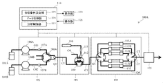
- FIG. 5 is a schematic configuration diagram of an automatic analyzer 100A having an HPLC according to Example 2.
- the same reference numerals are given to the same components as those of the first embodiment, and duplicate descriptions will be omitted below.
- the liquid sending unit 102 includes two liquid sending devices 106A (first liquid sending device) and 106B (second liquid sending device). , and the two liquid delivery devices 106A and 106B are connected to different mobile phase tanks 101A (first mobile phase tank) and 101B (second mobile phase tank), respectively.
- Pressure detectors 107A and 107B are connected to the liquid-sending channels C01 and C02 connected to the ejection ports of the liquid-sending devices 106A and 106B, respectively. Further, a purge valve 108A for selectively switching between the analysis channel and the waste liquid channel is provided downstream of the two liquid transfer devices 106A and 106B. The mobile phase discharged from the purge valve 108A is introduced into the sample introduction unit 103 via the confluence Q1.
- the configuration of the sample introduction unit 103 is the same as that of the first embodiment.
- the junction Q1 is installed downstream of the purge valve 108A, but it is also possible to install the junction Q1 upstream of the purge valve 108A.
- a common pressure detector for the liquid delivery devices 106A and 106B can be arranged downstream of the junction Q1 and upstream of the purge valve 108A.
- the column temperature adjustment unit 104 is configured to accommodate a plurality of separation columns 113A, 113B, 113C, 113D and 113E arranged in parallel.
- the plurality of separation columns 113A-113E contain packing materials of different properties.
- column temperature conditioning unit 104 includes a bypass flow path 120 that allows the mobile phase to enter detector 105 without passing through separation columns 113A-113E.
- This bypass channel 120 is arranged in parallel with the plurality of separation columns 113A-113E in the column temperature adjustment unit 104.
- the column temperature adjustment unit 104 includes a column switching valve (first column switching valve) 121 and a column switching valve 122 (second column switching valves) are provided upstream and downstream of the separation columns 113A-113E.
- the column switching valves 121 and 122 are connected to the separation columns 113A to 113E and the bypass channel 120, the plurality of first pipe connection parts, the analysis channel (analysis channel C3, the column switching valve 122 and the detector 105, and and a movable channel for selectively connecting the first and second pipe connections.
- the plurality of separation columns 113A-113E, or the bypass flow path 120 can be connected to the analysis channel.
- the column switching valves (column selector valves) 121 and 122 are used not only to connect any of the plurality of separation columns 113A to 113E or the bypass channel 120 to the analysis channel C3 or C5, but also to separate the separation columns. 113A to 113E or the bypass channel 120 can be selectively connected (sealed state).
- step S403 in FIG. 6 Since the column selector valves 121 and 122 are configured to be sealed, as shown in the flow chart of FIG. 6, in step S403 in FIG. In this case, by executing pressure resistance check process steps S601 to S605 of the column switching valves 121 and 122, it is possible to determine where the leak occurs.
- the steps preceding step S403 in FIG. 6 are the same as those in FIG. 4, and therefore are omitted.
- step S601 of FIG. 6 a pressure resistance check is performed with the column selector valve 121 in a sealed state. An alarm indicating that there is a leak with the valve 121) is displayed on the display unit 119 to prompt the user to replace the valve.
- step S601 If the pressure resistance check result of the column switching valve 121 is normal in step S601, the process proceeds to step S602, and the pressure resistance check of the column switching valve (column selector valve) 122 is performed.
- the channel between the column switching valves 121 and 122 is connected to the bypass channel 120 for implementation.
- step S602 if the result of the pressure resistance check of the column switching valve 122 is abnormal, alarm 6-2 (leak in the flow path piping between the column switching valve (column selector valve) 121 and the column switching valve (column selector valve) 122 ) is displayed on the display unit 119 to urge the user to replace the battery.
- step S602 if the pressure resistance check of the column switching valve 122 is normal, an alarm 6-3 (an alarm indicating that a leak has occurred in the flow path piping downstream of the column switching valve 122) is displayed on the display unit 119. , to prompt the user to replace.
- an alarm 6-3 an alarm indicating that a leak has occurred in the flow path piping downstream of the column switching valve 122
- the display unit 119 shown in FIG. 5 is shown in detail in FIG.
- the display unit 119 displays measurement results, error information, the number of times each replacement part has been used, the replacement history of each replacement part, the determination result of this preparatory operation, and information on changes in pressure values over time (trend). It can be displayed together with the schematic diagram of the device configuration as shown in FIG. 5, and the degree of danger predicted from the trend can be shown on the schematic diagram.
- Example 2 similarly to Example 1, the completion of column equilibration, which is performed as a preparatory operation for measurement, is automatically determined. It is possible to provide an automatic analyzer having HPLC and a method for controlling the automatic analyzer.
- Example 2 when the column temperature adjustment unit 104 is configured to accommodate a plurality of separation columns 113A, 113B, 113C, 113D, and 113E, where in the column temperature adjustment unit 104 is the leak occurred? It is possible to provide an automated analyzer with HPLC that can determine what is happening and a control method for the automated analyzer.
- the present invention is not limited to the above embodiments, and includes various modifications.
- the above embodiments have been described in detail in order to explain the present invention in an easy-to-understand manner, and are not necessarily limited to those having all the configurations described. That is, various changes, additions, and omissions can be added to part of the configuration of the embodiment.
- detection of defects in the automatic analyzer of the present invention does not have to be performed by checking the pressure sensor value during preparatory operation, and detection of defective locations may be performed.
- detection of the defective part may be performed.
Landscapes
- Physics & Mathematics (AREA)
- Health & Medical Sciences (AREA)
- Life Sciences & Earth Sciences (AREA)
- Chemical & Material Sciences (AREA)
- Analytical Chemistry (AREA)
- Biochemistry (AREA)
- General Health & Medical Sciences (AREA)
- General Physics & Mathematics (AREA)
- Immunology (AREA)
- Pathology (AREA)
- Automatic Analysis And Handling Materials Therefor (AREA)
Priority Applications (4)
| Application Number | Priority Date | Filing Date | Title |
|---|---|---|---|
| US18/554,237 US20240192180A1 (en) | 2021-04-14 | 2022-02-04 | Automatic analyzer including hplc and control method for the same |
| EP22787821.2A EP4325218A4 (en) | 2021-04-14 | 2022-02-04 | AUTOMATIC ANALYSIS DEVICE WITH HPLC AND METHOD FOR CONTROLLING THE AUTOMATIC ANALYSIS DEVICE |
| CN202280025659.5A CN117136301A (zh) | 2021-04-14 | 2022-02-04 | 具有hplc的自动分析装置以及该自动分析装置的控制方法 |
| JP2023514349A JP7556135B2 (ja) | 2021-04-14 | 2022-02-04 | Hplcを有する自動分析装置及びその自動分析装置の制御方法 |
Applications Claiming Priority (2)
| Application Number | Priority Date | Filing Date | Title |
|---|---|---|---|
| JP2021-068408 | 2021-04-14 | ||
| JP2021068408 | 2021-04-14 |
Publications (1)
| Publication Number | Publication Date |
|---|---|
| WO2022219893A1 true WO2022219893A1 (ja) | 2022-10-20 |
Family
ID=83639562
Family Applications (1)
| Application Number | Title | Priority Date | Filing Date |
|---|---|---|---|
| PCT/JP2022/004376 Ceased WO2022219893A1 (ja) | 2021-04-14 | 2022-02-04 | Hplcを有する自動分析装置及びその自動分析装置の制御方法 |
Country Status (5)
| Country | Link |
|---|---|
| US (1) | US20240192180A1 (https=) |
| EP (1) | EP4325218A4 (https=) |
| JP (1) | JP7556135B2 (https=) |
| CN (1) | CN117136301A (https=) |
| WO (1) | WO2022219893A1 (https=) |
Cited By (1)
| Publication number | Priority date | Publication date | Assignee | Title |
|---|---|---|---|---|
| WO2026070108A1 (ja) * | 2024-09-27 | 2026-04-02 | 株式会社日立ハイテク | 自動分析装置 |
Citations (9)
| Publication number | Priority date | Publication date | Assignee | Title |
|---|---|---|---|---|
| JPS57110959A (en) * | 1980-12-27 | 1982-07-10 | Shimadzu Corp | Automatic indicating device for specimen-introducing time |
| JPH01142461A (ja) * | 1987-11-30 | 1989-06-05 | Shimadzu Corp | 送液ポンプ |
| JPH04184167A (ja) * | 1990-11-16 | 1992-07-01 | Hitachi Ltd | クロマトグラフ分析装置 |
| JP2008209334A (ja) * | 2007-02-28 | 2008-09-11 | Hitachi High-Technologies Corp | 液体クロマトグラフィ装置 |
| JP2011099764A (ja) * | 2009-11-06 | 2011-05-19 | Hitachi High-Technologies Corp | 液体クロマトグラフ装置 |
| US20160236114A1 (en) | 2010-10-29 | 2016-08-18 | Thermo Finnigan Llc | System for Liquid Chromatograph with Compressibility and Viscosity Monitoring to Identify Fluids |
| JP2020524282A (ja) * | 2017-06-19 | 2020-08-13 | ウオーターズ・テクノロジーズ・コーポレイシヨン | 科学機器システムにおける平衡化及び安定性を判定する技術 |
| WO2020175510A1 (ja) * | 2019-02-26 | 2020-09-03 | 株式会社日立ハイテク | 液体クロマトグラフ分析装置、及びその制御方法 |
| WO2020179001A1 (ja) * | 2019-03-06 | 2020-09-10 | 株式会社島津製作所 | 液体クロマトグラフ |
Family Cites Families (1)
| Publication number | Priority date | Publication date | Assignee | Title |
|---|---|---|---|---|
| JP5012148B2 (ja) * | 2007-04-03 | 2012-08-29 | 株式会社島津製作所 | 液体クロマトグラフ |
-
2022
- 2022-02-04 US US18/554,237 patent/US20240192180A1/en active Pending
- 2022-02-04 EP EP22787821.2A patent/EP4325218A4/en active Pending
- 2022-02-04 JP JP2023514349A patent/JP7556135B2/ja active Active
- 2022-02-04 WO PCT/JP2022/004376 patent/WO2022219893A1/ja not_active Ceased
- 2022-02-04 CN CN202280025659.5A patent/CN117136301A/zh active Pending
Patent Citations (9)
| Publication number | Priority date | Publication date | Assignee | Title |
|---|---|---|---|---|
| JPS57110959A (en) * | 1980-12-27 | 1982-07-10 | Shimadzu Corp | Automatic indicating device for specimen-introducing time |
| JPH01142461A (ja) * | 1987-11-30 | 1989-06-05 | Shimadzu Corp | 送液ポンプ |
| JPH04184167A (ja) * | 1990-11-16 | 1992-07-01 | Hitachi Ltd | クロマトグラフ分析装置 |
| JP2008209334A (ja) * | 2007-02-28 | 2008-09-11 | Hitachi High-Technologies Corp | 液体クロマトグラフィ装置 |
| JP2011099764A (ja) * | 2009-11-06 | 2011-05-19 | Hitachi High-Technologies Corp | 液体クロマトグラフ装置 |
| US20160236114A1 (en) | 2010-10-29 | 2016-08-18 | Thermo Finnigan Llc | System for Liquid Chromatograph with Compressibility and Viscosity Monitoring to Identify Fluids |
| JP2020524282A (ja) * | 2017-06-19 | 2020-08-13 | ウオーターズ・テクノロジーズ・コーポレイシヨン | 科学機器システムにおける平衡化及び安定性を判定する技術 |
| WO2020175510A1 (ja) * | 2019-02-26 | 2020-09-03 | 株式会社日立ハイテク | 液体クロマトグラフ分析装置、及びその制御方法 |
| WO2020179001A1 (ja) * | 2019-03-06 | 2020-09-10 | 株式会社島津製作所 | 液体クロマトグラフ |
Non-Patent Citations (1)
| Title |
|---|
| See also references of EP4325218A4 |
Cited By (1)
| Publication number | Priority date | Publication date | Assignee | Title |
|---|---|---|---|---|
| WO2026070108A1 (ja) * | 2024-09-27 | 2026-04-02 | 株式会社日立ハイテク | 自動分析装置 |
Also Published As
| Publication number | Publication date |
|---|---|
| EP4325218A4 (en) | 2025-04-30 |
| JPWO2022219893A1 (https=) | 2022-10-20 |
| EP4325218A1 (en) | 2024-02-21 |
| JP7556135B2 (ja) | 2024-09-25 |
| CN117136301A (zh) | 2023-11-28 |
| US20240192180A1 (en) | 2024-06-13 |
Similar Documents
| Publication | Publication Date | Title |
|---|---|---|
| US11860142B2 (en) | Liquid chromatograph mass spectrometer | |
| US20180340916A1 (en) | Methods for liquid chromatography fluidic monitoring | |
| US10054569B2 (en) | Method and system for liquid chromatography fluidic monitoring | |
| US20120055332A1 (en) | Method for Extracting Gas from Liquid | |
| WO2022219893A1 (ja) | Hplcを有する自動分析装置及びその自動分析装置の制御方法 | |
| JP7351897B2 (ja) | 液体クロマトグラフ分析装置、及びその制御方法 | |
| WO2019211930A1 (ja) | オートサンプラ及び液体クロマトグラフ | |
| CN102317771A (zh) | 用于色谱系统的溶剂供给系统及其制造和使用方法 | |
| EP2703809B1 (en) | Mobile phase preparation device for liquid chromatography | |
| WO2020059290A1 (ja) | 液体クロマトグラフを有する分析装置および液体クロマトグラフの分析方法 | |
| CN103946705B (zh) | 制备柱色谱体系 | |
| US20240011953A1 (en) | Analysis of mobile phase supply from mobile phase container | |
| US20240011949A1 (en) | Analysis of mobile phase supply from mobile phase container | |
| US12360087B2 (en) | Method of controlling liquid chromatograph and liquid chromatograph | |
| JPWO2022219893A5 (https=) | ||
| JP7645401B2 (ja) | 液体クロマトグラフの制御方法 | |
| CN113242969A (zh) | 气相色谱仪、维护切换模式设定方法以及维护切换模式设定程序 | |
| EP3761038B1 (en) | Techniques for checking state of analyzers | |
| JPH09145701A (ja) | 液体クロマトグラフ装置 | |
| US20190376868A1 (en) | Detecting a fluid leak in a vacuum chamber | |
| KR20230080261A (ko) | 이차전지 셀 내부 가스 검사 장치 및 방법 | |
| WO2020174514A1 (ja) | 分析システム | |
| JPH10132796A (ja) | 液体クロマトグラフのオートインジェクタ | |
| GB2621441A (en) | Control of sample separation based on analysis of mobile phase supply from mobile phase container | |
| US20230184723A1 (en) | Liquid chromatography analysis system |
Legal Events
| Date | Code | Title | Description |
|---|---|---|---|
| 121 | Ep: the epo has been informed by wipo that ep was designated in this application |
Ref document number: 22787821 Country of ref document: EP Kind code of ref document: A1 |
|
| DPE1 | Request for preliminary examination filed after expiration of 19th month from priority date (pct application filed from 20040101) | ||
| WWE | Wipo information: entry into national phase |
Ref document number: 2023514349 Country of ref document: JP |
|
| WWE | Wipo information: entry into national phase |
Ref document number: 18554237 Country of ref document: US |
|
| WWE | Wipo information: entry into national phase |
Ref document number: 2022787821 Country of ref document: EP |
|
| NENP | Non-entry into the national phase |
Ref country code: DE |
|
| ENP | Entry into the national phase |
Ref document number: 2022787821 Country of ref document: EP Effective date: 20231114 |