WO2022215603A1 - Fibre optique - Google Patents
Fibre optique Download PDFInfo
- Publication number
- WO2022215603A1 WO2022215603A1 PCT/JP2022/015633 JP2022015633W WO2022215603A1 WO 2022215603 A1 WO2022215603 A1 WO 2022215603A1 JP 2022015633 W JP2022015633 W JP 2022015633W WO 2022215603 A1 WO2022215603 A1 WO 2022215603A1
- Authority
- WO
- WIPO (PCT)
- Prior art keywords
- less
- optical fiber
- refractive index
- core
- loss
- Prior art date
Links
- 239000013307 optical fiber Substances 0.000 title claims abstract description 67
- 239000012792 core layer Substances 0.000 claims abstract description 21
- 230000005540 biological transmission Effects 0.000 claims description 26
- VYPSYNLAJGMNEJ-UHFFFAOYSA-N Silicium dioxide Chemical compound O=[Si]=O VYPSYNLAJGMNEJ-UHFFFAOYSA-N 0.000 claims description 23
- 238000000034 method Methods 0.000 claims description 20
- 235000012239 silicon dioxide Nutrition 0.000 claims description 12
- 238000005253 cladding Methods 0.000 claims description 8
- 239000011247 coating layer Substances 0.000 claims description 8
- 229910052732 germanium Inorganic materials 0.000 claims description 3
- GNPVGFCGXDBREM-UHFFFAOYSA-N germanium atom Chemical compound [Ge] GNPVGFCGXDBREM-UHFFFAOYSA-N 0.000 claims description 3
- 238000005452 bending Methods 0.000 abstract description 35
- 239000010410 layer Substances 0.000 abstract description 22
- 239000002019 doping agent Substances 0.000 description 18
- 238000010586 diagram Methods 0.000 description 16
- 239000000460 chlorine Substances 0.000 description 12
- 239000011521 glass Substances 0.000 description 11
- 239000011347 resin Substances 0.000 description 11
- 229920005989 resin Polymers 0.000 description 11
- 238000004519 manufacturing process Methods 0.000 description 9
- 230000003287 optical effect Effects 0.000 description 6
- 229910052700 potassium Inorganic materials 0.000 description 6
- 239000011734 sodium Substances 0.000 description 6
- 229910052801 chlorine Inorganic materials 0.000 description 5
- 229910052731 fluorine Inorganic materials 0.000 description 5
- 239000000463 material Substances 0.000 description 5
- 239000000178 monomer Substances 0.000 description 5
- 229910052708 sodium Inorganic materials 0.000 description 5
- 230000008859 change Effects 0.000 description 4
- 230000007423 decrease Effects 0.000 description 4
- 238000000691 measurement method Methods 0.000 description 4
- 239000000377 silicon dioxide Substances 0.000 description 4
- YCKRFDGAMUMZLT-UHFFFAOYSA-N Fluorine atom Chemical compound [F] YCKRFDGAMUMZLT-UHFFFAOYSA-N 0.000 description 3
- 239000000654 additive Substances 0.000 description 3
- 238000004364 calculation method Methods 0.000 description 3
- 239000003085 diluting agent Substances 0.000 description 3
- 239000011737 fluorine Substances 0.000 description 3
- 238000004088 simulation Methods 0.000 description 3
- NIXOWILDQLNWCW-UHFFFAOYSA-M Acrylate Chemical compound [O-]C(=O)C=C NIXOWILDQLNWCW-UHFFFAOYSA-M 0.000 description 2
- ZAMOUSCENKQFHK-UHFFFAOYSA-N Chlorine atom Chemical compound [Cl] ZAMOUSCENKQFHK-UHFFFAOYSA-N 0.000 description 2
- ZLMJMSJWJFRBEC-UHFFFAOYSA-N Potassium Chemical compound [K] ZLMJMSJWJFRBEC-UHFFFAOYSA-N 0.000 description 2
- 239000000470 constituent Substances 0.000 description 2
- 239000000835 fiber Substances 0.000 description 2
- 230000006872 improvement Effects 0.000 description 2
- 238000005259 measurement Methods 0.000 description 2
- 238000012986 modification Methods 0.000 description 2
- 230000004048 modification Effects 0.000 description 2
- 239000011591 potassium Substances 0.000 description 2
- 239000002356 single layer Substances 0.000 description 2
- 239000004071 soot Substances 0.000 description 2
- HNNIWKQLJSNAEQ-UHFFFAOYSA-N Benzydamine hydrochloride Chemical compound Cl.C12=CC=CC=C2C(OCCCN(C)C)=NN1CC1=CC=CC=C1 HNNIWKQLJSNAEQ-UHFFFAOYSA-N 0.000 description 1
- KZBUYRJDOAKODT-UHFFFAOYSA-N Chlorine Chemical compound ClCl KZBUYRJDOAKODT-UHFFFAOYSA-N 0.000 description 1
- DGAQECJNVWCQMB-PUAWFVPOSA-M Ilexoside XXIX Chemical compound C[C@@H]1CC[C@@]2(CC[C@@]3(C(=CC[C@H]4[C@]3(CC[C@@H]5[C@@]4(CC[C@@H](C5(C)C)OS(=O)(=O)[O-])C)C)[C@@H]2[C@]1(C)O)C)C(=O)O[C@H]6[C@@H]([C@H]([C@@H]([C@H](O6)CO)O)O)O.[Na+] DGAQECJNVWCQMB-PUAWFVPOSA-M 0.000 description 1
- 239000004721 Polyphenylene oxide Substances 0.000 description 1
- 239000006087 Silane Coupling Agent Substances 0.000 description 1
- 238000013459 approach Methods 0.000 description 1
- 230000015572 biosynthetic process Effects 0.000 description 1
- 238000005229 chemical vapour deposition Methods 0.000 description 1
- 238000004891 communication Methods 0.000 description 1
- 230000018044 dehydration Effects 0.000 description 1
- 238000006297 dehydration reaction Methods 0.000 description 1
- 238000000151 deposition Methods 0.000 description 1
- 230000008021 deposition Effects 0.000 description 1
- 238000013461 design Methods 0.000 description 1
- 238000009792 diffusion process Methods 0.000 description 1
- 230000000694 effects Effects 0.000 description 1
- UHESRSKEBRADOO-UHFFFAOYSA-N ethyl carbamate;prop-2-enoic acid Chemical compound OC(=O)C=C.CCOC(N)=O UHESRSKEBRADOO-UHFFFAOYSA-N 0.000 description 1
- 238000002474 experimental method Methods 0.000 description 1
- 238000007654 immersion Methods 0.000 description 1
- 239000003999 initiator Substances 0.000 description 1
- 239000007788 liquid Substances 0.000 description 1
- 239000000314 lubricant Substances 0.000 description 1
- 239000000203 mixture Substances 0.000 description 1
- -1 oligomers Substances 0.000 description 1
- 238000013041 optical simulation Methods 0.000 description 1
- 238000005268 plasma chemical vapour deposition Methods 0.000 description 1
- 229920000728 polyester Polymers 0.000 description 1
- 229920000570 polyether Polymers 0.000 description 1
- 229920001296 polysiloxane Polymers 0.000 description 1
- 230000008569 process Effects 0.000 description 1
- KCTAWXVAICEBSD-UHFFFAOYSA-N prop-2-enoyloxy prop-2-eneperoxoate Chemical compound C=CC(=O)OOOC(=O)C=C KCTAWXVAICEBSD-UHFFFAOYSA-N 0.000 description 1
- 239000010453 quartz Substances 0.000 description 1
- 238000011160 research Methods 0.000 description 1
- 238000005245 sintering Methods 0.000 description 1
- 238000003786 synthesis reaction Methods 0.000 description 1
- 230000002194 synthesizing effect Effects 0.000 description 1
- 238000007740 vapor deposition Methods 0.000 description 1
- 239000012808 vapor phase Substances 0.000 description 1
- 238000005491 wire drawing Methods 0.000 description 1
Images


Classifications
-
- G—PHYSICS
- G02—OPTICS
- G02B—OPTICAL ELEMENTS, SYSTEMS OR APPARATUS
- G02B6/00—Light guides; Structural details of arrangements comprising light guides and other optical elements, e.g. couplings
- G02B6/02—Optical fibres with cladding with or without a coating
- G02B6/02004—Optical fibres with cladding with or without a coating characterised by the core effective area or mode field radius
- G02B6/02009—Large effective area or mode field radius, e.g. to reduce nonlinear effects in single mode fibres
- G02B6/02014—Effective area greater than 60 square microns in the C band, i.e. 1530-1565 nm
- G02B6/02019—Effective area greater than 90 square microns in the C band, i.e. 1530-1565 nm
-
- G—PHYSICS
- G02—OPTICS
- G02B—OPTICAL ELEMENTS, SYSTEMS OR APPARATUS
- G02B6/00—Light guides; Structural details of arrangements comprising light guides and other optical elements, e.g. couplings
- G02B6/02—Optical fibres with cladding with or without a coating
- G02B6/036—Optical fibres with cladding with or without a coating core or cladding comprising multiple layers
- G02B6/03616—Optical fibres characterised both by the number of different refractive index layers around the central core segment, i.e. around the innermost high index core layer, and their relative refractive index difference
- G02B6/03622—Optical fibres characterised both by the number of different refractive index layers around the central core segment, i.e. around the innermost high index core layer, and their relative refractive index difference having 2 layers only
-
- G—PHYSICS
- G02—OPTICS
- G02B—OPTICAL ELEMENTS, SYSTEMS OR APPARATUS
- G02B6/00—Light guides; Structural details of arrangements comprising light guides and other optical elements, e.g. couplings
- G02B6/02—Optical fibres with cladding with or without a coating
- G02B6/02004—Optical fibres with cladding with or without a coating characterised by the core effective area or mode field radius
- G02B6/02009—Large effective area or mode field radius, e.g. to reduce nonlinear effects in single mode fibres
-
- G—PHYSICS
- G02—OPTICS
- G02B—OPTICAL ELEMENTS, SYSTEMS OR APPARATUS
- G02B6/00—Light guides; Structural details of arrangements comprising light guides and other optical elements, e.g. couplings
- G02B6/02—Optical fibres with cladding with or without a coating
- G02B6/02042—Multicore optical fibres
-
- G—PHYSICS
- G02—OPTICS
- G02B—OPTICAL ELEMENTS, SYSTEMS OR APPARATUS
- G02B6/00—Light guides; Structural details of arrangements comprising light guides and other optical elements, e.g. couplings
- G02B6/02—Optical fibres with cladding with or without a coating
- G02B6/028—Optical fibres with cladding with or without a coating with core or cladding having graded refractive index
- G02B6/0281—Graded index region forming part of the central core segment, e.g. alpha profile, triangular, trapezoidal core
-
- G—PHYSICS
- G02—OPTICS
- G02B—OPTICAL ELEMENTS, SYSTEMS OR APPARATUS
- G02B6/00—Light guides; Structural details of arrangements comprising light guides and other optical elements, e.g. couplings
- G02B6/02—Optical fibres with cladding with or without a coating
- G02B6/036—Optical fibres with cladding with or without a coating core or cladding comprising multiple layers
- G02B6/03616—Optical fibres characterised both by the number of different refractive index layers around the central core segment, i.e. around the innermost high index core layer, and their relative refractive index difference
- G02B6/03622—Optical fibres characterised both by the number of different refractive index layers around the central core segment, i.e. around the innermost high index core layer, and their relative refractive index difference having 2 layers only
- G02B6/03627—Optical fibres characterised both by the number of different refractive index layers around the central core segment, i.e. around the innermost high index core layer, and their relative refractive index difference having 2 layers only arranged - +
Definitions
- the present invention relates to optical fibers.
- An optical fiber that employs a W-type refractive index profile has been actively studied (Patent Documents 1 to 4).
- W-shaped refractive index profiles have been employed, for example, to increase the effective core area of optical fibers.
- An optical fiber having a large effective core area suppresses the occurrence of nonlinear optical effects in the optical fiber, and thus can be suitably used as, for example, a long-distance optical transmission line.
- the effective core cross-sectional area may be described as Aeff.
- the effective core area is expanded to 150 ⁇ m 2 or more, and the cable cutoff wavelength is set to about 1.45 ⁇ m or less while reducing the macrobend loss that has a trade-off relationship with the effective core area.
- the cable cutoff wavelength is 1530 nm or less and bending loss (macro bend loss) at a wavelength of 1550 nm when bent with a diameter of 30 mm.
- the present invention has been made in view of the above, and its object is to provide an optical fiber that achieves both single-mode property and low bending loss while appropriately increasing the effective core cross-sectional area.
- one aspect of the present invention provides a core portion, a side core layer surrounding the outer periphery of the core portion, a clad portion surrounding the outer periphery of the side core layer, and the clad portion.
- the average maximum relative refractive index difference of the core portion with respect to the average refractive index of the cladding portion is ⁇ 1
- the relative refractive index difference of the average refractive index of the side core layer is ⁇ 2
- ⁇ Clad is the relative refractive index difference of the average refractive index of the clad portion with respect to pure silica glass
- ⁇ 1> ⁇ Clad> ⁇ 2 and 0> ⁇ 2 are established, and the ⁇ 1 is 0.18% or more and 0.24% or less
- ⁇ 2 is ⁇ 0.27% or more and ⁇ 0.12% or less
- ( ⁇ 1 ⁇ 2) is 0.36% or more and 0.45% or less
- the core diameter of the core portion is 2a
- the side core layer When the outer diameter is 2b, b/a is 2.5 or more and 5 or less, the effective core cross-sectional area at a wavelength of 1550 nm is 105 ⁇ m 2 or more and 130
- B/a may be 3.9 or less.
- the cable cutoff wavelength may be 1500 nm or less.
- the transmission loss at a wavelength of 1550 nm may be 0.18 dB/km or less.
- ⁇ Clad may be a negative value.
- the core portion may not contain germanium.
- the microbend loss at a wavelength of 1550 nm measured by the sandpaper method may be 1.0 dB/km or less.
- 2a may be 12 ⁇ m or more and 13.9 ⁇ m or less.
- ⁇ 2 may be -0.14% or less.
- ⁇ 1 may be 0.19% ⁇ 1 ⁇ 0.24%.
- the transmission loss at a wavelength of 1550 nm may be 0.165 dB/km or less.
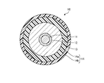
- FIG. 1 is a schematic cross-sectional view of an optical fiber according to an embodiment.
- FIG. 2 is a schematic diagram of the refractive index profile of the optical fiber according to the embodiment.
- FIG. 3 is a diagram showing an example of the relationship between ⁇ 1 and the cable cutoff wavelength.
- FIG. 4 is a diagram showing an example of the relationship between ⁇ 1 and bending loss.
- FIG. 5 is a diagram showing an example of the relationship between ( ⁇ 1 ⁇ 2) and bending loss.
- FIG. 6 is a diagram showing an example of the relationship between b/a, bending loss, and cable cutoff wavelength.
- FIG. 7 is a diagram showing an example of the relationship between ⁇ 1 and microbend loss.
- FIG. 8 is a diagram showing an example of the relationship between ⁇ 2 and microbend loss.
- FIG. 9 is a diagram showing an example of the relationship between ⁇ 1 and transmission loss.
- the cutoff wavelength or the effective cutoff wavelength refers to the ITU-T G.I. Refers to the cable cutoff wavelength ( ⁇ cc) defined in R.650.1. For other terms not specifically defined in this specification, see G.I. 650.1 and G.I. 650.2 shall comply with the definition and measurement method.
- FIG. 1 is a schematic cross-sectional view of an optical fiber according to an embodiment.
- the optical fiber 10 is made of silica-based glass, and includes a core portion 11 , a side core layer 12 surrounding the outer periphery of the core portion 11 , and a clad portion 13 surrounding the outer periphery of the side core layer 12 .
- a portion of the optical fiber 10 including the core portion 11, the side core layer 12, and the clad portion 13 is a portion made of glass in the optical fiber, and is sometimes referred to as a glass optical fiber.
- the optical fiber 10 also includes a coating layer 14 surrounding the outer circumference of the clad portion 13 .
- the coating layer 14 has a primary layer 14a surrounding the outer periphery of the clad portion 13 and a secondary layer 14b surrounding the outer periphery of the primary layer 14a.
- An optical fiber provided with the coating layer 14 may be described as an optical fiber core wire.
- FIG. 2 is a diagram showing the refractive index profile of the optical fiber 10.
- FIG. A profile P1 is a refractive index profile of the core portion 11 and has a so-called step shape.
- Profile P2 is the refractive index profile of the side core layer 12 .
- a profile P3 is a refractive index profile of the cladding portion 13 .
- the refractive index profile of the core portion 11 is not limited to a geometrically ideal step shape, but the shape of the top portion is not flat and unevenness is formed due to manufacturing characteristics. It may have a shape that pulls.
- the refractive index of the substantially flat region at the top of the refractive index profile within the range of the core diameter 2a of the core portion 11 in manufacturing design serves as an index for determining ⁇ 1.
- the substantially flat region seems to be divided into multiple places, or when it is difficult to define the substantially flat region due to a continuous change, At least any part of the core part other than the part where the rate changes is within the range of ⁇ 1 below, and the difference in ⁇ between the maximum value and the minimum value is within ⁇ 30% of a certain value, desired It has been confirmed that it is possible to produce characteristics close to , and there is no particular problem.
- the core diameter of the core portion 11 is 2a.
- the outer diameter of the side core layer 12 is 2b.
- the relative refractive index difference (maximum relative refractive index difference) of the average maximum refractive index of the core portion 11 with respect to the average refractive index of the clad portion 13 is ⁇ 1.
- the relative refractive index difference of the average refractive index of the side core layer 12 with respect to the average refractive index of the cladding portion 13 is ⁇ 2.
- the average maximum refractive index of the core portion 11 is the average value in the radial direction of the refractive index of the substantially flat region at the top of the refractive index profile.
- the average refractive index of the side core layer 12 and the clad portion 13 is the average value of the refractive indices in the radial direction of the refractive index profile.
- the relative refractive index difference of the average refractive index of the clad portion 13 with respect to the refractive index of pure silica glass is ⁇ Clad.
- pure silica glass is very high-purity silica glass that does not substantially contain dopants that change the refractive index and has a refractive index of about 1.444 at a wavelength of 1550 nm.
- the dashed-dotted line indicates the relative refractive index difference of the pure silica glass with respect to the average refractive index of the cladding portion 13 .
- the optical fiber 10 has a W-shaped refractive index profile.
- FIG. 2 shows the case where ⁇ Clad is a negative value of less than 0%, but ⁇ Clad may be 0% or more.
- the core portion 11 may be made of silica-based glass containing a refractive index adjusting dopant for increasing the refractive index.
- the core portion 11 contains at least one, for example two or more, of germanium (Ge), chlorine (Cl), fluorine (F), potassium (K) and sodium (Na) as a dopant. F lowers the refractive index of quartz glass, and (Ge), Cl, K and Na are dopants that raise the refractive index of quartz glass.
- the core portion 11 may not contain Ge. Not containing Ge includes both the case where the core portion 11 contains a dopant other than Ge and the case where the core portion 11 is made of pure silica glass. When the core portion 11 does not contain Ge, transmission loss due to Rayleigh scattering can be reduced.
- the side core layer 12 and the clad portion 13 are made of quartz-based glass doped with only F and Cl, only F, or only Cl.
- ⁇ 1> ⁇ Clad> ⁇ 2 and 0> ⁇ 2 are established, and preferable ranges of ⁇ 1, ⁇ 2, and ⁇ Clad, which will be described later, are realized.
- the clad portion 13 may be made of pure silica glass.
- the primary layer 14a and the secondary layer 14b are made of resin.
- This resin is, for example, an ultraviolet curing resin.
- the UV curable resin is a mixture of various resin materials and additives such as oligomers, diluent monomers, photopolymerization initiators, silane coupling agents, sensitizers and lubricants.
- oligomer conventionally known materials such as polyether urethane acrylate, epoxy acrylate, polyester acrylate, and silicone acrylate can be used.
- Conventionally known materials such as monofunctional monomers and polyfunctional monomers can be used as the diluent monomer.
- the additives are not limited to those described above, and conventionally known additives and the like used for ultraviolet curable resins and the like can be widely used.
- the primary layer thickness which is the layer thickness of the primary layer 14a
- the secondary layer thickness which is the layer thickness of the secondary layer 14b
- the primary elastic modulus which is the elastic modulus of the primary layer 14a
- the secondary elastic modulus which is the elastic modulus of the secondary layer 14b.
- Primary and secondary moduli are also called Young's moduli. These elastic moduli can be realized by adjusting the components of the resin, manufacturing conditions, and the like. Specifically, the types, molecular weights and contents of oligomers in the materials constituting the primary layer 14a and the secondary layer 14b, the types and amounts of diluent monomers, the types and contents of other components, the irradiation intensity of ultraviolet rays, etc.
- the elastic moduli of the primary layer 14a and the secondary layer 14b can be adjusted by the curing conditions and the like.
- ⁇ 1 is 0.18% or more and 0.24% or less
- ⁇ 2 is ⁇ 0.27% or more and ⁇ 0.12% or less
- ( ⁇ 1 ⁇ 2) is 0 36% or more and 0.45% or less
- b/a is 2.5 or more and 5 or less
- the effective core area at a wavelength of 1550 nm is 105 ⁇ m 2 or more and 130 ⁇ m 2 or less
- the cable cutoff wavelength is 1530 nm or less.
- the bending loss at a wavelength of 1550 nm when bent with a diameter of 30 mm is 1 dB/m or less.
- Aeff is a value at a wavelength of 1550 nm unless otherwise specified.
- the bending loss is a value at a wavelength of 1550 nm when bent with a diameter of 30 mm.
- FIG. 3 is a diagram showing an example of the relationship between ⁇ 1 and the cable cutoff wavelength ( ⁇ cc).
- the data in FIG. 3 is obtained by adjusting the core diameter 2a to a range in which Aeff is 120 ⁇ m 2 or more and 125 ⁇ m 2 or less, and ⁇ 2, which is another structural parameter, is ⁇ 0.27% or more and ⁇ 0.12% or less, b
- /a is changed in the range of 2.5 or more and 5 or less is shown.
- FIG. 3 shows the average ⁇ cc value for each ⁇ 1. From FIG.
- FIG. 4 is a diagram showing an example of the relationship between ⁇ 1 and bending loss.
- the data in FIG. 4 is obtained by adjusting the core diameter 2a to a range in which Aeff is 105 ⁇ m 2 or more and 130 ⁇ m 2 or less, and ⁇ 2, which is another structural parameter, is ⁇ 0.27% or more and ⁇ 0.12% or less, b /a is changed in the range of 2.5 to 5 and ⁇ cc is 1500 nm or less.
- the reason why ⁇ cc is set to 1500 nm or less is to ensure stable single-mode properties at wavelengths in the C band (for example, 1530 nm to 1565 nm) regardless of manufacturing variations of the optical fiber 10 .
- ⁇ 1 is preferably 0.18% or more , and 0 We have found that .20% or more is more preferable.
- FIG. 5 is a diagram showing an example of the relationship between ( ⁇ 1 ⁇ 2) and bending loss.
- the data in FIG. 5 are obtained when the core diameter 2a is adjusted to a range in which Aeff is 105 ⁇ m 2 or more and 130 ⁇ m 2 or less, and ⁇ 1 is adjusted in a range of 0.18% to 0.24%, and A case where ⁇ cc is 1500 nm or less is shown.
- the bending loss was obtained by widening the adjustment range of Aeff.
- the value of ( ⁇ 1- ⁇ 2) is also an important factor in bending loss.
- ⁇ 1 ⁇ 2 is preferably 0.36% or more. Also, when ⁇ 1 is 0.18% or more and 0.24% or less, if ⁇ 2 is less than -0.27%, even if other parameters are optimized, a solution that satisfies all of Aeff, ⁇ cc, and bending loss was found not to exist. Therefore, the preferred range of ⁇ 2 is -0.27% to -0.12%. The reason why ⁇ 2 is preferably ⁇ 0.12% or less will be described later.
- FIG. 6 is a diagram showing an example of the relationship between b/a, bending loss, and cable cutoff wavelength.
- the data in FIG. 6 are obtained by adjusting the core diameter 2a to a range where Aeff is 125 ⁇ m 2 or more and 130 ⁇ m 2 or less, ⁇ 1 is adjusted to a range of 0.18% or more and 0.24% or less, and other structures It shows the case where the parameter ⁇ 2 is changed in the range of ⁇ 0.27% or more and ⁇ 0.12% or less.
- Aeff was adjusted to a range of 125 ⁇ m 2 or more and 130 ⁇ m 2 or less because a value close to the upper limit of 105 ⁇ m 2 or more and 130 ⁇ m 2 or less is a condition in which bending loss tends to increase, that is, a condition in which it is more difficult to achieve low bending loss. It is for
- the bending loss decreases as b/a increases, and when b/a is 2.5 or more, it is easy to achieve a bending loss of 1 dB/m or less.
- a bending loss of 1 dB/m or less can be easily achieved even with a smaller b/a, but when Aeff is 2.5 or more, it tends to stably be 1 dB/m or less, which is preferable.
- b/a is greater than 3.9, the degree of decrease in bending loss due to the increase in b/a is small, so b/a may be 3.9 or less.
- ⁇ cc As can be seen from FIG. 6, it is difficult to achieve ⁇ cc of 1530 nm when b/a is 4 or more in the range of Aeff from 125 ⁇ m 2 to 130 ⁇ m 2 . Therefore, b/a is more preferably 3.9 or less. It was also confirmed that in the range where Aeff is smaller, 1530 nm or less can be realized when b/a is 5 or less.
- Microbend loss is also an important factor in an optical fiber with extended Aeff, like bending loss (macrobend loss). Therefore, simulation calculations and experiments were conducted to study the microbend loss when a sandpaper method similar to the fixed diameter drum method defined in JIS C6823:2010 is applied. The measurement wavelength of microbend loss was set to 1550 nm. A simulation calculation based on the following non-patent document was used to investigate the microbending loss: "Tamas Mihalffy et al., Combined Mechanical-Optical Simulation to Predict Microbending Loss of Single Mode Fibers, OECC 2019, WP4-C1".
- a fixed diameter bobbin wrapped with #1000 sandpaper was wound with a tension of 100 gf, and a 500 m long optical fiber was wound in a single layer 12 so as not to overlap each other.
- the difference between the transmission loss of the optical fiber to be measured in A and the transmission loss of the optical fiber in the state B in which no lateral pressure is applied was defined as the value of the microbend loss.
- FIG. 7 is a diagram showing an example of the relationship between ⁇ 1 and microbend loss.
- the data in FIG. 7 are obtained by adjusting the core diameter 2a to a range in which Aeff is 125 ⁇ m 2 or more and 130 ⁇ m 2 or less, and b/a is 3.0, 3.2, 3.4, 3.6, 3.0 ⁇ m 2 . 8 and 4.0, and ⁇ 2, which is another structural parameter, is changed in the range of ⁇ 0.27% to ⁇ 0.12%.
- FIG. 7 shows the average value of microbending loss for each ⁇ 1.
- FIG. 8 is a diagram showing an example of the relationship between ⁇ 2 and microbend loss.
- the data in FIG. 8 are obtained by adjusting the core diameter 2a in the range where Aeff is 125 ⁇ m 2 or more and 130 ⁇ m 2 or less, changing ⁇ 1 in the range of 0.18% or more and 0.24% or less, and b/a The case where it is changed in the range of 3.0 or more and less than 4.0 is shown.
- FIG. 8 shows the average microbend loss values for each ⁇ 2.
- ⁇ 2 is preferably ⁇ 0.12% or less.
- ⁇ 2 is preferably ⁇ 0.14% or less.
- the present inventor conducted exhaustive studies as described above and found that the cable cutoff wavelength is 1530 nm or less, the Aeff is 105 ⁇ m 2 or more and 130 ⁇ m 2 or less at the wavelength 1550 nm, the bending loss is 1 dB/m or less, and the micro A combination of structural parameters has been found that satisfies the condition that the bend loss is 1 dB/km or less.
- the results of the study on transmission loss will be explained.
- the optical fiber produced as a trial was manufactured according to a conventionally known method for manufacturing an optical fiber, which will be described later.
- Fluorine (F) was added to the clad to make ⁇ Clad a negative value.
- a small amount of dopant was added to the core portion to make the refractive index approximately the same as that of pure silica glass.
- ⁇ 1 was changed by changing the amount of dopant to the core portion.
- FIG. 9 is a diagram showing an example of the relationship between ⁇ 1 and transmission loss. Here, even with the same ⁇ 1, different values of transmission loss are obtained depending on the values of other structural parameters, so FIG. 9 shows average values of transmission loss for each ⁇ 1.
- the transmission loss changes according to the change in ⁇ 1 due to the change in the amount of dopant.
- ⁇ 1 is larger than 0.24%, the amount of F added to the clad increases, and the viscosity of the clad decreases, which tends to apply excessive stress to the core, and the transmission loss tends to increase. It turned out to be
- ⁇ 1 is preferably 0.18% or more and 0.24% or less also from the viewpoint of transmission loss. Furthermore, in order to achieve a transmission loss of less than 0.165 dB/km, it has been found that ⁇ 1 preferably satisfies 0.19% ⁇ 1 ⁇ 0.24%.
- the optical fiber 10 achieves both single-mode property and low bending loss while moderately expanding Aeff, and furthermore has low microbend loss. Further, as can be seen from FIG. 9, the optical fiber 10 can have a transmission loss of 0.18 dB/km or less at a wavelength of 1550 nm.
- the optical fiber 10 As a method for manufacturing the optical fiber 10, it is desirable to manufacture the optical fiber using a known manufacturing method so as to satisfy the above structural parameters and characteristics of the resin layer.
- the optical fiber 10 is formed by a known method such as a VAD (Vapor Axial Deposition) method, an OVD (Outside Vapor Deposition) method, an MCVD (Modified Chemical Vapor Deposition) method, or a plasma CVD method.
- VAD Very Axial Deposition
- OVD Outside Vapor Deposition
- MCVD Modified Chemical Vapor Deposition
- a glass optical fiber is drawn from this optical fiber preform in a drawing furnace, a resin is applied to the drawn glass optical fiber, and the resin is irradiated with ultraviolet rays to be cured. can.
- dopants such as Ge, F, K, and Na can be added to the optical fiber preform by using a gas containing the dopant when synthesizing the soot.
- K and Na may be doped into the glass by a vapor phase method, a liquid immersion method, or the like, not during soot synthesis, by utilizing their diffusion speed.
- Cl can be added to the optical fiber preform by leaving the chlorine gas used in the dehydration step.
- F can be added to the optical fiber preform by flowing fluorine gas in a vitrified sintering configuration.
- Example 2 As an example, an optical fiber preform manufactured using the VAD method was drawn, and sample No. 1 having a W-shaped refractive index profile was obtained. 1 to 10 optical fibers were manufactured.
- the core portion is made of silica-based glass having a slightly higher or slightly lower refractive index than that of pure silica glass by adding one or more kinds of Cl, K, Na, and F.
- the cladding portion was made of silica-based glass doped with F, which is a dopant that lowers the refractive index.
- the diameter (cladding diameter) of the glass optical fiber was set to 125 ⁇ m.
- the thickness of the coating layer was about 250 ⁇ m.
- process conditions such as the VAD method and wire drawing were optimized each time according to the core dopant added to the core portion. For example, tension during drawing was optimized by drawing furnace temperature and drawing speed.
- sample No. The optical properties of 1-10 optical fibers were measured.
- the sandpaper method was used as the method for measuring the microbend loss. That is, an optical fiber with a length of 500 m is wound in a single layer with a tension of 100 gf on a fixed bobbin wrapped with #1000 sandpaper so as not to overlap each other.
- the difference between the loss and the transmission loss of the optical fiber in state B in which no lateral pressure is applied was defined as the value of the microbend loss.
- the measurement wavelength is 1550 nm.
- Table 2 shows the optical properties of each sample.
- ⁇ 1′ is the average maximum relative refractive index difference of the core portion with respect to the refractive index of pure silica glass.
- the core dopant for example, “Cl 2 +K” means doping with chlorine and potassium.
- ⁇ 1 is 0.18% or more and 0.24% or less
- ⁇ 2 is ⁇ 0.27% or more and ⁇ 0.12% or less
- ( ⁇ 1 ⁇ 2) is 0.36% 0.45% or less
- b/a was 2.5 or more and 5 or less
- 2a was 12 ⁇ m or more and 13.9 ⁇ m or less.
- sample No. for 1 ⁇ 1 is 0.24%, ⁇ 2 is ⁇ 0.12%, ( ⁇ 1 ⁇ 2) is 0.36%, b/a is 2.8, 2a is 13.3 ⁇ m, and the core dopant is Cl 2 .
- Aeff was 122 ⁇ m 2
- ⁇ cc was 1416 nm
- bending loss was 0.58 dB/m
- transmission loss was 0.168 dB/km
- microbending loss was 0.58 dB/km. It was a particularly preferable example from the balance of
- sample no. For 2 ⁇ 1 is 0.23%, ⁇ 2 is ⁇ 0.15%, ( ⁇ 1 ⁇ 2) is 0.38%, b/a is 2.9, 2a is 13.3 ⁇ m, and the core dopant is Cl 2 +K.
- Aeff was 120 ⁇ m 2
- ⁇ cc was 1368 nm
- bending loss was 0.39 dB/m
- transmission loss was 0.152 dB/km
- microbending loss was 0.36 dB/km. It was a particularly preferable example from the balance with.
- sample no. for 10 ⁇ 1 is 0.22%, ⁇ 2 is ⁇ 0.15%, ( ⁇ 1 ⁇ 2) is 0.37%, b/a is 2.5, 2a is 13.9 ⁇ m, and the core dopant is Cl 2 +K+F.
- Aeff was 130 ⁇ m 2
- ⁇ cc was 1510 nm
- bending loss was 0.16 dB/m
- transmission loss was 0.155 dB/km
- microbend loss was 0.91 dB/km. It was a particularly preferable example from the balance with.
- microbend loss varies depending on the measurement method. Therefore, ITU-T G.I.
- the present invention is not limited by the above embodiments.
- the present invention also includes those configured by appropriately combining the respective constituent elements described above. Further effects and modifications can be easily derived by those skilled in the art. Therefore, broader aspects of the present invention are not limited to the above-described embodiments, and various modifications are possible.
- optical fiber 11 core portion 12: side core layer 13: clad portion 14: coating layer 14a: primary layer 14b: secondary layers P1, P2, P3: profile
Abstract
Priority Applications (4)
| Application Number | Priority Date | Filing Date | Title |
|---|---|---|---|
| JP2023512968A JPWO2022215603A1 (fr) | 2021-04-08 | 2022-03-29 | |
| EP22784587.2A EP4321910A1 (fr) | 2021-04-08 | 2022-03-29 | Fibre optique |
| CN202280024486.5A CN117120898A (zh) | 2021-04-08 | 2022-03-29 | 光纤 |
| US18/481,336 US20240027679A1 (en) | 2021-04-08 | 2023-10-05 | Optical fiber |
Applications Claiming Priority (2)
| Application Number | Priority Date | Filing Date | Title |
|---|---|---|---|
| JP2021065905 | 2021-04-08 | ||
| JP2021-065905 | 2021-04-08 |
Related Child Applications (1)
| Application Number | Title | Priority Date | Filing Date |
|---|---|---|---|
| US18/481,336 Continuation US20240027679A1 (en) | 2021-04-08 | 2023-10-05 | Optical fiber |
Publications (1)
| Publication Number | Publication Date |
|---|---|
| WO2022215603A1 true WO2022215603A1 (fr) | 2022-10-13 |
Family
ID=83545457
Family Applications (1)
| Application Number | Title | Priority Date | Filing Date |
|---|---|---|---|
| PCT/JP2022/015633 WO2022215603A1 (fr) | 2021-04-08 | 2022-03-29 | Fibre optique |
Country Status (5)
| Country | Link |
|---|---|
| US (1) | US20240027679A1 (fr) |
| EP (1) | EP4321910A1 (fr) |
| JP (1) | JPWO2022215603A1 (fr) |
| CN (1) | CN117120898A (fr) |
| WO (1) | WO2022215603A1 (fr) |
Citations (9)
| Publication number | Priority date | Publication date | Assignee | Title |
|---|---|---|---|---|
| JPH02451B2 (fr) | 1980-09-13 | 1990-01-08 | Hoechst Ag | |
| JPH0227973B2 (fr) | 1981-10-02 | 1990-06-20 | Basf Ag | |
| WO2000062106A1 (fr) * | 1999-04-13 | 2000-10-19 | Sumitomo Electric Industries, Ltd. | Fibre optique et systeme de communication optique comprenant celle-ci |
| JP2003066259A (ja) | 2001-08-29 | 2003-03-05 | Hitachi Cable Ltd | 波長多重伝送用低非線形光ファイバ |
| JP2009122277A (ja) | 2007-11-13 | 2009-06-04 | Furukawa Electric Co Ltd:The | 光ファイバおよび光伝送システム |
| JP2011197667A (ja) * | 2010-02-26 | 2011-10-06 | Sumitomo Electric Ind Ltd | 光ファイバ及びそれを含む光通信システム |
| US20130114935A1 (en) * | 2011-11-04 | 2013-05-09 | Dana Craig Bookbinder | Bend loss resistant multi-mode fiber |
| JP2013518312A (ja) * | 2010-01-29 | 2013-05-20 | コーニング インコーポレイテッド | 大有効面積無Geコアファイバ |
| WO2015186719A1 (fr) * | 2014-06-05 | 2015-12-10 | 住友電気工業株式会社 | Fibre optique |
-
2022
- 2022-03-29 EP EP22784587.2A patent/EP4321910A1/fr active Pending
- 2022-03-29 WO PCT/JP2022/015633 patent/WO2022215603A1/fr active Application Filing
- 2022-03-29 CN CN202280024486.5A patent/CN117120898A/zh active Pending
- 2022-03-29 JP JP2023512968A patent/JPWO2022215603A1/ja active Pending
-
2023
- 2023-10-05 US US18/481,336 patent/US20240027679A1/en active Pending
Patent Citations (9)
| Publication number | Priority date | Publication date | Assignee | Title |
|---|---|---|---|---|
| JPH02451B2 (fr) | 1980-09-13 | 1990-01-08 | Hoechst Ag | |
| JPH0227973B2 (fr) | 1981-10-02 | 1990-06-20 | Basf Ag | |
| WO2000062106A1 (fr) * | 1999-04-13 | 2000-10-19 | Sumitomo Electric Industries, Ltd. | Fibre optique et systeme de communication optique comprenant celle-ci |
| JP2003066259A (ja) | 2001-08-29 | 2003-03-05 | Hitachi Cable Ltd | 波長多重伝送用低非線形光ファイバ |
| JP2009122277A (ja) | 2007-11-13 | 2009-06-04 | Furukawa Electric Co Ltd:The | 光ファイバおよび光伝送システム |
| JP2013518312A (ja) * | 2010-01-29 | 2013-05-20 | コーニング インコーポレイテッド | 大有効面積無Geコアファイバ |
| JP2011197667A (ja) * | 2010-02-26 | 2011-10-06 | Sumitomo Electric Ind Ltd | 光ファイバ及びそれを含む光通信システム |
| US20130114935A1 (en) * | 2011-11-04 | 2013-05-09 | Dana Craig Bookbinder | Bend loss resistant multi-mode fiber |
| WO2015186719A1 (fr) * | 2014-06-05 | 2015-12-10 | 住友電気工業株式会社 | Fibre optique |
Non-Patent Citations (1)
| Title |
|---|
| TAMAS MIHALFFY ET AL., COMBINED MECHANICAL-OPTICAL SIMULATION TO PREDICT MICROBENDING LOSS OF SINGLE MODE FIBERS, OECC 2019, WP4-C1 |
Also Published As
| Publication number | Publication date |
|---|---|
| CN117120898A (zh) | 2023-11-24 |
| US20240027679A1 (en) | 2024-01-25 |
| JPWO2022215603A1 (fr) | 2022-10-13 |
| EP4321910A1 (fr) | 2024-02-14 |
Similar Documents
| Publication | Publication Date | Title |
|---|---|---|
| JP7190236B2 (ja) | フッ素および塩素が共ドープされたコア領域を有する低損失光ファイバ | |
| US10571628B2 (en) | Low loss optical fiber with core codoped with two or more halogens | |
| JP6298893B2 (ja) | 損失低下を示す、台形コアを有するシングルモードファイバ | |
| JP6527973B2 (ja) | 光ファイバ | |
| US6205279B1 (en) | Single mode optical fiber having multi-step core structure and method of fabricating the same | |
| JP2012027454A (ja) | 単一モード光ファイバおよび光システム | |
| JP2011059687A (ja) | 改善した曲げ損失を有するマルチモード光ファイバ | |
| JP5416059B2 (ja) | 光ファイバ | |
| US20160209585A1 (en) | Optical fiber and manufacturing method thereof | |
| CN114325928B (zh) | 一种低损耗抗弯曲单模光纤 | |
| JP2003004973A (ja) | 光ファイバカプラ及び光ファイバカプラ用の光ファイバ | |
| WO2022215603A1 (fr) | Fibre optique | |
| CN110954985A (zh) | 一种超低衰减大有效面积单模光纤 | |
| US11714228B2 (en) | Optical fiber and method of manufacturing optical fiber | |
| WO2022210355A1 (fr) | Fibre optique | |
| CN111527430B (zh) | 光纤 | |
| CN114641714A (zh) | 光纤 | |
| WO2023085134A1 (fr) | Fibre optique | |
| WO2023112968A1 (fr) | Fibre optique | |
| WO2023054620A1 (fr) | Fibre optique et son procédé de fabrication | |
| WO2022158496A1 (fr) | Fibre optique, ruban de fibre optique et câble à fibre optique | |
| WO2022131161A1 (fr) | Fibre optique, procédé de conception de fibre optique et procédé de fabrication de fibre optique | |
| WO2023042769A1 (fr) | Fibre optique | |
| JP2023101891A (ja) | 光ファイバ | |
| WO2016129367A1 (fr) | Fibre optique à dispersion décalée |
Legal Events
| Date | Code | Title | Description |
|---|---|---|---|
| 121 | Ep: the epo has been informed by wipo that ep was designated in this application |
Ref document number: 22784587 Country of ref document: EP Kind code of ref document: A1 |
|
| WWE | Wipo information: entry into national phase |
Ref document number: 2023512968 Country of ref document: JP |
|
| WWE | Wipo information: entry into national phase |
Ref document number: 2022784587 Country of ref document: EP |
|
| NENP | Non-entry into the national phase |
Ref country code: DE |
|
| ENP | Entry into the national phase |
Ref document number: 2022784587 Country of ref document: EP Effective date: 20231108 |