WO2022215369A1 - 電動機及び電動送風機 - Google Patents
電動機及び電動送風機 Download PDFInfo
- Publication number
- WO2022215369A1 WO2022215369A1 PCT/JP2022/006726 JP2022006726W WO2022215369A1 WO 2022215369 A1 WO2022215369 A1 WO 2022215369A1 JP 2022006726 W JP2022006726 W JP 2022006726W WO 2022215369 A1 WO2022215369 A1 WO 2022215369A1
- Authority
- WO
- WIPO (PCT)
- Prior art keywords
- brush
- rotating shaft
- electric motor
- commutator
- rotor
- Prior art date
- Legal status (The legal status is an assumption and is not a legal conclusion. Google has not performed a legal analysis and makes no representation as to the accuracy of the status listed.)
- Ceased
Links
Images



Classifications
-
- H—ELECTRICITY
- H02—GENERATION; CONVERSION OR DISTRIBUTION OF ELECTRIC POWER
- H02K—DYNAMO-ELECTRIC MACHINES
- H02K23/00—DC commutator motors or generators having mechanical commutator; Universal AC/DC commutator motors
-
- H—ELECTRICITY
- H02—GENERATION; CONVERSION OR DISTRIBUTION OF ELECTRIC POWER
- H02K—DYNAMO-ELECTRIC MACHINES
- H02K23/00—DC commutator motors or generators having mechanical commutator; Universal AC/DC commutator motors
- H02K23/54—Disc armature motors or generators
-
- H—ELECTRICITY
- H02—GENERATION; CONVERSION OR DISTRIBUTION OF ELECTRIC POWER
- H02K—DYNAMO-ELECTRIC MACHINES
- H02K5/00—Casings; Enclosures; Supports
- H02K5/04—Casings or enclosures characterised by the shape, form or construction thereof
- H02K5/16—Means for supporting bearings, e.g. insulating supports or means for fitting bearings in the bearing-shields
- H02K5/173—Means for supporting bearings, e.g. insulating supports or means for fitting bearings in the bearing-shields using bearings with rolling contact, e.g. ball bearings
Definitions
- the present disclosure relates to electric motors and electric blowers.
- Electric motors are widely used not only in the field of household electric appliances, but also in the field of electrical equipment such as automobiles.
- an electric motor is used as a cooling fan for cooling a radiator, a condenser, or the like.
- An object of the present disclosure is to provide an electric motor having a coreless rotor and an electric blower capable of stably supporting a rotating shaft with one ball bearing.
- one aspect of the electric motor according to the present disclosure includes: a rotor having a rotating shaft and coils extending in an axial direction; a commutator attached to the rotating shaft; at least one brush in contact with the commutator; a brush spring for pressing the at least one brush against the commutator; , is a constant force spring.
- the rotor may be a coreless rotor that does not have a core.
- One aspect of the electric blower according to the present disclosure includes the electric motor described above and a rotating fan attached to the rotating shaft of the electric motor, and the rotating fan includes the bearing and the commutator on the rotating shaft. It is attached to the end on the bearing side.
- FIG. 1 is an external perspective view of an electric motor according to an embodiment.
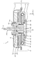
- FIG. 2 is a cross-sectional view (XZ cross-sectional view) of the electric motor according to the embodiment.
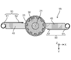
- FIG. 3 is a cross-sectional view (XY cross-sectional view) of the electric motor according to the embodiment.
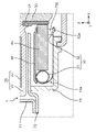
- FIG. 4 is a partially enlarged cross-sectional view of the electric motor according to the embodiment.
- FIG. 5 is a diagram showing the arrangement of brush springs of an electric motor according to a modification.
- FIG. 6 is a conceptual diagram of the electric blower according to the embodiment.
- the X-axis, Y-axis and Z-axis represent three axes of a three-dimensional orthogonal coordinate system.
- the X-axis and the Y-axis are orthogonal to each other and both orthogonal to the Z-axis.
- the Z-axis direction is the direction of the axis C of the rotating shaft 21 .
- each figure is a schematic diagram and is not necessarily strictly illustrated. Moreover, in each figure, the same code
- FIG. 1 is an external perspective view of an electric motor 1 according to an embodiment.
- 2 and 3 are sectional views of the electric motor 1.
- FIG. FIG. 2 shows a cross section (XZ cross section passing through the brush 40) taken along a plane passing through the axis C of the rotating shaft 21 and passing through the brush 40.
- FIG. FIG. 3 shows a cross section (XY cross section passing through the brush 40) taken along a plane passing through the brush 40 and having the axis C of the rotating shaft 21 as a vertical line.
- FIG. 4 is an enlarged cross-sectional view of a region IV surrounded by broken lines in FIG.
- FIG. 6 is a conceptual diagram of the electric blower 90 according to the embodiment.
- the electric blower 90 includes an electric motor 1 and a rotating fan 91.
- the rotating fan 91 is attached to the rotating shaft 21 of the electric motor 1 .
- the rotating fan 91 is attached to the bearing-side end of the bearing and the commutator on the rotating shaft 21 .
- the motor 1 is a commutator motor with brushes.
- the electric motor 1 includes a stator 10 (stator), a rotor 20 (rotor), a commutator 30 , at least one brush 40 , brush springs 50 and bearings 60 .
- the rotor 20 is rotated by the magnetic force of the stator 10 .
- the commutator 30 is attached to the rotating shaft 21 of the rotor 20 .
- the brushes 40 are in sliding contact with the commutator 30 .
- the brush spring 50 is for pressing the brush 40 against the commutator 30 .
- Bearing 60 supports rotating shaft 21 of rotor 20 . In the following description, a pair of brushes 40 will be exemplified.
- the electric motor 1 further includes a motor case 70 that forms an outer casing of the electric motor 1 and a cover plate 80 that covers the brushes 40 .
- the motor case 70 has a first member 71 , a second member 72 , a third member 73 and a fourth member 74 .
- the electric motor 1 is a type of direct current motor (DC motor) driven by direct current.
- a magnet is used as the stator 10 in the electric motor 1 .
- An armature having a coil 22 is used as the rotor 20 in the electric motor 1 .
- the electric motor 1 is a flat brushed coreless motor (flat motor) mounted on a vehicle such as a two-wheeled vehicle or a four-wheeled vehicle. Therefore, the stator 10 and the rotor 20 do not have a core (iron core), and the electric motor 1 as a whole is thin and light. Specifically, the electric motor 1 is a small motor used for a radiator cooling fan in a vehicle.
- the outer diameter (diameter) of the electric motor 1 is ⁇ 120 mm or less. As an example, the outer diameter of the electric motor 1 is ⁇ 60 mm, ⁇ 70 mm, ⁇ 90 mm, or the like.
- the stator 10 is arranged with a minute air gap between it and the rotor 20 .
- the stator 10 generates magnetic force acting on the rotor 20 .
- the stator 10 is configured to generate magnetic flux on the air gap surface with the rotor 20 .
- the stator 10 forms a magnetic circuit together with the rotor 20, which is an armature.
- the stator 10 as a whole has a substantially donut shape.
- the stator 10 is configured such that N poles and S poles alternately and evenly exist on the air gap surface with the rotor 20 along the circumferential direction of the rotating shaft 21 .
- the stator 10 is a magnetic field that creates magnetic flux for generating torque.
- the stator 10 is composed of a plurality of magnets (magnets).
- the magnets forming the stator 10 are, for example, permanent magnets.
- the direction of the main magnetic flux generated by the stator 10 (magnet) is along the axial center C direction along which the rotating shaft 21 extends. Note that the stator 10 is fixed to the first member 71 of the motor case 70 .
- the rotor 20 has a rotating shaft 21 and coils 22 .
- Rotor 20 is a coreless rotor that does not have a core.
- the rotor 20 rotates around the direction of the axis C along which the rotating shaft 21 extends. Rotor 20 generates a magnetic force acting on stator 10 .
- the direction of the main magnetic flux generated by the rotor 20 is along the axial center C direction along which the rotating shaft 21 extends.
- the rotor 20 is arranged facing the stator 10 .
- the rotor 20 faces the stator 10 in the axial center C direction along which the rotating shaft 21 extends.
- the coil 22 of the rotor 20 and the stator 10 face each other in the direction of the axis C along which the rotating shaft 21 extends. That is, the coil 22 and the stator 10 are arranged in the direction of the axis C of the rotating shaft 21 .
- the rotating shaft 21 is a shaft having an axis C.
- the rotating shaft 21 is an elongated rod-shaped member.
- the rotating shaft 21 is a metal rod made of a metal material such as SUS (Stainless Used Steel).
- An axis C included in the rotating shaft 21 is the center of rotation of the rotor 20 .
- the longitudinal direction of the rotating shaft 21, that is, the direction in which the rotating shaft 21 extends (stretching direction) is the direction of the axis C (also referred to simply as the "axis direction").
- the rotary shaft 21 is supported by one bearing 60. That is, there is only one bearing 60 that supports the rotating shaft 21 .
- the bearing 60 rotatably supports the rotating shaft 21 .
- Bearing 60 is a ball bearing. Specifically, bearing 60 is a deep groove ball bearing.
- the first end 21a of the rotating shaft 21 is the output-side end (output shaft).
- the first end portion 21 a protrudes from the first member 71 of the motor case 70 and the bearing 60 .
- the first end portion 21 a is the end portion of the bearing 60 and the commutator 30 on the rotating shaft 21 on the bearing 60 side.
- a load such as a rotating fan is attached to the first end portion 21a.
- Electric motor 1 in which a rotating fan is attached to rotating shaft 21 can be used, for example, as a cooling fan.
- the second end 21b of the rotary shaft 21 is the end (counter-output shaft) on the non-output side. The second end 21 b does not protrude from the motor case 70 .
- the coils 22 of the rotor 20 are wound coils.
- the rotor 20 has multiple coils 22 .
- the multiple coils 22 are armature windings configured by electric wires.
- the plurality of coils 22 are wound so as to generate magnetic force acting on the stator 10 when current flows.
- the direction of the main magnetic flux generated by each coil 22 is the axial center C direction along which the rotating shaft 21 extends.
- the plurality of coils 22 are wound in a flat shape, and arranged in a posture in which the coil surfaces face the axial center C direction along which the rotating shaft 21 extends.
- Each coil 22 is composed of an insulating covered wire having a core wire made of metal such as copper or aluminum and an insulating film covering the core wire.
- the plurality of coils 22 are thin wound coils having coil layers in which the insulated wires are wound in a plane.
- the plurality of coils 22 are configured by, for example, one or a plurality of coil layers in which an insulated wire is wound in a generally fan shape in a plan view.
- the plurality of coils 22 configured in this way are arranged so as to surround the rotating shaft 21 when viewed from the axial center C direction along which the rotating shaft 21 extends.
- the multiple coils 22 are electrically connected to the commutator 30 . Specifically, each of the multiple coils 22 is electrically connected to one of the multiple commutator segments 31 of the commutator 30 . Therefore, current flows through each of the plurality of coils 22 via the commutator segments 31 with which the brushes 40 are in contact.
- a plurality of coils 22 are covered with molding resin 23 . That is, the plurality of coils 22 are integrally formed with the mold resin 23 by being covered with the mold resin 23 .
- the outer shape of the mold resin 23 after molding the plurality of coils 22 is circular in plan view.
- the mold resin 23 is made of an insulating resin material such as phenol resin or unsaturated polyester (Bulk Molding Compound, BMC).
- the mold resin 23 may be either thermosetting resin or thermoplastic resin.
- the commutator 30 is attached to the rotating shaft 21 . Therefore, the commutator 30 rotates together with the rotating shaft 21 as the rotor 20 rotates.
- the commutator 30 is attached to the second end 21b of the rotating shaft 21 .
- a commutator 30 attached to the rotating shaft 21 may be part of the rotor 20 .
- the commutator 30 and the bearing 60 are located on opposite sides in the direction of the axis C along which the rotating shaft 21 extends, with the position of the coil 22 on the rotating shaft 21 as a reference. Since rotor 20 does not have a core, commutator 30 and bearing 60 are arranged close to each other. Note that the bearing 60 is positioned at the center of the rotating shaft 21 over the entire rotating shaft 21 including the portion protruding from the motor case 70 .
- the commutator 30 has a plurality of commutator pieces 31 (commutator segments) provided along the rotating direction of the rotating shaft 21 .
- the plurality of commutator segments 31 are annularly arranged along the rotation direction of the rotation shaft 21 so as to surround the rotation shaft 21 .
- Each commutator piece 31 is an elongated member extending in the longitudinal direction of the rotating shaft 21 .
- the plurality of commutator segments 31 are conductive terminals made of a metal material such as copper.
- the multiple commutator segments 31 are electrically connected to the coils 22 of the rotor 20 .
- the plurality of commutator segments 31 are arranged insulated from each other. However, the multiple commutator segments 31 are electrically connected by the coils 22 of the rotor 20 .
- the commutator 30 is a molded commutator.
- the commutator 30 has a configuration in which a plurality of commutator segments 31 are molded with molding resin. In this case, the plurality of commutator segments 31 are embedded in the molding resin so that their surfaces are exposed.
- the mold resin is the commutator body.
- the mold resin is a substantially tubular member having a through hole into which the rotary shaft 21 is inserted.
- the mold resin is, for example, a resin molded body made of an insulating resin material such as a thermosetting resin.
- At least one brush 40 is in contact with the commutator 30 .
- the tip of the brush 40 is in contact with the commutator piece 31 of the commutator 30 . Since the commutator 30 rotates as the rotating shaft 21 rotates, the brush 40 keeps contacting all the commutator segments 31 sequentially.
- the brush 40 is a power supply brush for supplying power to the coil 22. Specifically, the brushes 40 supply power to the coils 22 by contacting the commutator segments 31 of the commutator 30 .
- the brush 40 is connected to a power terminal fixed to the motor case 70 by a pigtail wire. When the brushes 40 come into contact with the commutator segments 31 , the armature current supplied from the power supply terminals to the brushes 40 flows through the coils 22 via the commutator segments 31 .
- the brush 40 is a conductive carbon brush made of carbon.
- the brush 40 is an elongated substantially rectangular parallelepiped.
- a plurality of brushes 40 are provided. In this case, it is preferable that a plurality of brushes 40 are provided at regular intervals along the rotation direction of the rotor 20 .
- two brushes 40 are provided. The two brushes 40 are arranged to face each other with the commutator 30 interposed therebetween. That is, as shown in FIG. 3, the two brushes 40 are arranged at intervals of 180 degrees along the rotation direction of the rotor 20. As shown in FIG.
- the brushes 40 are always in contact with the commutator segments 31 of the commutator 30 under pressure from the brush springs 50 . That is, the brushes 40 are pressed against the commutator 30 by the brush springs 50 . In this manner, the brushes 40 receive the pressing force from the brush springs 50 and come into sliding contact with the commutator 30 .
- the brush 40 is arranged so as to be movable in a direction (radial direction) intersecting with the axial center C direction along which the rotating shaft 21 extends due to wear with the commutator 30 .
- the brush spring 50 presses the brush 40 against the commutator 30 by applying pressure to the brush 40 .
- the brush spring 50 applies pressure (spring pressure) to the brush 40 by spring elastic force (spring restoring force) to urge the brush 40 toward the commutator 30 .
- a brush spring 50 is provided for each brush 40 . In this embodiment, since two brushes 40 are used, two brush springs 50 are also used.
- the brush spring 50 is a constant force spring. Therefore, the brush spring 50 applies a uniform load to the brush 40 . That is, the brush spring 50, which is a constant force spring, applies a uniform pressing force to the brush 40. As shown in FIG.
- the brush spring 50 which is a constant load spring, is made of a strip-shaped wire rod.
- the brush spring 50 which is a constant force spring, is a spiral spring.
- a brush spring 50 which is a constant force spring, has a spiral portion 51 (coil portion) in which a strip-shaped wire rod is spirally wound.
- the brush spring 50 which is a constant force spring, is made of, for example, a strip-shaped wire rod made of a metal material or the like.
- the brush spring 50 which is a constant force spring, is made of a long strip-shaped metal plate. Therefore, the spiral portion 51 is a portion of the constant force spring in which a long strip-shaped metal plate is spirally wound multiple times only in one direction.
- the brush spring 50 which is a constant load spring, generates a force (spring restoring force) to return to the original spiral state by extending one end of the wire rod from the spiral portion 51 of the spiral.
- the brush spring 50 presses the brush 40 against the commutator 30 with the spiral portion 51 .
- the brush spring 50 applies a load to the brush 40 by the spring restoring force of the spiral portion 51 when the spiral portion 51 contacts the rear end portion of the brush 40 .
- the load with which the brush springs 50 press the brushes 40 against the commutator 30 is preferably at least 1 time the radial load generated during the rotation of the rotor 20 .
- the brush spring 50 is arranged so that the spiral axis of the spiral portion 51 and the axial center C direction along which the rotating shaft 21 extends are perpendicular to each other.
- the brush spring 50 is installed such that the spiral portion 51 is placed vertically.
- a spiral surface (coil surface) of the spiral portion 51 is parallel to an axis C included in the rotating shaft 21 .
- the motor case 70 houses the stator 10, the coils 22 of the rotor 20, the commutator 30, the brushes 40, the brush springs 50 and the bearings 60.
- the motor case 70 has the first member 71 , the second member 72 , the third member 73 and the fourth member 74 as described above.
- the first member 71, the second member 72, the third member 73, and the fourth member 74 are made of a ferrous material such as a cold-rolled steel plate (Steel Plate Cold Commercial, SPC material) or a metal material such as aluminum. Alternatively, it may be made of an insulating resin material. In this embodiment, the first member 71, the second member 72 and the third member 73 are made of metal material.
- the third member 73 is made of an insulating resin material.
- the first member 71 is an outer shell member forming part of the outer shell of the electric motor 1 .
- the first member 71 is formed in a flat, substantially bottomed cylindrical shape having a circular bottom and a thin cylindrical side wall.
- the first member 71 also functions as a bracket holding the stator 10 and the bearing 60 .
- the stator 10 is fixed to the bottom of the first member 71 .
- the bearing 60 is fixed in a recess 71 a provided in the center of the bottom of the first member 71 .
- the bearing 60 is press-fitted into the recess 71a of the first member 71 (bracket).
- the rotating shaft 21 is press-fitted into the bearing 60 . That is, the bearing 60 is in a state in which both the inner ring and the outer ring are press-fitted.
- the bearing 60 is fixed to the first member 71 by press-fitting the bearing 60 into the concave portion 71 a of the first member 71 .
- the rotary shaft 21 to which the commutator 30 and the resin-molded coil 22 are attached is press-fitted into the bearing 60 fixed to the first member 71 .
- the second member 72 is a thin plate member.
- the second member 72 is arranged between the first member 71 and the third member 73 in the axial center C direction of the rotating shaft 21 .
- the stator 10 and the coils 22 of the rotor 20 are arranged between the first member 71 and the second member 72 .
- the third member 73 is an outer shell member forming part of the outer shell of the electric motor 1 .
- the third member 73 is formed in a flat, substantially bottomed cylindrical shape having a circular bottom and a thin cylindrical side wall. A through hole is formed in the center of the bottom of the third member 73 .
- the third member 73 also functions as a brush holder that holds the brush 40. Specifically, the third member 73 is provided with a brush storage portion 73a in which the brush 40 is stored.
- the brush spring 50 is also housed in the brush housing portion 73a of the third member 73.
- the brush spring 50 is arranged in the brush housing portion 73 a so that the spiral portion 51 is positioned behind the rear end portion of the brush 40 .
- the outer end portion 52 of the brush spring 50 is pulled out toward the commutator 30 through the side of the brush 40 and fixed near the front opening of the brush housing portion 73a.
- the outer end portion 52 of the brush spring 50 is provided with a through hole 52a.
- a key-shaped protrusion is provided on the third member 73 as a locking portion 73b.
- the outer end portion 52 of the brush spring 50 is fixed to the third member 73 by engaging the through hole 52a formed in the outer end portion 52 of the brush spring 50 with the engaging portion 73b.
- a cover plate 80 is provided so as to cover the brushes 40 housed in the brush housing portion 73a.
- the cover plate 80 covers the brushes 40 and the brush springs 50 housed in the brush housing portion 73a.
- the cover plate 80 also has a function of guiding the spiral portion 51 of the brush spring 50 when the spiral portion 51 moves toward the commutator 30 as the brush 40 wears.
- the fourth member 74 is an outer shell member forming part of the outer shell of the electric motor 1 .
- the fourth member 74 is a thin plate member.
- the fourth member 74 is provided so as to cover the through hole of the third member 73 .
- the fourth member 74 and the third member 73 may be integrated instead of separate members.
- the current supplied to the brushes 40 flows through the coils 22 of the rotor 20 via the commutator segments 31 of the commutator 30 as armature current (driving current).
- armature current driving current
- magnetic flux is generated in the rotor 20 (coil 22).
- the magnetic force generated by the interaction between the magnetic flux generated in the rotor 20 and the magnetic flux generated from the stator 10 becomes the torque that rotates the rotor 20 .
- the direction in which the current flows is switched depending on the positional relationship when the commutator segments 31 of the commutator 30 and the brushes 40 are in contact with each other.
- constant force springs are used as the brush springs 50 for pressing the brushes 40 against the commutator.
- the brush spring 50 When a torsion spring or a compression coil spring is used as the brush spring 50, if one ball bearing is used as the bearing 60 that supports the rotating shaft 21, the brush 40 is worn because the ball bearing has a small sliding area with the rotating shaft 21. The load that presses the commutator 30 due to the brush spring 50 is reduced. As a result, when the rotor 20 rotates, the rotating shaft 21 is shaken, and the stability of the rotating shaft 21 is lowered.
- the brush spring 50 always applies a constant pressure to the brush 40 even if the brush 40 wears. Due to the pressure of the brush spring 50, the surface pressure applied by the brush 40 to the commutator 30 is constant. In other words, even if the brush 40 wears, the load pressing the commutator 30 by the brush spring 50 does not decrease. As a result, it is possible to suppress the occurrence of axial vibration of the rotating shaft 21 when the rotor 20 rotates. Therefore, the stability of the rotating shaft 21 is improved.
- the electric motor 1 it is possible to realize a bearing structure that supports the rotating shaft 21 of the coreless rotor in a cantilever manner. Further, even with one ball bearing, the rotary shaft 21 can be stably supported. As a result, the electric motor 1 can be made thinner and more efficient than when a plurality of bearings are used. For example, in a conventional coreless flat motor using a compression spring, two ball bearings with a thickness of at least 4 mm had to be used in order to prevent the occurrence of axial runout of the rotating shaft. However, in the present embodiment, if the ball bearing had a thickness of 6 mm, no axial run-out of the rotating shaft occurred with a single ball bearing.
- the bearing 60 is a deep groove ball bearing.
- Deep groove ball bearings are inexpensive among ball bearings. Therefore, by using a deep groove ball bearing as the bearing 60, the electric motor 1 can be realized at a low cost while achieving a reduction in thickness and an increase in efficiency.
- a plurality of brushes 40 are provided at regular intervals along the rotation direction of the rotor 20 .
- two brushes 40 are arranged at intervals of 180 degrees along the rotation direction of the rotor 20 . That is, the two brushes 40 are arranged to face each other with the commutator 30 interposed therebetween.
- the load with which the brush springs 50 press the brushes 40 against the commutator 30 should be at least 1 time the radial load generated during the rotation of the rotor 20 .
- the commutator 30 and the bearing 60 are positioned on opposite sides of the rotating shaft 21 in the axial center C direction with reference to the position of the coil 22 on the rotating shaft 21 .
- the electric motor 1 of the present embodiment includes the rotor 20 having the rotating shaft 21 extending in the axial direction and the coils 22, the commutator 30 attached to the rotating shaft 21, and the commutator 30 sliding. It comprises at least one brush 40 in contact, a brush spring 50 for pressing the at least one brush 40 against the commutator 30, and one bearing 60 for supporting the rotating shaft 21, wherein the bearing 60 is a ball bearing, Brush spring 50 is a constant force spring.
- the rotor 20 may be a coreless rotor that does not have a core.
- the coil 22 is a plurality of winding coils each wound in a flat shape. is preferably arranged.
- the electric motor 1 further includes a magnet as the stator 10, and the stator 10 and the coil 22 face each other in the axial direction.
- the electric blower 90 includes an electric motor 1 and a rotating fan 91 attached to the rotating shaft 21 of the electric motor 1 .
- the rotating fan 91 is attached to the bearing 60 side end of the rotating shaft 21 and the commutator 30 .
- the brush spring 50 is arranged so that the spiral axis of the spiral portion 51 and the direction of the axis C of the rotating shaft 21 are perpendicular to each other.
- FIG. 5 is a diagram showing the arrangement of the brush springs 50 of the electric motor 1A according to the modification.
- the brush spring 50 may be arranged such that the spiral axis of the spiral portion 51 and the direction of the axis C of the rotating shaft 21 are parallel.
- the brush spring 50 may be installed so that the spiral portion 51 is placed horizontally.
- the brush spring 50 is arranged so that the spiral axis of the spiral portion 51 and the axis C of the rotating shaft 21 are perpendicular to each other (that is, the spiral portion 51 is arranged vertically).
- the electric motor 1 is a coreless motor in which the stator 10 and rotor 20 do not have cores.
- the electric motor 1 may be an electric motor in which the stator 10 and the rotor 20 have cores.
- the stator 10 is composed only of permanent magnets.
- the stator 10 may be a stator composed of permanent magnets and an iron core.
- the stator 10 may be an armature composed of stator windings and an iron core without using permanent magnets.
- the electric motor 1 is a flat motor with an outer size whose thickness is smaller than its outer diameter.
- the technology of the present disclosure can also be applied to, for example, a cylindrical electric motor having a cylindrical housing with an outer size whose thickness is greater than its outer diameter.
- the direction of the main magnetic flux generated by the stator 10 and the rotor 20 is the axial center C direction of the rotating shaft 21 .
- the direction of the main magnetic flux generated by the stator 10 and the rotor 20 may be a direction orthogonal to the axial center C direction of the rotating shaft 21 (radial direction of rotation of the rotating shaft 21).
- the technology of the present disclosure can also be applied to an inner rotor type motor in which the rotor 20 is arranged inside the stator 10 .
- the electric motor 1 is applied to a vehicle cooling fan as an example of an electric blower.
- the technology of the present disclosure can also be applied to electric blowers other than those for vehicles, such as electric blowers mounted on electric vacuum cleaners, for example.
- the technology of the present disclosure can also be applied to electric motors other than electric motors used in electric blowers. In other words, the technology of the present disclosure can be applied to electric motors mounted on various electric devices.
- the technology of the present disclosure can be widely used in various products equipped with electric motors, including products in the field of electric equipment such as automobiles and the field of household electric appliances.
Landscapes
- Engineering & Computer Science (AREA)
- Power Engineering (AREA)
- Connection Of Motors, Electrical Generators, Mechanical Devices, And The Like (AREA)
- Motor Or Generator Frames (AREA)
Priority Applications (2)
| Application Number | Priority Date | Filing Date | Title |
|---|---|---|---|
| JP2023512852A JPWO2022215369A1 (https=) | 2021-04-05 | 2022-02-18 | |
| CN202280022233.4A CN116998099A (zh) | 2021-04-05 | 2022-02-18 | 电动机和电动风机 |
Applications Claiming Priority (2)
| Application Number | Priority Date | Filing Date | Title |
|---|---|---|---|
| JP2021-064289 | 2021-04-05 | ||
| JP2021064289 | 2021-04-05 |
Publications (1)
| Publication Number | Publication Date |
|---|---|
| WO2022215369A1 true WO2022215369A1 (ja) | 2022-10-13 |
Family
ID=83546335
Family Applications (1)
| Application Number | Title | Priority Date | Filing Date |
|---|---|---|---|
| PCT/JP2022/006726 Ceased WO2022215369A1 (ja) | 2021-04-05 | 2022-02-18 | 電動機及び電動送風機 |
Country Status (3)
| Country | Link |
|---|---|
| JP (1) | JPWO2022215369A1 (https=) |
| CN (1) | CN116998099A (https=) |
| WO (1) | WO2022215369A1 (https=) |
Cited By (1)
| Publication number | Priority date | Publication date | Assignee | Title |
|---|---|---|---|---|
| WO2024236952A1 (ja) * | 2023-05-12 | 2024-11-21 | パナソニックIpマネジメント株式会社 | 電動機 |
Citations (7)
| Publication number | Priority date | Publication date | Assignee | Title |
|---|---|---|---|---|
| JPS5092407A (https=) * | 1973-12-20 | 1975-07-23 | ||
| JPH0529268U (ja) * | 1991-09-25 | 1993-04-16 | アスモ株式会社 | ブラシスプリング |
| JP2004201374A (ja) * | 2002-12-17 | 2004-07-15 | Nsk Ltd | モータ内蔵型転がり軸受装置 |
| JP2010136566A (ja) * | 2008-12-08 | 2010-06-17 | Toyota Motor Corp | ソーラ発電式ブラシ付き直流モータ |
| JP2014036452A (ja) * | 2012-08-07 | 2014-02-24 | Panasonic Corp | 扁平型ブラシ付コアレスモータ |
| JP2014054013A (ja) * | 2012-09-05 | 2014-03-20 | Asmo Co Ltd | モータ |
| WO2020255807A1 (ja) * | 2019-06-21 | 2020-12-24 | パナソニックIpマネジメント株式会社 | 電動機及び電動送風機 |
-
2022
- 2022-02-18 CN CN202280022233.4A patent/CN116998099A/zh active Pending
- 2022-02-18 WO PCT/JP2022/006726 patent/WO2022215369A1/ja not_active Ceased
- 2022-02-18 JP JP2023512852A patent/JPWO2022215369A1/ja active Pending
Patent Citations (7)
| Publication number | Priority date | Publication date | Assignee | Title |
|---|---|---|---|---|
| JPS5092407A (https=) * | 1973-12-20 | 1975-07-23 | ||
| JPH0529268U (ja) * | 1991-09-25 | 1993-04-16 | アスモ株式会社 | ブラシスプリング |
| JP2004201374A (ja) * | 2002-12-17 | 2004-07-15 | Nsk Ltd | モータ内蔵型転がり軸受装置 |
| JP2010136566A (ja) * | 2008-12-08 | 2010-06-17 | Toyota Motor Corp | ソーラ発電式ブラシ付き直流モータ |
| JP2014036452A (ja) * | 2012-08-07 | 2014-02-24 | Panasonic Corp | 扁平型ブラシ付コアレスモータ |
| JP2014054013A (ja) * | 2012-09-05 | 2014-03-20 | Asmo Co Ltd | モータ |
| WO2020255807A1 (ja) * | 2019-06-21 | 2020-12-24 | パナソニックIpマネジメント株式会社 | 電動機及び電動送風機 |
Cited By (1)
| Publication number | Priority date | Publication date | Assignee | Title |
|---|---|---|---|---|
| WO2024236952A1 (ja) * | 2023-05-12 | 2024-11-21 | パナソニックIpマネジメント株式会社 | 電動機 |
Also Published As
| Publication number | Publication date |
|---|---|
| JPWO2022215369A1 (https=) | 2022-10-13 |
| CN116998099A (zh) | 2023-11-03 |
Similar Documents
| Publication | Publication Date | Title |
|---|---|---|
| CN101981789B (zh) | 直流电动机 | |
| JP7774225B2 (ja) | 電動機及び電動送風機 | |
| JPWO2023119924A5 (https=) | ||
| WO2023119924A1 (ja) | 電動機及び電動送風機 | |
| WO2022215369A1 (ja) | 電動機及び電動送風機 | |
| JPWO2022215369A5 (https=) | ||
| US6838801B2 (en) | Rectifying structure and rotary machine employing the same | |
| JPWO2023119839A5 (https=) | ||
| JPWO2022202274A5 (https=) | ||
| WO2022202274A1 (ja) | 電動機及び電動送風機 | |
| WO2023119839A1 (ja) | 電動機及び部品収納箱 | |
| WO2023188590A1 (ja) | 電動機及び電動機の製造方法 | |
| JP7542172B2 (ja) | 電動機 | |
| WO2025173389A1 (ja) | 電動機 | |
| WO2023248586A1 (ja) | 電動機 | |
| JP2025114891A (ja) | 電動機 | |
| WO2026009547A1 (ja) | 電動機 | |
| WO2026028616A1 (ja) | 電動機 | |
| WO2024236952A1 (ja) | 電動機 | |
| WO2024084845A1 (ja) | 電動機 | |
| WO2024084844A1 (ja) | 電動機 | |
| WO2024236951A1 (ja) | 電源端子及び電動機 | |
| US20250379498A1 (en) | Electric motor | |
| WO2024084849A1 (ja) | 電動機 | |
| CN121336346A (zh) | 电动机 |
Legal Events
| Date | Code | Title | Description |
|---|---|---|---|
| 121 | Ep: the epo has been informed by wipo that ep was designated in this application |
Ref document number: 22784354 Country of ref document: EP Kind code of ref document: A1 |
|
| WWE | Wipo information: entry into national phase |
Ref document number: 2023512852 Country of ref document: JP |
|
| WWE | Wipo information: entry into national phase |
Ref document number: 202280022233.4 Country of ref document: CN |
|
| WWE | Wipo information: entry into national phase |
Ref document number: 202347072199 Country of ref document: IN |
|
| NENP | Non-entry into the national phase |
Ref country code: DE |
|
| 122 | Ep: pct application non-entry in european phase |
Ref document number: 22784354 Country of ref document: EP Kind code of ref document: A1 |