WO2022210986A1 - 表皮材 - Google Patents
表皮材 Download PDFInfo
- Publication number
- WO2022210986A1 WO2022210986A1 PCT/JP2022/016323 JP2022016323W WO2022210986A1 WO 2022210986 A1 WO2022210986 A1 WO 2022210986A1 JP 2022016323 W JP2022016323 W JP 2022016323W WO 2022210986 A1 WO2022210986 A1 WO 2022210986A1
- Authority
- WO
- WIPO (PCT)
- Prior art keywords
- layer
- skin material
- skin
- intermediate layer
- design
- Prior art date
- Legal status (The legal status is an assumption and is not a legal conclusion. Google has not performed a legal analysis and makes no representation as to the accuracy of the status listed.)
- Ceased
Links
Images


Classifications
-
- C—CHEMISTRY; METALLURGY
- C08—ORGANIC MACROMOLECULAR COMPOUNDS; THEIR PREPARATION OR CHEMICAL WORKING-UP; COMPOSITIONS BASED THEREON
- C08J—WORKING-UP; GENERAL PROCESSES OF COMPOUNDING; AFTER-TREATMENT NOT COVERED BY SUBCLASSES C08B, C08C, C08F, C08G or C08H
- C08J7/00—Chemical treatment or coating of shaped articles made of macromolecular substances
- C08J7/04—Coating
- C08J7/042—Coating with two or more layers, where at least one layer of a composition contains a polymer binder
-
- B—PERFORMING OPERATIONS; TRANSPORTING
- B23—MACHINE TOOLS; METAL-WORKING NOT OTHERWISE PROVIDED FOR
- B23K—SOLDERING OR UNSOLDERING; WELDING; CLADDING OR PLATING BY SOLDERING OR WELDING; CUTTING BY APPLYING HEAT LOCALLY, e.g. FLAME CUTTING; WORKING BY LASER BEAM
- B23K26/00—Working by laser beam, e.g. welding, cutting or boring
- B23K26/36—Removing material
- B23K26/362—Laser etching
- B23K26/364—Laser etching for making a groove or trench, e.g. for scribing a break initiation groove
-
- B—PERFORMING OPERATIONS; TRANSPORTING
- B23—MACHINE TOOLS; METAL-WORKING NOT OTHERWISE PROVIDED FOR
- B23K—SOLDERING OR UNSOLDERING; WELDING; CLADDING OR PLATING BY SOLDERING OR WELDING; CUTTING BY APPLYING HEAT LOCALLY, e.g. FLAME CUTTING; WORKING BY LASER BEAM
- B23K26/00—Working by laser beam, e.g. welding, cutting or boring
- B23K26/36—Removing material
- B23K26/40—Removing material taking account of the properties of the material involved
- B23K26/402—Removing material taking account of the properties of the material involved involving non-metallic material, e.g. isolators
-
- B—PERFORMING OPERATIONS; TRANSPORTING
- B32—LAYERED PRODUCTS
- B32B—LAYERED PRODUCTS, i.e. PRODUCTS BUILT-UP OF STRATA OF FLAT OR NON-FLAT, e.g. CELLULAR OR HONEYCOMB, FORM
- B32B3/00—Layered products comprising a layer with external or internal discontinuities or unevennesses, or a layer of non-planar shape; Layered products comprising a layer having particular features of form
- B32B3/26—Layered products comprising a layer with external or internal discontinuities or unevennesses, or a layer of non-planar shape; Layered products comprising a layer having particular features of form characterised by a particular shape of the outline of the cross-section of a continuous layer; characterised by a layer with cavities or internal voids ; characterised by an apertured layer
- B32B3/266—Layered products comprising a layer with external or internal discontinuities or unevennesses, or a layer of non-planar shape; Layered products comprising a layer having particular features of form characterised by a particular shape of the outline of the cross-section of a continuous layer; characterised by a layer with cavities or internal voids ; characterised by an apertured layer characterised by an apertured layer, the apertures going through the whole thickness of the layer, e.g. expanded metal, perforated layer, slit layer regular cells B32B3/12
-
- B—PERFORMING OPERATIONS; TRANSPORTING
- B32—LAYERED PRODUCTS
- B32B—LAYERED PRODUCTS, i.e. PRODUCTS BUILT-UP OF STRATA OF FLAT OR NON-FLAT, e.g. CELLULAR OR HONEYCOMB, FORM
- B32B3/00—Layered products comprising a layer with external or internal discontinuities or unevennesses, or a layer of non-planar shape; Layered products comprising a layer having particular features of form
- B32B3/26—Layered products comprising a layer with external or internal discontinuities or unevennesses, or a layer of non-planar shape; Layered products comprising a layer having particular features of form characterised by a particular shape of the outline of the cross-section of a continuous layer; characterised by a layer with cavities or internal voids ; characterised by an apertured layer
- B32B3/30—Layered products comprising a layer with external or internal discontinuities or unevennesses, or a layer of non-planar shape; Layered products comprising a layer having particular features of form characterised by a particular shape of the outline of the cross-section of a continuous layer; characterised by a layer with cavities or internal voids ; characterised by an apertured layer characterised by a layer formed with recesses or projections, e.g. hollows, grooves, protuberances, ribs
-
- B—PERFORMING OPERATIONS; TRANSPORTING
- B32—LAYERED PRODUCTS
- B32B—LAYERED PRODUCTS, i.e. PRODUCTS BUILT-UP OF STRATA OF FLAT OR NON-FLAT, e.g. CELLULAR OR HONEYCOMB, FORM
- B32B7/00—Layered products characterised by the relation between layers; Layered products characterised by the relative orientation of features between layers, or by the relative values of a measurable parameter between layers, i.e. products comprising layers having different physical, chemical or physicochemical properties; Layered products characterised by the interconnection of layers
- B32B7/02—Physical, chemical or physicochemical properties
- B32B7/023—Optical properties
-
- C—CHEMISTRY; METALLURGY
- C08—ORGANIC MACROMOLECULAR COMPOUNDS; THEIR PREPARATION OR CHEMICAL WORKING-UP; COMPOSITIONS BASED THEREON
- C08J—WORKING-UP; GENERAL PROCESSES OF COMPOUNDING; AFTER-TREATMENT NOT COVERED BY SUBCLASSES C08B, C08C, C08F, C08G or C08H
- C08J7/00—Chemical treatment or coating of shaped articles made of macromolecular substances
- C08J7/12—Chemical modification
- C08J7/123—Treatment by wave energy or particle radiation
-
- B—PERFORMING OPERATIONS; TRANSPORTING
- B23—MACHINE TOOLS; METAL-WORKING NOT OTHERWISE PROVIDED FOR
- B23K—SOLDERING OR UNSOLDERING; WELDING; CLADDING OR PLATING BY SOLDERING OR WELDING; CUTTING BY APPLYING HEAT LOCALLY, e.g. FLAME CUTTING; WORKING BY LASER BEAM
- B23K2101/00—Articles made by soldering, welding or cutting
- B23K2101/006—Vehicles
-
- B—PERFORMING OPERATIONS; TRANSPORTING
- B23—MACHINE TOOLS; METAL-WORKING NOT OTHERWISE PROVIDED FOR
- B23K—SOLDERING OR UNSOLDERING; WELDING; CLADDING OR PLATING BY SOLDERING OR WELDING; CUTTING BY APPLYING HEAT LOCALLY, e.g. FLAME CUTTING; WORKING BY LASER BEAM
- B23K2103/00—Materials to be soldered, welded or cut
- B23K2103/16—Composite materials, e.g. fibre reinforced
- B23K2103/166—Multilayered materials
- B23K2103/172—Multilayered materials wherein at least one of the layers is non-metallic
-
- B—PERFORMING OPERATIONS; TRANSPORTING
- B23—MACHINE TOOLS; METAL-WORKING NOT OTHERWISE PROVIDED FOR
- B23K—SOLDERING OR UNSOLDERING; WELDING; CLADDING OR PLATING BY SOLDERING OR WELDING; CUTTING BY APPLYING HEAT LOCALLY, e.g. FLAME CUTTING; WORKING BY LASER BEAM
- B23K2103/00—Materials to be soldered, welded or cut
- B23K2103/30—Organic material
- B23K2103/32—Material from living organisms, e.g. skins
- B23K2103/34—Leather
-
- B—PERFORMING OPERATIONS; TRANSPORTING
- B32—LAYERED PRODUCTS
- B32B—LAYERED PRODUCTS, i.e. PRODUCTS BUILT-UP OF STRATA OF FLAT OR NON-FLAT, e.g. CELLULAR OR HONEYCOMB, FORM
- B32B2605/00—Vehicles
- B32B2605/003—Interior finishings
-
- B—PERFORMING OPERATIONS; TRANSPORTING
- B60—VEHICLES IN GENERAL
- B60R—VEHICLES, VEHICLE FITTINGS, OR VEHICLE PARTS, NOT OTHERWISE PROVIDED FOR
- B60R7/00—Stowing or holding appliances inside vehicle primarily intended for personal property smaller than suit-cases, e.g. travelling articles, or maps
- B60R7/04—Stowing or holding appliances inside vehicle primarily intended for personal property smaller than suit-cases, e.g. travelling articles, or maps in driver or passenger space, e.g. using racks
-
- C—CHEMISTRY; METALLURGY
- C08—ORGANIC MACROMOLECULAR COMPOUNDS; THEIR PREPARATION OR CHEMICAL WORKING-UP; COMPOSITIONS BASED THEREON
- C08J—WORKING-UP; GENERAL PROCESSES OF COMPOUNDING; AFTER-TREATMENT NOT COVERED BY SUBCLASSES C08B, C08C, C08F, C08G or C08H
- C08J2300/00—Characterised by the use of unspecified polymers
- C08J2300/12—Polymers characterised by physical features, e.g. anisotropy, viscosity or electrical conductivity
Definitions
- the present invention relates to a skin material used for interior parts of a vehicle, for example.
- FIG. 11 shows a cross-sectional view of the decorative sheet of Patent Document 1 in the front and back directions.
- the skin material (decorative sheet) 100 includes a base material portion 101, a pattern portion 102, and a shielding portion 103 from the front side to the back side.
- the skin material 100 also has a plurality of recesses (light transmitting portions) 104 .
- a plurality of recesses 104 are arranged in portions where the pattern portion 102 and the shielding portion 103 are removed.
- the recessed portion 104 has a recessed shape that opens to the back surface of the upholstery material 100 .
- a display device 105 is arranged on the back side of the skin material 100 .
- the display device 105 When the display device 105 is off, the design of the skin material 100 itself appears on the surface of the skin material 100 . When the display device 105 is on, predetermined patterns, switches, and the like appear on the surface of the skin material 100 due to the light transmitted through the plurality of concave portions 104 and the base material portion 101 .
- the bottom surface 104a of all the concave portions 104 is uniformly used on the back surface of the base material portion 101. Therefore, the light that has passed through all the concave portions 104 uniformly passes through the base material portion 101 and appears on the surface of the skin material 100 . Therefore, the degree of design freedom is low. Further, according to the skin material 100 of Patent Document 1, the depth of the bottoms 104a of all the recesses 104 (the depth from the back surface of the skin material 100) is constant. Also in this respect, the degree of design freedom is low. Further, according to the skin material 100 of Patent Document 1, all the concave portions 104 uniformly extend in the surface normal direction of the surface of the decorative sheet 100 . Also in this respect, the degree of design freedom is low. Accordingly, an object of the present invention is to provide a skin material with a high degree of design freedom.
- the skin material of the present invention comprises a skin layer having translucency, an intermediate layer disposed on the back side of the skin layer and having a lower translucency than the skin layer, and the intermediate layer a design layer arranged on the back side of the intermediate layer and having a lower translucency than the intermediate layer; It is characterized by having an intermediate layer reaching portion arranged in the intermediate layer.
- the mode in which the bottom of the recess has the intermediate layer reaching portion includes the mode in which part of the bottom of a single recess is the intermediate layer reaching portion, and the mode in which some of the bottoms of a plurality of recesses have intermediate layer reaching portions.
- a form that is a layer reaching part, etc. are included.
- the skin material of the present invention comprises a skin layer having translucency, an intermediate layer disposed on the back side of the skin layer and having a lower translucency than the skin layer, and the A skin material comprising a design layer disposed on the back side of an intermediate layer and having a lower translucency than the intermediate layer, and at least one recess opening in the back surface of the design layer, wherein the bottom of the recess is , a base portion, and a deep bottom portion deeper than the base portion.
- the form in which the bottom of the recess has a base part and a deep part includes a form in which part of the bottom of a single recess is the base part and the rest is the deep part. Forms in which some bottoms are basal and remaining bottoms are deep are included.
- the skin material of the present invention comprises a skin layer having translucency, an intermediate layer disposed on the back side of the skin layer and having a lower translucency than the skin layer, and the A skin material comprising a design layer disposed on the back side of an intermediate layer and having a lower translucency than the intermediate layer, and at least one recess opening in the back surface of the design layer, wherein the side surface of the recess is and an inclined portion extending in a direction intersecting with a surface normal direction of the surface of the skin layer.
- the form in which the side surface of the recess has an inclined portion includes a form in which a part of the side surface of a single recess is an inclined part, a form in which a part of the side surfaces of a plurality of recesses is an inclined part, and the like. is included.
- the bottom of the concave portion of the skin material of the present invention has an intermediate layer reaching portion.
- the intermediate layer reach is arranged within the layer of the intermediate layer. Therefore, the light transmittance can be reduced as compared with the case where the bottoms of the recesses are uniformly the back surface of the skin layer. On the contrary, the light transmittance can be improved compared to the case where the bottom of the recess is uniformly the back surface of the intermediate layer. Further, when the intermediate layer reaching portion is arranged closer to the skin layer, the concave portion becomes deeper accordingly. Therefore, the light transmittance can be improved. On the contrary, if the intermediate layer reaching portion is arranged closer to the design layer, the concave portion becomes shallower accordingly. Therefore, the light transmittance can be reduced. In this way, by adjusting the front-back direction position of the intermediate layer reaching portion, it is possible to adjust the design that appears on the surface of the upholstery material. Therefore, the degree of design freedom is increased.
- the bottom of the concave portion of the skin material of the present invention has a base portion and a deep bottom portion.
- the depth of the concave portion differs between the base portion and the deep bottom portion. Due to the depth difference, a difference in light transmittance can be provided. Therefore, the design that appears on the surface of the skin material can be adjusted. Therefore, the degree of design freedom is increased.
- the side surface of the concave portion of the skin material of the present invention has an inclined portion.
- the inclined portion extends in a direction intersecting the surface normal direction of the surface of the skin layer. Therefore, when light traveling through the concave portion in the normal direction of the surface is incident on the inclined portion, at least part of the light may be reflected by the inclined portion. Also, light may be refracted by the inclined portion. Therefore, the design that appears on the surface of the skin material can be adjusted. Therefore, the degree of design freedom is increased.
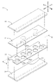
- FIG. 1 is a layout diagram of the skin material of the first embodiment.
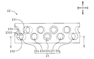
- 2 is an exploded perspective view within a frame II of FIG. 1.
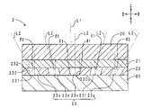
- FIG. 3 is a cross-sectional view taken along the line III-III of FIG.
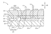
- FIG. 4 is a schematic diagram of a laser processing step in the manufacturing method of the skin material.
- FIG. 5 is a front-rear cross-sectional view of the skin material of the second embodiment.
- 6 is a surface view of the design layer of FIG. 5.
- FIG. FIG. 7 is a front-rear cross-sectional view of the skin material of the third embodiment.
- FIG. 8 is a front-rear cross-sectional view of the skin material of the fourth embodiment.
- FIG. 9A is a back view of the design layer of the skin material of another embodiment (No. 1).
- FIG. 9(B) is a back view of the design layer of the skin material of another embodiment (No. 2).
- FIG. 10 is a cross-sectional view in the front and back direction of the skin material of another embodiment (No. 3).
- FIG. 11 is a cross-sectional view of a conventional decorative sheet in the front and back direction.
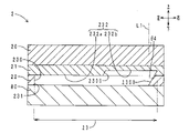
- FIG. 1 shows a layout diagram of the skin material of this embodiment.
- FIG. 2 shows an exploded perspective view within frame II of FIG.
- FIG. 3 shows a cross-sectional view along the III-III direction of FIG.
- FIG. 4 shows a schematic diagram of a laser processing step in the manufacturing method of the skin material. 3 and 4, the thickness in the front-back direction is emphasized.
- the skin material 2 is arranged on the entire surface (upper surface) of the console box (interior part) 90 of the passenger compartment.
- the skin material 2 includes a skin layer 20, an intermediate layer 21, a design layer 22, and a plurality of concave portions from the front side (inside the vehicle, upper side) to the back side (outer side, lower side). 23 and.
- the skin layer 20 is made of synthetic leather and has a layered shape.
- the skin layer 20 has translucency and flexibility.
- a textured pattern (not shown) is formed on the surface of the skin layer 20 .
- the intermediate layer 21 is laminated on the back surface (lower surface) of the skin layer 20 .
- the intermediate layer 21 is made of translucent ink and has a layered shape.
- the intermediate layer 21 has translucency and flexibility.
- the intermediate layer 21 has lower translucency than the skin layer 20 . That is, the intermediate layer 21 is smoky translucent. Further, the intermediate layer 21 is colored and transparent.
- the design layer 22 is laminated on the back surface of the intermediate layer 21 .
- the design layer 22 is made of opaque ink and has a layered shape.
- the design layer 22 has opacity and flexibility. That is, the design layer 22 does not transmit light.
- a plurality of recesses 23 are recessed in the back surface of the design layer 22 . Concave portion 23 will be described later in detail.
- a sheet-like light source 80 is arranged on the back side of the design layer 22 , that is, the back side of the skin material 2 .
- the light source 80 includes a plurality of LEDs (not shown). The surface of the light source 80 can emit light entirely.
- the plurality of recesses 23 are arranged over the entire back surface of the design layer 22, and as a whole form a polka dot design as shown in FIG.
- the concave portion 23 has a circular shape when viewed from the front and back directions.
- the internal space of the recess 23 has a cylindrical shape.
- the plurality of recesses 23 are classified into a plurality of reference recesses 23a and a plurality of deep recesses 23b.
- the reference recesses 23 a and the deep recesses 23 b are alternately arranged in the left-right direction (uniaxial direction) on the lower surface of the design layer 22 .
- the reference concave portion 23a includes a side surface (inner peripheral surface) 230, an opening portion 231, and a base portion 232a.
- the side surface 230 extends in the front-back direction.
- the side surface 230 has the shape of a straight pipe (specifically, the shape of the inner peripheral surface of a straight pipe).
- the side surface 230 extends parallel to the surface normal direction of the surface of the skin layer 20 .
- the opening 231 is arranged on the back surface of the design layer 22 .
- the base portion 232 a is arranged on the front side of the opening portion 231 .
- the deep recess 23b has a side surface (inner peripheral surface) 230 and an opening 231, like the reference recess 23a.
- the deep recess 23b has a deep bottom 232b instead of the base 232a.
- the deep bottom portion 232b is included in the concepts of "deep bottom portion" and "intermediate layer reaching portion” of the present invention.
- the only difference between the reference concave portion 23a and the deep concave portion 23b is the bottom portion 232 (base portion 232a, deep bottom portion 232b). Both the reference recess 23 a and the deep recess 23 b penetrate the design layer 22 . The reference recess 23 a does not reach the intermediate layer 21 . The base portion 232 a is arranged on the lower surface of the intermediate layer 21 . On the other hand, the deep recess 23b reaches the intermediate layer 21 . The deep bottom portion 232b is arranged in the middle of the intermediate layer 21 in the front-back direction.
- the manufacturing method of the skin material of this embodiment has a lamination process and a laser processing process.
- the lamination step the intermediate layer 21 and the design layer 22 are laminated on the back surface of the skin layer 20 by screen printing.
- the laminate is placed inside out (so that the back surface of the design layer 22 faces upward)
- a laser processing machine 91 is used to form recesses 23 (reference recesses 23 a and deep recesses 23 b ) on the back surface of the design layer 22 .
- a nozzle 910 of the laser processing machine 91 is relatively movable in the horizontal direction Y3 and the swing direction Y4 with respect to the laminate.
- a polka dot design consisting of a plurality of concave portions 23 is formed on the back surface of the design layer 22 .
- the depth of the recess 23 is adjusted by adjusting the laser output (power value). That is, the reference concave portion 23a and the deep concave portion 23b are separately formed.
- the skin material 2 is arranged on the front side of the light source 80 .
- the light source 80 When the light source 80 is on, the light source 80 emits light. For this reason, on the surface of the skin material 2, light transmitted through the plurality of reference recesses 23a, the intermediate layer 21 (the entire length of the thickness in the front-back direction), and the skin layer 20 (see arrow Y1 in FIG. 3), and a plurality of depths Light transmitted through the recesses 23b, the intermediate layer 21 (part of the thickness in the front-back direction), and the skin layer 20 (see arrow Y2 in FIG. 3) appears.
- the design of the design layer 22 (the polka dot pattern shown in FIG. 2) appears on the surface of the skin material 2 by these two types of light.
- the light transmitted through the deep recess 23b (arrow Y2) is brighter than the light transmitted through the reference recess 23a (arrow Y1). Therefore, on the surface of the skin material 2, two types of light and dark polka dot patterns emerge.
- the skin material 2 has a deep recess 23b, that is, a deep bottom 232b.
- the deep bottom 232b is arranged within the intermediate layer 21 layer. Therefore, the light transmittance can be reduced compared to the case where the bottoms 232 of the recesses 23 are uniformly the back surface of the skin layer 20 . On the contrary, the transmittance of light from the light source 80 can be improved compared to the case where the bottom 232 of the recess 23 is uniformly the back surface of the intermediate layer 21 . Further, when the deep bottom portion 232b is arranged closer to the skin layer 20, the deep recess portion 23b becomes deeper accordingly.
- the transmittance of light from the light source 80 can be improved.
- the deep bottom portion 232b is arranged closer to the design layer 22, the deep concave portion 23b becomes shallower accordingly. Therefore, the transmittance of light from the light source 80 can be reduced.
- the position of the deep bottom portion 232b in the front-back direction in this way, the design that appears on the surface of the upholstery material 2 can be adjusted. Therefore, the degree of design freedom is increased.
- the depth of the recess 23 differs between the base portion 232a and the deep bottom portion 232b. Due to the depth difference, a difference in light transmittance can be provided. Therefore, the design that appears on the surface of the skin material 2 can be adjusted. Therefore, the degree of design freedom is increased.
- the skin material 2 is provided with a translucent intermediate layer 21 . Therefore, when the light source 80 is off, the design of the design layer 22 can be suppressed from appearing on the surface of the skin material 2 . On the other hand, when the light source 80 is on, it can help the design of the design layer 22 to appear on the surface of the skin material 2 .
- the method for manufacturing the skin material 2 of the present embodiment has a lamination step and a laser processing step. According to the method for manufacturing the skin material 2 of the present embodiment, after the design layer 22 is printed on the back surface of the intermediate layer 21, the recesses 23 can be arranged in the design layer 22 by laser processing. Therefore, even if the design of the design layer 22 is changed, it is not necessary to change the screen mask one by one.
- the design of the design layer 22 can be changed simply by changing the movement of the nozzle 910 shown in FIG. 4 and the laser output. Therefore, the cost and downtime required for design change can be reduced. In addition, it is suitable for manufacturing a large variety of skin materials 2 in small quantities.
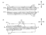
- ⁇ Second embodiment> A difference between the skin material of this embodiment and the skin material of the first embodiment is that the concave portion has an inclined portion. Only the points of difference are described here.
- FIG. 5 shows a front-back cross-sectional view of the skin material of this embodiment. Parts corresponding to those in FIG. 3 are denoted by the same reference numerals.
- the five recesses 23 are classified into one vertical recess 23c and four inclined recesses 23d to 23g.
- the bottoms 232 of the five recesses 23 (the vertical recesses 23c and the inclined recesses 23d to 23g) are arranged on the back surface of the intermediate layer 21, respectively.
- a side surface 230 of the recess 23 has an inclined portion 2300 .
- the vertical concave portion 23c extends in the vertical direction (front and back direction). That is, the axis L2 of the vertical concave portion 23c extends parallel to the direction in which the surface normal L1 of the surface of the skin layer 20 extends (front and back direction) (the inclination angle is 0°).
- An inclined portion 2300 of the vertical concave portion 23c has a tapered shape that tapers from the front side toward the back side at an inclination angle ⁇ 1.
- the inclined recess 23d to the left of the vertical recess 23c extends leftward from the opening 231 toward the bottom 232 (from the back side to the front side). That is, the axis L2 of the inclined recess 23d is inclined leftward by the inclination angle ⁇ 1 with respect to the extending direction of the surface normal L1.
- a side surface 230 of the inclined recess 23d has a straight tubular shape. Therefore, the inclined portion 2300 is inclined leftward by the inclination angle ⁇ 1, like the axis L2.
- the inclined recessed portion 23e on the left side of the inclined recessed portion 23d extends leftward from the opening portion 231 toward the bottom portion 232. That is, the axis L2 of the inclined recess 23e is inclined leftward with respect to the extending direction of the surface normal L1 by an inclination angle ⁇ 2 (> ⁇ 1).
- a side surface 230 of the inclined recess 23e has a straight tubular shape. Therefore, the inclined portion 2300 is inclined leftward by an inclination angle ⁇ 2, like the axis L2.
- the inclined recessed portion 23f on the right side of the vertical recessed portion 23c extends rightward from the opening portion 231 toward the bottom portion 232 at an inclination angle ⁇ 1.
- Other configurations are the same as those of the inclined recess 23d.
- the inclined recessed portion 23g on the right side of the inclined recessed portion 23f extends rightward from the opening portion 231 toward the bottom portion 232 at an inclination angle ⁇ 2.
- Other configurations are the same as those of the inclined recess 23e.
- Fig. 6 shows a surface view of the design layer in Fig. 5.
- the design layer in FIG. 5 corresponds to the cross-sectional view taken along the line VV in FIG.
- the outer peripheral edges of the bottoms 232 of the five recesses 23 (the vertical recesses 23c and the inclined recesses 23d to 23g) and the outer peripheral edges of the openings 231 do not match. That is, when seen through from the front side, the outer peripheral edges of the bottoms 232 of the five recesses 23 and the outer peripheral edges of the openings 231 are arranged so as to be offset from each other.
- the skin material of the present embodiment and the skin material of the first embodiment have the same action and effect with respect to the portions having the common configurations.
- side surfaces 230 of a plurality of recesses 23 each have an inclined portion 2300.
- the inclined portion 2300 extends in a direction crossing the extending direction of the surface normal L1. Therefore, when the light traveling in the direction of the surface normal L ⁇ b>1 in the concave portion 23 is incident on the inclined portion 2300 , at least part of the light may be reflected by the inclined portion 2300 . Also, the light may be refracted by the inclined portion 2300 . Therefore, the design that appears on the surface of the skin material 2 can be adjusted. Therefore, the degree of design freedom is increased.
- the inclination directions of the plurality of concave portions 23 are different from each other. In this respect as well, the design that appears on the surface of the skin material 2 can be adjusted. In addition, a plurality of inclination angles (0°, ⁇ 1, ⁇ 2) are set for the inclined portions 2300 of the plurality of concave portions 23 . In this respect as well, the design that appears on the surface of the skin material 2 can be adjusted.
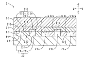
- ⁇ Third embodiment> The difference between the skin material of this embodiment and the skin materials of the first and second embodiments is that the concave portion has an intermediate layer reaching portion, a base portion, a deep bottom portion, and an inclined portion. Another difference is that the intermediate layer has a two-layer structure. Only the points of difference are described here.
- FIG. 7 shows a front-back cross-sectional view of the skin material of this embodiment. Parts corresponding to those in FIGS. 3 and 5 are denoted by the same reference numerals.
- the intermediate layer 21 includes a surface layer (first layer) 210 and a back layer (second layer) 211 . Each of the surface layer 210 and the back layer 211 has translucency.
- the back layer 211 has a lower translucency than the surface layer 210 . Also, the back layer 211 and the surface layer 210 have different colors.
- the recess 23l on the right end corresponds to the reference recess 23a in FIG.
- the remaining four recesses 23h-23k correspond to the deep recess 23b in FIG. That is, the bottom portion (specifically, the front side edge of the bottom portion; the same applies hereinafter) 232l of the concave portion 23l is included in the concept of the "base portion" of the present invention. Further, the bottoms 232h-232k of the recesses 23h-23k are included in the concepts of "deep bottom” and "intermediate layer reaching portion” of the present invention. The bottoms 232 h - 232 k are arranged within layers of the intermediate layer 21 .
- the five recesses 23h to 23l correspond to the inclined recesses 23d to 23g in FIG. That is, the side surfaces 230 of the five recesses 23h to 23l each have an inclined portion 2300. As shown in FIG. The axes L2 of the five concave portions 23h to 23l are inclined rightward by an inclination angle ⁇ 3 with respect to the extending direction of the surface normal L1. Side surfaces 230 of the five recesses 23h to 23l each have a straight tubular shape. Therefore, the five inclined portions 2300 are inclined rightward by the inclination angle ⁇ 3, like the axis L2.
- a plurality of inclined portions 2300 may be inclined in the same direction as in this embodiment. In this way, the design appearing on the surface of the upholstery material 2 can have directivity (the characteristic that the design is easily visible from a predetermined direction (for example, the driver's seat side and the passenger's seat side)). Also, the plurality of inclined portions 2300 may be inclined at the same inclination angle ⁇ 3. In this way, the degrees of reflection and refraction of light can be made uniform in the plurality of inclined portions 2300 . Therefore, the design appearing on the surface of the skin material 2 can be made uniform.
- the depths of the plurality of recesses 23h to 23l may all be different.
- the base portion 232l of the concave portion 23l may be arranged within the design layer 22 .
- the intermediate layer 21 may be composed of a plurality of layers (the surface layer 210 and the back layer 211).
- the intermediate layer 21 may be composed of a plurality of layers, and the translucency of each layer may be gradually decreased from the front side to the back side.
- the intermediate layer 21 may be composed of a plurality of layers, and each layer may have a different color.
- the design layer 22 when the design layer 22 has translucency, the design layer 22 may be composed of a plurality of layers, and the translucency of each layer may be gradually reduced from the front side to the back side. Moreover, the design layer 22 may be composed of a plurality of layers, and each layer may have a different color.
- ⁇ Fourth embodiment> The difference between the skin material of this embodiment and the skin material of the third embodiment is that a single concave portion has an intermediate layer reaching portion, a base portion, a deep bottom portion, and an inclined portion. Another difference is that the intermediate layer has a single-layer structure. Only the points of difference are described here.
- FIG. 8 shows a front-back cross-sectional view of the skin material of this embodiment. Parts corresponding to those in FIGS. 3 and 5 are denoted by the same reference numerals.
- the bottom portion 232 of the recess 23 has a base portion 232a and a deep bottom portion 232b.
- the deep bottom portion 232b is included in the concepts of "deep bottom portion” and "intermediate layer reaching portion” of the present invention.
- An inclined portion 2300 is arranged in a portion of the side surface 230 of the recess 23 that continues to the deep bottom portion 232b.
- the inclined portion 2300 is inclined rightward by an inclination angle ⁇ 4 with respect to the extending direction of the surface normal L1.
- a single concave portion 23 may include a base portion 232a, a deep bottom portion (intermediate layer reaching portion) 232b, and an inclined portion 2300 as in this embodiment.
- FIG. 9A shows a back view of the design layer of the skin material of another embodiment (No. 1).
- FIG. 9B shows a back view of the design layer of the skin material of another embodiment (No. 2). Parts corresponding to those in FIG. 3 are denoted by the same reference numerals. Moreover, hatching is applied to the concave portion.
- each of the two recesses 23m and 23n has a strip shape extending in the left-right direction.
- 23 m of recessed parts are included in the concept of the "wide part" of this invention.
- the concave portion 23n is included in the concept of the "basal width portion” of the present invention.
- the recess 23m has an opening width (specifically, the width in the front-rear direction of the opening 231 (the width in the direction orthogonal to the extending direction of the recesses 23m and 23n; the width in the lateral direction)) D that is wider than the recess 23n.
- the concave portion 23 has a strip shape extending in the left-right direction.
- the left portion 23o of the recess 23 is included in the concept of the "wide portion” of the present invention.
- the right portion 23p is included in the concept of the "basal portion” of the present invention.
- the left portion 23o has a wider opening width D than the right portion 23p.
- FIGS. 9A and 9B by arranging portions (base width portion and wide width portion) having different opening widths D in the recess 23, the design that appears on the surface of the upholstery material 2 can be adjusted. be able to. Therefore, the degree of design freedom is increased. 9(A) and 9(B) can be incorporated into the recesses 23 shown in FIGS. 3, 5, 7 and 8. FIG.
- FIG. 10 shows a cross-sectional view of the surface material of another embodiment (No. 3) in the front and back direction. Parts corresponding to those in FIG. 3 are denoted by the same reference numerals.
- the intermediate layer 21 includes a left layer (first layer) 212 and a right layer (second layer) 213 . Each of the left layer 212 and the right layer 213 has translucency. The left layer 212 and the right layer 213 are different in color and translucency.
- the design layer 22 includes a left layer (first layer) 222 and a right layer (second layer) 223 . Each of the left layer 222 and the right layer 223 is opaque. The left layer 222 and the right layer 223 have different colors. As shown in FIG.
- At least one of the intermediate layer 21 and the design layer 22 may have a plurality of layers arranged in the surface direction (direction orthogonal to the front-back direction). By doing so, the design that appears on the surface of the skin material 2 can be adjusted. Therefore, the degree of design freedom is increased.
- the positions of the base portions 232a, 232l and the deep bottom portions 232b, 232h to 232k shown in FIGS. 3, 7 and 8 are not particularly limited. It may be inside the design layer 22 (when the design layer 22 is translucent), on the back surface of the intermediate layer 21, inside the intermediate layer 21, or the like.
- the inclination angle and extending direction (inclination direction) of the inclined portion 2300 shown in FIGS. 5, 7, and 8 are not particularly limited.
- the design that appears on the skin material 2 by the recesses 23 is not particularly limited. For example, patterns (polka dots, striped patterns, lattice patterns, heathered patterns, marble patterns, etc.), characters (alphabet, hiragana, katakana, kanji, numbers, etc.), figures (polygons, circles, etc.), symbols (for device operation) buttons, icons indicating device status, etc.).
- the color of the design appearing on the skin material 2 may be monochromatic or multicolored. The color may be displayed on the skin material 2 by one or more selected from the skin layer 20 , the intermediate layer 21 , the design layer 22 and the light source 80 . In particular, if a portion overlapping with the concave portion 23 when viewed from the front side is colored, the light from the light source 80 tends to cause the skin material 2 to develop a color.
- the translucency of the skin layer 20 and intermediate layer 21 is not particularly limited. It may be colorless and transparent, colored and transparent, translucent, and the like.
- the intermediate layer 21 may have a gradation in which the color changes from the back surface to the front surface. In this way, the color that appears on the surface of the upholstery material 2 can be changed according to the positions of the intermediate layer reaching portions (the deep bottom portion 232b in FIGS. 3 and 8 and the bottom portions 232h to 232k in FIG. 7).
- the gradation of the intermediate layer 21 may be formed by a plurality of layers.
- the design layer 22 does not have to be opaque. In other words, the design layer 22 should have a lower translucency than the intermediate layer 21 .
- the design layer 22 may have a gradation in which the color changes from the back surface to the front surface. By doing so, the color that appears on the surface of the upholstery material 2 can be changed according to the position of the bottom portion (the base portion 232l in FIG. 7).
- the colors (hue, saturation, brightness) of the skin layer 20, the intermediate layer 21, the design layer 22, and the light source 80 are not particularly limited. Also, the brightness of the light source 80 is not particularly limited.
- a translucent sensor for example, a capacitive sensor
- the skin material 2 can be used as a sensor or a switch.
- the timing at which the light source 80 is turned on is not particularly limited. It may be always on. Also, the light source 80 may be turned on in conjunction with the room lamp, headlight, or the like of the vehicle. Alternatively, the light source 80 may be turned on when a proximity sensor (for example, a capacitive sensor) detects the proximity of the user to the upholstery 2 .
- a proximity sensor for example, a capacitive sensor
- the type of light source 80 is not particularly limited. It may be an organic EL sheet or an inorganic EL sheet. Also, the light source 80 may include a light source main body (for example, an LED) and a light guide plate (for example, an acrylic plate). In this case, the light source body may be arranged next to the light guide plate in the surface direction, the surface of the light guide plate may be surface-emitting, and the skin material 2 may be arranged on the front side of the light guide plate.
- the light source 80 may be a phosphorescent sheet.
- the interior parts on which the skin material 2 is arranged are not particularly limited. Examples include door trims, seats, floors, ceilings, instrument panels, center clusters, glove compartments, steering wheels (handles), center consoles, and registers.
- the surface on which the skin material 2 is installed in the interior member may be flat or curved.
- the orientation (orientation in the front/back direction) when arranging the skin material 2 is not particularly limited.
- the skin material 2 may be arranged on interior parts of ships, aircraft, buildings, and houses other than vehicles.
- the configuration of the skin material 2 is not particularly limited. Of the skin layer 20, the intermediate layer 21, the design layer 22, and the light source 80, two layers adjacent in the front and back direction (between the skin layer 20 and the intermediate layer 21, between the intermediate layer 21 and the design layer 22, and the design layer 22) and the light source 80), other layers may be interposed. Further, another layer may be arranged on the front side of the skin layer 20 .
- the material of the skin layer 20 is not particularly limited. Examples include synthetic leather, resins, elastomers, nonwoven fabrics, and various types of cloth (woven fabrics, knitted fabrics, etc.). Synthetic leather, resins, and elastomers include acrylic, polyethylene terephthalate, polycarbonate, polyvinyl chloride, silicone, epoxy, polyurethane, styrenic thermoplastic elastomers, olefinic thermoplastic elastomers, dynamic cross-linking thermoplastic elastomers, and the like. is mentioned. Examples of nonwoven fabrics and various fabrics include polyester, polypropylene, nylon, and cotton.
- the skin layer 20 may contain colored particles such as colored polyethylene particles, light diffusing particles such as titanium oxide, and light absorbing particles such as titanium black and carbon black.
- the visible light transmittance of the skin layer 20 is preferably 50% or more and 100% or less. This makes it possible to make the design of the design layer 22 stand out more on the surface of the skin material 2 when the light source 80 is turned on.
- the visible light transmittance is a value calculated by measuring the transmission spectrum at a wavelength of 380 to 780 nm with a spectrophotometer "UV3100PC" manufactured by Shimadzu Corporation in accordance with JIS A5759:2016. adopt.
- the material of the intermediate layer 21 is not particularly limited. Examples include resins and elastomers such as acrylic, polyethylene terephthalate, polycarbonate, polyvinyl chloride, silicone, polyester, epoxy, polyurethane, styrene-based thermoplastic elastomer, olefin-based thermoplastic elastomer, and dynamic cross-linking thermoplastic elastomer. .
- the intermediate layer 21 may contain colored particles such as colored polyethylene particles, light diffusing particles such as titanium oxide, and light absorbing particles such as titanium black and carbon black.
- the visible light transmittance of the intermediate layer 21 is preferably more than 0% and 40% or less. This makes the design of the design layer 22 less noticeable when the light source 80 is off.
- the material of the design layer 22 is not particularly limited. Examples include resins and elastomers such as acrylic, polyethylene terephthalate, polycarbonate, polyvinyl chloride, silicone, polyester, epoxy, polyurethane, styrene-based thermoplastic elastomer, olefin-based thermoplastic elastomer, and dynamic cross-linking thermoplastic elastomer. .
- the design layer 22 may contain colored particles such as colored polyethylene particles, light diffusing particles such as titanium oxide, and light absorbing particles such as titanium black and carbon black.
- the method of laminating the skin layer 20, the intermediate layer 21, and the design layer 22 is not particularly limited. In addition to screen printing, gravure printing, inkjet printing, flexographic printing, and the like may be used. Moreover, each layer may be laminated by adhesion, vapor deposition, or the like. A method for forming the concave portion 23 is not particularly limited. In addition to laser processing, photoetching or the like may be used.
Landscapes
- Chemical & Material Sciences (AREA)
- Engineering & Computer Science (AREA)
- Physics & Mathematics (AREA)
- Optics & Photonics (AREA)
- Medicinal Chemistry (AREA)
- Organic Chemistry (AREA)
- Polymers & Plastics (AREA)
- Health & Medical Sciences (AREA)
- Chemical Kinetics & Catalysis (AREA)
- Plasma & Fusion (AREA)
- Mechanical Engineering (AREA)
- General Chemical & Material Sciences (AREA)
- Laminated Bodies (AREA)
- Laser Beam Processing (AREA)
Priority Applications (2)
| Application Number | Priority Date | Filing Date | Title |
|---|---|---|---|
| CN202280019307.9A CN116917116A (zh) | 2021-03-31 | 2022-03-30 | 表皮材料 |
| US18/462,430 US20230407027A1 (en) | 2021-03-31 | 2023-09-07 | Skin material |
Applications Claiming Priority (2)
| Application Number | Priority Date | Filing Date | Title |
|---|---|---|---|
| JP2021-062358 | 2021-03-31 | ||
| JP2021062358A JP7777927B2 (ja) | 2021-03-31 | 2021-03-31 | 表皮材 |
Related Child Applications (1)
| Application Number | Title | Priority Date | Filing Date |
|---|---|---|---|
| US18/462,430 Continuation US20230407027A1 (en) | 2021-03-31 | 2023-09-07 | Skin material |
Publications (1)
| Publication Number | Publication Date |
|---|---|
| WO2022210986A1 true WO2022210986A1 (ja) | 2022-10-06 |
Family
ID=83459610
Family Applications (1)
| Application Number | Title | Priority Date | Filing Date |
|---|---|---|---|
| PCT/JP2022/016323 Ceased WO2022210986A1 (ja) | 2021-03-31 | 2022-03-30 | 表皮材 |
Country Status (4)
| Country | Link |
|---|---|
| US (1) | US20230407027A1 (enExample) |
| JP (1) | JP7777927B2 (enExample) |
| CN (1) | CN116917116A (enExample) |
| WO (1) | WO2022210986A1 (enExample) |
Cited By (3)
| Publication number | Priority date | Publication date | Assignee | Title |
|---|---|---|---|---|
| WO2025142408A1 (ja) * | 2023-12-28 | 2025-07-03 | 東海化成工業株式会社 | 加飾シート |
| WO2025142409A1 (ja) * | 2023-12-28 | 2025-07-03 | 東海化成工業株式会社 | 積層部材製造方法 |
| WO2025142407A1 (ja) * | 2023-12-28 | 2025-07-03 | 東海化成工業株式会社 | 加飾シートおよびその製造方法 |
Citations (3)
| Publication number | Priority date | Publication date | Assignee | Title |
|---|---|---|---|---|
| JP2018163341A (ja) * | 2017-03-24 | 2018-10-18 | 大日本印刷株式会社 | 加飾シート、及び透過型投射システム |
| JP2020101781A (ja) * | 2018-12-20 | 2020-07-02 | パナソニックIpマネジメント株式会社 | 照明装置 |
| JP2020163834A (ja) * | 2019-03-28 | 2020-10-08 | 大日本印刷株式会社 | 加飾シートの製造方法、加飾シート及び加飾シート付き表示装置 |
Family Cites Families (4)
| Publication number | Priority date | Publication date | Assignee | Title |
|---|---|---|---|---|
| WO2008013097A1 (en) * | 2006-07-25 | 2008-01-31 | Showa Denko K.K. | Light emitting apparatus, display apparatus and method for manufacturing light emitting apparatus |
| DE102008054721B3 (de) * | 2008-12-16 | 2010-04-15 | Lisa Dräxlmaier GmbH | Lichtstreuender Dekorverbund, Verfahren zu seiner Herstellung sowie seine Verwendung für eine Interieurkomponente für ein Fahrzeug |
| AT517576B1 (de) * | 2015-11-27 | 2017-03-15 | Hornschuch Ag K | Verfahren zur Herstellung eines Verbundmaterials und Verbundmaterial |
| JP2021022448A (ja) * | 2019-07-25 | 2021-02-18 | パナソニックIpマネジメント株式会社 | 照明装置 |
-
2021
- 2021-03-31 JP JP2021062358A patent/JP7777927B2/ja active Active
-
2022
- 2022-03-30 CN CN202280019307.9A patent/CN116917116A/zh active Pending
- 2022-03-30 WO PCT/JP2022/016323 patent/WO2022210986A1/ja not_active Ceased
-
2023
- 2023-09-07 US US18/462,430 patent/US20230407027A1/en active Pending
Patent Citations (3)
| Publication number | Priority date | Publication date | Assignee | Title |
|---|---|---|---|---|
| JP2018163341A (ja) * | 2017-03-24 | 2018-10-18 | 大日本印刷株式会社 | 加飾シート、及び透過型投射システム |
| JP2020101781A (ja) * | 2018-12-20 | 2020-07-02 | パナソニックIpマネジメント株式会社 | 照明装置 |
| JP2020163834A (ja) * | 2019-03-28 | 2020-10-08 | 大日本印刷株式会社 | 加飾シートの製造方法、加飾シート及び加飾シート付き表示装置 |
Cited By (3)
| Publication number | Priority date | Publication date | Assignee | Title |
|---|---|---|---|---|
| WO2025142408A1 (ja) * | 2023-12-28 | 2025-07-03 | 東海化成工業株式会社 | 加飾シート |
| WO2025142409A1 (ja) * | 2023-12-28 | 2025-07-03 | 東海化成工業株式会社 | 積層部材製造方法 |
| WO2025142407A1 (ja) * | 2023-12-28 | 2025-07-03 | 東海化成工業株式会社 | 加飾シートおよびその製造方法 |
Also Published As
| Publication number | Publication date |
|---|---|
| JP7777927B2 (ja) | 2025-12-01 |
| US20230407027A1 (en) | 2023-12-21 |
| CN116917116A (zh) | 2023-10-20 |
| JP2022157880A (ja) | 2022-10-14 |
Similar Documents
| Publication | Publication Date | Title |
|---|---|---|
| US20230407027A1 (en) | Skin material | |
| JP7731311B2 (ja) | 加飾シートおよび内装部材 | |
| JP2017154581A (ja) | 車両用透光部材、車両用加飾装置および車両用加飾方法 | |
| JP6497424B2 (ja) | 車両の車室内構造 | |
| JP7117636B2 (ja) | 照明装置 | |
| US11958416B2 (en) | Display panel | |
| JP2016110775A (ja) | 車両用スイッチ装置 | |
| EP2428408B1 (en) | Vehicle upholstery member | |
| US20240181882A1 (en) | Component for vehicle interior | |
| JP2020157956A (ja) | ステアリングホイール | |
| JP2025069439A (ja) | センサアセンブリおよびその製造方法 | |
| JP7543993B2 (ja) | 乗物用スイッチ装置 | |
| JP7711024B2 (ja) | 内装部材 | |
| WO2025142407A1 (ja) | 加飾シートおよびその製造方法 | |
| KR102384653B1 (ko) | 차량용 발광 내장재 | |
| JP2021022448A (ja) | 照明装置 | |
| KR20080070000A (ko) | 표시 장치 | |
| JP2024065138A (ja) | 内装部材 | |
| TW202246084A (zh) | 包含整合顯示區域之裝飾元件 | |
| WO2025142408A1 (ja) | 加飾シート | |
| JP2018025509A (ja) | 車両表示装置 | |
| JP6350332B2 (ja) | 内装部品 | |
| JP2025097415A (ja) | 表示パネルおよびそれを備えた表示灯装置、ならびに表示パネルの製造方法 | |
| WO2025142409A1 (ja) | 積層部材製造方法 | |
| JP2025121045A (ja) | 表皮材および内装部材 |
Legal Events
| Date | Code | Title | Description |
|---|---|---|---|
| 121 | Ep: the epo has been informed by wipo that ep was designated in this application |
Ref document number: 22781196 Country of ref document: EP Kind code of ref document: A1 |
|
| WWE | Wipo information: entry into national phase |
Ref document number: 202280019307.9 Country of ref document: CN |
|
| NENP | Non-entry into the national phase |
Ref country code: DE |
|
| 122 | Ep: pct application non-entry in european phase |
Ref document number: 22781196 Country of ref document: EP Kind code of ref document: A1 |