WO2022210912A1 - アンモニアの製造方法及び製造装置 - Google Patents
アンモニアの製造方法及び製造装置 Download PDFInfo
- Publication number
- WO2022210912A1 WO2022210912A1 PCT/JP2022/016089 JP2022016089W WO2022210912A1 WO 2022210912 A1 WO2022210912 A1 WO 2022210912A1 JP 2022016089 W JP2022016089 W JP 2022016089W WO 2022210912 A1 WO2022210912 A1 WO 2022210912A1
- Authority
- WO
- WIPO (PCT)
- Prior art keywords
- cathode
- molybdenum complex
- group
- catalyst
- atom
- Prior art date
- Legal status (The legal status is an assumption and is not a legal conclusion. Google has not performed a legal analysis and makes no representation as to the accuracy of the status listed.)
- Ceased
Links
Images


Classifications
-
- C—CHEMISTRY; METALLURGY
- C25—ELECTROLYTIC OR ELECTROPHORETIC PROCESSES; APPARATUS THEREFOR
- C25B—ELECTROLYTIC OR ELECTROPHORETIC PROCESSES FOR THE PRODUCTION OF COMPOUNDS OR NON-METALS; APPARATUS THEREFOR
- C25B1/00—Electrolytic production of inorganic compounds or non-metals
- C25B1/01—Products
- C25B1/27—Ammonia
-
- B—PERFORMING OPERATIONS; TRANSPORTING
- B01—PHYSICAL OR CHEMICAL PROCESSES OR APPARATUS IN GENERAL
- B01J—CHEMICAL OR PHYSICAL PROCESSES, e.g. CATALYSIS OR COLLOID CHEMISTRY; THEIR RELEVANT APPARATUS
- B01J31/00—Catalysts comprising hydrides, coordination complexes or organic compounds
- B01J31/16—Catalysts comprising hydrides, coordination complexes or organic compounds containing coordination complexes
- B01J31/22—Organic complexes
-
- C—CHEMISTRY; METALLURGY
- C07—ORGANIC CHEMISTRY
- C07F—ACYCLIC, CARBOCYCLIC OR HETEROCYCLIC COMPOUNDS CONTAINING ELEMENTS OTHER THAN CARBON, HYDROGEN, HALOGEN, OXYGEN, NITROGEN, SULFUR, SELENIUM OR TELLURIUM
- C07F11/00—Compounds containing elements of Groups 6 or 16 of the Periodic Table
-
- C—CHEMISTRY; METALLURGY
- C07—ORGANIC CHEMISTRY
- C07F—ACYCLIC, CARBOCYCLIC OR HETEROCYCLIC COMPOUNDS CONTAINING ELEMENTS OTHER THAN CARBON, HYDROGEN, HALOGEN, OXYGEN, NITROGEN, SULFUR, SELENIUM OR TELLURIUM
- C07F11/00—Compounds containing elements of Groups 6 or 16 of the Periodic Table
- C07F11/005—Compounds containing elements of Groups 6 or 16 of the Periodic Table compounds without a metal-carbon linkage
-
- C—CHEMISTRY; METALLURGY
- C25—ELECTROLYTIC OR ELECTROPHORETIC PROCESSES; APPARATUS THEREFOR
- C25B—ELECTROLYTIC OR ELECTROPHORETIC PROCESSES FOR THE PRODUCTION OF COMPOUNDS OR NON-METALS; APPARATUS THEREFOR
- C25B11/00—Electrodes; Manufacture thereof not otherwise provided for
- C25B11/02—Electrodes; Manufacture thereof not otherwise provided for characterised by shape or form
- C25B11/03—Electrodes; Manufacture thereof not otherwise provided for characterised by shape or form perforated or foraminous
- C25B11/031—Porous electrodes
- C25B11/032—Gas diffusion electrodes
-
- C—CHEMISTRY; METALLURGY
- C25—ELECTROLYTIC OR ELECTROPHORETIC PROCESSES; APPARATUS THEREFOR
- C25B—ELECTROLYTIC OR ELECTROPHORETIC PROCESSES FOR THE PRODUCTION OF COMPOUNDS OR NON-METALS; APPARATUS THEREFOR
- C25B11/00—Electrodes; Manufacture thereof not otherwise provided for
- C25B11/04—Electrodes; Manufacture thereof not otherwise provided for characterised by the material
- C25B11/051—Electrodes formed of electrocatalysts on a substrate or carrier
- C25B11/052—Electrodes comprising one or more electrocatalytic coatings on a substrate
-
- C—CHEMISTRY; METALLURGY
- C25—ELECTROLYTIC OR ELECTROPHORETIC PROCESSES; APPARATUS THEREFOR
- C25B—ELECTROLYTIC OR ELECTROPHORETIC PROCESSES FOR THE PRODUCTION OF COMPOUNDS OR NON-METALS; APPARATUS THEREFOR
- C25B11/00—Electrodes; Manufacture thereof not otherwise provided for
- C25B11/04—Electrodes; Manufacture thereof not otherwise provided for characterised by the material
- C25B11/051—Electrodes formed of electrocatalysts on a substrate or carrier
- C25B11/054—Electrodes comprising electrocatalysts supported on a carrier
-
- C—CHEMISTRY; METALLURGY
- C25—ELECTROLYTIC OR ELECTROPHORETIC PROCESSES; APPARATUS THEREFOR
- C25B—ELECTROLYTIC OR ELECTROPHORETIC PROCESSES FOR THE PRODUCTION OF COMPOUNDS OR NON-METALS; APPARATUS THEREFOR
- C25B11/00—Electrodes; Manufacture thereof not otherwise provided for
- C25B11/04—Electrodes; Manufacture thereof not otherwise provided for characterised by the material
- C25B11/051—Electrodes formed of electrocatalysts on a substrate or carrier
- C25B11/073—Electrodes formed of electrocatalysts on a substrate or carrier characterised by the electrocatalyst material
- C25B11/075—Electrodes formed of electrocatalysts on a substrate or carrier characterised by the electrocatalyst material consisting of a single catalytic element or catalytic compound
-
- C—CHEMISTRY; METALLURGY
- C25—ELECTROLYTIC OR ELECTROPHORETIC PROCESSES; APPARATUS THEREFOR
- C25B—ELECTROLYTIC OR ELECTROPHORETIC PROCESSES FOR THE PRODUCTION OF COMPOUNDS OR NON-METALS; APPARATUS THEREFOR
- C25B11/00—Electrodes; Manufacture thereof not otherwise provided for
- C25B11/04—Electrodes; Manufacture thereof not otherwise provided for characterised by the material
- C25B11/051—Electrodes formed of electrocatalysts on a substrate or carrier
- C25B11/073—Electrodes formed of electrocatalysts on a substrate or carrier characterised by the electrocatalyst material
- C25B11/091—Electrodes formed of electrocatalysts on a substrate or carrier characterised by the electrocatalyst material consisting of at least one catalytic element and at least one catalytic compound; consisting of two or more catalytic elements or catalytic compounds
- C25B11/095—Electrodes formed of electrocatalysts on a substrate or carrier characterised by the electrocatalyst material consisting of at least one catalytic element and at least one catalytic compound; consisting of two or more catalytic elements or catalytic compounds at least one of the compounds being organic
-
- C—CHEMISTRY; METALLURGY
- C25—ELECTROLYTIC OR ELECTROPHORETIC PROCESSES; APPARATUS THEREFOR
- C25B—ELECTROLYTIC OR ELECTROPHORETIC PROCESSES FOR THE PRODUCTION OF COMPOUNDS OR NON-METALS; APPARATUS THEREFOR
- C25B9/00—Cells or assemblies of cells; Constructional parts of cells; Assemblies of constructional parts, e.g. electrode-diaphragm assemblies; Process-related cell features
-
- C—CHEMISTRY; METALLURGY
- C25—ELECTROLYTIC OR ELECTROPHORETIC PROCESSES; APPARATUS THEREFOR
- C25B—ELECTROLYTIC OR ELECTROPHORETIC PROCESSES FOR THE PRODUCTION OF COMPOUNDS OR NON-METALS; APPARATUS THEREFOR
- C25B9/00—Cells or assemblies of cells; Constructional parts of cells; Assemblies of constructional parts, e.g. electrode-diaphragm assemblies; Process-related cell features
- C25B9/17—Cells comprising dimensionally-stable non-movable electrodes; Assemblies of constructional parts thereof
- C25B9/19—Cells comprising dimensionally-stable non-movable electrodes; Assemblies of constructional parts thereof with diaphragms
- C25B9/23—Cells comprising dimensionally-stable non-movable electrodes; Assemblies of constructional parts thereof with diaphragms comprising ion-exchange membranes in or on which electrode material is embedded
-
- Y—GENERAL TAGGING OF NEW TECHNOLOGICAL DEVELOPMENTS; GENERAL TAGGING OF CROSS-SECTIONAL TECHNOLOGIES SPANNING OVER SEVERAL SECTIONS OF THE IPC; TECHNICAL SUBJECTS COVERED BY FORMER USPC CROSS-REFERENCE ART COLLECTIONS [XRACs] AND DIGESTS
- Y02—TECHNOLOGIES OR APPLICATIONS FOR MITIGATION OR ADAPTATION AGAINST CLIMATE CHANGE
- Y02P—CLIMATE CHANGE MITIGATION TECHNOLOGIES IN THE PRODUCTION OR PROCESSING OF GOODS
- Y02P20/00—Technologies relating to chemical industry
- Y02P20/50—Improvements relating to the production of bulk chemicals
- Y02P20/52—Improvements relating to the production of bulk chemicals using catalysts, e.g. selective catalysts
Definitions
- the present invention relates to a method and apparatus for producing ammonia.
- Non-Patent Document 1 In the method of producing ammonia from nitrogen molecules by electrolysis in a low temperature range, there is a reported example of electrolytic production of ammonia at 90 ° C. using a platinum electrode as an anode and a cathode in which ruthenium is supported on carbon felt.
- Non-Patent Document 2 There is a reported example of producing ammonia by electrolysis using Sm 1.5 Sr 0.5 CoO 4 or the like as an ammonia generating electrode.
- Non-Patent Documents 3 samarium (II) iodide as a reducing agent and alcohols or water as a proton source. It has been reported that ammonia was produced using a molybdenum complex supported on polystyrene resin (Non-Patent Document 4).
- Non-Patent Document 1 operates at a low temperature range of around 90 to 100°C, so the problem was the operation at room temperature around 20 to 30°C.
- Non-Patent Document 2 has a problem that it is not easy from the viewpoint of reuse of the electrolytic device because there is a complicated process of treating the membrane with ammonia before incorporating the Nafion membrane used as the electrolyte membrane into the electrolytic device.
- Non-Patent Document 3 requires the use of samarium (II) iodide as the reducing agent
- Non-Patent Document 4 requires the use of decamethylcobaltocene as the reducing agent. Since it is 3 equivalents to 1 equivalent, from the viewpoint of practical use, the problem is that recovery and recycling of these reducing agents are not easy.
- the present invention has been made to solve the above-mentioned problems, and does not use a reducing agent, avoids the pretreatment of the electrolyte membrane, and operates at room temperature, around 20 to 30°C.
- the main purpose is a method for manufacturing
- Non-Patent Documents 1 and 2 are reported examples of electrochemical ammonia production using a solid catalyst, and electrochemically using a membrane electrode assembly or a gas diffusion electrode prepared by combining a complex and a solid catalyst. There are no reported cases of ammonia production.
- the present invention based on these findings is, for example, as follows. [1] Providing electrons from a power supply, protons from a proton source, and nitrogen molecules from a means for supplying nitrogen gas in the presence of a complex, a solid catalyst, and a reaction field forming material at a cathode in a manufacturing apparatus that performs electrolysis.
- a method for producing ammonia from nitrogen molecules by The complex is (A) 2,6-bis(dialkylphosphinomethyl)pyridine as a PNP ligand (provided that the two alkyl groups may be the same or different, and at least one hydrogen atom of the pyridine ring is an alkyl group, an alkoxy group or a molybdenum complex having a halogen atom), (B) N,N-bis(dialkylphosphinomethyl)dihydrobenzimidazolidene as a PCP ligand (provided that the two alkyl groups may be the same or different, and at least one hydrogen atom of the benzene ring is an alkyl group , optionally substituted by an alkoxy group or a halogen atom), a molybdenum complex having (C) a molybdenum complex having a bis(dialkylphosphinoethyl)arylphosphine (wherein the two alkyl groups may be the same
- the molybdenum complex (A) has the following formula (A1), (A2) or (A3) (wherein R 1 and R 2 are alkyl groups that may be the same or different, X is an iodine atom, a bromine atom or a chlorine atom, and at least one hydrogen atom on the pyridine ring is an alkyl group , optionally substituted with an alkoxy group or a halogen atom), the method for producing ammonia according to [1].
- the molybdenum complex (B) is represented by the following formula (B1) or (B2) (Wherein, R 1 and R 2 are alkyl groups that may be the same or different, X is an iodine atom, a bromine atom or a chlorine atom, and at least one hydrogen atom on the benzene ring is an alkyl group , may be substituted with an alkoxy group or a halogen atom, and at least one of R 3 and R 4 is substituted with a trifluoromethyl group). Production method.
- the molybdenum complex (C) has the formula (C1) (wherein R 1 and R 2 are alkyl groups which may be the same or different, R 5 is an aryl group, and X is an iodine atom, a bromine atom or a chlorine atom)
- the molybdenum complex (D) has the formula (D1) or (D2) (Wherein, R 5 and R 6 are aryl groups that may be the same or different, R 7 is an alkyl group, and n is 2 or 3) is a molybdenum complex represented by The method for producing ammonia according to [1].
- the anode catalyst layer comprises an anode solid catalyst,
- the complex is (A) 2,6-bis(dialkylphosphinomethyl)pyridine as a PNP ligand (provided that the two alkyl groups may be the same or different, and at least one hydrogen atom of the pyridine ring is an alkyl group, an alkoxy group or a molybdenum complex having a halogen atom), (B) N,N-bis(dialkylphosphinomethyl)dihydrobenzimidazolidene as a PCP ligand (provided that the two alkyl groups may be the same
- the molybdenum complex (A) has the following formula (A1), (A2) or (A3) (wherein R 1 and R 2 are alkyl groups that may be the same or different, X is an iodine atom, a bromine atom or a chlorine atom, and at least one hydrogen atom on the pyridine ring is an alkyl group , which may be substituted with an alkoxy group or a halogen atom), the membrane electrode assembly according to [7].
- the molybdenum complex (B) is represented by the following formula (B1) or (B2) (Wherein, R 1 and R 2 are alkyl groups that may be the same or different, X is an iodine atom, a bromine atom or a chlorine atom, and at least one hydrogen atom on the benzene ring is an alkyl group , may be substituted with an alkoxy group or a halogen atom, and at least one of R 3 and R 4 is substituted with a trifluoromethyl group), which is a molybdenum complex represented by [7]. zygote.
- the molybdenum complex (C) has the formula (C1) (wherein R 1 and R 2 are alkyl groups which may be the same or different, R 5 is an aryl group, and X is an iodine atom, a bromine atom or a chlorine atom)
- the membrane electrode assembly according to [7] which is a molybdenum complex.
- the molybdenum complex (D) has the formula (D1) or (D2) (Wherein, R 5 and R 6 are aryl groups that may be the same or different, R 7 is an alkyl group, and n is 2 or 3) is a molybdenum complex represented by The membrane electrode assembly according to [7].
- a membrane electrode assembly comprising a cathode catalyst layer, an electrolyte membrane and an anode catalyst layer according to any one of [7] to [12],
- the cathode has a structure in which a cathode catalyst layer is bonded to one side of the electrolyte membrane and a cathode current collector is arranged outside thereof, and the anode has a structure in which an anode catalyst layer is bonded to the other side of the electrolyte membrane and has A configuration in which the anode current collector is arranged on the outside, the cathode comprises a cathode catalyst layer and a cathode current collector; the anode comprises an anode catalyst layer and an anode current collector; A cathode electrolyte bath in liquid contact with the cathode, An anode electrolyte bath in liquid
- a membrane electrode assembly comprising a cathode catalyst layer, an electrolyte membrane and an anode catalyst layer according to any one of [7] to [12],
- the cathode has a structure in which a cathode catalyst layer is bonded to one side of the electrolyte membrane and a cathode current collector is arranged outside thereof, and the anode has a structure in which an anode catalyst layer is bonded to the other side of the electrolyte membrane and has A configuration in which the anode current collector is arranged on the outside, the cathode comprises a cathode catalyst layer and a cathode current collector; the anode comprises an anode catalyst layer and an anode current collector;
- a gas diffusion electrode comprising a complex and a cathode solid catalyst,
- the complex is (A) 2,6-bis(dialkylphosphinomethyl)pyridine as a PNP ligand (provided that the two alkyl groups may be the same or different, and at least one hydrogen atom of the pyridine ring is an alkyl group, an alkoxy group or a molybdenum complex having a halogen atom), (B) N,N-bis(dialkylphosphinomethyl)dihydrobenzimidazolidene as a PCP ligand (provided that the two alkyl groups may be the same or different, and at least one hydrogen atom of the benzene ring is an alkyl group , optionally substituted by an alkoxy group or a halogen atom), a molybdenum complex having (C) a molybdenum complex having a bis(dialkylphosphinoethyl)arylphosphine (wherein
- the molybdenum complex (A) has the following formula (A1), (A2) or (A3) (wherein R 1 and R 2 are alkyl groups that may be the same or different, X is an iodine atom, a bromine atom or a chlorine atom, and at least one hydrogen atom on the pyridine ring is an alkyl group , optionally substituted with an alkoxy group or a halogen atom), the gas diffusion electrode according to [15].
- the molybdenum complex (B) is represented by the following formula (B1) or (B2) (Wherein, R 1 and R 2 are alkyl groups that may be the same or different, X is an iodine atom, a bromine atom or a chlorine atom, and at least one hydrogen atom on the benzene ring is an alkyl group , optionally substituted with an alkoxy group or a halogen atom, and at least one of R 3 and R 4 is substituted with a trifluoromethyl group). electrode.
- the molybdenum complex (C) has the formula (C1) (wherein R 1 and R 2 are alkyl groups which may be the same or different, R 5 is an aryl group, and X is an iodine atom, a bromine atom or a chlorine atom)
- the gas diffusion electrode according to [15] which is a molybdenum complex.
- the molybdenum complex (D) has the formula (D1) or (D2) (Wherein, R 5 and R 6 are aryl groups that may be the same or different, R 7 is an alkyl group, and n is 2 or 3) is a molybdenum complex represented by The gas diffusion electrode according to [15].
- a gas diffusion electrode which is the cathode catalyst layer according to any one of [15] to [20], A cathode current collector is disposed on one side of the cathode catalyst layer, which is the gas diffusion electrode, and an electrolyte bath is provided in liquid contact with the cathode catalyst layer, the cathode comprises a cathode catalyst layer and a cathode current collector; the anode is a metal plate electrode, A power supply that supplies electrons to the cathode, A proton source that supplies protons to the cathode, A means for supplying nitrogen gas to the electrolyte or the cathode, The proton source is an electrolytic solution, Ammonia production equipment that produces ammonia from nitrogen molecules by electrolysis.
- the complex is (A) 2,6-bis(dialkylphosphinomethyl)pyridine as a PNP ligand (provided that the two alkyl groups may be the same or different, and at least one hydrogen atom of the pyridine ring is an alkyl group, an alkoxy group or a molybdenum complex having a halogen atom), (B) N,N-bis(dialkylphosphinomethyl)dihydrobenzimidazolidene as a PCP ligand (provided that the two alkyl groups may be the same or different, and at least one hydrogen atom of the benzene ring is an alkyl group , optionally substituted by an alkoxy group or a halogen atom), a molybdenum complex having (C)
- the molybdenum complex (A) has the following formula (A1), (A2) or (A3) (wherein R 1 and R 2 are alkyl groups that may be the same or different, X is an iodine atom, a bromine atom or a chlorine atom, and at least one hydrogen atom on the pyridine ring is an alkyl group , which may be substituted with an alkoxy group or a halogen atom), the cathode membrane electrode assembly according to [22].
- the molybdenum complex (B) is represented by the following formula (B1) or (B2) (Wherein, R 1 and R 2 are alkyl groups that may be the same or different, X is an iodine atom, a bromine atom or a chlorine atom, and at least one hydrogen atom on the benzene ring is an alkyl group , optionally substituted with an alkoxy group or a halogen atom, and at least one of R 3 and R 4 is substituted with a trifluoromethyl group). electrode junction.
- the molybdenum complex of (C) has the formula (C1) (wherein R 1 and R 2 are alkyl groups which may be the same or different, R 5 is an aryl group, and X is an iodine atom, a bromine atom or a chlorine atom)
- the cathode membrane electrode assembly according to [22] which is a molybdenum complex.
- the molybdenum complex (D) is represented by the formula (D1) or (D2) (Wherein, R 5 and R 6 are aryl groups that may be the same or different, R 7 is an alkyl group, and n is 2 or 3) is a molybdenum complex represented by The cathode membrane electrode assembly according to [22].
- the cathode membrane electrode assembly according to any one of [22] to [26], wherein the cathode solid catalyst is a platinum catalyst or a palladium catalyst.
- ammonia According to the method for producing ammonia of the present invention, electrons from a power source, protons from a proton source, and nitrogen gas are supplied in the presence of a complex, a solid catalyst, and a reaction field forming material at a cathode in a production apparatus that performs electrolysis.
- Ammonia can be produced from molecular nitrogen by donating molecular nitrogen from a means for
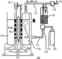
- FIG. 1 is an explanatory diagram of an ammonia electrolyzer (No. 1);
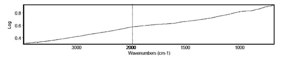
- FIG. FIG. 2 is an explanatory diagram of an ammonia electrolyzer (No. 2); It is explanatory drawing of the electrolytic device (3) of ammonia. It is explanatory drawing of the electrolytic device (4) of ammonia. It is a chart of IR measurement of the sintered body (a1). It is a chart of IR measurement of Ketjenblack EC (EC300J).
- n- is normal, "s-” is secondary, “t-” is tertiary, “o-” is ortho, “m-” is meta, and “p-” is Para and “ t Bu” represent a t-butyl group.
- C a -C b alkyl group is a monovalent alkyl group produced by losing one hydrogen atom from a linear, branched or cyclic aliphatic hydrocarbon having a to b carbon atoms.
- n-octyl group represents a group such as methyl group, ethyl group, n-propyl group, isopropyl group, cyclopropyl group, n-butyl group, isobutyl group, s-butyl group, t-butyl group, cyclobutyl group, n-pentyl group, isopentyl group, neopentyl group, t-pentyl group, 1,1-dimethylpropyl group, cyclopentyl group, n-hexyl group, isohexyl group, 3-methylpentyl group, 2,2-dimethylbutyl group, 2,3-dimethylbutyl group, cyclohexyl group, n-heptyl group, 2-methylhexyl group, 3-ethylpentyl group, n-octyl group, 2,2,4-trimethylpentyl group, 2,5-dimethylhex
- a C a -C b alkoxy group represents a monovalent group in which the above-described alkyl group having a to b carbon atoms is bonded to oxygen, for example, a methoxy group , ethoxy group, n-propoxy group, isopropoxy group, cyclopropoxy group, n-butoxy group, isobutoxy group, s-butoxy group, t-butoxy group, cyclobutoxy group, n-pentoxy group, isopentoxy group, neopentoxy group, t-pentoxy group, 1,1-dimethylpropoxy group, cyclopentoxy group, n-hexythoxy group, isohexyxy group, 3-methylpentoxy group, 2,2-dimethylbutoxy group, 2,3-dimethylbutoxy group, cyclohexy Specific examples include thoxy group, n-heptoxy group, 2-methylhexyoxy group, 3-ethylp
- halogen atoms in the present specification include fluorine atoms, chlorine atoms, bromine atoms, iodine atoms, and the like.
- Ar 6 aryl group in this specification represents a monovalent group formed by losing one hydrogen atom from an aromatic ring of an aromatic hydrocarbon having 6 carbon atoms, such as a phenyl group, from the 2-position
- examples thereof include a phenyl group having a substituent at least one of the 6-positions.
- Substituents on the aromatic ring of Ar 6 aryl include halogen atoms such as fluoro, chloro, bromo and iodo groups, methyl group, trifluoromethyl group, ethyl group, n-propyl group and isopropyl group, Examples include n-butyl group, isobutyl group, s-butyl group and t-butyl group.
- Ar 6 aryl group examples include a phenyl group, o-fluorophenyl group, m-fluorophenyl group, p-fluorophenyl group, o-trifluoromethylphenyl group, m-trifluoromethylphenyl group, p-trifluorophenyl group, fluoromethylphenyl group, o-chlorophenyl group, m-chlorophenyl group, p-chlorophenyl group, o-bromophenyl group, m-bromophenyl group, p-bromophenyl group, o-tolyl group, m-tolyl group, p- tolyl group, o-ethylphenyl group, m-ethylphenyl group, p-ethylphenyl group, o-(t-butyl)phenyl group, m-(t-butyl)phenyl group, m
- the method for producing ammonia according to the present embodiment can be carried out in a production apparatus that performs electrolysis.
- a production apparatus that performs electrolysis is sometimes referred to as an electrolytic apparatus, and is composed of an electrolytic cell, a nitrogen gas supply means, an ammonia recovery means, and an exhaust gas removal means. Details of the electrolytic apparatus will be described later.
- the electrolytic cell is composed of an electrode, an electrolyte bath, a nitrogen gas supply port, and an exhaust gas outlet.
- the anode is the electrode in which the oxidation reaction occurs
- the cathode is the electrode in which the reduction reaction occurs.
- a complex represented by a molybdenum complex and the like in the presence of a complex represented by a molybdenum complex and the like at the cathode and a solid catalyst, electrons from a power source, protons from a proton source arranged in an electrolytic device, and nitrogen gas from a supply means is a method of producing ammonia from nitrogen molecules by donating nitrogen molecules of
- a combination of a complex and a solid catalyst is used at the cathode as a catalyst for producing ammonia.
- a catalyst in the form of a combination of this complex and a solid catalyst may be referred to as a catalyst body in this specification.
- the complex in the method for producing ammonia of the present embodiment includes (A) 2,6-bis(dialkylphosphinomethyl)pyridine as a PNP ligand (wherein the two alkyl groups may be the same or different, and the pyridine ring at least one hydrogen atom of which may be substituted with an alkyl group, an alkoxy group or a halogen atom), (B) N,N-bis(dialkylphosphinomethyl)dihydrobenzimidazo as a PCP ligand molybdenum complex having ridene (wherein the two alkyl groups may be the same or different, and at least one hydrogen atom in the benzene ring may be substituted with an alkyl group, an alkoxy group, or a halogen atom), (C) Molybdenum complexes with bis(dialkylphosphinoethyl)arylphosphines (wherein the two alkyl groups may be the same or different) as PPP ligand
- examples of the alkyl group include C 1 to C 10 alkyl groups, preferably having 1 to 10 carbon atoms, more preferably 3 to 6 carbon atoms, isopropyl groups, t-butyl groups, cyclohexyl groups are even more preferred.
- the alkoxy group includes, for example, a C 1 to C 8 alkoxy group and a benzyloxy group, preferably having 1 to 8 carbon atoms, and when the alkoxy group is a benzyloxy group.
- the benzyloxy group may have at least one hydrogen atom on the benzene ring substituted with a resin.
- Halogen atoms include, for example, fluorine, chlorine, bromine, and iodine atoms.
- R 1 and R 2 are alkyl groups that may be the same or different, X is an iodine atom, a bromine atom or a chlorine atom, and at least one hydrogen atom on the pyridine ring is an alkyl group , optionally substituted with an alkoxy group or a halogen atom).
- alkyl group, the alkoxy group and the halogen atom include those already exemplified.
- R 1 and R 2 are preferably bulky alkyl groups such as t-butyl, isopropyl or cyclohexyl.
- the hydrogen atoms on the pyridine ring are preferably unsubstituted or substituted with a C 1 -C 10 alkyl group, a C 1 -C 8 alkoxy group or a benzyloxy group at the 4-position hydrogen atom.
- More preferred alkoxy groups include benzyloxy groups in which at least one hydrogen atom on the benzene ring is substituted with a resin, and the resins include chloromethyl resins (e.g., polymer-bonded 5-[4-( Chloromethyl)phenyl]pentyl]styrene, polymer-bound 4-(benzyloxy)benzyl chloride, polymer-bound 4-methoxybenzhydryl chloride), (chloromethyl)polystyrene, Merrifield resin, JandaJel-Cl® etc. Of these, (chloromethyl) polystyrene, Merrifield resin and JandaJel-Cl® are preferred.
- chloromethyl resins e.g., polymer-bonded 5-[4-( Chloromethyl)phenyl]pentyl]styrene, polymer-bound 4-(benzyloxy)benzyl chloride, polymer-bound 4-methoxybenzhydryl chloride
- the molybdenum complex (B) has the following formula (B1) or (B2) (wherein R 1 and R 2 are C 1 -C 10 alkyl groups which may be the same or different, X is an iodine atom, a bromine atom or a chlorine atom, and the molybdenum complex of (B1) at least one hydrogen atom on the benzene ring may be substituted with a C 1 -C 10 alkyl group, a C 1 -C 8 alkoxy group or a halogen atom).
- Examples of the C 1 -C 10 alkyl group, the C 1 -C 8 alkoxy group and the halogen atom include those already exemplified.
- R 1 and R 2 are preferably bulky alkyl groups such as t-butyl, isopropyl or cyclohexyl.
- R 3 and R 4 of the molybdenum complex (B2) each independently represent an electron withdrawing group, and R 3 and R 4 may be an electron withdrawing group, and when R 3 is an electron withdrawing group , R 4 may be a hydrogen atom.
- An electron-withdrawing group is also called an electron-withdrawing group or an electron-accepting group. It is a theory that focuses on changes in the electron density and bonding state of a substance and tries to interpret it as unified as possible. By effect, it refers to a substituent that attracts electrons from the bonding electron side compared to a hydrogen atom.
- Examples of the electron-withdrawing group include substituents that have electron-donating mesomeric effect but greatly contribute to electron-withdrawing in inductive effect, and substituents that have electron-withdrawing mesomeric effect and inductive effect.
- substituents that have electron-withdrawing mesomeric effect and inductive effect are electron-donating
- substituents that contribute significantly to the electron-withdrawing properties of the inductive effect include a fluorine atom, a chlorine atom, a bromine atom, an iodine atom, —CH 2 Cl, or —CH ⁇ CHNO 2 .
- substituents having electron-withdrawing mesomeric and inductive effects include quaternary ammonium groups, trifluoromethyl groups, perfluoroalkyl groups, trichloromethyl groups, and cyano groups with anions as counterions.
- examples of the quaternary ammonium group include trialkylammonium groups, such as trimethylammonium group, triethylammonium group, tributyl An ammonium group etc. are mentioned.
- Counter ions for the nitrogen atoms constituting the quaternary ammonium group include hexafluorophosphate ion, hexachloroantimonate ion, trifluoromethanesulfonate ion, tetrafluoroborate ion, phosphate ion, sulfonate ion, chloride, bromide, iodide, hydroxide and the like.
- R 3 and R 4 are preferably a fluorine atom, a chlorine atom, a bromine atom, an iodine atom and a trifluoromethyl group, more preferably a chlorine atom and a trifluoromethyl group.
- the molybdenum complex of (C) for example, the formula (C1) (wherein R 1 and R 2 are C 1 -C 10 alkyl groups which may be the same or different, R 5 is an Ar 6 aryl group, X is an iodine atom, a bromine atom or a chlorine atom and molybdenum complexes represented by Examples of the C 1 -C 10 alkyl group include those already exemplified. Examples of the C 1 -C 10 alkyl group and Ar 6 aryl group include those already exemplified. R 1 and R 2 are preferably bulky alkyl groups such as t-butyl, isopropyl or cyclohexyl. A phenyl group is preferred as R5 .
- the molybdenum complex (D) As the molybdenum complex (D), the formula (D1) or (D2) (wherein R 5 and R 6 are Ar 6 aryl groups which may be the same or different, R 7 is a C 1 -C 10 alkyl group, and n is 2 or 3). and molybdenum complexes.
- the Ar 6 aryl group and the C 1 -C 10 alkyl group are the same as those already exemplified.
- R 5 and R 6 are phenyl groups and R 7 is a C 1 -C 4 alkyl group.
- R 5 and R 6 are phenyl groups and n is 2.
- the solid catalyst in the method for producing ammonia of the present embodiment is a metal catalyst having a single composition or a mixture of a plurality of metal components such as an alloy catalyst, and a metal oxide of a typical element.
- oxide catalysts that are used as transition metal oxides or that have a mixture of a plurality of metal oxides can be mentioned.
- Metal oxides may be utilized as supports for solid catalysts.
- the solid catalyst in the ammonia production method of the present embodiment includes, for example, metal catalysts such as platinum catalysts, gold catalysts, silver catalysts, ruthenium catalysts, iridium catalysts, rhodium catalysts, palladium catalysts, osmium catalysts, tungsten catalysts, lead catalysts, metals such as iron catalysts, chromium catalysts, cobalt catalysts, nickel catalysts, manganese catalysts, vanadium catalysts, molybdenum catalysts, gallium catalysts, aluminum catalysts, and alloys thereof; Titanium, vanadium oxide, chromium oxide, manganese oxide, iron oxide, cobalt oxide, nickel oxide, copper oxide, zinc oxide, niobium pentoxide, molybdenum oxide, cerium oxide, samarium oxide, ruthenium oxide, rhodium oxide, silver oxide, tantalum oxide , tungsten oxide, osmium oxide, iridium oxide, indium oxide, platinum oxide, gold oxide
- the solid catalyst used on the cathode side is defined as a cathode solid catalyst
- preferable cathode solid catalysts are platinum catalyst, gold catalyst, iridium catalyst, palladium catalyst, molybdenum catalyst, zinc oxide, aluminum oxide, molybdenum oxide, and cerium oxide.
- platinum catalyst, gold catalyst, zinc oxide, aluminum oxide, cerium oxide and samarium oxide are platinum catalyst, gold catalyst, zinc oxide, aluminum oxide, cerium oxide and samarium oxide.
- the cathode-side catalyst which is a catalyst obtained by combining a complex and a cathode solid catalyst in the method for producing ammonia of the present embodiment, is defined as a cathode catalyst.
- the cathode catalyst layer 103 for producing ammonia of the present embodiment includes a catalyst carrier, an electron conductor, an electrolyte and a gas diffusion layer in addition to a cathode catalyst body which is a catalyst in which a complex and a cathode solid catalyst are combined. is.
- the cathode catalyst layer 103 comprising a cathode catalyst body, a catalyst carrier, an electron conductor, an electrolyte, and a gas diffusion layer, which is a combination of a complex and a cathode solid catalyst, is replaced by a gas diffusion electrode 133 (Gas Diffusion Electrode, hereinafter referred to as " Also referred to as GDE).
- the reaction field forming material in the method for producing ammonia of the present embodiment means transport of reaction gas, electrons and protons to the complex and/or solid catalyst in the cathode catalyst layer and/or anode catalyst layer. It is a material for forming an accelerating reaction field, and examples thereof include rare earth metal-carbon composites and sintered bodies.
- a rare earth metal-carbon-based bond is a reaction of firing a conventional conductive carbon material and an aromatic compound having a phenolic hydroxyl group to obtain a fired body, and then combining the fired body with a rare earth metal ion. It is a complex of a rare earth metal ion and the fired body, which can be obtained by performing a reaction to obtain a complex with or firing.
- a "fired body” is defined as a fired mixture of an aromatic compound having a phenolic hydroxyl group and a conductive carbon material.
- a complex of the fired body and the rare earth metal ion, in which the rare earth metal ion forms a complex with the substituent or structure of the fired body is defined as a "rare earth metal-carbon-based bond". do.
- aromatic compounds having a phenolic hydroxyl group in the fired body of the present embodiment include monocyclic or condensed polycyclic aromatic compounds having one or more phenolic hydroxyl groups.
- 1 to 6 phenols which are monocyclic aromatic compounds and have 1 to 6 phenolic hydroxyl groups, can be mentioned.
- Phenols which are monocyclic aromatic compounds and have one phenolic hydroxyl group include, for example, phenol, ethylphenol, pt-butylphenol, o-cresol, m-cresol, p-cresol, 2,3 -xylenol, 2,4-xylenol, 2,5-xylenol, 2,6-xylenol, thymol, mesitol, butoidcumenol, 2,6-di-t-butyl-p-cresol, pentamethylphenol, o- Hydroxystyrene, m-hydroxystyrene, p-hydroxystyrene, capicol, o-allylphenol, anol, diethylstilbestrol, p-(methylthio)phenol, o-aminophenol, m-aminophenol, p-aminophenol, o -(methylamino)phenol, m-(methyla
- Phenols that are monocyclic aromatic compounds and have two phenolic hydroxyl groups include, for example, catechol, resorcinol, hydroquinone, 3,4-toluenediol, 2,5-toluenediol, and 3,5-toluenediol. , 2,4-toluenediol, urushiol, p-xylene-2,6-diol, m-xylene-4,6-diol, p-xylene-2,5-diol, 2-isopropyl-5-methylhydroquinone, etc. are mentioned.
- Phenols which are monocyclic aromatic compounds and have three phenolic hydroxyl groups include, for example, pyrogallol, 1,2,4-benzenetriol, phloroglycinol, 2-methylphloroglycinol, m-xylene- 2,4,6-triol, 2,4,6-trimethylphlologlycinol, and the like.
- Phenols which are monocyclic aromatic compounds and have four phenolic hydroxyl groups include, for example, 1,2,3,5-benzenetetraol and 1,2,4,5-benzenetetraol. be done. Examples of phenols that are monocyclic aromatic compounds and have six phenolic hydroxyl groups include hexahydroxybenzene.
- the monocyclic aromatic compound having a phenolic hydroxyl group 3 to 6 phenols having 3 to 6 phenolic hydroxyl groups are more preferable, and the monocyclic aromatic compound has 3 phenolic hydroxyl groups.
- Phenols having the following formula (I) are more preferable, and phloroglucinol represented by the following formula (I) is particularly preferable.
- Condensed polycyclic aromatic compounds include naphthalene, azulene, heptalene, biphenylene, acenaphthylene, fluorene, phenalene, phenanthrene, anthracene, aceanthrylene, triphenylene, pyrene, chrysene, tetracene, perylene, pentacene, picene, coronene, and the like. and naphthalene, anthracene and triphenylene are preferred.
- Condensed polycyclic aromatic compounds having a phenolic hydroxyl group include, for example, 1,2-dihydroxynaphthalene, 1,3-dihydroxynaphthalene, 1,4-dihydroxynaphthalene, 1,5-dihydroxynaphthalene, 1,6- dihydroxynaphthalene, 2,3-dihydroxynaphthalene, 2,4-dihydroxynaphthalene, 2,5-dihydroxynaphthalene, 2,6-dihydroxynaphthalene, 1,3,8-trihydroxynaphthalene, 9,10-anthracene or 2,3 ,6,7,10,11-hexahydroxytriphenylene, preferably 2,6-dihydroxynaphthalene, 1,3,8-trihydroxynaphthalene, 9,10-anthracene and 2,3,6,7 , 10,11-hexahydroxytriphenylene, and more preferably 2,3,6,7,10,11-hexahydroxytriphenylene represented by the following formula (II).
- Aromatic compounds having a phenolic hydroxyl group may be used singly or in combination of two or more.
- Carbon black, carbon nanotubes, and the like are examples of the conductive carbon material (hereinafter also referred to as "carbon material") of the present embodiment.
- Examples of carbon black include ketjen black, ketjen black EC, channel black, oil furnace black, vulcan, furnace black, thermal black, acetylene black, lamp black, graphitized black, oxide black, etc., which have good conductivity. Therefore, acetylene black, Ketjenblack, and Ketjenblack EC are preferred, and Ketjenblack and Ketjenblack EC are more preferred.
- One type of carbon black may be used alone, or two or more types may be used in combination. Carbon black may be surface-treated.
- carbon nanotubes for example, vapor growth, catalytic vapor growth, catalytic chemical vapor deposition, chemical vapor deposition, super multiplication, catalytic carbon deposition, arc discharge, laser evaporation, etc.
- the resulting single-walled nanotubes and multi-walled carbon nanotubes can be exemplified, and these can take any form such as a needle-like, coil-like, or tube-like form.
- the carbon nanotube tube it has a cylindrical shape by winding one sheet of graphite with a carbon hexagonal network surface, and it is a multi-wall carbon nanotube wound in three or more layers (multi-wall carbon nanotube), one of graphite.
- Single-walled carbon nanotube (single-walled carbon nanotube: SWNT), double-walled carbon nanotube (double-walled carbon nanotube: DWNT), vapor-grown carbon fiber (VGCF, Showa Denkosha) (registered trademark) of the company).
- TC series such as TC-2010, TC-2020, TC-3210L, TC-1210LN (manufactured by Toda Kogyo Co., Ltd.), spur growth method CNT (National Research and Development Agency New Energy and Industrial Technology Development Organization ), eDIPS-CNT (manufactured by the New Energy and Industrial Technology Development Organization), SWNT series (manufactured by Meijo Nano Carbon Co., Ltd.: product name), VGCF such as VGCF, VGCF-H, and VGCF-X ( Registered trademark) series (manufactured by Showa Denko Co., Ltd.: registered trademark), FloTube series (manufactured by CNano Technology: trade name), AMC (manufactured by Ube Industries, Ltd.: trade name), NANOCYL NC7000 series (manufactured by Nanocyl S.A.: Baytubes (manufactured by Bayer: trade name), GRAPHISTRENGTH (manufactured
- Carbon nanotubes may be used singly or in combination of two or more. Carbon nanotubes may be surface-treated. Furthermore, carbon black and carbon nanotubes may be used in combination.
- the conductive carbon material is preferably at least one selected from the group consisting of Ketjenblack, Ketjenblack EC, and carbon nanotubes.
- the carbon material having conductivity is selected from the group consisting of hydroxyl group, carboxyl group, carbonyl group, formyl group, sulfonic acid group, oxysulfonic acid group, carboxylic acid anhydride structure, chromene structure, lactone structure, ester structure and ether structure. It is preferable to have at least one substituent selected from the group consisting of a hydroxyl group, a carboxyl group, a formyl group, a carboxylic anhydride structure, a lactone structure, an ester structure and an ether structure. More preferably, it has at least one substituent selected from the group consisting of a hydroxyl group, a lactone structure and an ester structure.
- a method for manufacturing the sintered body of this embodiment will be described. It is obtained by firing a mixture of an aromatic compound having a phenolic hydroxyl group and a conductive carbon material.
- the firing temperature may be any temperature at which the aromatic compound having a phenolic hydroxyl group can be carbonized, preferably 150 to 1000°C, more preferably 200 to 600°C, even more preferably 250 to 450°C. Firing is carried out at a firing temperature, preferably for 1 to 10 hours, more preferably for 1 to 5 hours. Firing is preferably carried out in air or an inert gas. Nitrogen, argon, etc. are mentioned as an inert gas.
- the metal species of the rare earth metal ion in the rare earth metal-carbon-based bond which is the reaction field forming material of the present embodiment, includes scandium, yttrium, lanthanum, cerium, praseodymium, neodymium, promethium, samarium, europium, gadolinium, terbium, and dysprosium.
- holmium, erbium, thulium, ytterbium or lutetium preferably scandium, yttrium, lanthanum, cerium, praseodymium, neodymium, samarium, europium, gadolinium and ytterbium, scandium, yttrium, lanthanum, cerium, samarium, Europium and ytterbium are more preferred.
- a complex is formed between the substituent of the fired body and the rare earth metal ion.
- the complex structure between the substituent of the fired body and the rare earth metal ion the complex structure of the substituent derived from the surface of the carbon material and the carbon deficiency part and the rare earth metal ion and the hydroxyl group derived from the aromatic compound having a phenolic hydroxyl group. and a complex structure with a rare earth metal ion. These may be either one of the complex structures or both complex structures.
- a hydroxyl group derived from the carbon material As the complex structure between the substituent derived from the surface of the carbon material and the carbon deficiency portion and the rare earth metal ion, a hydroxyl group derived from the carbon material, a carboxyl group, a carbonyl group, a formyl group, a sulfonic acid group, an oxysulfonic acid group, a carboxylic acid
- At least one substituent selected from the group consisting of an anhydride structure, a chromene structure, a lactone structure, an ester structure and an ether structure includes a bond between a formally deprotonated monovalent anion and a rare earth metal ion.
- the rare earth metal ion forms a complex structure via —O— with the surface of the carbon material and the substituents on the carbon-deficient portion. More preferably, the rare earth metal ion forms one or more cyclic structures, ie, a chelate ring, with the surface of the carbon material via —O— for the reason of increasing its stability. mentioned.
- a partial structure represented by the following formula (a) formed by firing an aromatic compound having a phenolic hydroxyl group and a rare earth metal As a complex structure between a hydroxyl group derived from an aromatic compound having a phenolic hydroxyl group and a rare earth metal ion, a partial structure represented by the following formula (a) formed by firing an aromatic compound having a phenolic hydroxyl group and a rare earth metal
- a complex structure with an ion for example, a partial structure represented by formula (b) can be mentioned.
- a rare earth metal-carbon-based bond in which the rare earth metal ion forms a complex structure with the substituents of the sintered body can be produced by step 1A. From the viewpoint of durability, it is preferable to perform step 2A after step 1A.
- step 1A the fired body of the present invention and a rare earth metal compound are reacted to form a complex between the rare earth metal ion and the substituent of the fired body of the present invention, and the complex of the fired body and the rare earth metal ion is a rare earth.
- a metal-carbon composite is obtained.
- the reaction between the fired body and the rare earth metal compound is performed by reacting the fired body and the rare earth metal compound in a solvent.
- Substituents of the fired product used in the reaction of step 1A include hydroxyl group, carboxyl group, carbonyl group, formyl group, sulfonic acid group, oxysulfonic acid group, carboxylic acid anhydride structure, chromene structure, lactone structure, ester structure and ether It is preferably at least one selected from the group consisting of structures, and at least one selected from the group consisting of a hydroxyl group, a carboxyl group, a formyl group, a carboxylic anhydride structure, a lactone structure, an ester structure and an ether structure. It more preferably has a substituent, and more preferably at least one selected from the group consisting of a hydroxyl group, a lactone structure, an ester structure and an ether structure.
- rare earth metal alkoxide compounds include rare earth metal triisopropoxide.
- rare earth metal triisopropoxides include scandium triisopropoxide, yttrium triisopropoxide, lanthanum triisopropoxide, cerium triisopropoxide, praseodymium triisopropoxide, neodymium triisopropoxide, and promethium triisopropoxide.
- rare earth metal acetylacetonato compounds include tris(acetylacetonato)scandium(III), tris(acetylacetonato)yttrium(III), tris(acetylacetonato)lanthanum(III), tris(acetylacetonato) ) Cerium(III), Tris(acetylacetonato)neodymium(III), Tris(acetylacetonato)promethium(III), Tris(acetylacetonato)samarium(III), Tris(acetylacetonato)eurobium(III), Tris(acetylacetonato)gadolinium (III), Tris(acetylacetonato)terbium(III), Tris(acetylacetonato)dysprosium(III), Tris(acetylacetonato)holmium(III), Tris(acetylacetonato)
- Step 1 is, for example, sodium hydride, lithium hydride, sodium hydroxide, 1,8-diazabicyclo-5,4,0-undec-7-ene (DBU), trimethylamine, triethylamine, tripropylamine, N-ethyl It can also be carried out in the presence of methylbutylamine, tributylamine, N,N-dimethylbenzylamine, N,N-diethylbenzylamine, tribenzylamine and the like. Among these, sodium hydride and lithium hydride are preferred.
- the solvent used in step 1A may be any non-aqueous solvent capable of dispersing the fired body and dissolving or dispersing the rare earth metal compound.
- 1,3-Propanesultone which is the target of the reaction, can also serve as a solvent.
- Toluene, tetrahydrofuran, dimethylsulfoxide, N,N-dimethylformamide and 1,3-propanesultone are preferred, and tetrahydrofuran is more preferred.
- the reaction temperature in step 1A is preferably -10 to 200°C, more preferably 10 to 160°C, still more preferably 15 to 140°C.
- the reaction time of step 1A is preferably 1 to 500 hours, more preferably 2 to 300 hours, even more preferably 5 to 150 hours.
- step 2A the rare earth metal-carbon composite, which is a complex of the sintered body obtained in step 1A and the rare earth metal, is washed with acid and water. Before being used in a fuel cell device, the complex that has undergone step 2A is washed to eliminate reacting substituents and impurities. Excellent.
- the acid used in step 2A include inorganic acids such as sulfuric acid, hydrochloric acid, nitric acid, sulfurous acid, nitrous acid, and phosphoric acid, and organic acids such as acetic acid, lactic acid, oxalic acid, citric acid, and formic acid. Sulfuric acid is preferable because it can be used for fuel cell devices and impurities are less likely to remain.
- ⁇ Rare earth metal-carbon-based composite manufacturing method B> A rare earth metal-carbon-based bond in which rare earth metal ions form a complex structure with the substituents of the fired body can be produced by step 1B, and step 2B may be performed after step 1B, if necessary. .
- step 1B a mixture of the fired body of the present invention and a rare earth metal compound is fired to obtain a complex of the fired body and the rare earth metal ion in which a complex structure of the rare earth metal ion and the substituent of the fired body is formed.
- Substituents of the fired body used in the reaction of step 1B include hydroxyl group, carboxyl group, carbonyl group, formyl group, sulfonic acid group, oxysulfonic acid group, carboxylic acid anhydride structure, chromene structure, lactone structure, ester structure and ether It is preferably at least one selected from the group consisting of structures, and at least one substituent selected from the group consisting of a hydroxyl group, a carboxyl group, a formyl group, a carboxylic anhydride structure, a lactone structure and an ester structure. More preferably, it has at least one selected from the group consisting of a hydroxyl group, a lactone structure, an ester structure and an ether structure.
- the rare earth metal compound used in step 1B includes the same compound as the compound described in step 1A.
- the firing temperature in step 1B is preferably 100-1000°C, more preferably 150-600°C, and even more preferably 200-500°C.
- the firing time in step 1B is preferably 1 to 500 hours, more preferably 2 to 300 hours, and even more preferably 5 to 150 hours.
- the atmosphere for firing in step 1B can be performed under the atmosphere or under an inert gas.
- the atmosphere include air, and examples of the inert gas include nitrogen and argon.
- the firing atmosphere is preferably under an inert gas, and the inert gas is preferably nitrogen.
- the catalyst carrier in the cathode catalyst layer 103 of the present embodiment may conduct electrons, and is not particularly limited as long as it supports the catalyst of the present embodiment.
- catalyst carriers include carbon black, carbon materials, metal meshes, metal foams, metal oxides, composite oxides, polymer electrolytes, and ionic liquids. Further, when the catalyst carrier is used in the electrode, it not only plays the role of supporting the catalyst, but also participates as a catalyst or co-catalyst in the reaction occurring at the electrode.
- Examples of carbon black include channel black, furnace black, thermal black, acetylene black, ketjen black, ketjen black EC, and the like.
- Examples of carbon materials include carbonizing and activating materials containing various carbon atoms. Treated activated carbon, coke, natural graphite, artificial graphite, graphitized carbon, and the like can be mentioned.
- Metal meshes include metal meshes such as nickel or titanium.
- Metal foams include, for example, aluminum, magnesium, titanium, Metal foams such as zinc, iron, tin, lead, or alloys containing these metal oxides include, for example, aluminum oxide, zirconium oxide, titanium oxide, vanadium oxide, chromium oxide, manganese oxide, iron oxide, Cobalt oxide, nickel oxide, copper oxide, zinc oxide, niobium pentoxide, molybdenum oxide, ruthenium oxide, rhodium oxide, silver oxide, tantalum oxide, tungsten oxide, osmium oxide, iridium oxide, indium oxide, platinum oxide, gold oxide, oxide Magnesium, silica and the like can be mentioned, and examples of composite oxides include silica-alumina, silica-magnesia and the like.
- polymer electrolytes examples include fluorine-based polymer electrolytes and hydrocarbon-based polymer electrolytes.
- fluorine-based polymer electrolytes examples include Nafion (registered trademark) from DuPont, Aquivion (registered trademark) from Solvay, Flemion (registered trademark) from AGC, and Aciplex (registered trademark) from Asahi Kasei.
- examples include sulfonic acid polymers, hydrocarbon sulfonic acid polymers, and partially fluorine-introduced hydrocarbon sulfonic acid polymers.
- Hydrocarbon polymer electrolytes include, for example, sulfonated polyetherketone, sulfonated polyethersulfone, sulfonated polyetherethersulfone, sulfonated polysulfide, and sulfonated polyphenylene.
- ionic liquids include imidazolium salts, pyridinium salts, ammonium salts, phosphonium salts, pyrrolidinium salts, piperidinium salts, and sulfonium salts.
- the ionic liquid of this embodiment will be described below.
- imidazolium salts include formula (1): Those represented by are mentioned.
- R 1a to R 5a may be the same or different, and may each be a hydrogen atom, a C 1 to C 10 alkyl group, an allyl group, or a vinyl group.
- X - in formula (1) includes, for example, chloride ion, bromide ion, iodine ion, tetrafluoroborate, trifluoro(trifluoromethyl)borate, dimethyl phosphate ion, diethyl phosphate ion, hexafluorophosphate ion, fart, tris(pentafluoroethyl)trifluorophosphate, trifluoroacetate, methylsulfate, trifluoromethanesulfonate, bis(trifluoromethanesulfonyl)imide and the like.
- formula (1) include, for example, 1-allyl-3-methylimidazolium ion, 3-ethyl-1-vinylimidazolium ion, 1-methylimidazolium ion, 1-ethylimidazolium ion, 1- n-propylimidazolium ion, 1,3-dimethylimidazolium ion, 1,2,3-trimethylimidazolium ion, 1-ethyl-3-methylimidazolium ion, 1-ethyl-2,3-dimethylimidazolium ion , 1,2,3,4-tetramethylimidazolium ion, 1,3-diethylimidazolium ion, 1-methyl-3-n-propylimidazolium ion, 1-ethyl-3-methylimidazolium ion, 2- ethyl-1,3-dimethylimidazolium ion, 1-ethyl-2,3-dda
- pyridinium salts include formula (2): Those represented by are mentioned.
- R 1b to R 6b may be the same or different, and each includes a hydrogen atom, a hydroxymethyl group, or a C 1 to C 6 alkyl group.
- X 1 - in formula (2) includes the same ones as in formula (1).
- formula (2) include, for example, 1-butyl-3-methylpyridinium ion, 1-butyl-4-methylpyridinium ion, 1-butyl-pyridinium ion, 1-ethyl-3-methylpyridinium ion, 1 -ethylpyridinium ion, 1-ethyl-3-(hydroxymethyl)pyridinium ion and other pyridinium ions, and salts of X 1 - in the formula (1).
- ammonium salts include formula (3): Those represented by are mentioned.
- R 1c to R 4c may be the same or different, and are each a hydrogen atom, a methoxyethyl group, a phenylethyl group, a methoxypropyl group, a cyclohexyl group, or a C 1 to C 8 alkyl group. groups.
- X 1 - in formula (3) includes the same ones as in formula (1).
- formula (3) examples include triethylpentylammonium ion, diethyl(methyl)propylammonium ion, methyltri-n-octylammonium ion, trimethylpropylammonium ion, cyclohexyltrimethylammonium ion, diethyl(2-methoxyethyl) -methylammonium ion, ethyl(2-methoxyethyl)-dimethylammonium ion, ethyl(3-methoxypropyl)dimethyl-ammonium ion, ethyl(dimethyl)(2-phenylethyl)-ammonium ion, etc. and the above formula ( Examples thereof include salts with X 1 - in 1).
- phosphonium salts include formula (4): Those represented by are mentioned.
- R 1d to R 4d may be the same or different, and each includes a hydrogen atom, a methoxyethyl group, or a C 1 to C 10 alkyl group.
- X 1 - in formula (3) includes the same ones as in formula (1).
- formula (4) include phosphonium ions such as tributylmethylphosphonium ion, tetrabutylphosphonium ion, trihexyl(tetradecyl)phosphonium ion, trihexyl(ethyl)phosphonium ion, and tributyl(2-methoxyethyl)-phosphonium ion. and salts of X 1 — in formula (1) above.
- pyrrolidinium salts include formula (5): Those represented by are mentioned.
- R 1e to R 2e may be the same or different, and each includes a hydrogen atom, an allyl group, a methoxyethyl group, or a C 1 to C 8 alkyl group.
- X 1 - in formula (5) includes the same ones as in formula (1).
- formula (5) include, for example, 1-allyl-1-methylpyrrolidinium ion, 1-(2-methoxyethyl)-1-methylpyrrolidinium ion, 1-butyl-1-methylpyrrolidinium ion, A salt of a pyrrolidinium ion such as 1-methyl-1-propylpyrrolidinium ion, 1-octyl-1-methylpyrrolidinium ion, 1-hexyl-1 - methylpyrrolidinium ion and X- in the formula (1) mentioned.
- piperidinium salts include formula (6): Those represented by are mentioned.
- R 1f to R 2f may be the same or different, and each includes a hydrogen atom or a C 1 to C 6 alkyl group.
- X 1 - in formula (6) includes the same ones as in formula (1).
- formula (6) include, for example, salts of piperidinium ions such as 1-butyl-1-methylpiperidinium ion and 1-methyl-1-propylpiperidinium ion and X - in formula (1) above. are mentioned.
- sulfonium salts include formula (7): Those represented by are mentioned.
- R 1g to R 3g may be the same or different, and each includes a hydrogen atom or a C 1 to C 4 alkyl group.
- X 1 - in formula (3) includes the same ones as in formula (1).
- formula (7) include salts of sulfonium ions such as triethylsulfonium ion and trisulfonium ion and X 1 ⁇ in formula (1).
- ionic liquid 1-allyl-3-methylimidazolium chloride, 1-butyl-3-methylimidazolium bromide, 1-butyl-3-methylimidazolium tetrafluoroborate, 1-butyl-3- Methylimidazolium hexafluorophosphate, 1-butyl-3-methylimidazolium trifluoromethanesulfonate, 1-butyl-3-methylimidazolium bis(trifluoromethanesulfonyl)imide, 1-butyl-3-methylimidazolium iodide , 1-butyl-3-methylimidazolium tris(pentafluoroethyl)trifluorotrifluorophosphate, 1-butyl-3-methylimidazolium trifluoro(trifluoromethyl)borate, 1-butyl-2,3-dimethylimidazolium lithium trifluoromethanesulfonate, 1-butyl-3-methylimid
- the catalyst carrier of the present embodiment carbon black, Ketjenblack, Ketjenblack EC, Nafion (registered trademark), 1-butyl-3-methylimidazolium bis(trifluoromethanesulfonyl)imide, 1-butyl -1-methylpyrrolidinium bis(fluorosulfonyl)imide, 1-butyl-3-methylimidazolium tris(pentafluoroethyl)trifluorotrifluorophosphate are preferred.
- These catalyst carriers may be used singly or in combination of two or more. Carbon black and zinc oxide in combination, Ketjenblack EC and zinc oxide in combination, carbon black and molybdenum oxide. and a combination of Ketjenblack EC and molybdenum oxide are preferred.
- the electron conductor in the cathode catalyst layer 103 of the present embodiment is not particularly limited as long as it conducts electrons.
- carbon black such as channel black, furnace black, thermal black, acetylene black, ketjen black, ketjen black EC, activated carbon obtained by carbonizing and activating materials containing various carbon atoms, coke, natural graphite, artificial graphite, Examples thereof include carbon materials such as graphitized carbon, metal mesh such as nickel or titanium, and metal foam.
- carbon black, Ketjenblack, Ketjenblack EC, nickel metal mesh, titanium metal mesh and metal foam are used because of their high specific surface area and excellent electronic conductivity. is preferable, and titanium metal mesh and metal foam are more preferable because of their excellent durability.
- the electrolyte in the cathode catalyst layer 103 of this embodiment is not particularly limited as long as it is responsible for ion conduction.
- Fluorine-based polymer electrolytes and hydrocarbon-based polymer electrolytes are included.
- fluorine-based polymer electrolytes include Nafion (registered trademark) from DuPont, Aquivion (registered trademark) from Solvay, Flemion (registered trademark) from AGC, and Aciplex (registered trademark) from Asahi Kasei.
- fluorine-based polymer electrolytes include Nafion (registered trademark) from DuPont, Aquivion (registered trademark) from Solvay, Flemion (registered trademark) from AGC, and Aciplex (registered trademark) from Asahi Kasei.
- examples include sulfonic acid polymers, hydrocarbon sulfonic acid polymers, and partially fluorine-introduced hydrocarbon sulf
- Hydrocarbon polymer electrolytes include, for example, sulfonated polyetherketone, sulfonated polyethersulfone, sulfonated polyetherethersulfone, sulfonated polysulfide, and sulfonated polyphenylene.
- the electrolyte in the cathode catalyst layer 103 of the present embodiment those responsible for proton conduction are preferable, and Nafion, Aquivion, Flemion, and Aciplex are preferable.
- the electrolyte may be mixed and used, and preferably contains a perfluoroacid polymer such as Nafion.
- the gas diffusion layer in the cathode catalyst layer 103 of this embodiment is not particularly limited as long as it is responsible for electron conduction, gas diffusion, and electrolyte diffusion. Examples thereof include carbon paper, carbon felt, carbon cloth, and the like.
- the cathode catalyst layer 103 including a complex, a cathode solid catalyst, or a catalyst body that is a complex and a cathode solid catalyst, and including a gas diffusion layer may be referred to as a gas diffusion electrode 133 .
- Examples of carbon paper include Toray's TGP-H-060, TGP-H-090, TGP-H-120, TGP-H-060H, TGP-H-090H, TGP-H-120H, Electrochem's EC-TP1-030T, EC-TP1-060T, EC-TP1-090T, EC-TP1-120T, SIGRACET 22BB, 28BC, 36BB, 39BB and the like.
- Examples of the carbon cloth include EC-CC1-060, EC-CC1-060T, and EC-CCC-060 manufactured by Electrochem Corporation, Torayca (registered trademark) cloth manufactured by Toray Industries, Inc., and CO6142, CO6151B, CO6343, CO6343B, and CO6347B. , CO6644B, CO1302, CO1303, CO5642, CO7354, CO7359B, CK6244C, CK6273C, CK6261C and the like.
- Examples of carbon felt include H1410 and H2415 manufactured by Freudenberg.
- TGP-H-060, TGP-H-090, TGP-H-060H, TGP-H-090H, and EC-TP1-060T are preferable for the gas diffusion layer in the cathode catalyst layer 103 of this embodiment.
- the proton source arranged in the electrolytic device includes, for example, the electrolyte membrane 102 arranged beside the cathode catalyst layer 103, the electrolytic solution derived from the electrolyte membrane, and the The electrolyte is not particularly limited as long as it is a solution containing an electrolyte and is responsible for proton conduction. These proton sources may be used singly or in combination of two or more.
- solutions in the electrolytic solution in the method for producing ammonia of the present embodiment include water, ionic liquids, methanol, isopropyl alcohol, N,N-dimethylformamide, N,N-dimethylacetamide, dimethylsulfoxide, N-methylpyrrolidone, Diethylamine, hexamethylphosphonic acid triamide, acetic acid, acetonitrile, methylene chloride, trifluoroethanol, nitromethane, sulfolane, pyridine, tetrahydrofuran, dimethoxyethane, propylene carbonate, etc., water and ionic liquids are preferred.
- ionic liquids include those described above, such as imidazolium salts, pyridinium salts, ammonium salts, phosphonium salts, pyrrolidinium salts, piperidinium salts, or sulfonium salts.
- Acids such as sulfuric acid and trifluoromethanesulfonic acid can be added to the ionic liquid and used, and 1-butyl-3-methylimidazolium bis(trifluoromethanesulfonyl) is preferable as the ionic liquid to which the acid is added.
- Examples of the electrolyte contained in the electrolytic solution in the method for producing ammonia of the present embodiment include protons, lithium ions, sodium ions, potassium ions, imidazolium ions, pyridinium ions, quaternary ammonium ions, phosphonium ions, and pyrrolidinium ions. , phosphonium ions, etc.
- Examples include anions singly or in combination.
- One of the electrolytes may be used alone, or two or more of them may be used in combination.
- Examples of quaternary ammonium ions in the electrolyte include triethylpentylammonium ion, diethyl(methyl)propylammonium ion, methyltri-n-octylammonium ion, trimethylpropylammonium ion, cyclohexyltrimethylammonium ion, diethyl(2-methoxyethyl)-methyl ammonium ion, ethyl(2-methoxyethyl)-dimethylammonium ion, ethyl(3-methoxypropyl)dimethyl-ammonium ion, ethyl(dimethyl)(2-phenylethyl)-ammonium ion, tetramethylammonium ion, tetraethylammonium ion, Triethylpentylammonium ion, tetra-n-butylammoni
- imidazolium ions, pyridinium ions, phosphonium ions, pyrrolidinium ions, and phosphonium ions in the electrolyte include those described above.
- the cations that are electrolytes contained in the electrolytic solution of the present embodiment are preferably protons, imidazolium ions, and pyrrolidinium ions, and the anions that are the electrolytes are preferably perchlorate ions and sulfate ions.
- Preferred examples of the catholyte 106 used in the catholyte electrolyte bath 105 of the present embodiment are water, an aqueous sulfuric acid solution, and 1-butyl-3-methylimidazolium bis(trifluoromethanesulfonyl)imide.
- species may be used individually and may use 2 or more types together.
- water and an aqueous sulfuric acid solution are preferable for the anode electrolyte 116 used in the anode electrolyte tank 115 of the present embodiment.
- the electrolyte membrane 102 may be a polymer electrolyte membrane.
- polymer electrolyte membranes include Neocepta (registered trademark) manufactured by ASTOM Corporation and Selemion (registered trademark) manufactured by AGC Corporation. ), Asahi Kasei's Aciplex (registered trademark), Fumatech's Fumasep (registered trademark), Fumatech's fumapem (registered trademark), DuPont's Nafion (registered trademark), Solvay's Aquivion (registered trademark), AGC. and Gore Select (registered trademark) of Gore Japan LLC.
- As the electrolyte membrane 102 Aciplex (registered trademark) manufactured by Asahi Kasei Corporation, Nafion (registered trademark) manufactured by DuPont, Aquivion (registered trademark) manufactured by Solvay, and Flemion (registered trademark) manufactured by AGC are preferable.
- the reaction temperature is preferably -40°C to 120°C, more preferably 0°C to 50°C, which is normal temperature.
- the reaction atmosphere may be a pressurized atmosphere, or usually a normal pressure atmosphere.
- the reaction time is not particularly limited, it can usually be set in the range of several tens of minutes to several tens of hours. For example, after reacting for several hours, it is also possible to once stop the reaction and then react again.
- FIG. 1 shows an ammonia electrolyzer (Part 1) 100 of Example 1 for producing ammonia
- FIG. 2 shows an ammonia electrolyzer (Part 2) 200 of Example 2 for producing ammonia
- An ammonia electrolysis apparatus (part 3) 300 of Example 3 for producing ammonia and an ammonia electrolysis apparatus (part 4) 400 of Example 4 for producing ammonia are shown in FIG. 4, respectively.
- An ammonia electrolysis apparatus (part 1) 100 of the present embodiment includes a cathode 108 and an anode 118, and a membrane electrode assembly 131 in which a cathode catalyst layer 103 and an anode catalyst layer 113 are integrated via an electrolyte membrane 102.
- Ammonia production equipment A cathode catalyst layer 103 is bonded to one side of the electrolyte membrane 102, and a cathode current collector 104 is arranged on the outside thereof, and an anode catalyst layer 113 is bonded to the other side of the electrolyte membrane 102, and the outside thereof.
- the anode current collector 114 is arranged in the .
- the cathode catalyst layer 103 comprises a complex and a cathode solid catalyst
- the anode catalyst layer 113 comprises an anode solid catalyst.
- the manufacturing apparatus includes a cathode electrolyte bath 105 for a catholyte electrolyte 106 in liquid contact with a cathode 108 of a membrane electrode assembly 131, and an anode electrolyte for an anode electrolyte 116 in liquid contact with an anode 118 of a membrane electrode assembly 131.
- a power source for supplying electrons to the cathode 108
- a proton source for supplying protons to the cathode 108
- the proton source is electrolyte membrane 102 , catholyte 106 , anolyte 116 , both electrolyte membrane 102 and catholyte 106 , or both electrolyte membrane 102 and anolyte 116 .
- it is an ammonia production apparatus for producing ammonia from nitrogen molecules by electrolysis.
- the means for supplying nitrogen gas is means for supplying nitrogen gas from a nitrogen cylinder 122 through a pipe 121 via a nitrogen cylinder regulator 123 and a nitrogen gas mass flow controller 124 .
- Ammonia generated at the cathode 108 can be collected in the cathode electrolyte bath 105 of the cathode electrolyte 106 and the diluted sulfuric acid aqueous solution bath 125 for collecting ammonia.
- the by-produced hydrogen and unreacted nitrogen pass through a pipe 121, a diluted sulfuric acid aqueous solution tank 125 for collecting ammonia, and are discharged to the outside through a draft device 126.
- the ammonia electrolyzer (part 2) 200 of the present embodiment is an ammonia production apparatus that includes a cathode 108 composed of a cathode catalyst layer 103 and a cathode current collector 104 and a metal plate electrode 117 as an anode.
- the cathode catalyst layer 103 comprises a complex and a cathode solid catalyst and is the gas diffusion electrode 133 .
- the manufacturing apparatus includes an anode electrolyte bath 115 for an anode electrolyte 116 in liquid contact with the cathode catalyst layer 103, a power supply (power supply device 101) that supplies electrons to the cathode 108, and a proton source that supplies protons to the cathode 108.
- the gas diffusion layer of the cathode catalyst layer 103 is preferably carbon paper made of polytetrafluoroethylene (hereinafter also referred to as "PTFE") and treated with a fluorocarbon resin for water repellency.
- PTFE polytetrafluoroethylene
- TGP-H-060H, TGP-H-090H, TGP-H-120H, EC-TP1-030T, EC-TP1-060T, EC-TP1-090T or EC-TP1-120T are preferred.
- the source of protons is the anolyte 116 . Furthermore, it is an ammonia production apparatus for producing ammonia from nitrogen molecules by electrolysis.
- the means for supplying nitrogen gas is means for supplying nitrogen gas from a nitrogen cylinder 122 through a pipe 121 via a nitrogen cylinder regulator 123 and a nitrogen gas mass flow controller 124 .
- Ammonia produced at the cathode 108 can be collected in the anode electrolyte tank 115 of the anode electrolyte 116 and the diluted sulfuric acid aqueous solution tank 125 for collecting ammonia.
- the by-produced hydrogen and unreacted nitrogen pass through a pipe 121, a diluted sulfuric acid aqueous solution tank 125 for collecting ammonia, and are discharged to the outside through a draft device 126.
- the ammonia electrolysis apparatus (3) 300 of the present embodiment includes a cathode 108 and an anode 118, and a membrane electrode assembly 131 in which the cathode catalyst layer 103 and the anode catalyst layer 113 are integrated via the electrolyte membrane 102.
- Ammonia production equipment A cathode catalyst layer 103 is bonded to one side of the electrolyte membrane 102, and a cathode current collector 104 is arranged on the outside thereof, and an anode catalyst layer 113 is bonded to the other side of the electrolyte membrane 102, and the outside thereof.
- the anode current collector 114 is arranged in the .
- the cathode catalyst layer 103 comprises a complex and a cathode solid catalyst
- the anode catalyst layer 113 comprises an anode solid catalyst.
- the manufacturing apparatus includes an anode electrolyte tank 115 of an anode electrolyte 116 in liquid contact with an anode 118 of a membrane electrode assembly 131, a power supply (power supply device 101) for supplying electrons to the cathode 108, and protons for supplying protons to the cathode 108.
- a proton source for supplying and means for supplying nitrogen gas to the catholyte 106 and the cathode 108 are provided.
- the proton source is the electrolyte membrane 102 , the anolyte 116 , or both the electrolyte membrane 102 and the anolyte 116 . Furthermore, it is an ammonia production apparatus for producing ammonia from nitrogen molecules by electrolysis.
- the means for supplying nitrogen gas is means for supplying nitrogen gas from a nitrogen cylinder 122 through a pipe 121 via a nitrogen cylinder regulator 123 and a nitrogen gas mass flow controller 124 .
- Ammonia generated at the cathode 108 can be collected in a dilute sulfuric acid aqueous solution tank 125 for collecting ammonia.
- By-produced hydrogen and unreacted nitrogen pass through a pipe 121 , a dilute sulfuric acid aqueous solution tank 125 for collecting ammonia, and are discharged to the outside through a draft device 126 .
- the ammonia electrolysis apparatus (part 4) 400 of the present embodiment includes a cathode 108 comprising a cathode membrane electrode assembly 132 in which a cathode catalyst layer 103 is joined to one side of an electrolyte membrane 102, and a cathode current collector 104, and This is an ammonia production apparatus having a metal plate electrode 117 as an anode.
- Cathode catalyst layer 103 comprises a complex and a cathode solid catalyst.
- the manufacturing apparatus includes an anode electrolyte tank 115 of an anode electrolyte 116 in liquid contact with the electrolyte membrane 102 of the cathode membrane electrode assembly 132, a power supply (power supply device 101) for supplying electrons to the cathode 108, and A proton source for supplying protons and means for supplying nitrogen gas to the cathode 108 are provided.
- the proton source is the electrolyte membrane 102 , the anolyte 116 , or both the electrolyte membrane 102 and the anolyte 116 .
- it is an ammonia production apparatus for producing ammonia from nitrogen molecules by electrolysis.
- the means for supplying nitrogen gas is means for supplying nitrogen gas from a nitrogen cylinder 122 through a pipe 121 via a nitrogen cylinder regulator 123 and a nitrogen gas mass flow controller 124 .
- Ammonia generated at the cathode 108 can be collected in a dilute sulfuric acid aqueous solution tank 125 for collecting ammonia.
- By-produced hydrogen and unreacted nitrogen pass through a pipe 121 , a dilute sulfuric acid aqueous solution tank 125 for collecting ammonia, and are discharged to the outside through a draft device 126 .
- the cathode current collector 104 and the anode current collector 114 in the electrolytic device of the present embodiment are, for example, carbon, metal, oxide, an alloy containing two or more kinds of metals, an oxide containing two or more kinds of metals, Examples include stainless steel, indium tin oxide, and indium zinc oxide.
- metals include titanium, vanadium, chromium, manganese, iron, cobalt, nickel, copper, zinc, niobium, molybdenum, ruthenium, rhodium, silver, tantalum, tungsten, osmium, iridium, indium, platinum, and gold.
- oxides include titanium oxide, vanadium oxide, chromium oxide, manganese oxide, iron oxide, cobalt oxide, nickel oxide, copper oxide, zinc oxide, niobium pentoxide, molybdenum oxide, ruthenium oxide, rhodium oxide, and silver oxide. , tantalum oxide, tungsten oxide, osmium oxide, iridium oxide, indium oxide, platinum oxide, and gold oxide.
- the shape of the current collector is not particularly limited as long as it is a shape through which gas or electrolytic solution can pass. bodies, foams, and the like. In order to prevent corrosion during manufacturing by electrolysis, it is possible to use a current collector plated with gold or the like.
- Nitrogen gas can be supplied from the nitrogen cylinder 122 by controlling the flow rate using the nitrogen cylinder regulator 123 and the nitrogen gas mass flow controller 124 .
- a method of bubbling nitrogen gas into the electrolyte in the cathode electrolyte bath 105 in FIG. 1 and the electrolyte in the anode electrolyte bath 115 in FIG. 2 is also possible. It is also possible to supply nitrogen gas directly to the cathode catalyst layer 103 through the holes in the conductor 104 .
- the electrolytic reaction for producing ammonia in the cathode catalyst layer 103 in the electrolytic device of this embodiment will be described.
- the catalyst body which is a combination of the complex and the solid catalyst of the present embodiment, provides nitrogen gas supplied to the cathode 108, protons supplied to the cathode 108, and electrons supplied from the power supply device 101. , a reaction that produces ammonia occurs, and the reaction formula can be described as "N 2 +6e ⁇ +6H + ⁇ 2NH 3 ".
- This by-product hydrogen can be dissociated on a solid catalyst or on a catalyst support. It is described in Schreiber-Atkins Inorganic Chemistry (1), 6th edition, p. 358, non-patent literature, that the adsorbed hydrogen dissociates heterogeneously into protons and hydrides on zinc oxide. It is speculated that activated hydrogen atoms, protons and hydrides on the solid catalyst promote the reaction that produces ammonia.
- Ammonia produced at the cathode 108 can be sent to the dilute sulfuric acid aqueous solution tank 125 for collecting ammonia together with by-produced hydrogen and unreacted nitrogen. It is also possible to collect in the electrolytic solution used.
- the electrolyte used in the cathode electrolyte bath 105 is preferably water or an aqueous solution of dilute sulfuric acid from the viewpoint of recovery and reuse. It is possible to raise it.
- the mixed gas composed of ammonia produced in the cathode catalyst layer 103, by-produced hydrogen, and unreacted nitrogen in the electrolysis apparatus of the present embodiment is selected from ammonia by using water or a diluted sulfuric acid aqueous solution. Since the mixed gas of by-produced hydrogen and nitrogen can be taken out at the same time, hydrogen, which is useful as an energy carrier, can also be obtained in this embodiment. For safety, by-produced hydrogen can also be discharged to the outside through the draft device 126 .
- Oxygen, electrons and protons are generated from water by the catalyst of the anode 118, and the reaction formula can be described as “2H 2 O ⁇ O 2 +4e ⁇ +4H + ”.
- the generated protons pass through the electrolyte membrane 102 or the electrolytic solution and move to the cathode 108 , and the electrons pass through the anode current collector 114 or the metal plate electrode 117 and move to the power supply device 101 .
- the generated oxygen can be partially dissolved in the water in the anode electrolyte bath 115 and released to the atmosphere.
- the anode catalyst layer 113 in the electrolytic device of this embodiment includes a catalyst carrier, an electrolyte and a gas diffusion layer in addition to the solid catalyst.
- the anode catalyst layer 113 including the anode solid catalyst, catalyst carrier, electron conductor, electrolyte, and gas diffusion layer may be referred to as the gas diffusion electrode 133 .
- the solid catalyst in the anode catalyst layer 113 of the electrolytic device of this embodiment is defined as an anode solid catalyst.
- Examples of the anode solid catalyst include those described in the solid catalyst and the cathode solid catalyst in the method for producing ammonia of the present embodiment.
- iridium (IV) oxide powder catalyst platinum catalyst, gold catalyst, silver catalyst, ruthenium catalyst, iridium catalyst, rhodium catalyst, palladium catalyst, osmium catalyst, tungsten catalyst, lead catalyst, iron catalyst, chromium catalyst, cobalt catalyst, nickel catalyst, manganese catalyst, vanadium catalyst, molybdenum catalyst, metals such as gallium catalysts and aluminum catalysts, and alloys thereof;
- iridium (IV) oxide powder catalysts and platinum catalysts are preferable as the anode solid catalyst.
- the catalyst carrier in the anode catalyst layer 113 of the present embodiment may conduct electrons, and is not particularly limited as long as it supports the catalyst of the present embodiment.
- catalyst carriers include carbon black, carbon materials, metal meshes, metal foams, metal oxides, composite oxides, and the like.
- Examples of carbon black include channel black, furnace black, thermal black, acetylene black, ketjen black, ketjen black EC, and the like.
- Examples of carbon materials include carbonizing and activating materials containing various carbon atoms. Treated activated carbon, coke, natural graphite, artificial graphite, graphitized carbon, and the like can be mentioned.
- Metal meshes include metal meshes such as nickel or titanium.
- Metal foams include, for example, aluminum, magnesium, titanium, Metal foams such as zinc, iron, tin, lead, or alloys containing these metal oxides include, for example, aluminum oxide, zirconium oxide, titanium oxide, vanadium oxide, chromium oxide, manganese oxide, iron oxide, Cobalt oxide, nickel oxide, copper oxide, zinc oxide, niobium pentoxide, molybdenum oxide, ruthenium oxide, rhodium oxide, silver oxide, tantalum oxide, tungsten oxide, osmium oxide, iridium oxide, indium oxide, platinum oxide, gold oxide, oxide Magnesium, silica and the like can be mentioned, and examples of composite oxides include silica-alumina, silica-magnesia and the like.
- carbon black, Ketjenblack, Ketjenblack EC, nickel metal mesh, titanium metal mesh and metal foam are preferable as the catalyst carrier because of their high specific surface area and excellent electronic conductivity. Titanium metal mesh and metal foam are more preferred because of their superior properties.
- the electrolyte in the anode catalyst layer 113 of this embodiment is not particularly limited as long as it is responsible for ion conduction.
- Examples include the same electrolytes as those described in the cathode catalyst layer 103 of the present embodiment, and specific examples include Nafion (registered trademark) manufactured by DuPont, Aquivion (registered trademark) manufactured by Solvay, and AGC.
- electrolyte those responsible for proton conduction are preferred, and Nafion, Aquivion, Flemion, and Aciplex are preferred.
- the electrolyte may be mixed and used, and preferably contains a perfluoroacid polymer such as Nafion.
- the gas diffusion layer in the anode catalyst layer 113 of this embodiment is not particularly limited as long as it is responsible for electron conduction, gas diffusion, and electrolyte diffusion.
- the same materials as those described in the gas diffusion layer in the cathode catalyst layer 103 of the present embodiment can be mentioned, and carbon paper is preferable.
- Specific examples include TGP-H-060 and TGP-H- 090, TGP-H-120, TGP-H-060H, TGP-H-090H, TGP-H-120H, Electrochem EC-TP1-030T, EC-TP1-060T, EC-TP1-090T, EC- TP1-120T, SIGRACET 22BB, 28BC, 36BB, 39BB and the like.
- TGP-H-060, TGP-H-090, TGP-H-060H, TGP-H-090H and EC-TP1-060T are preferable for the gas diffusion layer.
- the metal of the metal plate electrode 117 of the present embodiment include stainless steel, indium tin oxide, indium zinc oxide, titanium, vanadium, chromium, manganese, iron, cobalt, nickel, copper, zinc, Niobium, molybdenum, ruthenium, rhodium, silver, tantalum, tungsten, osmium, iridium, indium, platinum, gold metals and alloys thereof.
- platinum is preferred.
- the shape of the metal plate electrode 117 includes, for example, a linear shape, a bar shape, a plate shape, a foil shape, a mesh shape, a woven fabric, a nonwoven fabric, an expanded body, a porous body, a foamed body, and the like, and preferably a mesh shape and a porous body. body.
- FIG. 5 shows a chart of IR measurement of the sintered body (a1).
- FIG. 6 shows a chart of IR measurement of Ketjenblack EC.
- the reaction vessel was cooled to room temperature of 20 to 25° C., ion-exchanged water (10 mL) and 2 mol/L sulfuric acid (20 mL) were added in this order to the reaction vessel, and stirred for 1 hour.
- the reaction mixture was filtered through a vacuum filter equipped with silica filter paper, and then washed with 2 mol/L sulfuric acid (10 mL).
- it was washed with ion-exchanged water until the hydrogen ion exponent (pH) of the filtrate became neutral.
- this crude product is installed in an evaporator connected to a vacuum pump and dried at a bath temperature of 90 ° C. until it becomes a constant weight, and the rare earth metal-carbon-based bond (b2) is converted into a black color. Obtained as a solid (1.792 g).
- reaction vessel was cooled to room temperature of 20 to 25° C., ion-exchanged water (5 mL) and 2 mol/L sulfuric acid (10 mL) were added in this order to the reactor, and the mixture was stirred for 1 hour. Next, this reaction mixture was filtered through a vacuum filter equipped with silica filter paper, and then washed with 2 mol/L sulfuric acid (5 mL). Next, it was washed with ion-exchanged water until the hydrogen ion exponent (pH) of the filtrate became neutral. After adding this crude product to an eggplant flask, it is installed in an evaporator connected to a vacuum pump and dried at a bath temperature of 90 ° C. until it becomes a constant weight, and the rare earth metal-carbon-based composite (b3) is converted into a black color. Obtained as a solid (0.779 g).
- the cathode catalyst layer 103 which is a catalyst body for producing ammonia, was prepared as follows.
- the catalyst ink A used for the cathode 108 is an ink for applying the cathode solid catalyst of the present embodiment to the cathode catalyst layer 103 .
- Carbon black-supported platinum catalyst as a solid catalyst (manufactured by Tanaka Kikinzoku Kogyo Co., Ltd., platinum content: 46.6% by weight, product name "TEC10E50E”), rare earth metal-carbon-based bond (b1), 2-propanol (Fujifilm Sum Catalyst Ink A was prepared using a Nafion Dispersion Solution (manufactured by Fuji Film Wako Pure Chemical Industries, Ltd., product name "5% Nafion Dispersion Solution DE520 CS Type”) as an electrolyte.
- a Nafion Dispersion Solution manufactured by Fuji Film Wako Pure Chemical Industries, Ltd., product name "5% Nafion Dispersion Solution DE520 CS Type
- Carbon-supported platinum catalyst, rare earth metal-carbon-based composite (b1), Nafion dispersion solution and 2-propanol are added in this order to a glass vial bottle, and the resulting dispersion solution is Catalyst ink A was prepared by irradiating ultrasonic waves for 30 minutes with the oscillation power set to "High" using a sonic washer ASU-6.
- an electrode catalyst (100.0 mg, manufactured by Tanaka Kikinzoku Kogyo Co., Ltd., platinum content: 46.5% by weight, product name "TEC10E50E" which is platinum-supported carbon, rare earth metal-carbon-based conjugate (b1) ( 76.1 mg), Nafion dispersion solution (1.556 g, manufactured by Wako Pure Chemical Industries, Ltd., product name "5% Nafion dispersion solution DE520 CS type", Nafion solid content is 77.8 mg) and 2-propanol (2.5 mL, (manufactured by Wako Pure Chemical Industries, Ltd.), catalyst ink A was prepared.
- the ratio of Nafion (hereinafter also referred to as "ionomer”) in the above catalyst ink will be explained.
- the ionomer ratio (% by weight) calculated from the following formula was adjusted to 31% by weight.
- Proportion of ionomer (% by weight) [Ionomer solid content (weight) / [ ⁇ carbon-supported platinum catalyst (weight) + ionomer solid content (weight) + rare earth metal-carbon-based composite (weight) ⁇ ]] ⁇ 100
- this catalyst ink A is applied to fixed carbon paper (manufactured by Toray Industries, Inc., product name “TGP-H-060H”) at a room temperature of 20 to 25° C., and is applied on a hot plate set at 80° C. Water and alcohols, which are solvent components in the catalyst ink, were dried. The coating amount was adjusted so that the amount of platinum per 1 cm 2 was 1.0 mg.
- GDE gas diffusion electrode 133
- the gas diffusion electrode 133 is a 2.7 ⁇ 2.7 cm 2 electrode coated with a platinum catalyst (7.3 mg), which is a solid catalyst, and a rare earth metal-carbon-based composite (12.0 mg). is a gas diffusion electrode 133 having a square shape of 2. This is referred to as "GDE-Cathode-1".
- catalyst ink B was prepared by applying the complex of the present embodiment to the cathode catalyst layer 103 .
- Molybdenum complex represented by formula (A1-1) (Of 5.8 mg, the number of moles per molybdenum is 4.2 ⁇ mol by ICP emission spectroscopy)) was dissolved in 1-butyl-3-methylimidazolium bis(trifluoromethanesulfonyl)imide (1.0 mL). The resulting solution was used as catalyst ink B.
- the molybdenum complex represented by formula (A1-1) is described in Chem. Lett. It was synthesized by the method described in 2019, vol. 48, pp. 693-695.
- the gas diffusion electrode 133 which is the cathode catalyst layer 103, is composed of a platinum catalyst (7.3 mg) which is a solid catalyst, a rare earth metal-carbon-based composite (12.0 mg), and formula (A1-1) (0.058 mg, 0.042 ⁇ mol per molybdenum) coated with a molybdenum complex represented by (0.058 mg, 0.042 ⁇ mol per molybdenum) gas diffusion electrode 133, which is a square of 2.7 ⁇ 2.7 cm 2 , and is referred to as “GDE-Cathode-2 "
- the anode catalyst layer 113 was produced as follows. This ink is used to apply the anode solid catalyst of the present embodiment to the anode catalyst layer 113 .
- Carbon black-supported platinum catalyst manufactured by Tanaka Kikinzoku Kogyo Co., Ltd., platinum content: 46.6% by weight, product name "TEC10E50E" as a solid catalyst, 2-propanol (manufactured by Fujifilm Wako Pure Chemical Industries, Ltd.) and Nafion dispersion as an electrolyte
- a catalyst ink C was prepared using a solution (manufactured by FUJIFILM Wako Pure Chemical Industries, Ltd., product name “5% Nafion dispersion solution DE520 CS type”).
- Carbon-supported platinum catalyst, Nafion dispersion solution and 2-propanol are added in this order to a glass vial bottle, and the resulting dispersion solution is oscillated using an ultrasonic cleaner ASU-6 manufactured by AS ONE.
- Catalyst ink C was prepared by setting the power to "High” and irradiating ultrasonic waves for 30 minutes. Next, this catalyst ink C was applied to fixed carbon paper (manufactured by Toray Industries, Inc., product name “TGP-H-060H”) at a room temperature of 20 to 25° C., and on a hot plate set to 80° C., Water and alcohols, which are solvent components in the catalyst ink, were dried.
- the coating amount was adjusted so that the amount of platinum per 1 cm 2 was 1.0 mg.
- a gas diffusion electrode 133 containing Nafion as an electrolyte and carbon-supported platinum catalyst as a solid catalyst was produced.
- the gas diffusion electrode 133 is a square gas diffusion electrode 133 of 2.7 ⁇ 2.7 cm 2 coated with a platinum catalyst (7.3 mg) which is a solid catalyst. GDE-1".
- the proportion of ionomer in the above catalyst ink will be explained.
- the ionomer ratio (% by weight) calculated from the following formula was adjusted to 26% by weight.
- a membrane electrode assembly (hereinafter also referred to as "MEA") consisting of the electrolyte membrane 102, the cathode catalyst layer 103 and the anode catalyst layer 113 was produced as follows.
- the ion-exchange membrane used for the electrolyte membrane 102 was Nafion 212 membrane (registered trademark) manufactured by DuPont (film thickness: 50 ⁇ m, 5 cm ⁇ 4 cm).
- the "GDE-Cathode-2" of the gas diffusion electrode 133 which is the cathode catalyst layer, is arranged on one side of the ion exchange membrane, and the "GDE-1" of the gas diffusion electrode 133, which is the anode catalyst layer, is arranged on the other side of the ion exchange membrane.
- the membrane electrode assembly "MEA-1" was produced by thermocompression bonding under the conditions of a temperature of 132° C., a load of 5.4 kN, and a bonding time of 240 seconds.
- a stainless steel current collector with 25 circular holes with a diameter of 2.5 mm was placed together with a Teflon (registered trademark) sheet frame as a gasket for electrolysis. It was attached to the tank, and the electrolytic device (part 1) 100 described in FIG. 1 was assembled.
- a cathode membrane electrode assembly 132 consisting of the electrolyte membrane 102 and the cathode catalyst layer 103 was produced as follows.
- the ion exchange membrane used for the electrolyte membrane Nafion 212 membrane (registered trademark) manufactured by DuPont (film thickness: 50 ⁇ m, 5 cm x 4 cm) was used.
- the "GDE-Cathode-2" of the gas diffusion electrode 133 is placed on one side of the ion exchange membrane, and the cathode membrane is bonded by thermocompression under the conditions of a temperature of 132° C., a load of 5.4 kN, and a bonding time of 240 seconds.
- a stainless steel collector having 25 circular holes with a diameter of 2.5 mm was attached to the side of "MEA-2" which was not on the side of the electrolyte membrane.
- a platinum mesh electrode was used as the metal plate electrode 117 for the anode.
- An ammonia electrolysis apparatus (part 4) 400 shown in FIG. 4 and equipped with the two electrodes was assembled.
- Ammonia was produced by electrolysis under the following conditions using the electrolytic apparatus (No. 1) assembled as described above for producing ammonia.
- Device temperature 25-28°C (room temperature)
- Power supply 101 Versa STAT4 from Princeton Applied Research was used to measure voltage and current.
- Cathode electrolyte bath 105 0.02 mol/L sulfuric acid aqueous solution (6 mL)
- Anode electrolyte tank 115 0.02 mol/L sulfuric acid aqueous solution (6 mL)
- Dilute sulfuric acid aqueous solution tank 125 for collecting ammonia 0.02 mol/L sulfuric acid aqueous solution (10 mL)
- Measurement conditions Constant potential measurement was performed at -2.3V.
- Ammonia was quantified using a Thermo Scientific Dionex ion chromatography (IC) system, Dionex Integrion from Thermo.
- the amount of ammonia in the aqueous sulfuric acid solution in the dilute sulfuric acid aqueous solution tank 125 for collecting ammonia and in the aqueous sulfuric acid solution in the cathode electrolytic solution tank 105 was quantified to obtain the amount of generated ammonia.
- the amount of ammonia produced per complex in the catalyst was defined as the catalyst turnover number, which was calculated by the following formula.
- the conversion efficiency was calculated from the amount of electricity used in the Versa STAT4 data of the power supply 101 .
- Catalyst turnover number (mol/mol) [ammonia production amount ( ⁇ mol)/complex ( ⁇ mol)] (mol/mol)
- An ammonia electrolysis device (part 1) was produced in the same manner as in Test Example 1 described above, except that a rare earth metal-carbon-based composite was not used for the cathode catalyst layer 103, and ammonia was produced in the same manner as in Test Example 1. Electrolytic production was carried out. Specifically, the catalyst ink B (10 ⁇ L) was applied to the “GDE-1” of the gas diffusion electrode 133 to prepare the cathode catalyst layer 103 . Specifically, the gas diffusion electrode 133, which is the cathode catalyst layer 103, is composed of a platinum catalyst (7.3 mg) which is a solid catalyst and a molybdenum complex (0.058 mg, 0.042 ⁇ mol) represented by the formula (A1-1).
- An ammonia electrolysis device (Part 1) 100 was produced in the same manner as in Test Example 1 described above, except that a platinum catalyst, which is a solid catalyst, and a rare earth metal-carbon-based composite were not used in the cathode catalyst layer 103, Production by electrolysis of ammonia was carried out in the same manner as in Test Example 1. Specifically, only the catalyst ink B (10 ⁇ L) was applied to carbon paper (manufactured by Toray Industries, Inc., product name “TGP-H-060H”) and used as a cathode catalyst layer.
- the gas diffusion electrode 133 which is a square of 2.7 ⁇ 2.7 cm 2 and coated with the molybdenum complex (0.058 mg, 0.042 ⁇ mol) represented by the formula (A1-1), This was named "GDE-Cathode-4".
- the gas diffusion electrode 133 with the anode catalyst layer 113 was the same "GDE-1" as in Test Example 1. The results are shown in Table 3 below.
- Table 4 summarizes the results of Test Example 1, Comparative Example 1, and Comparative Example 2.
- Test Example 1 produced 2.6 times the amount of Comparative Example 1 when the reaction time was 6 hours, and ammonia was observed when the reaction time was 4 to 6 hours.
- the increased amount of production was 600% when Comparative Example 1 was taken as 100%.
- the catalyst system consisting of molybdenum complex, solid catalyst, and rare earth metal-carbon-based combined body was able to improve the amount of ammonia produced, and that the amount of increase in ammonia production decreased as the reaction time progressed. This shows that we were able to suppress the
- An ammonia electrolyzer (part 1) 100 was prepared in the same manner as in Test Example 1 described above, except that the following "GDE-Cathode-5" was used instead of "GDE-Cathode-2" for the cathode catalyst layer 103. was produced, and production by electrolysis of ammonia was carried out in the same manner as in Test Example 1. "GDE-Cathode-5" will be specifically described. A “GDE-Cathode- 4” was produced.
- the molybdenum complex represented by formula (A1-2) (Of 4.3 mg, the number of moles per molybdenum is 1.2 ⁇ mol by ICP emission spectroscopy)) was dissolved in 1-butyl-3-methylimidazolium bis(trifluoromethanesulfonyl)imide (1.0 mL). The resulting solution was designated as catalyst ink D.
- the molybdenum complex represented by formula (A1-2) is described in Chem. Lett. It was synthesized by the method described in 2019, vol. 48, pp. 693-695.
- the gas diffusion electrode 133 which is the cathode catalyst layer 103, is composed of a platinum catalyst (7.3 mg) which is a solid catalyst, a molybdenum complex represented by the formula (A1-2) (0.086 mg, per molybdenum 0.024 ⁇ mol) and iodine (2.0 mg, 7.9 ⁇ mol), a 2.7 ⁇ 2.7 cm 2 square gas diffusion electrode 133, designated as “GDE-Cathode-5”.
- the gas diffusion electrode 133 with the anode catalyst layer 113 was the same "GDE-1" as in Test Example 1. The results are shown in Table 5 below.
- Test Example 3 In the preparation of the electrolytic device for producing ammonia, the same experimental operation as in Test Example 1 was performed to prepare the electrolytic device (No. 3). Ammonia was produced by electrolysis under the following conditions using the assembled electrolytic device (No. 3). Device temperature: 25-28°C (room temperature) Power supply 101: Versa STAT4 manufactured by Princeton Applied Research was used to measure voltage and current. Cathode catalyst layer 103: Nitrogen flowed at 5 mL/min.
- Anode electrolyte tank 115 0.02 mol/L sulfuric acid aqueous solution (6 mL)
- Dilute sulfuric acid aqueous solution tank 125 for collecting ammonia 0.02 mol/L sulfuric acid aqueous solution (10 mL)
- Electrolysis conditions Constant potential measurement was performed at -2.3V. The power supply was stopped every hour of the reaction time, and the cathode catalyst layer was rinsed with a 0.02 mol/L sulfuric acid aqueous solution (6 mL).
- the amount of ammonia in the aqueous sulfuric acid solution in the dilute sulfuric acid aqueous solution tank 125 for trapping ammonia and in the aqueous sulfuric acid solution used to rinse the cathode catalyst layer 103 was quantified to determine the amount of ammonia produced.
- the results of this example are shown in Table 6 below.
- Test Example 4 In the preparation of the electrolytic device for producing ammonia, the same experimental operation as in Test Example 1 was performed to prepare the electrolytic device (No. 4). Ammonia was produced by electrolysis under the following conditions using the assembled electrolytic device (No. 4). Device temperature: 25-28°C (room temperature) Power supply 101: Versa STAT4 manufactured by Princeton Applied Research was used to measure voltage and current. Cathode catalyst layer 103: Nitrogen flowed at 5 mL/min.
- Anode electrolyte tank 115 0.02 mol/L sulfuric acid aqueous solution (6 mL)
- Dilute sulfuric acid aqueous solution tank 125 for collecting ammonia 0.02 mol/L sulfuric acid aqueous solution (10 mL)
- Electrolysis conditions Constant potential measurement was performed at -2.3V. The power supply was stopped every hour for the reaction time, and the cathode catalyst layer was rinsed with a 0.02 mol/L sulfuric acid aqueous solution (6 mL).
- the amount of ammonia in the aqueous sulfuric acid solution in the dilute sulfuric acid aqueous solution tank 125 for trapping ammonia and in the aqueous sulfuric acid solution used to rinse the cathode catalyst layer 103 was quantified to determine the amount of ammonia produced.
- the results of this example are shown in Table 7 below.
- Test Example 5 Except for using the rare earth metal-carbon-based composite (b4) instead of the rare earth metal-carbon-based composite (b1) for the cathode catalyst layer 103, and changing the reaction time from 6 hours to 2 hours, the above-mentioned In the same manner as in Test Example 1, an ammonia electrolysis device (No. 1) was produced, and in the same manner as in Test Example 1, production by electrolysis of ammonia was carried out. The results of this example are shown in Table 8 below.
- Test Example 6 Test Example 1 described above, except that the fired body (a1) was used in the cathode catalyst layer 103 instead of the rare earth metal-carbon-based composite (b1), and the reaction time was changed from 6 hours to 1 hour. Similarly, an ammonia electrolysis device (No. 1) was produced, and production by electrolysis of ammonia was carried out in the same manner as in Test Example 1. The results of this example are shown in Table 9 below.
- the present invention can be used for a method for producing ammonia.
- Ammonia Electrolyzer (Part 1) 101 power supply device 102 electrolyte membrane 103 cathode catalyst layer (catalyst layer for producing ammonia) 104 Cathode Current Collector 105 Cathode Electrolyte Bath 106 Cathode Electrolyte 108 Cathode (Cathode Catalyst Layer and Cathode Current Collector) REFERENCE SIGNS LIST 113 anode catalyst layer 114 anode current collector 115 anode electrolyte bath 116 anode electrolyte 117 metal plate electrode 118 anode (anode catalyst layer and anode current collector, or metal plate electrode) 121 piping 122 nitrogen cylinder 123 nitrogen cylinder regulator 124 nitrogen gas mass flow controller 125 dilute sulfuric acid aqueous solution tank for ammonia collection 126 draft device 131 membrane electrode assembly 132 cathode membrane electrode assembly 133 gas diffusion electrode 141 electrolytic cell 200 of ammonia Electrolyzer (Part 2) 300 Ammonia Electrolyzer (Part 3)
Landscapes
- Chemical & Material Sciences (AREA)
- Organic Chemistry (AREA)
- Engineering & Computer Science (AREA)
- Chemical Kinetics & Catalysis (AREA)
- Materials Engineering (AREA)
- Electrochemistry (AREA)
- Metallurgy (AREA)
- Inorganic Chemistry (AREA)
- Catalysts (AREA)
Priority Applications (2)
| Application Number | Priority Date | Filing Date | Title |
|---|---|---|---|
| US18/285,352 US20240328014A1 (en) | 2021-03-30 | 2022-03-30 | Ammonia production method and ammonia production apparatus |
| JP2023511493A JPWO2022210912A1 (https=) | 2021-03-30 | 2022-03-30 |
Applications Claiming Priority (2)
| Application Number | Priority Date | Filing Date | Title |
|---|---|---|---|
| JP2021-058798 | 2021-03-30 | ||
| JP2021058798 | 2021-03-30 |
Publications (1)
| Publication Number | Publication Date |
|---|---|
| WO2022210912A1 true WO2022210912A1 (ja) | 2022-10-06 |
Family
ID=83459569
Family Applications (1)
| Application Number | Title | Priority Date | Filing Date |
|---|---|---|---|
| PCT/JP2022/016089 Ceased WO2022210912A1 (ja) | 2021-03-30 | 2022-03-30 | アンモニアの製造方法及び製造装置 |
Country Status (3)
| Country | Link |
|---|---|
| US (1) | US20240328014A1 (https=) |
| JP (1) | JPWO2022210912A1 (https=) |
| WO (1) | WO2022210912A1 (https=) |
Cited By (1)
| Publication number | Priority date | Publication date | Assignee | Title |
|---|---|---|---|---|
| WO2025183187A1 (ja) * | 2024-03-01 | 2025-09-04 | 出光興産株式会社 | 含窒素化合物合成用還元剤 |
Families Citing this family (1)
| Publication number | Priority date | Publication date | Assignee | Title |
|---|---|---|---|---|
| US20230295818A1 (en) * | 2020-08-14 | 2023-09-21 | The University Of Tokyo | Ammonia production method and ammonia production apparatus |
Citations (5)
| Publication number | Priority date | Publication date | Assignee | Title |
|---|---|---|---|---|
| JP2004342337A (ja) * | 2003-05-13 | 2004-12-02 | Toyota Central Res & Dev Lab Inc | 電極触媒及びその製造方法 |
| JP2008269821A (ja) * | 2007-04-17 | 2008-11-06 | National Institute Of Advanced Industrial & Technology | 固体高分子形燃料電池用触媒担体 |
| CN106111201A (zh) * | 2016-06-23 | 2016-11-16 | 北京化工大学常州先进材料研究院 | 一种用于电化学合成氨的催化剂及其制备方法 |
| WO2021045206A1 (ja) * | 2019-09-05 | 2021-03-11 | 国立大学法人東京大学 | アンモニアの製造方法及び製造装置 |
| WO2021246362A1 (ja) * | 2020-06-04 | 2021-12-09 | 日産化学株式会社 | 炭素系焼成体及びその錯体並びに該炭素系焼成体を用いた燃料電池 |
-
2022
- 2022-03-30 JP JP2023511493A patent/JPWO2022210912A1/ja active Pending
- 2022-03-30 US US18/285,352 patent/US20240328014A1/en active Pending
- 2022-03-30 WO PCT/JP2022/016089 patent/WO2022210912A1/ja not_active Ceased
Patent Citations (5)
| Publication number | Priority date | Publication date | Assignee | Title |
|---|---|---|---|---|
| JP2004342337A (ja) * | 2003-05-13 | 2004-12-02 | Toyota Central Res & Dev Lab Inc | 電極触媒及びその製造方法 |
| JP2008269821A (ja) * | 2007-04-17 | 2008-11-06 | National Institute Of Advanced Industrial & Technology | 固体高分子形燃料電池用触媒担体 |
| CN106111201A (zh) * | 2016-06-23 | 2016-11-16 | 北京化工大学常州先进材料研究院 | 一种用于电化学合成氨的催化剂及其制备方法 |
| WO2021045206A1 (ja) * | 2019-09-05 | 2021-03-11 | 国立大学法人東京大学 | アンモニアの製造方法及び製造装置 |
| WO2021246362A1 (ja) * | 2020-06-04 | 2021-12-09 | 日産化学株式会社 | 炭素系焼成体及びその錯体並びに該炭素系焼成体を用いた燃料電池 |
Cited By (1)
| Publication number | Priority date | Publication date | Assignee | Title |
|---|---|---|---|---|
| WO2025183187A1 (ja) * | 2024-03-01 | 2025-09-04 | 出光興産株式会社 | 含窒素化合物合成用還元剤 |
Also Published As
| Publication number | Publication date |
|---|---|
| US20240328014A1 (en) | 2024-10-03 |
| JPWO2022210912A1 (https=) | 2022-10-06 |
Similar Documents
| Publication | Publication Date | Title |
|---|---|---|
| WO2022210987A1 (ja) | アンモニアの製造方法及び製造装置 | |
| Zuo et al. | Valence engineering via dual-cation and boron doping in pyrite selenide for highly efficient oxygen evolution | |
| JP7613692B2 (ja) | アンモニアの製造方法及び製造装置 | |
| Modestov et al. | MEA for alkaline direct ethanol fuel cell with alkali doped PBI membrane and non-platinum electrodes | |
| KR102471656B1 (ko) | 유기 수소화물 제조 장치 및 이것을 사용한 유기 수소화물의 제조 방법 | |
| WO2022210912A1 (ja) | アンモニアの製造方法及び製造装置 | |
| WO2018037774A1 (ja) | カソード、有機ハイドライド製造用電解セル及び有機ハイドライドの製造方法 | |
| JP4276035B2 (ja) | 固体高分子型燃料電池用電解質膜電極接合体および固体高分子型燃料電池 | |
| CN116322983A (zh) | 碱水电解用阳极和其制造方法 | |
| JP4574149B2 (ja) | 固体高分子型燃料電池用電解質膜電極接合体および固体高分子型燃料電池 | |
| Xiao et al. | Rare-earth oxide promoted Pd electrocatalyst for formic acid oxidation | |
| JP7711699B2 (ja) | 炭素系焼成体及びその錯体並びに該炭素系焼成体を用いた燃料電池 | |
| Pan et al. | PdAuAg alloy nanoparticles on nickel foam as anode for passive air-breathing formate fuel cell | |
| Zhou et al. | New insights into degradation of Fe–N–C catalyst layers: ionomer decomposition | |
| US20090130514A1 (en) | Membrane electrode assembly for fuel cell, method of producing same, and fuel cell | |
| Li et al. | Facilitating the rapid Grotthuss diffusion of OH− in electrolyte for accelerated oxygen evolution reaction | |
| WO2022210925A1 (ja) | アンモニアの製造装置における触媒の再生方法 | |
| WO2022210775A1 (ja) | アンモニアの製造方法及び製造装置 | |
| US12188138B1 (en) | Electrochemical carbon oxides reduction to ethylene | |
| CN108767267A (zh) | 基于低共熔溶剂凹立方体铂-稀土合金纳米晶体的制备方法 | |
| CN115386907A (zh) | 一种氧化物掺杂析氢电催化剂及其制备方法和用途 | |
| JP7722189B2 (ja) | 炭素系結合体及び炭素系結合体を用いた固体高分子形燃料電池 | |
| CN102082278A (zh) | 含有Fe–N/C的H2O2基燃料电池阴极材料的制备方法 | |
| Cao et al. | Tailoring the Ionomer Type to Optimize Catalyst Microenvironment for Enhanced CO2 Reduction in Membrane Electrode Assemblies | |
| Khan et al. | Redox Flow Battery: An Overview |
Legal Events
| Date | Code | Title | Description |
|---|---|---|---|
| 121 | Ep: the epo has been informed by wipo that ep was designated in this application |
Ref document number: 22781122 Country of ref document: EP Kind code of ref document: A1 |
|
| ENP | Entry into the national phase |
Ref document number: 2023511493 Country of ref document: JP Kind code of ref document: A |
|
| NENP | Non-entry into the national phase |
Ref country code: DE |
|
| 122 | Ep: pct application non-entry in european phase |
Ref document number: 22781122 Country of ref document: EP Kind code of ref document: A1 |