WO2022210773A1 - 射出成形機、コントローラ - Google Patents
射出成形機、コントローラ Download PDFInfo
- Publication number
- WO2022210773A1 WO2022210773A1 PCT/JP2022/015664 JP2022015664W WO2022210773A1 WO 2022210773 A1 WO2022210773 A1 WO 2022210773A1 JP 2022015664 W JP2022015664 W JP 2022015664W WO 2022210773 A1 WO2022210773 A1 WO 2022210773A1
- Authority
- WO
- WIPO (PCT)
- Prior art keywords
- interrupt request
- injection molding
- molding machine
- mold
- controller
- Prior art date
- Legal status (The legal status is an assumption and is not a legal conclusion. Google has not performed a legal analysis and makes no representation as to the accuracy of the status listed.)
- Ceased
Links
Images




Classifications
-
- B—PERFORMING OPERATIONS; TRANSPORTING
- B29—WORKING OF PLASTICS; WORKING OF SUBSTANCES IN A PLASTIC STATE IN GENERAL
- B29C—SHAPING OR JOINING OF PLASTICS; SHAPING OF MATERIAL IN A PLASTIC STATE, NOT OTHERWISE PROVIDED FOR; AFTER-TREATMENT OF THE SHAPED PRODUCTS, e.g. REPAIRING
- B29C45/00—Injection moulding, i.e. forcing the required volume of moulding material through a nozzle into a closed mould; Apparatus therefor
- B29C45/17—Component parts, details or accessories; Auxiliary operations
- B29C45/76—Measuring, controlling or regulating
- B29C45/762—Measuring, controlling or regulating the sequence of operations of an injection cycle
-
- B—PERFORMING OPERATIONS; TRANSPORTING
- B29—WORKING OF PLASTICS; WORKING OF SUBSTANCES IN A PLASTIC STATE IN GENERAL
- B29C—SHAPING OR JOINING OF PLASTICS; SHAPING OF MATERIAL IN A PLASTIC STATE, NOT OTHERWISE PROVIDED FOR; AFTER-TREATMENT OF THE SHAPED PRODUCTS, e.g. REPAIRING
- B29C2945/00—Indexing scheme relating to injection moulding, i.e. forcing the required volume of moulding material through a nozzle into a closed mould
- B29C2945/76—Measuring, controlling or regulating
- B29C2945/76822—Phase or stage of control
- B29C2945/76896—Ejection
Definitions
- This disclosure relates to injection molding machines and the like.
- an interrupt request is output every predetermined control cycle, and control processing relating to the operation of the industrial machine is executed in response to the interrupt request.
- the time required for interrupt processing may vary depending on the overhead of interrupt processing and the status of cache hits during interrupt processing. Therefore, for example, if this required time becomes relatively long, the timing of starting the control processing relative to the completion of preparation of the data required for the control processing becomes relatively late, which affects the real-time nature of the control processing. may occur.
- the objective is to provide a technology that can more appropriately realize real-time control processing related to the operation of industrial machines such as injection molding machines.
- a mold clamping device that clamps the mold device; an injection device that fills the mold device clamped by the mold clamping device with a molding material; an ejector device for ejecting a molded product from the mold device after the molding material filled by the injection device is cooled and solidified; a control device that outputs an interrupt request at predetermined intervals and performs control processing related to the operation of the injection molding machine in response to the interrupt request; The control device outputs the interrupt request before generation of a trigger that serves as a reference for starting the control processing, and starts the control processing after generation of the trigger.
- An injection molding machine is provided.
- an interrupt request output unit that outputs an interrupt request at predetermined intervals; a control processing unit that performs control processing related to the operation of the industrial machine in response to the interrupt request;
- the interrupt request output unit outputs the interrupt request before generation of a trigger serving as a reference for starting the control process,
- the control processing unit starts the control processing after the occurrence of the trigger.
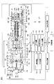
- FIG. 4 is a block diagram showing an example of the functional configuration of a controller;
- FIG. 4 is a timing chart showing an example of the operation of a controller;
- FIG. 11 is a flowchart schematically showing an example of setting processing regarding an interrupt request;
- FIG. 7 is a timing chart showing operations of a controller of an injection molding machine according to a comparative example;
- FIG. 1 An outline of an injection molding machine management system SYS according to the present embodiment will be described with reference to FIGS. 1 and 2.
- FIG. 1 An outline of an injection molding machine management system SYS according to the present embodiment will be described with reference to FIGS. 1 and 2.
- FIGS. 1 and 2 are diagrams showing an example of an injection molding machine management system according to this embodiment. Specifically, FIG. 1 is a side cross-sectional view showing the state of the injection molding machine 1 when mold opening is completed, and FIG. 2 is a side cross-sectional view showing the state of the injection molding machine 1 when the molds are closed. is drawn.
- FIGS. 1 and 2 are diagrams showing an example of an injection molding machine management system according to this embodiment. Specifically, FIG. 1 is a side cross-sectional view showing the state of the injection molding machine 1 when mold opening is completed, and FIG. 2 is a side cross-sectional view showing the state of the injection molding machine 1 when the molds are closed. is drawn.
- the X-axis, Y-axis, and Z-axis are perpendicular to each other, and the positive and negative directions of the X-axis (hereinafter simply referred to as the “X direction”) and the positive and negative directions of the Y-axis (hereinafter referred to as The “Y direction”) represents the horizontal direction, and the positive and negative directions of the Z axis (hereinafter simply “the Z direction”) represent the vertical direction.
- the injection molding machine management system SYS includes a plurality of (three in this example) injection molding machines 1 and a management device 2 .
- the number of injection molding machines 1 included in the injection molding machine management system SYS may be one.
- An injection molding machine 1 (an example of an industrial machine) performs a series of operations to obtain a molded product.
- the injection molding machine 1 is communicably connected to the management device 2 through a predetermined communication line NW. Also, the injection molding machine 1 may be communicably connected to another injection molding machine 1 through a communication line NW.
- the communication line NW may be, for example, a one-to-one communication line.
- the communication line NW may include a local network (LAN) of a facility (factory) where the injection molding machine 1 is installed.
- the local network may be constructed by wire, may be constructed by radio, or may be constructed by including both.
- the communication line NW may also include a wide area network (WAN) outside the facility (factory) where the injection molding machine 1 is installed.
- a wide area network may include, for example, a mobile communication network terminating at a base station.
- the mobile communication network may support, for example, 4G (4th Generation) including LTE (Long Term Evolution), 5G (5th Generation), and the like.
- a wide area network may also include, for example, a satellite communication network that utilizes communication satellites.
- a wide area network may also include, for example, the Internet network.
- the communication line NW may include a short-range communication line compatible with wireless communication standards such as Bluetooth (registered trademark) communication and WiFi communication.
- the injection molding machine 1 sends data regarding the operating state of the injection molding machine 1 (hereinafter referred to as "operating state data") and data regarding the production status (hereinafter referred to as “production status data”) to the management device 2 via the communication line NW.
- Send (upload) may include, for example, measurement data and control data regarding the operating state (for example, position, speed, angular velocity, acceleration, etc.) of the driven parts of the injection molding machine 1 .
- the data regarding the operating state may include, for example, measurement data and control data regarding the operating state (for example, current, voltage, etc.) of the electric drive unit of the injection molding machine 1 .
- the data regarding the operating state may include, for example, measurement data and control data regarding the operating state of the hydraulic drive unit (for example, pressure of hydraulic oil, etc.). Further, the data regarding the operating state may include data regarding the temperature state of a predetermined portion of the injection molding machine 1, for example.
- the management device 2 automatically or manually according to the input of the manager or the operator, grasps the operating state, and determines the maintenance timing of the injection molding machine 1, the operation schedule of the injection molding machine 1, and the like. can be managed.
- the data on the production status includes, for example, data on the number of molded products produced (the number of shots) from a predetermined point in time. Thereby, the management device 2 can grasp the production status of the molded product by the injection molding machine 1 .
- the injection molding machine 1 may serve as a master machine and monitor or control the operation of other injection molding machines 1 serving as slave machines through the communication line NW.
- the injection molding machine 1 (slave machine) may transmit the operating state data to the injection molding machine 1 (master machine) through the communication line NW.
- the injection molding machine 1 (master machine) can monitor the operations of other injection molding machines 1 (slave machines).
- the injection molding machine 1 (master machine) while ascertaining the operating status of the other injection molding machine 1 (slave machine) based on the operating status data, issues control commands relating to operations to other injection molding machines 1 through the communication line NW. It may be transmitted to the molding machine 1 (slave machine). This allows the injection molding machine 1 (master machine) to control the operations of other injection molding machines 1 (slave machines).
- the management device 2 is communicably connected to the injection molding machine 1 through the communication line NW, and manages the operation state, operating state, and the like of the injection molding machine 1 .
- the management device 2 may, for example, automatically manage the operating state, operational state, etc. of the injection molding machine 1 according to a predetermined rule or autonomously. Further, the management device 2 may manage the operating state, operating state, and the like of the injection molding machine 1 according to various inputs received from a user of the injection molding machine 1 such as an administrator or an operator. In other words, the management device 2 may assist the management of the operating state, operating state, and the like of the injection molding machine 1 by a user of the injection molding machine 1 such as a manager or an operator.
- the functions of the management device 2 are realized by arbitrary hardware or a combination of arbitrary hardware and software.
- the management device 2 includes a CPU (Central Processing Unit), a memory device such as RAM (Read Only Memory), a non-volatile auxiliary storage device such as ROM (Read Only Memory), and an interface device for input/output with the outside. and the like.
- the management device 2 may implement various functions by loading programs installed in the auxiliary storage device into the memory device and executing the programs on the CPU.
- the management device 2 may acquire a program to be installed in the auxiliary storage device from a predetermined recording medium through the interface device.
- Predetermined recording media include, for example, flexible discs, CDs (Compact Discs), DVDs (Digital Versatile Discs), BDs (Blu-ray (registered trademark) Discs), SD memory cards, USB (Universal Serial Bus) memories, etc.
- the management device 2 may acquire (download) a program to be installed in the auxiliary storage device from an external computer, for example, through the interface device.
- the management device 2 is, for example, a cloud server or an on-premises server installed in a remote location such as a management center outside the factory where the injection molding machine 1 is installed.
- the management device 2 is, for example, an edge server installed inside a factory where the injection molding machine 1 is installed or in a place relatively close to the factory (for example, a wireless base station or a station building near the factory).
- the management device 2 may be a terminal device (user terminal) used by a user of the injection molding machine 1 such as a manager or an operator.
- the user terminal may be a terminal device for management in the factory where the injection molding machine 1 is installed or a terminal device (user terminal) used by the user of the injection molding machine 1 .
- the terminal device for management and the user terminal may be, for example, a stationary terminal device such as a desktop PC (Personal Computer).
- the terminal device for management and the user terminal may be, for example, a portable (portable) terminal device that can be carried by a user such as an administrator or an operator of the injection molding machine 1 .
- Portable terminal devices may include, for example, smartphones, tablet terminals, laptop PCs, and the like.
- the management device 2 may grasp the operating state of the injection molding machine 1 and manage the operating state of the injection molding machine 1 based on the operating state data transmitted (uploaded) from the injection molding machine 1 . Moreover, the management device 2 may perform various diagnoses such as abnormality diagnosis of the injection molding machine 1 based on the operating state of the injection molding machine 1 grasped based on the operating state data.
- the management device 2 may manage the production status of the injection molding machine 1 based on production status data transmitted (uploaded) from the injection molding machine 1, for example.
- the management device 2 may transmit a control signal including control information (for example, information regarding various setting conditions) to the injection molding machine 1 through the communication line NW. Thereby, the management device 2 can control the operation of the injection molding machine 1 .
- control information for example, information regarding various setting conditions
- the injection molding machine 1 includes a mold clamping device 100, an ejector device 200, an injection device 300, a moving device 400, and a controller 700.
- the mold clamping device 100 performs mold closing, mold clamping, and mold opening of the mold device 10 .
- the mold clamping device 100 is, for example, a horizontal type, and the mold opening/closing direction is horizontal.
- the mold clamping device 100 has a stationary platen 110 , a movable platen 120 , a toggle support 130 , tie bars 140 , a toggle mechanism 150 , a mold clamping motor 160 , a motion converting mechanism 170 and a mold thickness adjusting mechanism 180 .
- the moving direction of the movable platen 120 when the mold is closed (the right direction in FIGS. 1 and 2) is defined as the front, and the moving direction of the movable platen 120 when the mold is opened (the direction in FIGS. The middle left direction) will be described as the rear.
- the fixed platen 110 is fixed with respect to the frame Fr.
- a fixed mold 11 is attached to the surface of the fixed platen 110 facing the movable platen 120 .
- the movable platen 120 is movable relative to the frame Fr in the mold opening/closing direction.
- a guide 101 for guiding the movable platen 120 is laid on the frame Fr.
- the movable mold 12 is attached to the surface of the movable platen 120 facing the stationary platen 110 .
- the mold device 10 includes a stationary mold 11 corresponding to the stationary platen 110 and a movable mold 12 corresponding to the movable platen 120 .
- the toggle support 130 is connected to the fixed platen 110 with a predetermined gap L, and placed on the frame Fr so as to be movable in the mold opening/closing direction.
- the toggle support 130 may be movable along guides laid on the frame Fr, for example.
- the guide for toggle support 130 may be common to guide 101 for movable platen 120 .
- the stationary platen 110 is fixed to the frame Fr, and the toggle support 130 is movable relative to the frame Fr in the mold opening/closing direction. It may be movable in the direction of opening and closing the mold.
- the tie bar 140 connects the stationary platen 110 and the toggle support 130 with a gap L in the mold opening/closing direction.
- a plurality of (for example, four) tie bars 140 may be used.
- Each tie bar 140 is parallel to the mold opening/closing direction and extends according to the mold clamping force.
- At least one tie bar 140 is provided with a tie bar strain detector 141 that detects the strain of the tie bar 140 .
- the tie bar strain detector 141 is, for example, a strain gauge.
- the tie-bar distortion detector 141 sends a signal indicating its detection result to the controller 700 .
- the detection result of the tie bar strain detector 141 is used, for example, for detecting mold clamping force.
- any mold clamping force detector that can be used to detect the mold clamping force may be used instead of or in addition to the tie bar strain detector 141 .
- the mold clamping force detector is not limited to the strain gauge type, and may be of piezoelectric type, capacitive type, hydraulic type, electromagnetic type, etc., and its mounting position is not limited to the tie bar 140 either.
- the toggle mechanism 150 is arranged between the movable platen 120 and the toggle support 130, and moves the movable platen 120 relative to the toggle support 130 in the mold opening/closing direction.
- the toggle mechanism 150 is composed of a crosshead 151, a pair of link groups, and the like. Each link group has a first link 152 and a second link 153 that are connected with pins or the like so as to be bendable and stretchable.
- the first link 152 is swingably attached to the movable platen 120 with a pin or the like
- the second link 153 is swingably attached to the toggle support 130 with a pin or the like.
- a second link 153 is attached to the crosshead 151 via a third link 154 .
- the configuration of the toggle mechanism 150 is not limited to the configuration shown in FIGS. 1 and 2. For example, although the number of nodes in each link group is five in FIGS. may be combined.
- the mold clamping motor 160 is attached to the toggle support 130 and operates the toggle mechanism 150 .
- the mold clamping motor 160 advances and retreats the crosshead 151 with respect to the toggle support 130 , thereby bending and stretching the first link 152 and the second link 153 to advance and retreat the movable platen 120 with respect to the toggle support 130 .
- the mold clamping motor 160 is directly connected to the motion conversion mechanism 170, but may be connected to the motion conversion mechanism 170 via a belt, pulley, or the like.
- the motion conversion mechanism 170 converts rotary motion of the mold clamping motor 160 into linear motion of the crosshead 151 .
- the motion converting mechanism 170 includes a threaded shaft 171 and a threaded nut 172 screwed onto the threaded shaft 171 . Balls or rollers may be interposed between the screw shaft 171 and the screw nut 172 .
- the mold clamping device 100 performs a mold closing process, a mold clamping process, a mold opening process, etc. under the control of the controller 700 .
- the mold clamping motor 160 is driven to advance the crosshead 151 at a set speed to the mold closing completion position, thereby advancing the movable platen 120 and bringing the movable mold 12 into contact with the fixed mold 11 .
- the position and speed of the crosshead 151 are detected using, for example, the mold clamping motor encoder 161 or the like.
- the mold clamping motor encoder 161 detects rotation of the mold clamping motor 160 and sends a signal indicating the detection result to the controller 700 .
- the crosshead position detector for detecting the position of the crosshead 151 and the crosshead speed detector for detecting the speed of the crosshead 151 are not limited to the mold clamping motor encoder 161, and general ones can be used.
- the movable platen position detector for detecting the position of the movable platen 120 and the movable platen speed detector for detecting the speed of the movable platen 120 are not limited to the mold clamping motor encoder 161, and general ones can be used.
- the mold clamping motor 160 is further driven to further advance the crosshead 151 from the mold closing completion position to the mold clamping position, thereby generating a mold clamping force.
- a cavity space 14 is formed between the movable mold 12 and the fixed mold 11 during mold clamping, and the injection device 300 fills the cavity space 14 with a liquid molding material.
- a molded product is obtained by solidifying the filled molding material.
- a plurality of cavity spaces 14 may be provided, in which case a plurality of molded products can be obtained at the same time.
- the mold clamping motor 160 is driven to retract the crosshead 151 at a set speed to the mold opening completion position, thereby retracting the movable platen 120 and separating the movable mold 12 from the fixed mold 11 .
- the ejector device 200 ejects the molded product from the movable mold 12 .
- the setting conditions in the mold closing process and the mold clamping process are collectively set as a series of setting conditions.
- the speed and position of the crosshead 151 in the mold closing process and the mold clamping process (including mold closing start position, speed switching position, mold closing completion position, and mold clamping position), mold clamping force, etc. are set as a series of setting conditions.
- the mold closing start position, speed switching position, mold closing completion position, and mold clamping position are arranged in this order from the rear side to the front side, and represent the start point and end point of the section in which the speed is set.
- a speed is set for each section.
- the number of speed switching positions may be one or plural.
- the speed switching position may not be set. Only one of the mold clamping position and the mold clamping force may be set.
- the setting conditions in the mold opening process are set in the same way.
- the speed and position of the crosshead 151 in the mold opening process (including the mold opening start position, speed switching position, and mold opening completion position) are collectively set as a series of setting conditions.
- the mold opening start position, the speed switching position, and the mold opening completion position are arranged in this order from the front side to the rear side, and represent the start point and end point of the section in which the speed is set.
- a speed is set for each section.
- the number of speed switching positions may be one or plural.
- the speed switching position may not be set.
- the mold opening start position and the mold closing position may be the same position.
- the mold opening completion position and the mold closing start position may be the same position.
- the speed, position, etc. of the movable platen 120 may be set instead of the speed, position, etc., of the crosshead 151 .
- the mold clamping force may be set instead of the position of the crosshead (for example, mold clamping position) or the position of the movable platen.
- the toggle mechanism 150 amplifies the driving force of the mold clamping motor 160 and transmits it to the movable platen 120 .
- the amplification factor is also called toggle factor.
- the toggle magnification changes according to the angle ⁇ between the first link 152 and the second link 153 (hereinafter referred to as “link angle”).
- the link angle ⁇ is obtained from the position of the crosshead 151 .
- the toggle magnification becomes maximum.
- the mold thickness is adjusted so that a predetermined mold clamping force can be obtained during mold clamping.
- the distance between the fixed platen 110 and the toggle support 130 is adjusted so that the link angle ⁇ of the toggle mechanism 150 becomes a predetermined angle when the movable mold 12 touches the fixed mold 11 .
- Adjust L L.
- the mold clamping device 100 has a mold thickness adjustment mechanism 180 that adjusts the mold thickness by adjusting the distance L between the fixed platen 110 and the toggle support 130 .
- the mold thickness adjusting mechanism 180 rotates a threaded shaft 181 formed at the rear end of the tie bar 140, a threaded nut 182 rotatably held by the toggle support 130, and a threaded nut 182 screwed onto the threaded shaft 181. and a mold thickness adjusting motor 183 .
- a threaded shaft 181 and a threaded nut 182 are provided for each tie bar 140 .
- Rotation of the mold thickness adjustment motor 183 may be transmitted to the plurality of screw nuts 182 via the rotation transmission portion 185 .
- Multiple screw nuts 182 can be rotated synchronously.
- the rotation transmission section 185 is composed of, for example, gears.
- a passive gear is formed on the outer circumference of each screw nut 182
- a driving gear is attached to the output shaft of the mold thickness adjusting motor 183
- an intermediate gear meshing with the plurality of passive gears and the driving gear is formed in the central portion of the toggle support 130. rotatably held.
- rotation transmission section 185 may be configured with a belt, a pulley, or the like instead of the gear.
- the operation of the mold thickness adjusting mechanism 180 is controlled by the controller 700.
- the controller 700 drives the mold thickness adjustment motor 183 to rotate the screw nut 182, thereby adjusting the position of the toggle support 130 that rotatably holds the screw nut 182 with respect to the fixed platen 110.
- the distance L from the support 130 is adjusted.
- the interval L is detected using the mold thickness adjustment motor encoder 184.
- the mold thickness adjusting motor encoder 184 detects the amount and direction of rotation of the mold thickness adjusting motor 183 and sends a signal indicating the detection results to the controller 700 .
- the detection result of the mold thickness adjustment motor encoder 184 is used for monitoring and controlling the position and interval L of the toggle support 130 .
- the toggle support position detector that detects the position of the toggle support 130 and the interval detector that detects the interval L are not limited to the mold thickness adjustment motor encoder 184, and general ones can be used.
- the mold thickness adjustment mechanism 180 adjusts the interval L by rotating one of the screw shaft 181 and the screw nut 182 that are screwed together.
- a plurality of mold thickness adjusting mechanisms 180 may be used, and a plurality of mold thickness adjusting motors 183 may be used.
- the mold clamping device 100 of this embodiment is a horizontal type in which the mold opening/closing direction is horizontal, it may be a vertical type in which the mold opening/closing direction is a vertical direction.
- the mold clamping device 100 of this embodiment has the mold clamping motor 160 as a drive source, but instead of the mold clamping motor 160, it may have a hydraulic cylinder. Further, the mold clamping device 100 may have a linear motor for mold opening and closing and an electromagnet for mold clamping.
- the ejector device 200 ejects a molded product from the mold device 10 after the molding material filled in the mold device 10 by the injection device 300 is cooled and solidified.
- the ejector device 200 has an ejector motor 210, a motion conversion mechanism 220, an ejector rod 230, and the like.
- the moving direction of the movable platen 120 when the mold is closed (the right direction in FIGS. 1 and 2) is assumed to be the front, and when the mold is opened
- the moving direction of (leftward in FIGS. 1 and 2) is defined as the rearward direction.
- the ejector motor 210 is attached to the movable platen 120.
- the ejector motor 210 is directly connected to the motion conversion mechanism 220, but may be connected to the motion conversion mechanism 220 via a belt, pulley, or the like.
- the motion conversion mechanism 220 converts rotary motion of the ejector motor 210 into linear motion of the ejector rod 230 .
- Motion converting mechanism 220 includes a threaded shaft and a threaded nut that screws onto the threaded shaft. Balls or rollers may be interposed between the screw shaft and the screw nut.
- the ejector rod 230 can move forward and backward through the through hole of the movable platen 120 .
- a front end portion of the ejector rod 230 contacts the movable member 15 which is disposed inside the movable mold 12 so as to be able to move back and forth.
- the front end of the ejector rod 230 may or may not be connected to the movable member 15 .
- the ejector device 200 performs an ejecting process under the control of the controller 700.
- the ejector motor 210 is driven to advance the ejector rod 230 from the standby position to the ejection position at a set speed, thereby advancing the movable member 15 and ejecting the molded product. Thereafter, the ejector motor 210 is driven to retract the ejector rod 230 at a set speed, thereby retracting the movable member 15 to the original standby position.
- the position and speed of the ejector rod 230 are detected using the ejector motor encoder 211, for example.
- the ejector motor encoder 211 detects rotation of the ejector motor 210 and sends a signal indicating the detection result to the controller 700 .
- the ejector rod position detector that detects the position of the ejector rod 230 and the ejector rod speed detector that detects the speed of the ejector rod 230 are not limited to the ejector motor encoder 211, and general ones can be used.
- the injection device 300 is installed on a slide base 301 that can move back and forth with respect to the frame Fr, and can move back and forth with respect to the mold device 10 .
- the injection device 300 touches the mold device 10 and fills the cavity space 14 in the mold device 10 with the molding material.
- the injection device 300 has, for example, a cylinder 310, a nozzle 320, a screw 330, a metering motor 340, an injection motor 350, a pressure detector 360, and the like.
- the direction in which the injection device 300 approaches the mold device 10 (the left direction in FIGS. 1 and 2) is defined as the front, and the direction in which the injection device 300 moves away from the mold device 10 ( 1 and 2) is referred to as the rear.
- the cylinder 310 heats the molding material supplied inside from the supply port 311 .
- the molding material includes, for example, resin.
- the molding material is formed into, for example, a pellet shape and supplied to the supply port 311 in a solid state.
- a supply port 311 is formed in the rear portion of the cylinder 310 .
- a cooler 312 such as a water-cooled cylinder is provided on the outer circumference of the rear portion of the cylinder 310 .
- a heater 313 such as a band heater and a temperature detector 314 are provided on the outer periphery of the cylinder 310 ahead of the cooler 312 .
- the cylinder 310 is divided into a plurality of zones in the axial direction of the cylinder 310 (horizontal direction in FIGS. 1 and 2).
- a heater 313 and a temperature detector 314 are provided in each zone.
- the controller 700 controls the heater 313 so that the temperature detected by the temperature detector 314 becomes the set temperature for each zone.
- the nozzle 320 is provided at the front end of the cylinder 310 and pressed against the mold device 10 .
- a heater 313 and a temperature detector 314 are provided around the nozzle 320 .
- the controller 700 controls the heater 313 so that the detected temperature of the nozzle 320 becomes the set temperature.
- the screw 330 is arranged in the cylinder 310 so as to be rotatable and advance/retreat.
- the molding material is sent forward along the helical groove of the screw 330 .
- the molding material is gradually melted by the heat from the cylinder 310 while being fed forward.
- the screw 330 is retracted as liquid molding material is fed forward of the screw 330 and accumulated at the front of the cylinder 310 . After that, when the screw 330 is advanced, the liquid molding material accumulated in front of the screw 330 is injected from the nozzle 320 and filled in the mold device 10 .
- a backflow prevention ring 331 is movably attached to the front of the screw 330 as a backflow prevention valve that prevents backflow of the molding material from the front to the rear of the screw 330 when the screw 330 is pushed forward.
- the anti-backflow ring 331 is pushed backward by the pressure of the molding material in front of the screw 330 when the screw 330 is advanced, and is relatively to the screw 330 until it reaches a closed position (see FIG. 2) that blocks the flow path of the molding material. fall back. This prevents the molding material accumulated in front of the screw 330 from flowing backward.
- the anti-backflow ring 331 is pushed forward by the pressure of the molding material sent forward along the helical groove of the screw 330 when the screw 330 is rotated, and is in an open position where the flow path of the molding material is opened. (see FIG. 1) relative to the screw 330. Thereby, the molding material is sent forward of the screw 330 .
- the anti-backflow ring 331 may be either a co-rotating type that rotates together with the screw 330 or a non-co-rotating type that does not rotate together with the screw 330 .
- the injection device 300 may have a drive source that advances and retracts the backflow prevention ring 331 with respect to the screw 330 between the open position and the closed position.
- the metering motor 340 rotates the screw 330 .
- the drive source for rotating the screw 330 is not limited to the metering motor 340, and may be, for example, a hydraulic pump.
- the injection motor 350 moves the screw 330 forward and backward. Between the injection motor 350 and the screw 330 is provided a motion conversion mechanism or the like that converts the rotary motion of the injection motor 350 into the linear motion of the screw 330 .
- the motion conversion mechanism has, for example, a screw shaft and a screw nut that screws onto the screw shaft. Balls, rollers, or the like may be provided between the screw shaft and the screw nut.
- the drive source for advancing and retreating the screw 330 is not limited to the injection motor 350, and may be, for example, a hydraulic cylinder.
- a pressure detector 360 detects pressure transmitted between the injection motor 350 and the screw 330 .
- a pressure detector 360 is provided in a force transmission path between the injection motor 350 and the screw 330 to detect the pressure acting on the pressure detector 360 .
- the pressure detector 360 sends a signal indicating its detection result to the controller 700 .
- the detection result of the pressure detector 360 is used for controlling and monitoring the pressure that the screw 330 receives from the molding material, the back pressure against the screw 330, the pressure that the screw 330 acts on the molding material, and the like.
- the injection device 300 Under the control of the controller 700, the injection device 300 performs a weighing process, a filling process, a holding pressure process, and the like.
- the weighing motor 340 is driven to rotate the screw 330 at a set number of revolutions, and the molding material is fed forward along the helical groove of the screw 330 . Along with this, the molding material is gradually melted.
- the screw 330 is retracted as liquid molding material is fed forward of the screw 330 and accumulated at the front of the cylinder 310 .
- the number of rotations of the screw 330 is detected using a metering motor encoder 341, for example.
- Weighing motor encoder 341 detects the rotation of weighing motor 340 and sends a signal indicating the detection result to controller 700 .
- the screw rotation speed detector that detects the rotation speed of the screw 330 is not limited to the weighing motor encoder 341, and a general one can be used.
- the injection motor 350 may be driven to apply a set back pressure to the screw 330 in order to limit rapid retraction of the screw 330 .
- the back pressure on screw 330 is detected using pressure detector 360, for example.
- Pressure detector 360 sends a signal to controller 700 indicating its detection result.
- the metering process is completed when the screw 330 is retracted to the metering completion position and a predetermined amount of molding material is accumulated in front of the screw 330 .
- the injection motor 350 is driven to advance the screw 330 at a set speed, and the liquid molding material accumulated in front of the screw 330 is filled into the cavity space 14 in the mold device 10 .
- the position and speed of the screw 330 are detected using an injection motor encoder 351, for example.
- the injection motor encoder 351 detects rotation of the injection motor 350 and sends a signal indicating the detection result to the controller 700 .
- V/P switching switching from the filling process to the holding pressure process
- a position where V/P switching is performed is also referred to as a V/P switching position.
- the set speed of the screw 330 may be changed according to the position of the screw 330, time, or the like.
- the screw 330 may be temporarily stopped at the set position, and then the V/P switching may be performed. Immediately before the V/P switching, instead of stopping the screw 330, the screw 330 may be moved forward or backward slowly.
- the screw position detector for detecting the position of the screw 330 and the screw speed detector for detecting the speed of the screw 330 are not limited to the injection motor encoder 351, and general ones can be used.
- the injection motor 350 is driven to push the screw 330 forward, the pressure of the molding material at the front end of the screw 330 (hereinafter also referred to as “holding pressure”) is maintained at the set pressure, and the pressure inside the cylinder 310 is maintained. The remaining molding material is pushed toward the mold device 10 . A shortage of molding material due to cooling shrinkage in the mold apparatus 10 can be replenished.
- the holding pressure is detected using a pressure detector 360, for example. Pressure detector 360 sends a signal to controller 700 indicating its detection result.
- the set value of the holding pressure may be changed according to the elapsed time from the start of the holding pressure process.
- the molding material in the cavity space 14 inside the mold device 10 is gradually cooled, and when the pressure holding process is completed, the entrance of the cavity space 14 is closed with the solidified molding material. This state is called a gate seal, and the backflow of the molding material from the cavity space 14 is prevented.
- the cooling process is started. In the cooling process, the molding material in the cavity space 14 is solidified. A weighing step may be performed during the cooling step to reduce molding cycle time.
- the injection device 300 of this embodiment is of the in-line screw system, it may be of the pre-plasticization system or the like.
- a pre-plastic injection apparatus supplies molding material melted in a plasticizing cylinder to an injection cylinder, and injects the molding material from the injection cylinder into a mold apparatus.
- a screw is arranged rotatably or rotatably and forwards and backwards within the plasticizing cylinder, and a plunger is arranged movably forwards and backwards within the injection cylinder.
- the injection device 300 of the present embodiment is a horizontal type in which the axial direction of the cylinder 310 is horizontal, but may be a vertical type in which the axial direction of the cylinder 310 is vertical.
- the mold clamping device combined with the vertical injection device 300 may be either vertical or horizontal.
- the mold clamping device combined with the horizontal injection device 300 may be horizontal or vertical.
- the moving device 400 moves the injection device 300 forward and backward with respect to the mold device 10 . Further, the moving device 400 presses the nozzle 320 against the mold device 10 to generate nozzle touch pressure.
- the moving device 400 includes a hydraulic pump 410, a motor 420 as a drive source, a hydraulic cylinder 430 as a hydraulic actuator, and the like.
- the direction in which the injection device 300 approaches the mold device 10 (the left direction in FIGS.
- the direction of separation from the mold device 10 (right direction in FIGS. 1 and 2) will be described as the rear side.
- the moving device 400 is arranged on one side of the cylinder 310 of the injection device 300 in FIGS.
- the hydraulic pump 410 has a first port 411 and a second port 412 .
- the hydraulic pump 410 is a pump that can rotate in both directions, and by switching the rotation direction of the motor 420, hydraulic fluid (for example, oil) is sucked from one of the first port 411 and the second port 412 and Discharge to generate hydraulic pressure.
- hydraulic fluid for example, oil
- the hydraulic pump 410 can also suck the hydraulic fluid from the tank and discharge the hydraulic fluid from either the first port 411 or the second port 412 .
- the motor 420 operates the hydraulic pump 410 .
- the motor 420 drives the hydraulic pump 410 with a rotational direction and rotational torque according to a control signal from the controller 700 .
- Motor 420 may be an electric motor or may be an electric servomotor.
- the hydraulic cylinder 430 has a cylinder body 431 , a piston 432 and a piston rod 433 .
- the cylinder body 431 is fixed with respect to the injection device 300 .
- the piston 432 partitions the inside of the cylinder body 431 into a front chamber 435 as a first chamber and a rear chamber 436 as a second chamber.
- Piston rod 433 is fixed relative to stationary platen 110 .
- the front chamber 435 of the hydraulic cylinder 430 is connected to the first port 411 of the hydraulic pump 410 via the first flow path 401 .
- the hydraulic fluid discharged from the first port 411 is supplied to the front chamber 435 through the first flow path 401, thereby pushing the injection device 300 forward.
- the injection device 300 is advanced and the nozzle 320 is pressed against the stationary mold 11 .
- the front chamber 435 functions as a pressure chamber that generates nozzle touch pressure of the nozzle 320 by the pressure of the hydraulic fluid supplied from the hydraulic pump 410 .
- the rear chamber 436 of the hydraulic cylinder 430 is connected to the second port 412 of the hydraulic pump 410 via the second flow path 402 .
- the hydraulic fluid discharged from the second port 412 is supplied to the rear chamber 436 of the hydraulic cylinder 430 through the second flow path 402, thereby pushing the injection device 300 rearward.
- the injection device 300 is retracted, and the nozzle 320 is separated from the stationary mold 11 .
- the moving device 400 is not limited to the configuration including the hydraulic cylinder 430 .
- an electric motor and a motion conversion mechanism that converts the rotary motion of the electric motor into the linear motion of the injection device 300 may be used.
- a controller 700 (an example of a control device) directly transmits control signals to the mold clamping device 100 , the ejector device 200 , the injection device 300 , the moving device 400 and the like, and performs various controls related to the injection molding machine 1 .
- the controller 700 may be realized by any hardware or any combination of hardware and software.
- the controller 700 is mainly composed of a computer having, for example, a CPU 701, a memory device 702, an auxiliary storage device 703, and an interface device 704 for external input/output.
- the controller 700 performs various controls by loading programs installed in the auxiliary storage device 703 into the memory device 702 and causing the CPU 701 to execute the programs.
- the controller 700 also receives external signals and outputs signals to the outside through the interface device 704 .
- the controller 700 is communicably connected to the management device 2 through the communication line NW based on the interface device 704 .
- the controller 700 may be communicably connected to (the controller 700 of) another injection molding machine 1 through the communication line NW based on the interface device 704 . Also, the controller 700 may acquire a program to be installed in itself (auxiliary storage device 703 ) from a predetermined recording medium through the interface device 704 . Predetermined recording media include, for example, flexible discs, CDs (Compact Discs), DVDs (Digital Versatile Discs), BDs (Blu-ray (registered trademark) Discs), SD memory cards, USB (Universal Serial Bus) memories, etc. . Also, the controller 700 may acquire (download) a program from an external computer (for example, the management device 2 ) through the interface device 704 .
- an external computer for example, the management device 2
- controller 700 may be realized by only one controller 700, or may be shared by a plurality of controllers (for example, the upper controller 700A and the lower controller 700B, etc.) as described later (see FIG. 2). .
- the controller 700 causes the injection molding machine 1 to repeatedly perform the mold closing process, the mold clamping process, the mold opening process, and the like, thereby repeatedly manufacturing molded products. Further, the controller 700 causes the injection device 300 to perform a weighing process, a filling process, a holding pressure process, and the like during the mold clamping process.
- a series of operations for obtaining a molded product for example, the operation from the start of the weighing process by the injection device 300 to the start of the next weighing process by the injection device 300 is also called “shot” or “molding cycle”. Also, the time required for one shot is also referred to as “molding cycle time”.
- a single molding cycle for example, consists of a weighing process, a mold closing process, a mold clamping process, a filling process, a holding pressure process, a cooling process, a mold opening process, and an ejection process in that order.
- This order is the order of the start of each process.
- the filling process, the holding pressure process, and the cooling process are performed from the start of the mold clamping process to the end of the mold clamping process. Also, the end of the mold clamping process coincides with the start of the mold opening process.
- the metering step may occur during the cooling step of the previous molding cycle, in which case the mold closing step may occur at the beginning of the molding cycle.
- the filling process may also be initiated during the mold closing process.
- the ejecting process may be initiated during the mold opening process.
- the mold opening process may be started during the metering process. This is because the molding material will not leak from the nozzle 320 as long as the on-off valve closes the flow path of the nozzle 320 even if the mold opening process is started during the metering process.
- the controller 700 is connected to an operation device 750, a display device 760, and the like.
- the operating device 750 (an example of an input device) accepts user input regarding the injection molding machine 1 and outputs a signal corresponding to the input to the controller 700 . Thereby, the user can operate the injection molding machine 1 .
- the injection molding machine 1 may be configured to accept input from the user through an external device. Thereby, the user can remotely operate the injection molding machine 1, for example. In this case, image data of an imaging device capable of imaging the operating state of the injection molding machine 1 may be transmitted to the external device. As a result, it is possible to operate the remote injection molding machine 1 while confirming the operating state of the remote injection molding machine 1 in the external device.
- the controller 700 may be capable of accepting the content of input from the user received from the management device 2 or another injection molding machine 1 through the communication line NW. Also, the controller 700 may be capable of accepting input from the user, which is received from the terminal device through the communication line NW.
- the terminal device may be, for example, a stationary terminal device such as a desktop PC, or a portable (portable) terminal device (portable terminal) such as a smartphone, tablet terminal, or laptop PC. There may be.
- the display device 760 displays various images under the control of the controller 700 .
- the display device 760 displays, for example, an operation screen regarding the injection molding machine 1 according to the operation input on the operation device 750.
- the operation screen displayed on the display device 760 is used for settings related to the injection molding machine 1 and the like.
- the settings related to the injection molding machine 1 include, for example, settings of molding conditions related to the injection molding machine 1 (specifically, input of set values).
- the settings also include, for example, settings related to selection of types of detection values of various sensors related to the injection molding machine 1 that are recorded as logging data during the molding operation.
- the setting includes, for example, display specifications of the detection values (actual values) of various sensors related to the injection molding machine 1 during the molding operation on the display device 760 (for example, the types of actual values to be displayed and the display method). etc.) are included.
- a plurality of operation screens are prepared and displayed by switching to the display device 760 or displayed in an overlapping manner. The user can perform settings (including input of setting values) related to the injection molding machine 1 by operating the operation device 750 while viewing the operation screen displayed on the display device 760 .
- the display device 760 displays, for example, under the control of the controller 700, an information screen that provides the user with various types of information according to operations on the operation screen.
- a plurality of information screens are prepared and displayed by switching to the display device 760 or displayed in an overlapping manner.
- the display device 760 displays the setting contents regarding the injection molding machine 1 (for example, the setting contents regarding the molding conditions of the injection molding machine 1).
- the display device 760 displays management information (for example, information about the operation performance of the injection molding machine 1, etc.).
- the operation device 750 and the display device 760 may be configured and integrated as a touch panel display, for example.
- the operating device 750 and the display device 760 of this embodiment are integrated, they may be provided independently. Also, a plurality of operating devices 750 may be provided.
- FIG. 3 is a diagram showing an example of the hardware configuration of the control system of the injection molding machine 1.
- FIG. 3 is a diagram showing an example of the hardware configuration of the control system of the injection molding machine 1.
- the control system of the injection molding machine 1 includes a controller 700, a driver 710, and a sensor 720.
- the controller 700 includes a CPU 701 and an FPGA (Field Programmable Gate Array) 705.
- FPGA Field Programmable Gate Array
- the CPU 701 (an example of a control processing unit) performs control processing (hereinafter referred to as "motion control processing") regarding the operation of the injection molding machine 1 based on data acquired from the driver 710 and the sensor 720 through the FPGA 705, for example.
- the motion control processing includes electric motor servo control processing.
- the CPU 701 controls the operation of the injection molding machine 1 (function of the control unit 7001 to be described later) in response to a predetermined interrupt request (hereinafter, simply “interrupt request”) periodically output from the FPGA 705 . ) to start the control process for the operation of the injection molding machine 1 .
- the CP 701 then outputs data corresponding to the control command to the driver 710 and the like through the FPGA 705 .
- the interrupt request handled in this example is a so-called hardware interrupt request output from hardware external to the CPU 701 (FPGA 705 in this example).
- the CPU 701 performs relatively high-priority processing (hereinafter referred to as “high-priority processing”) such as actuator motion control processing and servo control processing performed as motion control processing.
- High-priority processing such as actuator motion control processing and servo control processing performed as motion control processing.
- Low-priority processing perform low-priority processing.
- the CPU 701 receives an interrupt request for high-priority processing from the FPGA 705 while executing low-priority processing, the CPU 701 calls interrupt processing corresponding to the interrupt request. Then, the CPU 701 activates high-priority processing corresponding to the interrupt request by interrupt processing.
- the CPU 701 can appropriately perform the high-priority processing, which is periodically performed, at each predetermined control cycle (an example of the predetermined cycle) while performing the low-priority processing.
- the FPGA 705 (an example of a request output unit) functions as an input/output interface with the outside of the controller 700 . That is, interface device 704 includes FPGA 705 .
- the FPGA 705 receives data related to actuator control (hereinafter referred to as "control data") from the driver 710, and transmits data corresponding to control commands to the driver 710 in response to requests from the CPU 701.
- control data data related to actuator control
- the FPGA 705 also receives measurement data regarding the state of the injection molding machine 1 from the sensor 720 and transmits data corresponding to control commands regarding the measurement operation of the sensor 720 in response to requests from the CPU 701 .
- the FPGA 705 periodically outputs an interrupt request to the CPU 701 to activate a control function related to the operation of the injection molding machine 1 .
- the FPGA 705 may repeatedly set a timer that expires in each predetermined control cycle, and output an interrupt request when the timer expires.
- the driver 710 drives the actuator according to the control command from the controller 30.
- the actuator is, for example, an electric motor, and the driver 710 outputs drive current to the electric motor in accordance with control commands from the controller 30 .
- the controller 700 CPU 701
- the electric motors include, for example, the mold clamping motor 160, the mold thickness adjusting motor 183, the ejector motor 210, the metering motor 340, the injection motor 350, the motor 420, and the like.
- the sensor 720 outputs measurement data regarding the state of the injection molding machine 1.
- Sensor 720 includes, for example, an encoder capable of measuring the rotational position of the electric motor.
- Encoders include, for example, a mold clamping motor encoder 161, a mold thickness adjusting motor encoder 184, an ejector motor encoder 211, a metering motor encoder 341, and an injection motor encoder 351.
- Sensors 720 also include current sensors and voltage sensors that detect voltages and currents in the power system, including electric motor currents and voltages. Further, the sensor 720 includes various sensors (for example, the tie bar strain detector 141, the temperature detector 314, the pressure detector 360, etc.) capable of measuring force, temperature, pressure, etc. acting on a predetermined portion of the injection molding machine 1. including.
- FIG. 4 is a block diagram showing an example of the functional configuration of the controller 700. As shown in FIG. 4
- the controller 700 includes a control unit 7001, a display processing unit 7002, a storage unit 7003, a setting unit 7004, and a storage unit 7005.
- the functions of the control unit 7001 , the display processing unit 7002 , the setting unit 7004 and the like are realized by, for example, loading a program installed in the auxiliary storage device 703 into the memory device 702 and executing it on the CPU 701 .
- the functions of the storage units 7003 and 7005 are implemented by storage areas defined in the auxiliary storage device 703 of the controller 700, for example.
- the control unit 7001 controls operations of the injection molding machine 1 based on data input from the driver 710 and the sensor 720 .
- the functions of the control unit 7001 are activated and executed by interrupt requests periodically output from the FPGA 705 as described above.
- the display processing unit 7002 causes the display device 760 to display an information screen according to the input from the user received through the operation device 750 . Specifically, the display processing unit 7002 displays a screen (hereinafter referred to as “setting screen”) for the user to use the operation device 750 to set the interrupt request.
- setting screen a screen for the user to use the operation device 750 to set the interrupt request.
- the settings related to the interrupt request include settings related to the output timing of the interrupt request from the FPGA 705 (for example, the setting of the correction time T1, which will be described later). Further, the setting regarding the interrupt request includes setting regarding the timing of starting the motion control process in response to the interrupt request (for example, setting of the waiting time T2 described later).
- the storage unit 7003 stores (registers) the setting contents related to the interrupt request (for example, setting values of the correction time T1 and the waiting time T2, which will be described later).
- a setting unit 7004 performs settings related to the above-described interrupt request.
- the setting unit 7004 automatically performs settings related to an interrupt request, triggered by a predetermined input from the user received through the operation device 750 or the like, or when a condition other than the predetermined input is met.
- Conditions other than predetermined inputs include, for example, the initial startup (power-on) in the inspection process of the injection molding machine 1 before shipment from the factory, and the operation of the controller 700 of the injection molding machine 1. The first startup after initialization, etc. may be included.
- the automatic setting start condition may include the first activation after changing (updating) predetermined hardware such as an actuator of the injection molding machine 1 and predetermined software such as a program related to motion control processing.
- the setting unit 7004 may perform settings related to an interrupt request in accordance with user input received by the operation device 750 or the like, ie, input corresponding to setting details desired by the user. In other words, settings relating to interrupt requests may be made manually.
- the setting unit 7004 may limit the function of automatically or manually setting the interrupt request according to the input from the user. As a result, it is possible to prevent a situation in which the operation of the injection molding machine 1 is adversely affected due to unnecessary change of the setting regarding the interrupt request.
- the setting unit 7004 identifies the user who operates the injection molding machine 1 and determines whether or not to allow the user to set the interrupt request according to the input from the operation device 750 .
- identification information defined for each user (hereinafter referred to as “user identification information”) (for example, an ID (Identifier) for each user, image data for face authentication, etc.)
- ID an ID
- a registration information database that associates permission or non-permission may be constructed. Accordingly, the setting unit 7004 can identify the user who is using the operation device 750 based on the ID input from the operation device 750 and the image data acquired during face authentication.
- the setting unit 7004 may limit the function of setting the interrupt request when an input from the user is accepted through an external device of the injection molding machine 1 .
- the function of making settings related to interrupt requests according to inputs from some or all of the external devices may be prohibited.
- the setting for an interrupt request is changed in response to an input from a user using an external device, who is in a situation where it is relatively difficult to grasp the operation state of the injection molding machine 1, the injection molding machine 1 This is because there is a possibility that countermeasures will be delayed when the operation of 1 is adversely affected.
- settings relating to interrupt requests can be changed according to an input through an external device, there is a possibility that a problem will arise from the viewpoint of security.
- Various data used by the setting unit 7004 are stored in the storage unit 7005 .
- the above-described registration information database may be constructed in the storage unit 7005 .
- controller 700 [Specific example of controller operation] Next, a specific example of the operation of controller 700 will be described with reference to FIG.
- FIG. 5 is a timing chart showing an example of the operation of controller 700. As shown in FIG. Specifically, FIG. 5 shows "data output”, “data preparation”, “interrupt timer”, 4 is a timing chart showing respective states of "interrupt processing” and "motion control processing";
- Data output represents the output state of data (for example, control data to the driver 710) as a result of motion control processing by the controller 700 (control unit 7001).
- Data preparation is data used for motion control processing by the controller 700 (control unit 7001) (for example, data received from the driver 710 and sensor 720, output data from the motion control processing in the previous control cycle, etc.). ) represents the ready state. Data used for motion control processing is stored in the internal memory of the FPGA 705, and by accessing the internal memory of the FPGA 705, the CPU 701 can use this data to execute motion control processing.
- Interrupt timer represents the operating state of the timer set for the FPGA 705 to output an interrupt request.
- the rising edge of the operating state of the timer in the figure represents the start of the timer, and the falling edge thereof represents the end of the timer. Then, the interrupt request is output with the expiration of the timer as a trigger.
- Interrupt processing indicates the implementation state (whether or not to implement) of preprocessing (interrupt processing) for interrupting and executing motion control processing in low priority processing in response to an interrupt request output from the FPGA 705. show.
- Motion control processing represents the execution state (whether or not to execute) of the motion control processing executed by the CPU 701.
- the interrupt request output timing is changed from the initial state, ie, the predetermined reference state, as the setting regarding the interrupt request.
- the reference state means a state in which the timing of the interrupt request is matched with the reference timing that triggers the start of motion control processing.
- the reference state means a state in which the timing of the interrupt request is adjusted to the timing at which the data used in the motion control processing is assumed to be ready.
- the timing of the interrupt request is advanced by the correction time T1 from the reference state. More specifically, the termination timing of the timer for the interrupt request of the FPGA 705 is advanced by the correction time T1 from the reference state.
- the timer ends before data preparation is completed, and the FPGA 705 outputs an interrupt request to the CPU 701 (time t11).
- the FPGA 705 When the FPGA 705 outputs the interrupt request, it starts the next timer (around time t12).
- the CPU 701 starts interrupt processing in response to the interrupt request output from the FPGA 705 (time t12).
- the initial state is, for example, a state in which the start timing of motion control is adjusted to the completion of interrupt processing. That is, in the initial state, the motion control process is started immediately after the interrupt process is completed.
- the timing for starting the motion control process is changed to the timing at which the interrupt process is completed or the timing at which the waiting time T2 has elapsed from the start of the interrupt process, whichever is later.
- the interrupt processing this time takes a relatively long time, and the timing at which the waiting time T2 elapses and the timing at which the interrupt processing ends are approximately the same timing (time t13). Therefore, the CPU 701 starts motion control processing at that timing.
- the waiting time T2 is set so that the timing of starting the motion control processing is substantially the same as the timing when the preparation of data used for the motion control processing in the FPGA 705 is assumed to be completed (for example, immediately after that). is set to Therefore, the motion control process is started immediately after the data is ready.
- This allows the CPU 701 to start motion control processing after the latest data is ready. Therefore, the CPU 701 can appropriately control the operation of the injection molding machine 1 .
- the controller 700 can easily ensure real-time performance regarding motion control processing.
- the waiting time T2 may be set arbitrarily as long as the motion control process is started after the timing assumed to complete the preparation of the data used in the motion control process.
- the CPU 701 After the motion control processing in the current control cycle is completed, the CPU 701 outputs data regarding the execution result of the motion control processing in the current control cycle (time t14). The output data is stored (written) in the internal memory of the FPGA 705, for example.
- the FPGA 705 After completion of data output by the CPU 701, when the timer started after output of the previous interrupt request expires, the FPGA 705 outputs an interrupt request to the CPU 701 (time t15).
- the CPU 701 starts interrupt processing in response to the interrupt request output from the FPGA 705 (time t16).
- the interrupt processing this time is completed in a relatively short time (time t17). Therefore, after the completion of interrupt processing, the CPU 701 waits for the waiting time T2 to elapse from the start of the interrupt processing, and then starts the motion control processing (time t18). As a result, even if the interrupt process ends relatively early, the CPU 701 can perform the motion control process after preparation of the data used in the motion control process is completed by appropriately setting the waiting time T2. Processing can begin.
- the CPU 701 After completing the motion control processing in the current control cycle, the CPU 701 outputs data regarding the execution result of the motion control processing in the current control cycle (time t19).
- the controller 700 can substantially match the output timing (required data output time T0) of the data related to the execution result of the motion control process based on the completion of preparation of the data used in the motion control process. Therefore, the controller 700 can more appropriately ensure real-time performance regarding motion control processing.
- the FPGA 705 may output to the CPU 701 a notification that data used for motion control processing is ready.
- the timing of starting the motion control process is changed to the timing of completion of the interrupt process or the timing of completion of data preparation, whichever is later. This allows the controller 700 to start motion control processing when the data is ready.
- FIG. 6 is a flowchart schematically showing an example of setting processing regarding an interrupt request by the controller 700.
- FIG. This flowchart may be executed, for example, when a predetermined input from the user is received through the operation device 750 or the like. Also, this flowchart may be executed, for example, when the above-described automatic setting start condition is satisfied.
- step S102 the setting unit 7004 determines whether or not a function for automatically setting interrupt requests (hereinafter referred to as "automatic setting function”) is enabled.
- the automatic setting function may be, for example, a mode that can be selected by the user through the operation device 750 or the like. Further, when the above-described automatic setting start condition is satisfied, the automatic setting start condition may be set to a valid state as an initial state, or the initial state may be set according to the specifications of each delivery destination of the injection molding machine 1. , a valid state or an invalid state may be set.
- step S104 the setting unit 7004 proceeds to step S104, and if the automatic setting function is not valid, the current flowchart ends.
- step S104 the setting unit 7004 actually operates the function of the control unit 7001, and calculates the required time from the output (occurrence) of the interrupt request to the start of motion control processing in the initial state of the correction time T1 and the waiting time T2. measure time. That is, the setting unit 7004 measures the time required from the output of the interrupt request to the completion of the interrupt process.
- step S104 When the processing of step S104 is completed, the controller 700 proceeds to step S106.
- step S106 the setting unit 7004 determines whether or not the number of measurements of the required time from the output (occurrence) of the interrupt request to the start of motion control processing is equal to or greater than the set number of times Nth (an integer equal to or greater than 1). If the number of times of measurement is not equal to or greater than the set number of times Nth, the setting unit 7004 returns to step S104 and repeats the processes of steps S104 and S106 in the control cycle of the next motion control process. On the other hand, when the number of times of measurement is equal to or greater than the set number of times Nth, the setting unit 7004 actually stops the operation of the function of the control unit 7001, and proceeds to step S108.
- the setting unit 7004 sets the correction time T1 and the waiting time T2 based on the measurement result of the set number of times Nth.
- the setting unit 7004 may set the correction time T1 based on the maximum value among the measurement results of the set number of times Nth. Specifically, the setting unit 7004 may set the maximum value or more of the measurement results of the set number of times Nth as the correction time T1. As a result, the interrupt processing can be terminated before the timing when the preparation of the data used for the motion control processing is assumed to be completed. Therefore, by appropriately setting the waiting time T2, the controller 700 can start motion control processing in accordance with the completion of data preparation. Specifically, the setting unit 7004 may set the expected required time from the output of the interrupt request to the start of the interrupt process to be equal to or greater than the value obtained by subtracting the determined correction time T1.
- the setting unit 7004 may set the correction time T1 and the waiting time T2 based on an average value or the like of the measurement results of the set number of times Nth.
- step S108 the controller 700 ends the process of this flowchart.
- the controller 700 can set the correction time T1 and the waiting time T2 based on the actual required time from the output of the interrupt request to the completion of the interrupt processing.
- FIG. 7 is a diagram showing an example of a setting screen displayed on the display device 760 (setting screen 70).
- a similar setting screen may be displayed on the management device 2 external to the injection molding machine 1 or the terminal device described above, which is communicably connected through the communication line NW.
- a user of the injection molding machine 1 such as a manager or an operator, can check the setting contents related to the interrupt request or perform settings related to the interrupt request through the management device 2 or the above-described terminal device.
- the setting screen 70 includes a processing content display portion 71, a correction time display portion 72, a waiting time display portion 73, and icons 74-77.
- the processing flow from the output of the interrupt request to the start of the motion control processing is drawn as a timing chart, and the time intervals corresponding to the correction time T1 and the waiting time T2 are displayed.
- the user can grasp the flow of processing from the output of the interrupt request to the start of the motion control processing, and specifically check the time intervals corresponding to the correction time T1 and the waiting time T2 in the flow. can be done.
- the correction time display section 72 displays the current set value of the correction time T1.
- the current set value of the waiting time T2 is displayed in the waiting time display section 73.
- the icon 74 indicates whether the automatic setting function is enabled or disabled, that is, whether the setting regarding the interrupt request can be automatically performed or whether the setting regarding the interrupt request can be manually performed. In this example, a state in which the automatic correction function is enabled is displayed.
- the icon 75 is an operation target for starting the setting of the correction time T1 and the waiting time T2 by the automatic setting function.
- the user can cause the controller 700 to automatically set the correction time T1 and the waiting time T2 based on the above-described flowchart of FIG.
- the icon 76 is an operation target for switching to a control state in which settings related to interrupt requests can be manually made.
- the icon 76 is operated through the operation device 750 or the like, it may be possible to input values into the input boxes of the correction time T1 and the waiting time T2 in the correction time display section 72 and the waiting time display section 73, respectively.
- the icons 75 and 76 are displayed in an inoperable state (for example, grayed out state). may be displayed. Also, the values that can be input for the correction time T1 and the waiting time T2 may naturally be limited in advance to a range that does not adversely affect the motion control processing.
- the icon 77 is an operation target for returning to a predetermined screen (for example, the home screen).
- the user can confirm the setting contents (setting values of the correction time T1 and the waiting time T2) regarding the interrupt request through the setting screen 70 .
- the user can make the controller 700 perform settings (changes) regarding interrupt requests through the setting screen 70 using an automatic setting function or manually.
- FIG. 8 is a timing chart showing the operation of the controller of the injection molding machine according to the comparative example.
- description will be made using the same names for configurations similar to those of the controller 700 in the comparative example without attaching reference numerals.
- the timer is set to end at the timing when the preparation of the data used for motion control processing in the FPGA is assumed to be completed.
- the FPGA outputs an interrupt request when the timer expires (time t21).
- the CPU starts interrupt processing in response to the interrupt request output from the FPGA (time t22).
- the CPU outputs data regarding the execution result of the motion control process in the current control cycle (time t24).
- the output data is stored (written) in the internal memory of the FPGA, for example.
- the FPGA After the data output by the CPU is completed, when the timer started after the output of the previous interrupt request expires, the FPGA sends an interrupt request to the CPU in accordance with the completion of preparation of the data used for motion control processing, as in the previous time. It is being output (time t25).
- the CPU 701 starts interrupt processing in response to the interrupt request output from the FPGA (time t26).
- interrupt processing When the interrupt processing is completed, the CPU 701 starts motion control processing (time t27). In the current control cycle, interrupt processing takes a relatively longer time than in the previous control cycle (dotted line in the figure). This is because the time required for interrupt processing may vary depending on the overhead of interrupt processing, cache hits in interrupt processing, and the like.
- the CPU 701 After completing the motion control processing in the current control cycle, the CPU 701 outputs data regarding the execution result of the motion control processing in the current control cycle (time t28).
- the output timing of the data related to the execution result of the motion control process (required data output time T0c), which is based on the completion of preparation of the data used in the motion control process, depends on the required time of the interrupt process. In other words, if the time required for interrupt processing becomes relatively long, the start timing of motion control processing relative to the completion of preparation of the data required for motion control processing becomes relatively late, and real-time motion control processing becomes difficult. impact may occur.
- the controller 700 outputs an interrupt request before the occurrence of a trigger that serves as a reference for starting motion control processing (hereinafter referred to as a “start trigger”), and controls after the occurrence of the trigger.
- start trigger may be the readyness of data required for motion control processing.
- the controller 700 can execute interrupt processing before the start trigger. Therefore, it is possible to suppress the influence on the start timing of the motion control process due to variations in the required time of the interrupt process. Also, even if the interrupt process ends at a relatively early timing, the motion control process is started after the start trigger, so the motion control process is not executed before the start trigger. Therefore, in the injection molding machine 1, the controller 700 can more appropriately realize real-time control processing regarding its operation.
- the output timing of the interrupt request (correction time T1) and the start timing of the other control processing (waiting time T2) may be appropriately set in accordance with the trigger that serves as the reference for starting the other control processing.
- the motion control processing may be started after the trigger is generated.
- the controller 700 can start motion control processing in accordance with the generation of the start trigger. Therefore, in the injection molding machine 1, the controller 700 can more appropriately realize the real-time nature of its operation.
- the controller 700 may start motion control processing after a predetermined time (waiting time T2) has elapsed from the start of interrupt processing based on an interrupt request.
- the controller 700 can start the motion control process after the start trigger is generated by appropriately setting the waiting time T2.
- the controller 700 measures the time required from the output of the interrupt request to the completion of the interrupt processing multiple times, and based on the measurement results, the output timing (correction time T1) and the waiting time T2 of the interrupt request. can be set.
- the controller 700 more appropriately sets the interrupt request output timing (correction time T1) and the waiting time T2 in consideration of the actual variation in the time required from the output of the interrupt request to the completion of the interrupt processing. be able to.
- the correction time T1 is set to a relatively small value so that the timing of completion of interrupt processing always comes after the start trigger (completion of data preparation). Because you can.
- the display device 760 displays the settings related to the start of the motion control process based on the output of the interrupt request, including the output timing of the interrupt request, when a predetermined input is received by the operation device 750. you can
- the injection molding machine 1 allows the user to confirm the setting details (for example, the setting details of the correction time T1 and the waiting time T2) regarding the start of the motion control process based on the output of the interrupt request.
- the contents regarding the timing of outputting the interrupt request and the timing of starting the control process based on the interrupt request in the above-described embodiment may be adopted for controlling the operation of other control machines.
- Other machines are, for example, industrial machines and industrial robots used in factories.
- Injection molding machine (industrial machine) 2 management device 100 mold clamping device 200 ejector device 300 injection device 400 moving device 700 controller (control device) 701 CPU (control processing unit) 702 memory device 703 auxiliary storage device 704 interface device 705 FPGA (request output unit) 710 driver 720 sensor 750 operating device (input device) 760 display device 7001 control unit 7002 display processing unit 7003 storage unit 7004 setting unit 7005 storage unit SYS injection molding machine management system
Landscapes
- Engineering & Computer Science (AREA)
- Manufacturing & Machinery (AREA)
- Mechanical Engineering (AREA)
- Injection Moulding Of Plastics Or The Like (AREA)
- Moulds For Moulding Plastics Or The Like (AREA)
Abstract
Description
金型装置を型締する型締装置と、
前記型締装置により型締された前記金型装置に成形材料を充填する射出装置と、
前記射出装置により充填された成形材料が冷却固化した後、前記金型装置から成形品を取り出すエジェクタ装置と、
所定周期ごとに割り込み要求を出力し、前記割り込み要求に応じて、射出成形機の動作に関する制御処理を行う制御装置と、を備え、
前記制御装置は、前記制御処理の開始の基準となるトリガの発生より前に前記割り込み要求を出力し、前記トリガの発生の以後に前記制御処理を開始する、
射出成形機が提供される。
所定周期ごとに割り込み要求を出力する割り込み要求出力部と、
前記割り込み要求に応じて、産業機械の動作に関する制御処理を行う制御処理部と、を備え、
前記割り込み要求出力部は、前記制御処理の開始の基準となるトリガの発生より前に前記割り込み要求を出力し、
前記制御処理部は、前記トリガの発生の以後に前記制御処理を開始する、
コントローラが提供される。
まず、図1、図2を参照して、本実施形態に係る射出成形機管理システムSYSの概要について説明する。
射出成形機1(産業機械の一例)は、成形品を得るための一連の動作を行う。
管理装置2は、通信回線NWを通じて、射出成形機1と通信可能に接続され、射出成形機1の動作状態や運用状態等を管理する。管理装置2は、例えば、所定のルールに沿って、或いは、自律的に、射出成形機1の動作状態や運用状態等を自動で管理してよい。また、管理装置2は、例えば、管理者や作業者等の射出成形機1のユーザから受け付けられる各種の入力に応じて、射出成形機1の動作状態や運用状態等を管理してもよい。つまり、管理装置2は、管理者や作業者等の射出成形機1のユーザによる射出成形機1の動作状態や運用状態等の管理を支援してもよい。
次に、引き続き、図1、図2を参照して、射出成形機の構成について説明する。
型締装置100は、金型装置10の型閉、型締、及び型開を行う。型締装置100は、例えば、横型であって、型開閉方向が水平方向である。型締装置100は、固定プラテン110、可動プラテン120、トグルサポート130、タイバー140、トグル機構150、型締モータ160、運動変換機構170、及び型厚調整機構180を有する。
エジェクタ装置200は、射出装置300により金型装置10に充填された成形材料が冷却固化した後、金型装置10から成形品を突き出す。エジェクタ装置200は、エジェクタモータ210、運動変換機構220、及びエジェクタロッド230等を有する。
射出装置300は、フレームFrに対し進退自在なスライドベース301に設置され、金型装置10に対し進退自在とされる。射出装置300は、金型装置10にタッチし、金型装置10内のキャビティ空間14に成形材料を充填する。射出装置300は、例えば、シリンダ310、ノズル320、スクリュ330、計量モータ340、射出モータ350、及び圧力検出器360等を有する。
移動装置400は、金型装置10に対し射出装置300を進退させる。また、移動装置400は、金型装置10に対しノズル320を押し付け、ノズルタッチ圧力を生じさせる。移動装置400は、液圧ポンプ410、駆動源としてのモータ420、及び液圧アクチュエータとしての液圧シリンダ430等を有する。
コントローラ700(制御装置の一例)は、型締装置100、エジェクタ装置200、射出装置300、及び移動装置400等に直接的に制御信号を送信し、射出成形機1に関する各種制御を行う。
次に、図3を参照して、射出成形機1の制御系のハードウェア構成について説明する。
次に、図4を参照して、コントローラ700の機能構成について説明する。
次に、図5を参照して、コントローラ700の動作の具体例について説明する。
"割り込み処理"、及び"モーション制御処理"のそれぞれの状態を表すタイミングチャートである。
次に、図6を参照して、コントローラ700による割り込み要求に関する設定処理について説明する。
次に、図7を参照して、割り込み要求に関する設定のための設定画面について説明する。
次に、図8を参照して、本実形態に係る射出成形機1(コントローラ700)の作用について説明する。
以上、射出成形機管理システムSYS等の実施形態について説明したが、本開示は上述の実施形態等に限定されるものではなく、特許請求の範囲に記載された要旨の範囲内において、種々の変形、変更が可能である。
2 管理装置
100 型締装置
200 エジェクタ装置
300 射出装置
400 移動装置
700 コントローラ(制御装置)
701 CPU(制御処理部)
702 メモリ装置
703 補助記憶装置
704 インタフェース装置
705 FPGA(要求出力部)
710 ドライバ
720 センサ
750 操作装置(入力装置)
760 表示装置
7001 制御部
7002 表示処理部
7003 記憶部
7004 設定部
7005 記憶部
SYS 射出成形機管理システム
Claims (8)
- 金型装置を型締する型締装置と、
前記型締装置により型締された前記金型装置に成形材料を充填する射出装置と、
前記射出装置により充填された成形材料が冷却固化した後、前記金型装置から成形品を取り出すエジェクタ装置と、
所定周期ごとに割り込み要求を出力し、前記割り込み要求に応じて、射出成形機の動作に関する制御処理を行う制御装置と、を備え、
前記制御装置は、前記制御処理の開始の基準となるトリガの発生より前に前記割り込み要求を出力し、前記トリガの発生の以後に前記制御処理を開始する、
射出成形機。 - 前記トリガは、前記制御処理に必要なデータの準備完了である、
請求項1に記載の射出成形機。 - 前記制御装置は、前記割り込み要求の出力後、前記トリガの発生前に前記制御処理の開始準備が完了した場合、前記トリガの発生を待って、前記制御処理を開始する、
請求項1又は2に記載の射出成形機。 - 前記制御装置は、前記割り込み要求に基づく割り込み処理の開始から所定時間の経過後に、前記制御処理を開始する、
請求項1乃至3の何れか一項に記載の射出成形機。 - 前記制御装置は、前記割り込み要求の出力から前記割り込み要求に基づく割り込み処理の完了までに要する時間を複数回測定し、その測定結果に基づき、前記割り込み要求の出力タイミングを設定する、
請求項1乃至3の何れか一項に記載の射出成形機。 - 前記制御装置は、前記割り込み要求の出力から前記割り込み要求に基づく割り込み処理の完了までに要する時間を複数回測定し、その測定結果に基づき、前記割り込み要求の出力タイミング及び前記所定時間を設定する、
請求項4に記載の射出成形機。 - ユーザの入力を受け付ける入力装置と、
前記入力装置により所定の入力が受け付けられる場合に、前記割り込み要求の出力タイミングを含む、前記割り込み要求の出力に基づく前記制御処理の開始に関する設定内容を表示する表示装置と、を備える、
請求項1乃至6の何れか一項に記載の射出成形機。 - 所定周期ごとに割り込み要求を出力する割り込み要求出力部と、
前記割り込み要求に応じて、産業機械の動作に関する制御処理を行う制御処理部と、を備え、
前記割り込み要求出力部は、前記制御処理の開始の基準となるトリガの発生より前に前記割り込み要求を出力し、
前記制御処理部は、前記トリガの発生の以後に前記制御処理を開始する、
コントローラ。
Priority Applications (3)
| Application Number | Priority Date | Filing Date | Title |
|---|---|---|---|
| JP2023511416A JP7831722B2 (ja) | 2021-03-31 | 2022-03-29 | 射出成形機、コントローラ |
| CN202280008208.0A CN116669883A (zh) | 2021-03-31 | 2022-03-29 | 注射成型机及控制器 |
| DE112022001937.9T DE112022001937B8 (de) | 2021-03-31 | 2022-03-29 | Spritzgiessmaschine und steuerung |
Applications Claiming Priority (2)
| Application Number | Priority Date | Filing Date | Title |
|---|---|---|---|
| JP2021-060659 | 2021-03-31 | ||
| JP2021060659 | 2021-03-31 |
Publications (1)
| Publication Number | Publication Date |
|---|---|
| WO2022210773A1 true WO2022210773A1 (ja) | 2022-10-06 |
Family
ID=83459483
Family Applications (1)
| Application Number | Title | Priority Date | Filing Date |
|---|---|---|---|
| PCT/JP2022/015664 Ceased WO2022210773A1 (ja) | 2021-03-31 | 2022-03-29 | 射出成形機、コントローラ |
Country Status (4)
| Country | Link |
|---|---|
| JP (1) | JP7831722B2 (ja) |
| CN (1) | CN116669883A (ja) |
| DE (1) | DE112022001937B8 (ja) |
| WO (1) | WO2022210773A1 (ja) |
Citations (4)
| Publication number | Priority date | Publication date | Assignee | Title |
|---|---|---|---|---|
| JPH11105092A (ja) * | 1997-10-06 | 1999-04-20 | Meiki Co Ltd | 多段制御の切換方法 |
| JP2010000717A (ja) * | 2008-06-20 | 2010-01-07 | Toyo Mach & Metal Co Ltd | 成形機管理装置及び成形機管理方法 |
| WO2020122187A1 (ja) * | 2018-12-12 | 2020-06-18 | 住友重機械工業株式会社 | 射出成形機、コントローラ |
| WO2020122186A1 (ja) * | 2018-12-12 | 2020-06-18 | 住友重機械工業株式会社 | 射出成形機、射出成形システム、コントローラ |
Family Cites Families (7)
| Publication number | Priority date | Publication date | Assignee | Title |
|---|---|---|---|---|
| JPH0210717A (ja) * | 1988-06-29 | 1990-01-16 | Nikon Corp | アライメント装置 |
| US5456870A (en) | 1994-05-20 | 1995-10-10 | Van Dorn Demag Corporation | Barrel temperature state controller for injection molding machine |
| DE19847740C1 (de) * | 1998-10-16 | 2000-03-23 | Richard Herbst | Verfahren zum Steuern eines Bewegungsablaufs eines bewegbaren Bauteils einer Kunststoff-Spritzgießmaschine |
| JP2006073027A (ja) | 2005-09-30 | 2006-03-16 | Toshiba Mach Co Ltd | 産業用機器制御方法および産業用機器 |
| JP6404081B2 (ja) * | 2014-10-22 | 2018-10-10 | 住友重機械工業株式会社 | 射出成形機 |
| CN107379463B (zh) * | 2017-05-31 | 2019-04-09 | 深圳市亚启科技有限公司 | 一种注塑机开模终点位置控制方法及系统 |
| JP7335121B2 (ja) | 2019-10-03 | 2023-08-29 | ヤフー株式会社 | 提案装置、提案方法及び提案プログラム |
-
2022
- 2022-03-29 WO PCT/JP2022/015664 patent/WO2022210773A1/ja not_active Ceased
- 2022-03-29 JP JP2023511416A patent/JP7831722B2/ja active Active
- 2022-03-29 DE DE112022001937.9T patent/DE112022001937B8/de active Active
- 2022-03-29 CN CN202280008208.0A patent/CN116669883A/zh active Pending
Patent Citations (4)
| Publication number | Priority date | Publication date | Assignee | Title |
|---|---|---|---|---|
| JPH11105092A (ja) * | 1997-10-06 | 1999-04-20 | Meiki Co Ltd | 多段制御の切換方法 |
| JP2010000717A (ja) * | 2008-06-20 | 2010-01-07 | Toyo Mach & Metal Co Ltd | 成形機管理装置及び成形機管理方法 |
| WO2020122187A1 (ja) * | 2018-12-12 | 2020-06-18 | 住友重機械工業株式会社 | 射出成形機、コントローラ |
| WO2020122186A1 (ja) * | 2018-12-12 | 2020-06-18 | 住友重機械工業株式会社 | 射出成形機、射出成形システム、コントローラ |
Also Published As
| Publication number | Publication date |
|---|---|
| JP7831722B2 (ja) | 2026-03-17 |
| JPWO2022210773A1 (ja) | 2022-10-06 |
| DE112022001937B8 (de) | 2025-09-04 |
| DE112022001937T5 (de) | 2024-01-25 |
| CN116669883A (zh) | 2023-08-29 |
| DE112022001937B4 (de) | 2025-05-28 |
Similar Documents
| Publication | Publication Date | Title |
|---|---|---|
| JPWO2018159726A1 (ja) | 補正装置、射出成形システムおよび補正方法 | |
| CN113165062B (zh) | 注射成型机、注射成型系统 | |
| US9162386B2 (en) | Controller for an injection molding machine | |
| US11992987B2 (en) | Injection molding machine, management system, and controller | |
| CN113195196A (zh) | 注射成型机、注射成型系统、控制器 | |
| EP3957460B1 (en) | Injection molding machine system and controller for industrial machinery | |
| JP2017136791A (ja) | 射出成形機 | |
| JP7831722B2 (ja) | 射出成形機、コントローラ | |
| CN113165244A (zh) | 注射成型机、控制器 | |
| JP2016083777A (ja) | 射出成形機 | |
| CN114616082B (zh) | 注射成型机及控制器 | |
| JP7794537B2 (ja) | 射出成形機、射出成形機システム、管理装置 | |
| JP7616764B2 (ja) | 射出成形機 | |
| JP7652503B2 (ja) | 射出成形機、コントローラ | |
| JP7547713B2 (ja) | 射出成形機システム、射出成形機 | |
| JP7479904B2 (ja) | 射出成形機システム、射出成形機、情報処理装置 | |
| JP7632976B2 (ja) | 射出成形機、産業機械のコントローラ | |
| CN113459400A (zh) | 注射成型机、工业用机械 | |
| JP6629112B2 (ja) | 射出装置 | |
| JP7391737B2 (ja) | 射出成形機、産業機械 | |
| JP2025101049A (ja) | 射出成形機の制御装置、射出成形機、及び射出成形機の制御方法 | |
| JP2021160223A (ja) | 産業機械用制御装置、射出成形機 | |
| CN118769492A (zh) | 注射成型机的管理装置、注射成型机及注射成型机的管理方法 | |
| CN116001227A (zh) | 工业机械的控制装置及工业机械的控制方法 | |
| JP2023028046A (ja) | 射出成形機、産業機械のコントローラ |
Legal Events
| Date | Code | Title | Description |
|---|---|---|---|
| 121 | Ep: the epo has been informed by wipo that ep was designated in this application |
Ref document number: 22780984 Country of ref document: EP Kind code of ref document: A1 |
|
| ENP | Entry into the national phase |
Ref document number: 2023511416 Country of ref document: JP Kind code of ref document: A |
|
| WWE | Wipo information: entry into national phase |
Ref document number: 202280008208.0 Country of ref document: CN |
|
| WWE | Wipo information: entry into national phase |
Ref document number: 112022001937 Country of ref document: DE |
|
| 122 | Ep: pct application non-entry in european phase |
Ref document number: 22780984 Country of ref document: EP Kind code of ref document: A1 |
|
| WWG | Wipo information: grant in national office |
Ref document number: 112022001937 Country of ref document: DE |