WO2022210695A1 - ダイヤモンド光磁気センサ - Google Patents
ダイヤモンド光磁気センサ Download PDFInfo
- Publication number
- WO2022210695A1 WO2022210695A1 PCT/JP2022/015393 JP2022015393W WO2022210695A1 WO 2022210695 A1 WO2022210695 A1 WO 2022210695A1 JP 2022015393 W JP2022015393 W JP 2022015393W WO 2022210695 A1 WO2022210695 A1 WO 2022210695A1
- Authority
- WO
- WIPO (PCT)
- Prior art keywords
- diamond
- magneto
- optical sensor
- excitation light
- optical
- Prior art date
- Legal status (The legal status is an assumption and is not a legal conclusion. Google has not performed a legal analysis and makes no representation as to the accuracy of the status listed.)
- Ceased
Links
Images











Classifications
-
- G—PHYSICS
- G01—MEASURING; TESTING
- G01R—MEASURING ELECTRIC VARIABLES; MEASURING MAGNETIC VARIABLES
- G01R33/00—Arrangements or instruments for measuring magnetic variables
- G01R33/02—Measuring direction or magnitude of magnetic fields or magnetic flux
- G01R33/032—Measuring direction or magnitude of magnetic fields or magnetic flux using magneto-optic devices, e.g. Faraday or Cotton-Mouton effect
-
- G—PHYSICS
- G01—MEASURING; TESTING
- G01R—MEASURING ELECTRIC VARIABLES; MEASURING MAGNETIC VARIABLES
- G01R33/00—Arrangements or instruments for measuring magnetic variables
- G01R33/20—Arrangements or instruments for measuring magnetic variables involving magnetic resonance
- G01R33/24—Arrangements or instruments for measuring magnetic variables involving magnetic resonance for measuring direction or magnitude of magnetic fields or magnetic flux
- G01R33/26—Arrangements or instruments for measuring magnetic variables involving magnetic resonance for measuring direction or magnitude of magnetic fields or magnetic flux using optical pumping
-
- G—PHYSICS
- G01—MEASURING; TESTING
- G01R—MEASURING ELECTRIC VARIABLES; MEASURING MAGNETIC VARIABLES
- G01R33/00—Arrangements or instruments for measuring magnetic variables
- G01R33/0047—Housings or packaging of magnetic sensors ; Holders
-
- G—PHYSICS
- G01—MEASURING; TESTING
- G01R—MEASURING ELECTRIC VARIABLES; MEASURING MAGNETIC VARIABLES
- G01R33/00—Arrangements or instruments for measuring magnetic variables
- G01R33/20—Arrangements or instruments for measuring magnetic variables involving magnetic resonance
- G01R33/28—Details of apparatus provided for in groups G01R33/44 - G01R33/64
- G01R33/32—Excitation or detection systems, e.g. using radio frequency signals
- G01R33/323—Detection of MR without the use of RF or microwaves, e.g. force-detected MR, thermally detected MR, MR detection via electrical conductivity, optically detected MR
Definitions
- This disclosure relates to a diamond magneto-optical sensor.
- This application claims priority based on Japanese application No. 2021-059798 filed on March 31, 2021, and incorporates all the descriptions described in the Japanese application.
- NV center A magneto-optical sensor using the NV center of diamond (hereinafter referred to as NV center) is known.
- the NV center is excited with a wavelength of 532 nm (ie, green light), it emits fluorescence with a wavelength of 637 nm (ie, red light).
- the emission intensity of fluorescence changes depending on the spin state, and the spin state changes due to magnetic resonance caused by a magnetic field applied to the NV center and microwaves or radio waves. Therefore, it can be used as a diamond magneto-optical sensor.
- a diamond magneto-optical sensor consists of a diamond substrate containing NV centers, an optical system that transmits excitation light from a light source and irradiates the NV centers, and an optical system that collects fluorescence from the NV centers and transmits them to a photodetector. It consists of a system and a waveguide that transmits microwaves from a power supply and irradiates them to the NV center.
- Non-Patent Document 1 discloses a configuration in which a diamond sensor is mounted on a coplanar waveguide and microwaves are irradiated.
- the shape of the diamond substrate is a rectangular parallelepiped, the excitation light is irradiated from the side of the diamond substrate, and the fluorescent light is collected from the top of the diamond substrate.
- a diamond magneto-optical sensor includes a diamond having a color center with electron spins, and a reflective surface that reflects excitation light that is propagated through an optical system and enters the diamond. The surface reflects and concentrates the radiation emitted from the color centers excited by the excitation light toward the optical system.
- a diamond magneto-optical sensor includes a diamond having a color center with electron spins, a minute portion that allows excitation light propagated through an optical system to enter the inside of the diamond, and incident light from the minute portion.
- a reflective surface that reflects the emitted light emitted from the color center excited by the excited excitation light and converges the light in the direction of the light receiving optical system that guides it to the light receiving element, and the reflective surface has an area larger than the minute portion. Radiated light emitted from the same position in different directions is guided to the light receiving optical system through a plurality of optical paths.
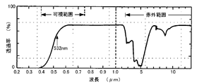
- FIG. 1 is a graph showing light transmittance for type Ib diamond.
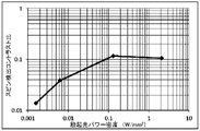
- FIG. 2 is a graph showing the relationship between the spin detection contrast ratio and the power density of excitation light.
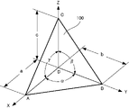
- FIG. 3 is a perspective view showing a diamond magneto-optical sensor according to an embodiment of the present disclosure;
- FIG. 4 is a trihedral view showing the arrangement of the diamond magneto-optical sensor and the optical fiber shown in FIG.
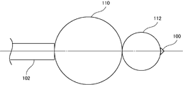
- FIG. 5 is a side view showing a configuration in which a condensing element is arranged between the diamond magneto-optical sensor and the optical fiber.
- FIG. 6 is a schematic diagram showing the optical path of the NV center excitation light incident on the diamond magneto-optical sensor.
- FIG. 7 is a schematic diagram showing the optical path of fluorescence emitted from the NV center of the diamond magneto-optical sensor.
- FIG. 8 is a schematic diagram showing the optical path of fluorescence emitted from diamond without considering the refractive index.
- FIG. 9 is a schematic diagram showing the optical path of fluorescence emitted from diamond in consideration of the refractive index.
- FIG. 10 is a schematic diagram showing the optical path of fluorescence emitted from diamond when a reflecting mirror is provided.
- FIG. 11 is a schematic diagram showing the optical path of fluorescence emitted from a corner cube-shaped diamond.
- FIG. 12 is a cross-sectional view showing the configuration of a diamond magneto-optical sensor according to the first modified example.
- FIG. 12 is a cross-sectional view showing the configuration of a diamond magneto-optical sensor according to the first modified example.
- FIG. 13 is a two-sided view showing the configuration of a diamond magneto-optical sensor according to the second modification.
- FIG. 14 is a perspective view showing the configuration of a diamond magneto-optical sensor according to a second modified example different from that of FIG.
- FIG. 15 is a side view showing the configuration of a diamond magneto-optical sensor according to the third modification.
- FIG. 16 is a perspective view showing the configuration of a diamond magneto-optical sensor according to a fourth modification.
- FIG. 17 is a perspective view showing the configuration of a diamond magneto-optical sensor according to the fifth modification.
- FIG. 18 is a trihedral view showing the arrangement of the diamond magneto-optical sensor and the optical fiber shown in FIG. FIG.
- FIG. 19 is a cross-sectional view showing a diamond magneto-optical sensor having a different tip shape from the diamond magneto-optical sensor shown in FIG.
- FIG. 20 is a perspective view showing the configuration of a diamond magneto-optical sensor according to the sixth modification.
- FIG. 21 is a cross-sectional view showing a diamond magneto-optical sensor having a different tip shape from the diamond magneto-optical sensor shown in FIG.
- FIG. 22 is a perspective view showing the configuration of a diamond magneto-optical sensor according to the seventh modification.
- FIG. 23 is a cross-sectional view showing a diamond magneto-optical sensor having a different tip shape from the diamond magneto-optical sensor shown in FIG.
- FIG. 20 is a perspective view showing the configuration of a diamond magneto-optical sensor according to the sixth modification.
- FIG. 21 is a cross-sectional view showing a diamond magneto-optical sensor having a different tip shape from the diamond magneto-optical sensor shown in FIG.
- FIG. 24 is a perspective view showing the configuration of a diamond magneto-optical sensor according to an eighth modification.
- FIG. 25 is a cross-sectional view showing a diamond magneto-optical sensor having a different tip shape from the diamond magneto-optical sensor shown in FIG.
- FIG. 26 is a schematic diagram showing an example of a configuration for spatial transmission of excitation light and fluorescence.
- FIG. 27 is a schematic diagram showing the configuration of Example 1.
- FIG. 28 is a perspective view showing the configuration of the microwave irradiation unit shown in FIG. 27.
- FIG. FIG. 29 is a graph showing experimental results.
- FIG. 30 is a graph showing comparison results.
- FIG. 31 is a schematic diagram showing the configuration of the second embodiment.
- An optical system that transmits the excitation light from the light source and irradiates the NV center irradiates the excitation light to initialize the spin state of the NV center and read the subsequent change.
- the optical system that collects fluorescence from the NV center and transmits it to the photodetector collects fluorescence that changes according to the spin state of the NV center.
- the efficiency of concentrating the fluorescence emitted from the NV center of diamond, the efficiency of absorption of the excitation light that excites the NV center, and the irradiation power density of the excitation light can be improved.
- Each subject will be specifically described below.
- the fluorescence collection rate from the NV center is at most several percent. Remains at a low degree of efficiency.
- the following formula 7 is known as a theoretical formula for the sensitivity ⁇ B (that is, the resolution of the detected magnetic field B) of the diamond magneto-optical sensor.
- Equation 7 ⁇ is the gyromagnetic ratio (that is, a constant), which is close to the electron gyromagnetic ratio (1.76 ⁇ 10 11 rad/s/T).
- ⁇ is the fluorescence detection efficiency, that is, the light collection efficiency, which remains at several percent as described above.
- C is the spin-detection contrast ratio (ie, red-light intensity reduction rate), which will be described later.
- N is the number of negatively charged NV centers present in the area where the excitation light is applied and the fluorescence is collected.
- T2 is the transverse relaxation time of the electron spin.
- excitation light absorption efficiency In order to initialize the spin state of the NV center and read the subsequent change, excitation light with a wavelength of 532 nm is irradiated.
- a green light semiconductor laser or a YAG double wave solid-state laser As the excitation light source, a green light semiconductor laser or a YAG double wave solid-state laser is easy to use. Diamonds are classified according to the presence or absence of impurities and the type of impurities. Of these, type Ib, which contains nitrogen atoms as impurities (that is, has an NV center), appears yellow and has low transmittance among diamond types.
- the light transmittance for type Ib diamond is shown in FIG. The vertical axis represents transmittance (%) and the horizontal axis represents wavelength ( ⁇ m). In FIG.
- the scale of the horizontal axis differs across the wavelength of 1.0 ⁇ m.
- type Ib diamond transmits green light with a wavelength of 532 nm (that is, 0.532 ⁇ m) to some extent, so the absorption length required for the diamond to absorb light exceeds several millimeters. If the diamond substrate has a short optical path length (for example, a thin thickness), most of the excitation light is transmitted through the substrate, resulting in poor absorption efficiency of the excitation light.
- the relationship between the spin detection contrast ratio (that is, the reduction rate of the red light luminance) and the power density of the excitation light was evaluated experimentally for NV centers formed in a type Ib diamond substrate. The results are shown in FIG. In FIG. 2, the vertical axis represents the spin detection contrast ratio, and the horizontal axis represents the power density of the excitation light. As can be seen from FIG. 2, in order to obtain high sensitivity as a magneto-optical sensor, it is necessary to irradiate the excitation light with a power density of 20 mW/ mm2 or more in order to increase the spin detection contrast ratio to 0.06 or more. I found out.
- the relationship between the response speed (specifically, the time constant) to the frequency change of the microwave and the power density of the excitation light was evaluated by experiments. As a result, in order to obtain a high response speed as a magneto-optical sensor, it was found that it is necessary to increase the power density of the irradiating excitation light.
- an object of the present disclosure is to provide a diamond magneto-optical sensor with high fluorescence collection efficiency and high excitation light absorption efficiency and power density.
- a diamond magneto-optical sensor includes a diamond having a color center with electron spins, and a reflective surface that reflects excitation light that is propagated through an optical system and enters the diamond. and the reflective surface reflects the radiation emitted from the color center excited by the excitation light and converges it in the direction of the optical system.
- the fluorescence light collection efficiency, the excitation light absorption efficiency, and the power density can be improved. Therefore, the responsiveness and sensitivity of the diamond magneto-optical sensor can be improved.
- the excitation light is incident on the diamond from the output of the optical fiber, and the reflective surface can focus the emitted light to the output of the optical fiber.
- the fluorescence collection efficiency, the excitation light absorption efficiency, and the power density can be further improved. Therefore, the responsiveness and sensitivity of the diamond magneto-optical sensor can be further improved.
- a diamond magneto-optical sensor includes a diamond having a color center with electron spins, a minute portion that allows excitation light propagated through an optical system to enter the diamond, a reflective surface that reflects the emitted light emitted from the color center excited by the excitation light incident from the minute portion and converges the light in the direction of the light receiving optical system that guides it to the light receiving element; Radiated light emitted from the same position in different directions is guided to the light-receiving optical system through a plurality of optical paths.
- the fluorescence light collection efficiency, the excitation light absorption efficiency, and the power density can be improved. Therefore, the responsiveness and sensitivity of the diamond magneto-optical sensor can be improved.
- the excitation light may be incident on the diamond from the output portion of the optical fiber via a minute portion, and the emitted light may be focused on the output portion of the optical fiber via the reflecting surface.
- the fluorescence collection efficiency, the excitation light absorption efficiency, and the power density can be further improved. Therefore, the responsiveness and sensitivity of the diamond magneto-optical sensor can be further improved.
- the diamond magneto-optical sensor may further include a member that encloses diamond and transmits excitation light and radiation light, and the member may be formed with a reflecting surface.
- the reflective surface may be formed of diamond.
- the reflective surface may be formed on a member containing diamond.
- a member containing diamond As a result, only the reflective surface is processed on a member that is easier to process than diamond, and the excitation light can be easily focused on the diamond.
- a material having a refractive index closer to that of diamond as a member it is possible to maintain a large refractive index difference with the atmosphere, facilitate the incidence of excitation light on the diamond, and reduce the critical angle on the reflective surface.
- a compact sensor with high reflection efficiency can be formed.
- the reflective surface may include a curved surface or a plurality of planes for focusing.
- the focal point may be a point where two or more different optical paths converge at a position closer than the distance between the two optical paths incident on the diamond, and does not have to be a so-called strict optical focal point.
- the diamond may have a flat surface and a spherical crown, and the reflective surface may be formed by the spherical crown. This makes it easier to design the shape of a diamond with high fluorescence collection efficiency.
- the diamond may have two crowns, and the reflecting surface may be formed by the first of the two crowns. This makes it easier to design the shape of a diamond with high fluorescence collection efficiency.
- the diamond may be formed into a polyhedron, and the reflective surface may be formed of multiple faces of the polyhedron. This facilitates the production of diamond with high fluorescence collection efficiency.
- the reflective surface may have a flat surface, and the angle formed by the surface perpendicular to the incident axis of the excitation light and the flat surface on the incident side of the excitation light may be 20° or more and 70° or less. . This makes it possible to realize a diamond with a high efficiency of condensing fluorescence.
- the angle formed by the vertical plane and the plane may be 30° or more and 50° or less. This makes it possible to realize a diamond with a higher fluorescence collection efficiency.
- the diamond may have corner cubes. This makes it possible to realize a diamond with a higher efficiency of condensing fluorescence.
- the member containing the diamond may have a corner cube. This makes it possible to realize a diamond with a higher efficiency of condensing fluorescence.
- the optical system includes an optical fiber, and the size of the diamond may be 1/3 or more and 3 or less times the core diameter of the optical fiber.
- the diamond can be efficiently irradiated with the excitation light transmitted through the optical fiber, and the fluorescence emitted from the diamond can be efficiently injected into the optical fiber.
- the optical system includes an optical fiber, and the diamond may be larger than or equal to the size that inscribes a circle whose diameter is the core diameter of the optical fiber, and smaller than or equal to the size that circumscribes the circle.
- the diamond can be efficiently irradiated with the excitation light transmitted through the optical fiber, and the fluorescence emitted from the diamond can be efficiently injected into the optical fiber.
- the optical system includes an optical fiber and a lens, and the excitation light propagated through the optical fiber may be output from the lens and incident on the diamond magneto-optical sensor, and the reflective surface may emit light from the color center.
- the emitted light may be focused onto a lens, the magnification of the lens may be the reciprocal of the numerical aperture of the optical fiber, and the size of the diamond may be the product of the core diameter of the optical fiber and the numerical aperture. may be in the range of 80% or more and 120% or less.
- a diamond magneto-optical sensor 100 is made of diamond including NV centers.
- the diamond magneto-optical sensor 100 is formed in a tetrahedron.
- the four points A, B, C and D represent the vertices of a tetrahedron.
- the X, Y and Z axes are indicated along sides AD, BD and CD respectively.
- Lengths a, b and c represent the lengths of sides AD, BD and CD, respectively.
- Angle ⁇ represents the angle formed by side AD and side BD.
- the angle ⁇ represents the angle formed by the side BD and the side CD.
- the angle ⁇ represents the angle formed by the side CD and the side AD.
- the arrangement of the crystal orientation of the diamond magneto-optical sensor 100 is arbitrary and is not necessarily defined by the X, Y and Z axes.
- excitation light is incident perpendicularly to the surface ABC.
- the NV center inside the diamond magneto-optical sensor 100 is irradiated with excitation light, and fluorescence is emitted.
- Three surfaces (that is, surface ABD, surface BCD, and surface ACD) other than surface ABC (that is, incident surface) of diamond magneto-optical sensor 100 are polished to flat surfaces and mirrors (for example, metal plating, metal deposition, etc.) ) function as a reflective surface.
- the omnidirectionally emitted fluorescent light is internally reflected by surfaces ABD, BCD and ACD of diamond magneto-optical sensor 100 and output from surface ABC so that it can be detected by a detector.
- the angles ⁇ , ⁇ , and ⁇ of the diamond magneto-optical sensor 100 are arbitrary.
- the angles ⁇ , ⁇ and ⁇ are preferably all 90°.
- the shape of the diamond magneto-optical sensor 100 in that case is called a corner cube.
- the sides a, b and c of the diamond magneto-optical sensor 100 preferably satisfy 0.5b ⁇ a ⁇ 1.5b and 0.5c ⁇ a ⁇ 1.5c.
- the diamond magneto-optical sensor 100 when used to measure a magnetic field, the diamond magneto-optical sensor 100 is arranged such that the surface ABC (see FIG. 3) is the end of the optical fiber 102 (that is, the output portion of the excitation light). ) are arranged to face each other. Points A, B, C and D, which are vertices of the diamond magneto-optical sensor 100 shown in FIG. 3, are shown in the lower right of FIG.
- the optical fiber 102 may be placed close to (including in contact with) the diamond magneto-optical sensor 100 .
- the optical fiber 102 is preferably arranged such that its optical axis is perpendicular to the plane ABC (that is, the plane of incidence) of the diamond magneto-optical sensor 100 .
- Light for example, a wavelength of about 532 nm
- a light source for example, a laser diode
- Fluorescence emitted from the NV center 104 is internally reflected by the reflective surfaces of the diamond magneto-optical sensor 100 (that is, the surfaces ABD, BCD, and ACD) as described above, and is output from the surface ABC to the optical fiber 102. is transmitted to the detector by
- the angle ⁇ (degrees) formed between the reflecting surface 106 of the diamond magneto-optical sensor 100 (that is, the surface ABD) and the vertical surface 108 perpendicular to the optical axis of the optical fiber 102 is preferably 20 ⁇ 70 (45 ⁇ 25 ⁇ 45+25) because the critical angle for total reflection of a substance with a refractive index of 2.4 is 24.6 degrees.
- the light incident on each reflective surface inside the diamond magneto-optical sensor 100 Light can be reflected forward of the diamond magneto-optical sensor 100 and toward the central axis of the optical fiber 102 . Therefore, it is possible to increase the proportion of the excitation light that is used to excite the NV centers and increase the proportion of emitted fluorescence that enters the optical fiber 102 . More preferably, 24.6 ⁇ 65.4 (45 ⁇ 20.4 ⁇ 45+20.4). More preferably, 38 ⁇ 52 (45 ⁇ (20.4/3) ⁇ 45+(20.4/3)).
- the size of the diamond magneto-optical sensor 100 is preferably 1/3 or more and 3 or less times the core diameter (that is, core diameter) of the optical fiber 102 .
- the size of the diamond magneto-optical sensor 100 means, for example, the size of the circumscribed circle of the surface facing the optical fiber 102 (that is, the incident surface of the excitation light).
- the diamond magneto-optical sensor 100 preferably has a size larger than or equal to that inscribed in a circle whose diameter is the core diameter of the optical fiber 102 and smaller than or equal to a size that circumscribes the circle.
- the excitation light transmitted by the optical fiber 102 can be efficiently incident on the diamond magneto-optical sensor 100 , and the fluorescence emitted from the diamond magneto-optical sensor 100 can be efficiently incident on the core of the optical fiber 102 .
- a condensing element may be arranged between the diamond magneto-optical sensor 100 and the optical fiber 102 .
- focusing elements 110 and 112 are positioned between diamond magneto-optical sensor 100 and optical fiber 102.
- the excitation light transmitted by the optical fiber 102 and output from the end of the optical fiber 102 is condensed by the condensing elements 110 and 112 and irradiated onto the diamond magneto-optical sensor 100 .
- Fluorescence emitted from the NV center of the diamond magneto-optical sensor 100 is condensed by condensing elements 112 and 110 , enters the end of the core of the optical fiber 102 , and is transmitted by the optical fiber 102 .
- the magnification of the lens formed by the condensing elements 110 and 112 is preferably the reciprocal of the numerical aperture NA of the optical fiber 102 (that is, 1/NA).
- the size of the diamond magneto-optical sensor 100 is preferably in the range of 80% to 120% of the product of the core diameter ⁇ of the optical fiber 102 and the numerical aperture NA (that is, ⁇ NA).
- the present invention is not limited to this.
- a light guide in which a plurality of optical fiber cores are bundled may be used instead of the optical fiber 102 .
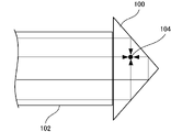
- FIG. 6 shows the optical path inside the diamond magneto-optical sensor 100 of excitation light.
- excitation light (see arrows) transmitted from optical fiber 102 enters diamond magneto-optical sensor 100 and passes through a plurality of reflecting surfaces (ie surface ABD, surface BCD and surface ACD in FIG. 1). , the light is reflected inside the diamond magneto-optical sensor 100 and irradiated to the NV center 104 . That is, the NV center 104 receives pumping light from all directions including not only the pumping light from the front (that is, the optical fiber 102 side) but also the pumping light from the rear, up, down, left and right.
- the irradiation power density of the excitation light incident on the NV center If the absorption is small along the optical path to reach a specific NV center, the irradiation power density of the excitation light can be increased up to 6 times compared to the case of only the excitation light from the front. Thereby, the sensitivity of the diamond magneto-optical sensor can be improved.
- the optical path of the excitation light that is reflected by a plurality of reflective surfaces and enters the NV center 104 is longer than the optical path that directly enters the NV center 104 without being reflected (for example, about twice as long).
- the optical path of the excitation light in the diamond magneto-optical sensor 100 can be made close to the absorption length of diamond, and the absorption efficiency of the excitation light (that is, the quantum efficiency of absorption) can be increased. That is, since the number of NV centers to be excited increases, the emitted fluorescence intensity increases. Thereby, the sensitivity of the diamond magneto-optical sensor can be improved.
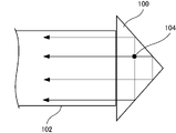
- FIG. 7 shows the optical path of fluorescence emitted from the NV center of the diamond magneto-optical sensor 100.
- FIG. Referring to FIG. 7, inside diamond magneto-optical sensor 100, NV center 104 irradiated with excitation light emits fluorescence (see arrows) in all directions. Among them, the fluorescent light emitted forward (that is, toward the optical fiber 102 side) directly enters the end portion of the optical fiber 102 (that is, the excitation light output portion). On the other hand, the fluorescent light emitted backward, up, down, left, and right is reflected inside the diamond magneto-optical sensor 100 by a plurality of reflecting surfaces (that is, the surfaces ABD, BCD, and ACD in FIG. 1).
- the light is output from the sensor 100 and enters the end of the optical fiber 102 (that is, the excitation light output portion). That is, the fluorescence emitted in all directions can be collected forward, and the fluorescence collection efficiency can be increased. Therefore, the sensitivity of the diamond magneto-optical sensor can be improved.
- FIG. 8 shows the optical path of fluorescence emitted from inside a rectangular (for example, cubic) diamond.
- diamond has a refractive index of 1 and is not considered.
- FIG. 9 shows the optical path of fluorescence emitted from inside the diamond for a diamond of the same shape as in FIG. 8, given the diamond's refractive index n (ie about 2.5).
- the angle .theta. (degrees) of the emitted light with respect to the central axis is in the range of 0.ltoreq..theta..ltoreq.17 (that is, the shaded area) is output from the observation plane (left side plane).
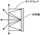
- FIG. 10 shows the optical path of the fluorescence emitted from inside the diamond, considering the refractive index n of the diamond in the same way as in FIG.
- the size of the diamond in the direction perpendicular to the viewing plane is set to 1/2 of that in FIG.
- the angle .theta. (degrees) of the emitted light with respect to the central axis is in the range of 0.ltoreq..theta..ltoreq.17.
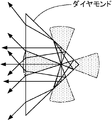
- FIG. 11 shows the optical path of fluorescence emitted from inside a corner-cube diamond, considering the refractive index n of diamond.
- the angle .theta. (degrees) of the emitted light with respect to the central axis is in the range of 0.ltoreq..theta..ltoreq.17.
- the light emitted backward and laterally in the same angular range that is, the shaded area
- the light emitted backward and laterally in the same angular range that is, the shaded area
- the diamond magneto-optical sensor 100 can improve fluorescence collection efficiency, excitation light absorption efficiency, and power density. Therefore, a diamond magneto-optical sensor with improved responsiveness and sensitivity can be realized.
- a diamond magneto-optical sensor is made of diamond has been described above, it is not limited to this. A member other than diamond may be included. A diamond magneto-optical sensor according to the first modification includes members other than diamond.
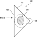
- diamond magneto-optical sensor 120 has diamond 122 including NV centers and glass 124 enclosing diamond 122 .
- the shape of the glass 124 is similar to that of the diamond magneto-optical sensor 100 shown in FIG. 3 (for example, a corner cube).
- the conditions for the dimensions of the sides of the glass 124 (i.e. a, b and c shown in FIG. 3) and the angles (i.e. ⁇ , ⁇ and ⁇ shown in FIG. 3) are also given for the diamond magneto-optical sensor 100. should be the same as As described above, in FIG.
- the excitation light incident on the incident surface 126 is reflected by the reflecting surface 128 inside the diamond magneto-optical sensor 120, and is concentrated inside the dashed-dotted line (hereinafter referred to as the excitation light increase area). do. Therefore, the size of the diamond 122 may be such that at least a portion of the diamond 122 exists inside the excitation light increasing area, and the shape of the diamond 122 is arbitrary.
- the glass 124 By forming the glass 124 around the diamond, the amount of diamond can be reduced and the cost of the diamond magneto-optical sensor can be reduced. Further, since the glass may be cut into the shape of a corner cube, the diamond magneto-optical sensor can be manufactured more easily than when diamond is cut.
- the member containing the diamond 122 is not limited to glass.
- a resin may be used as long as it has a high transmittance for green light (that is, wavelengths of about 490 to 560 nm) and red light (that is, wavelengths of about 630 to 800 nm). Since the refractive index of the glass 124 is smaller than that of diamond, it is preferable to process the surface of the reflecting surface 128 flat and provide a mirror (for example, metal plating, metal vapor deposition, etc.).
- the diamond magneto-optical sensor according to the second modification has a curved reflecting surface.
- a diamond magneto-optical sensor 130 includes an NV center and has a plane incident surface 132 and a curved reflecting surface 134 .
- the excitation light is incident on the incident surface 132 .
- the reflective surface 134 is a curved surface connecting a focal point 136 such as a paraboloid or an ellipsoid.
- the reflecting surface 134 may have a concave shape when viewed from the incident surface 132 side. If the reflecting surface 134 has a concave shape, the excitation light incident on the diamond magneto-optical sensor 130 from the incident surface 132 is reflected forward (that is, toward the incident surface 132) by the reflecting surface 134 inside the diamond magneto-optical sensor 130. .
- the optical path of the excitation light is lengthened, and the absorption efficiency of the excitation light at the NV center can be increased. Fluorescence emitted from the NV center is reflected forward (that is, toward the incident surface 132 side) by the reflecting surface 134 inside the diamond magneto-optical sensor 130 , condensed, and output from the incident surface 132 . Therefore, fluorescence collection efficiency can be increased.
- a diamond magneto-optical sensor 140 includes an NV center and has a plane incident surface 142 and a curved reflecting surface 144 .
- the diamond magneto-optical sensor 140 is a sphere that does not include the center O and is obtained by cutting a sphere with a radius r along a plane that does not pass through the center O of the sphere.
- Reflective surface 144 is a portion of a truncated spherical surface (ie, crown). The excitation light enters the diamond magneto-optical sensor 140 from the incident surface 142 .
- the excitation light incident on the diamond magneto-optical sensor 140 is reflected forward (that is, toward the incident surface 142 ) by the reflecting surface 144 inside the diamond magneto-optical sensor 140 . Therefore, the optical path of the excitation light is lengthened, and the absorption efficiency of the excitation light at the NV center can be increased. Fluorescence emitted from the NV center is reflected forward (that is, to the incident surface 142 side) by the reflecting surface 144 inside the diamond magneto-optical sensor 140 , condensed, and output from the incident surface 142 . Therefore, fluorescence collection efficiency can be increased.
- the lengths d and e shown in FIG. 14 it is preferred that r>d>3r/4 and 3r/2>e>r/2.
- the length d is the diameter of the entrance surface 142 and the length e is the height of the spheroid (ie, the maximum vertical distance from the entrance surface 142 to the crown).
- the diamond magneto-optical sensor according to the second modification may also be formed so as to include diamond including the NV center and glass enclosing it.
- the diamond encapsulating glass is formed into the shape shown in FIG. 13 or 14 .
- the diamond magneto-optical sensor according to the third modification has a curved incident surface.
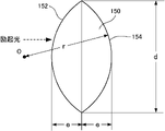
- a diamond magneto-optical sensor 150 includes an NV center and has a curved incident surface 152 and a curved reflecting surface 154 . Both the incident surface 152 and the reflecting surface 154 are spherical crowns, and the diamond magneto-optical sensor 150 has a shape in which two spherical segments are joined with a plane.
- the excitation light enters the diamond magneto-optical sensor 150 from the incident surface 152 .
- the excitation light incident on the diamond magneto-optical sensor 150 is reflected forward (that is, toward the incident surface 152 side) by the reflecting surface 154 inside the diamond magneto-optical sensor 150 .
- the optical path of the excitation light is lengthened, and the absorption efficiency of the excitation light at the NV center can be increased. Fluorescence emitted from the NV center is reflected forward (that is, toward the incident surface 152 side) by the reflecting surface 154 inside the diamond magneto-optical sensor 150 , condensed, and output from the incident surface 152 . Therefore, fluorescence collection efficiency can be increased.
- the reflective surface 154 is formed by two truncated spheres of radius r as shown in FIG. 14, r>d>3r/4 for lengths d and e shown in FIG. , and preferably 3r/2>e>r/2. If the diamond magneto-optical sensor 150 has such a shape, when the excitation light is incident on the incident surface 152 in parallel with the axis perpendicular to the joint surface of the incident surface 152 and the reflecting surface 154, the excitation light is detected as a diamond magneto-optical sensor. Light can be collected inside the sensor 150 .
- the diamond magneto-optical sensor according to the third modification may also be formed so as to include diamond including the NV center and glass enclosing it.
- the diamond encapsulating glass is formed into the shape shown in FIG.
- a diamond magneto-optical sensor according to the fourth modification is a polyhedron having five or more faces.
- a diamond magneto-optical sensor 160 includes an NV center and is formed into a triangular prism (that is, a pentahedron). etc.).
- the excitation light enters the diamond magneto-optical sensor 160 from the incident surface 162 .
- the excitation light incident on the diamond magneto-optical sensor 160 is reflected forward (that is, toward the incident surface 162 ) by a plurality of reflecting surfaces such as the reflecting surface 164 inside the diamond magneto-optical sensor 160 . Therefore, the optical path of the excitation light is lengthened, and the absorption efficiency of the excitation light at the NV center can be increased.
- Fluorescence emitted from the NV center is reflected forward (i.e., toward the incident surface 162 side) by a plurality of reflecting surfaces such as the reflecting surface 164 inside the diamond magneto-optical sensor 160 and condensed, and is output from the incident surface 162. . Therefore, fluorescence collection efficiency can be increased.
- the angle .delta. shown in FIG. 16 is preferably 90 degrees.
- the incident surface 162 is preferably square, that is, two orthogonal sides having the same length h and i. Moreover, it is preferable that the lengths f, g, h and i satisfy the following relationship. g ⁇ (1/1.4 ⁇ 0.5) ⁇ f ⁇ g ⁇ (1/1.4+0.5) h ⁇ (1/1.4 ⁇ 0.5) ⁇ f ⁇ h ⁇ (1/1.4+0.5) i ⁇ (1/1.4 ⁇ 0.5) ⁇ f ⁇ i ⁇ (1/1.4+0.5)
- the diamond magneto-optical sensor may be a polyhedron of hexahedron or more.
- the curved reflection surface shown in FIGS. 13 and 14 may be a polyhedron approximated by a plurality of planes.
- the diamond magneto-optical sensor according to the fourth modification may also be formed so as to include diamond including the NV center and glass enclosing it.
- the diamond-containing glass is formed into a polyhedron of pentahedrons or more (for example, the triangular prism shown in FIG. 16).
- a diamond magneto-optical sensor 400 is made of diamond including an NV center, and has a substantially triangular pyramid (specifically, a truncated triangular pyramid).
- the diamond magneto-optical sensor 400 can be formed, for example, by cutting a portion including the vertex D from the diamond magneto-optical sensor 100 shown in FIG. 3 along a predetermined plane.
- excitation light is applied to diamond magneto-optical sensor 400 by irradiating minute portion 402 using optical fiber 408 .
- the excitation light is emitted from the optical fiber 408 perpendicularly to the plane of the minute portion 402 . Therefore, the excitation light emitted from the optical fiber 408 enters the diamond magneto-optical sensor 400 through the minute portion 402 .
- Fluorescence is emitted from the NV center 104 by excitation light that has entered the diamond magneto-optical sensor 400 .
- the emitted fluorescent light is reflected by reflecting surface 404 , output from output surface 410 , and enters optical fiber 102 . Fluorescence incident on the optical fiber 102 is transmitted by the optical fiber 102 to a detector.
- the minute portion 402 is a portion having a smaller area than the reflecting surface 404, as long as it satisfies the optical incident condition to the diamond magneto-optical sensor 400, and does not have to be flat as described later.
- the minute portion 402 preferably has a size of sub- ⁇ m or more, which is enough for laser light (that is, excitation light) to enter.
- the position of the minute portion 402 is such that the radiated light (that is, fluorescence) from the NV center due to the excitation light incident on the diamond magneto-optical sensor 400 is reflected by the reflecting surface and concentrated toward the optical system that receives the radiated light. It is preferable to be in a position where it can be illuminated.
- condensing means a function of concentrating light with a wide angle so that it is directed toward a target direction.
- diamond magneto-optical sensor 420 has minute portion 422 and reflecting surface 424 .
- the reflective surface 424 is substantially triangular pyramidal like the reflective surface 404 .
- the shape of the minute portion 422 is not flat but a smooth curved surface. Therefore, as indicated by the solid line arrow, the excitation light incident on the minute portion 422 is mainly incident on the inside of the diamond magneto-optical sensor 420 . As indicated by the dashed arrow, the light incident on the portion other than the minute portion 422 (that is, the reflecting surface 424) is mainly reflected and cannot enter the diamond magneto-optical sensor 420.
- the shape of the minute portion may not be flat, and may be any shape that allows the excitation light to enter the diamond magneto-optical sensor 420 . Fluorescence emitted from the NV center 104 by the excitation light incident on the diamond magneto-optical sensor 420 is reflected by the reflecting surface 424 and output from the side opposite to the incident side of the excitation light.
- a diamond magneto-optical sensor 430 according to the sixth modification has a minute portion 432 and a reflecting surface 434, and the minute portion 432 and the reflecting surface 434 are formed as a smooth curved surface as a whole. there is Therefore, as indicated by the solid line arrow, the excitation light incident on the minute portion 432 is mainly incident on the inside of the diamond magneto-optical sensor 430 .
- the light incident on the portion other than the minute portion 432 (that is, the reflecting surface 434) is mainly reflected and cannot enter the diamond magneto-optical sensor 430.
- FIG. Fluorescence emitted from the NV center 104 by the excitation light incident on the diamond magneto-optical sensor 430 is reflected by the reflecting surface 434 and output from the side opposite to the incident side of the excitation light.
- a diamond magneto-optical sensor 440 has a minute portion 442 and a reflecting surface 444, the reflecting surface 444 being a smooth curved surface and the minute portion 442 being a flat surface.
- the optical paths of excitation light and fluorescence are the same as in FIG.
- a diamond magneto-optical sensor 450 in the fifth and sixth modifications, the diamond magnetic sensor is entirely made of diamond, but the present invention is not limited to this.
- a diamond magneto-optical sensor 450 according to the seventh modification includes glass 452 having minute portions 454 and reflecting surfaces 456 and diamond 122 .
- a diamond magneto-optical sensor 450 includes diamond 122 including an NV center inside glass 452 as in FIG.
- the shape of the glass 452 is the same shape as the diamond magneto-optical sensor 400 shown in FIGS. 17 and 18 (that is, a truncated triangular pyramid). Therefore, as indicated by the solid line arrow, the excitation light incident on the minute portion 454 is mainly incident on the inside of the glass 452 and is incident on the diamond 122 .
- the light incident on the portion other than the minute portion 454 ie, the reflecting surface 456
- the light incident on the portion other than the minute portion 454 is mainly reflected and cannot enter the interior of the glass 452 and is not incident on the diamond 122.
- FIG. Fluorescence emitted from the NV center of the diamond 122 by the excitation light incident on the glass 452 is reflected by the reflecting surface 456 and output from the side opposite to the excitation light incident side.
- diamond magneto-optical sensor 460 includes glass 462 having minute portion 464 and reflective surface 466 and diamond 122 .
- a diamond 122 containing an NV center is encapsulated inside glass 462 .
- the shape of the glass 462 is similar to that of the diamond magneto-optical sensor 420 shown in FIG. That is, the minute portion 464 is not flat but a smooth curved surface.
- the optical paths of excitation light and fluorescence are the same as in FIG.
- the diamond 122 may have any size as long as at least a portion of it exists inside the excitation light increasing area (that is, within the dashed line in FIG. 12), and the shape of the diamond 122 is arbitrary.
- the amount of diamond can be reduced, and the cost of the diamond magneto-optical sensor can be reduced.
- the diamond magneto-optical sensor can be manufactured more easily than when diamond is cut.
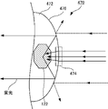
- a diamond magneto-optical sensor 470 includes glass 472 having minute portions 474 and reflecting surfaces 476 and diamond 122 .
- Glass 472 encapsulates diamond 122 containing NV centers.
- the shape of the glass 472 is similar to that of the diamond magneto-optical sensor 430 shown in FIG. That is, the minute portion 474 of the glass 472 and the reflecting surface 476 are formed as a smooth curved surface as a whole. Therefore, as indicated by solid-line arrows, the excitation light incident on the minute portion 474 is mainly incident on the inside of the glass 472 and is incident on the diamond 122 .
- light incident on portions other than the minute portion 474 (that is, the reflective surface 476 ) is mainly reflected and cannot enter the interior of the glass 472 and is not incident on the diamond 122 .
- Fluorescence emitted from the NV center of the diamond 122 by the excitation light incident on the glass 472 is reflected by the reflective surface 476 and output from the side opposite to the incident side of the excitation light.
- diamond magneto-optical sensor 480 includes glass 482 having minute portion 484 and reflective surface 486 and diamond 122 .
- Glass 482 encapsulates diamond 122 containing NV centers.
- the shape of the glass 482 is similar to that of the diamond magneto-optical sensor 440 shown in FIG.
- the minute portion 484 is a smooth curved surface and the glass 482 is a flat surface.
- the optical paths of excitation light and fluorescence are the same as in FIG.
- the glass described above is preferably quartz glass from the viewpoint of light transmittance, ease of processing, and ease of handling. More preferably, the glass is a material that can transmit 90% or more of excitation light and fluorescent light and has a high refractive index. This is because the critical angle for total reflection becomes large on a glass reflecting surface (for example, the reflecting surface 456 in FIG. 22), and the amount of fluorescent light that can be collected increases. In addition, internal reflection is reduced at the interface between glass and diamond (for example, the interface between glass 452 and diamond 122 in FIG. 22), and light (ie, excitation light) easily penetrates inside the diamond.
- a sensor unit can be configured using the diamond magneto-optical sensor described above. That is, the sensor unit includes, as described above, a diamond magneto-optical sensor including an NV center, an irradiation unit for irradiating the diamond magneto-optical sensor with excitation light, and a detector for detecting the radiated light from the NV center of the diamond magneto-optical sensor. and an optical waveguide for transmitting excitation light and emission light.
- a sensor unit with fast responsiveness and high sensitivity can be realized.
- a diamond magneto-optical sensor having a color center with electron spin may be used.
- a color center having an electron spin is a center that forms a spin triplet state and emits light when excited, and NV centers are typical examples.
- silicon-vacancy centers (ie Si-V centers), germanium-vacancy centers (ie Ge-V centers), and tin-vacancy centers (ie Sn-V centers) also have color with electron spin. Centers are known to exist. Therefore, a diamond magneto-optical sensor may be constructed by using diamond containing these instead of diamond containing NV centers.
- excitation light and fluorescence are transmitted to the diamond magneto-optical sensor by an optical fiber, but it is not limited to this.
- the excitation light and fluorescence may be spatially transmitted.
- excitation light output from a light source 500 can be collimated by a collimating lens 502, reflected by a dichroic mirror 504, condensed by a collimating lens 506, and irradiated onto the diamond magneto-optical sensor 100. .
- Fluorescence emitted from the NV center of the diamond magneto-optical sensor 100 is collimated by the collimating lens 506, passes through the dichroic mirror 504, is collected by the collimating lens 508, and is detected by the photodetector 510.
- Type Ib diamond is used, and electrons are injected into it with an electron beam acceleration energy of 3 MeV and an electron beam dose of 3 ⁇ 10 18 /cm 2 . produced a diamond containing This was cut into a corner cube with a hypotenuse of 1 mm to fabricate a diamond magneto-optical sensor. Also, a diamond magneto-optical sensor was produced as a comparative example by cutting into a cube with one side of 1 mm.
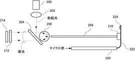
- a diamond magneto-optical sensor having an NV center was irradiated with excitation light using the measuring device having the configuration shown in FIG. 27, and the fluorescence intensity emitted from the NV center was measured.
- the configuration (i.e., irradiation system) for irradiating the diamond magneto-optical sensor 210 with excitation light in the measurement apparatus includes a light source 200, a collimator lens 202, a dichroic mirror 204, a ball lens 206, and an optical fiber. 208.
- a configuration (that is, an observation system) for observing fluorescence emitted from the diamond magneto-optical sensor 210 includes an optical fiber 208 , a ball lens 206 , a dichroic mirror 204 , an LPF (Long Pass Filter) 212 and a photodetector 214 .
- a configuration for irradiating the diamond magneto-optical sensor 210 with microwaves includes a coaxial cable 220 , a microwave irradiation section 222 and a terminating resistor 224 .
- An LD (laser diode) element (specifically, L515A1 manufactured by Thorlabs) was used as the light source 200 for generating excitation light to generate 5 mW green laser light (that is, excitation light).
- the excitation light output from the light source 200 was condensed by the collimator lens 202 and then made incident on the dichroic mirror 204 .
- LA1116-A manufactured by Thorlabs was used for the collimating lens 202, and SO6-RG manufactured by Suruga Seiki Co., Ltd. was used for the dichroic mirror 204.
- the excitation light (that is, green light) incident on the dichroic mirror 204 is reflected by the dichroic mirror 204 .
- the reflected light was condensed by a ball lens 206 , entered into an optical fiber 208 (specifically, a core), transmitted through the optical fiber 208 , and irradiated to a diamond magneto-optical sensor 210 .
- an optical fiber 208 specifically, a core
- For the ball lens 206 MS-08-4.35P1 (diameter 8 mm) manufactured by Opto Sigma was used.
- An optical digital cable with a core diameter of ⁇ 0.9 mm was used as the optical fiber 208 .
- the fluorescence incident on the optical fiber 208 was propagated through the optical fiber 208 , converted into parallel light by the ball lens 206 , and made incident on the dichroic mirror 204 .
- the fluorescence (that is, red light) that has entered the dichroic mirror 204 is transmitted through the dichroic mirror 204 and enters the LPF 212 .
- Fluorescence that passed through LPF 212 was detected by photodetector 214 .
- the LPF 212 passes light of wavelengths equal to or greater than a predetermined wavelength, and cuts (for example, reflects) light of wavelengths smaller than a predetermined wavelength.
- LPF212 For LPF212, LOPF-25C-593 manufactured by Opto Sigma was used. A photodiode (specifically, S6967 manufactured by Hamamatsu Photonics K.K.) was used for the photodetector 214 . Diamond's emission light is red light and passes through the LPF 212 , whereas the excitation light has a shorter wavelength and does not pass through the LPF 212 . This prevents the excitation light emitted from the light source 200 from being detected by the photodetector 214 and becoming noise, thereby reducing the detection sensitivity.
- a photodiode specifically, S6967 manufactured by Hamamatsu Photonics K.K.
- microwave irradiating portion 222 is a coplanar line, and conductors 302 and 304 are formed separately on the surface of electrically insulating flexible substrate 300 .
- Conductors 302 and 304 were formed from copper foil and terminated at region 306 with a 50 ⁇ termination resistor 224 (see FIG. 27).
- a diamond magneto-optical sensor 210 was placed in region 308 .
- the frequency of the microwave irradiated to the diamond magneto-optical sensor 210 is changed in the range of 2.74 GHz to 2.94 GHz, and the diamond magneto-optical sensor 210 is irradiated with excitation light, and the generated fluorescence is observed with a photodetector. 214 output voltage was measured.
- FIG. 29 shows the results of using corner-cube diamond as the diamond magneto-optical sensor 210 .
- FIG. 30 shows the results of a comparative example using a flat diamond as the diamond magneto-optical sensor 210 .
- the vertical axis is the voltage (V) representing fluorescence intensity, and the horizontal axis is the microwave frequency. Black circles are plotted measurement data.
- the fluorescence intensity is about 2440 mV
- the spin detection contrast ratio that is, the rate of decrease in red light intensity, which is the value obtained by dividing the valley size s in the graph by the fluorescence intensity
- the signal strength multiplied by them will be approximately 50 mV.
- the fluorescence intensity was approximately 520 mV, and a contrast ratio of approximately 0.3% was obtained.
- the signal strength multiplied by them is approximately 1.7 mV. Therefore, by using the corner-cube diamond magneto-optical sensor, the fluorescence intensity could be increased by about 5 times, and the contrast ratio could be increased by about 6 times. Therefore, the signal strength could be significantly increased by a factor of about 30.
- a diamond magneto-optical sensor was fabricated in the same manner as in Example 1. That is, using type Ib diamond, electrons are injected with an electron beam acceleration energy of 3 MeV and an electron beam dose of 3 ⁇ 10 18 /cm 2 , and then annealed at 800° C. for about 1 hour to form NV centers. Generated a diamond containing. This was cut into a corner cube with an oblique side of 1 mm, and a minute portion (that is, an incident portion of the excitation light to the diamond) was formed at the vertex portion to prepare a diamond magneto-optical sensor. Also, a diamond magneto-optical sensor was produced as a comparative example by cutting into a cube with one side of 1 mm.
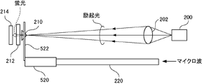
- the vertex (that is, a minute portion) of the diamond magneto-optical sensor having the NV center is irradiated with excitation light (see FIG. 18), and the fluorescence intensity emitted from the NV center is measured.
- the configuration for irradiating diamond magneto-optical sensor 210 with excitation light (that is, irradiation system) of the measuring apparatus includes light source 200 and collimator lens 202 .
- a configuration (that is, an observation system) for observing fluorescence emitted from the diamond magneto-optical sensor 210 includes an LPF 212 and a photodetector 214 .
- a configuration (ie microwave system) for applying microwaves to the diamond magneto-optical sensor 210 includes a coaxial cable 220 , a ⁇ /4 transformer 520 and a ⁇ /4 open stub 522 .
- Example 2 The same light source 200, collimating lens 202, and photodetector 214 as in Example 1 were used. Unlike Example 1, FGL590 manufactured by Thorlabs was used for LPF212.
- the coaxial cable 220 a coaxial cable with a characteristic impedance of 50 ⁇ , which is the same as that of the first embodiment, is used.
- the ⁇ /4 transformer 520 was composed of a microstrip line and its impedance was 20 ⁇ .
- the ⁇ /4 open stub 522 was composed of two parallel lines and its impedance was 300 ⁇ .
- the ⁇ /4 transformer 520 functions as an impedance converter, can accurately convert impedance between the coaxial cable 220 and the ⁇ /4 open stub 522 which is a resonator, and efficiently converts microwaves into diamond magneto-optical sensors. 210 could be irradiated.
- Green light of 5 mW was irradiated as excitation light.
- the spot of excitation light was narrowed down to a diameter of 20 ⁇ m, and the power density was set to 3 W/mm 2 .
- a microwave of 1 W was swept in the frequency range from 2.74 GHz to 2.94 GHz to irradiate the diamond magneto-optical sensor 210 with excitation light, and the generated fluorescence was measured.
- a response speed of 30 .mu.sec was obtained for both the diamond cut into the corner cubes and the diamond of the comparative example.
- the photocurrent in the photodiode of the photodetector 214 which corresponds to the fluorescence intensity, was 10 ⁇ A for the comparative diamond, while 100 ⁇ A was obtained for the corner-cube cut diamond.
Landscapes
- Physics & Mathematics (AREA)
- Condensed Matter Physics & Semiconductors (AREA)
- General Physics & Mathematics (AREA)
- Engineering & Computer Science (AREA)
- Power Engineering (AREA)
- Investigating, Analyzing Materials By Fluorescence Or Luminescence (AREA)
Priority Applications (4)
| Application Number | Priority Date | Filing Date | Title |
|---|---|---|---|
| CN202280025308.4A CN117120863A (zh) | 2021-03-31 | 2022-03-29 | 金刚石光磁传感器 |
| JP2023511368A JPWO2022210695A1 (cg-RX-API-DMAC7.html) | 2021-03-31 | 2022-03-29 | |
| EP22780906.8A EP4318011A4 (en) | 2021-03-31 | 2022-03-29 | MAGNETOOPTICAL DIAMOND SENSOR |
| US18/283,751 US20240175945A1 (en) | 2021-03-31 | 2022-03-29 | Diamond magneto-optical sensor |
Applications Claiming Priority (2)
| Application Number | Priority Date | Filing Date | Title |
|---|---|---|---|
| JP2021-059798 | 2021-03-31 | ||
| JP2021059798 | 2021-03-31 |
Publications (1)
| Publication Number | Publication Date |
|---|---|
| WO2022210695A1 true WO2022210695A1 (ja) | 2022-10-06 |
Family
ID=83459435
Family Applications (1)
| Application Number | Title | Priority Date | Filing Date |
|---|---|---|---|
| PCT/JP2022/015393 Ceased WO2022210695A1 (ja) | 2021-03-31 | 2022-03-29 | ダイヤモンド光磁気センサ |
Country Status (5)
| Country | Link |
|---|---|
| US (1) | US20240175945A1 (cg-RX-API-DMAC7.html) |
| EP (1) | EP4318011A4 (cg-RX-API-DMAC7.html) |
| JP (1) | JPWO2022210695A1 (cg-RX-API-DMAC7.html) |
| CN (1) | CN117120863A (cg-RX-API-DMAC7.html) |
| WO (1) | WO2022210695A1 (cg-RX-API-DMAC7.html) |
Cited By (4)
| Publication number | Priority date | Publication date | Assignee | Title |
|---|---|---|---|---|
| WO2024262524A1 (ja) * | 2023-06-20 | 2024-12-26 | 住友電気工業株式会社 | ダイヤモンドスピンセンサシステム |
| WO2024262525A1 (ja) * | 2023-06-20 | 2024-12-26 | 住友電気工業株式会社 | ダイヤモンドスピンセンサおよびダイヤモンドスピンセンサシステム |
| WO2025182849A1 (ja) * | 2024-02-28 | 2025-09-04 | 住友電気工業株式会社 | ダイヤモンドセンサ |
| WO2025182850A1 (ja) * | 2024-02-28 | 2025-09-04 | 住友電気工業株式会社 | ダイヤモンドスピンセンサおよびその製造方法 |
Families Citing this family (1)
| Publication number | Priority date | Publication date | Assignee | Title |
|---|---|---|---|---|
| CN117930099B (zh) * | 2024-03-21 | 2024-06-07 | 中国科学技术大学 | 光纤集成金刚石探针扫描探测装置及金刚石探针连接方法 |
Citations (14)
| Publication number | Priority date | Publication date | Assignee | Title |
|---|---|---|---|---|
| US20150192532A1 (en) * | 2014-01-08 | 2015-07-09 | Massachusetts Institute Of Technology | Methods and apparatus for optically detecting magnetic resonance |
| US20170023487A1 (en) * | 2015-07-23 | 2017-01-26 | Lockheed Martin Corporation | Light collection from dnv sensors |
| JP2017067650A (ja) * | 2015-09-30 | 2017-04-06 | 国立大学法人北陸先端科学技術大学院大学 | 近接場プローブ構造および走査プローブ顕微鏡 |
| JP2017146158A (ja) * | 2016-02-16 | 2017-08-24 | ルネサスエレクトロニクス株式会社 | 磁気計測装置 |
| DE102018219750A1 (de) * | 2018-11-19 | 2020-05-20 | Robert Bosch Gmbh | Licht-Wellenleiterstruktur für effiziente Lichtanregung und Photonen-Detektion für Farbzentren in Diamant |
| JP2020106352A (ja) * | 2018-12-27 | 2020-07-09 | スミダコーポレーション株式会社 | 励起光照射装置および励起光照射方法 |
| WO2020157497A1 (en) * | 2019-01-30 | 2020-08-06 | The University Of Warwick | Defect centre-based sensor |
| CN111679098A (zh) * | 2020-06-01 | 2020-09-18 | 电子科技大学 | 一种基于金刚石nv色心的磁性液体差分加速度计 |
| CN111678896A (zh) * | 2020-06-01 | 2020-09-18 | 电子科技大学 | 一种金刚石nv色心荧光高效率收集装置 |
| JP2020176994A (ja) * | 2019-04-22 | 2020-10-29 | スミダコーポレーション株式会社 | 励起光照射装置および励起光照射方法 |
| CN111896511A (zh) * | 2020-08-05 | 2020-11-06 | 中国科学技术大学 | 用于固态自旋的高效荧光收集装置及方法 |
| JP2021059798A (ja) | 2019-10-04 | 2021-04-15 | アイトス株式会社 | 送風機付き衣服 |
| KR20210075402A (ko) * | 2019-12-13 | 2021-06-23 | 한국표준과학연구원 | 다이아몬드 질소 공석 자기장 센서 |
| WO2021246064A1 (ja) * | 2020-06-04 | 2021-12-09 | スミダコーポレーション株式会社 | 励起光照射装置および励起光照射方法 |
Family Cites Families (8)
| Publication number | Priority date | Publication date | Assignee | Title |
|---|---|---|---|---|
| JP3555114B2 (ja) * | 1993-03-10 | 2004-08-18 | 住友電気工業株式会社 | ダイヤモンドの平坦化法 |
| JP2006062923A (ja) * | 2004-08-27 | 2006-03-09 | Sumitomo Electric Ind Ltd | ダイヤモンドドーム部品およびその製造方法 |
| US8193808B2 (en) * | 2009-09-11 | 2012-06-05 | Hewlett-Packard Development Company, L.P. | Optically integrated biosensor based on optically detected magnetic resonance |
| GB201107552D0 (en) * | 2011-05-06 | 2011-06-22 | Element Six Ltd | Diamond sensors, detectors, and quantum devices |
| CN105372726A (zh) * | 2015-12-14 | 2016-03-02 | 中山大学 | 一种金刚石微透镜阵列及其制备方法 |
| US10677953B2 (en) * | 2016-05-31 | 2020-06-09 | Lockheed Martin Corporation | Magneto-optical detecting apparatus and methods |
| JP7144730B2 (ja) * | 2018-09-03 | 2022-09-30 | 株式会社デンソー | ダイヤモンドセンサシステム |
| CN113933906B (zh) * | 2021-11-15 | 2024-02-13 | 中国电子科技集团公司第十三研究所 | 金刚石nv色心磁力探测模块及磁力探测系统 |
-
2022
- 2022-03-29 JP JP2023511368A patent/JPWO2022210695A1/ja active Pending
- 2022-03-29 CN CN202280025308.4A patent/CN117120863A/zh active Pending
- 2022-03-29 EP EP22780906.8A patent/EP4318011A4/en active Pending
- 2022-03-29 WO PCT/JP2022/015393 patent/WO2022210695A1/ja not_active Ceased
- 2022-03-29 US US18/283,751 patent/US20240175945A1/en active Pending
Patent Citations (14)
| Publication number | Priority date | Publication date | Assignee | Title |
|---|---|---|---|---|
| US20150192532A1 (en) * | 2014-01-08 | 2015-07-09 | Massachusetts Institute Of Technology | Methods and apparatus for optically detecting magnetic resonance |
| US20170023487A1 (en) * | 2015-07-23 | 2017-01-26 | Lockheed Martin Corporation | Light collection from dnv sensors |
| JP2017067650A (ja) * | 2015-09-30 | 2017-04-06 | 国立大学法人北陸先端科学技術大学院大学 | 近接場プローブ構造および走査プローブ顕微鏡 |
| JP2017146158A (ja) * | 2016-02-16 | 2017-08-24 | ルネサスエレクトロニクス株式会社 | 磁気計測装置 |
| DE102018219750A1 (de) * | 2018-11-19 | 2020-05-20 | Robert Bosch Gmbh | Licht-Wellenleiterstruktur für effiziente Lichtanregung und Photonen-Detektion für Farbzentren in Diamant |
| JP2020106352A (ja) * | 2018-12-27 | 2020-07-09 | スミダコーポレーション株式会社 | 励起光照射装置および励起光照射方法 |
| WO2020157497A1 (en) * | 2019-01-30 | 2020-08-06 | The University Of Warwick | Defect centre-based sensor |
| JP2020176994A (ja) * | 2019-04-22 | 2020-10-29 | スミダコーポレーション株式会社 | 励起光照射装置および励起光照射方法 |
| JP2021059798A (ja) | 2019-10-04 | 2021-04-15 | アイトス株式会社 | 送風機付き衣服 |
| KR20210075402A (ko) * | 2019-12-13 | 2021-06-23 | 한국표준과학연구원 | 다이아몬드 질소 공석 자기장 센서 |
| CN111679098A (zh) * | 2020-06-01 | 2020-09-18 | 电子科技大学 | 一种基于金刚石nv色心的磁性液体差分加速度计 |
| CN111678896A (zh) * | 2020-06-01 | 2020-09-18 | 电子科技大学 | 一种金刚石nv色心荧光高效率收集装置 |
| WO2021246064A1 (ja) * | 2020-06-04 | 2021-12-09 | スミダコーポレーション株式会社 | 励起光照射装置および励起光照射方法 |
| CN111896511A (zh) * | 2020-08-05 | 2020-11-06 | 中国科学技术大学 | 用于固态自旋的高效荧光收集装置及方法 |
Non-Patent Citations (3)
| Title |
|---|
| DUAN DEWEN, KAVATAMANE VINAYA KUMAR, ARUMUGAM SRI RANJINI, RAHANE GANESH, TZENG YAN-KAI, CHANG HUAN-CHENG, SUMIYA HITOSHI, ONODA S: "Enhancing fluorescence excitation and collection from the nitrogen-vacancy center in diamond through a micro-concave mirror", APPLIED PHYSICS LETTERS, vol. 113, no. 4, 23 July 2018 (2018-07-23), pages 1 - 5, XP055974712, ISSN: 0003-6951, DOI: 10.1063/1.5037807 * |
| See also references of EP4318011A4 |
| SHARMA SARVAGYA; HOVDE CHRIS; BECK DOUGLAS H.: "Diamond-based field sensor for nEDM experiment", PROCEEDINGS OF SPIE, vol. 9755, 13 February 2016 (2016-02-13), US , pages 97552U - 97552U-10, XP060070083, ISBN: 978-1-5106-1533-5, DOI: 10.1117/12.2211910 * |
Cited By (4)
| Publication number | Priority date | Publication date | Assignee | Title |
|---|---|---|---|---|
| WO2024262524A1 (ja) * | 2023-06-20 | 2024-12-26 | 住友電気工業株式会社 | ダイヤモンドスピンセンサシステム |
| WO2024262525A1 (ja) * | 2023-06-20 | 2024-12-26 | 住友電気工業株式会社 | ダイヤモンドスピンセンサおよびダイヤモンドスピンセンサシステム |
| WO2025182849A1 (ja) * | 2024-02-28 | 2025-09-04 | 住友電気工業株式会社 | ダイヤモンドセンサ |
| WO2025182850A1 (ja) * | 2024-02-28 | 2025-09-04 | 住友電気工業株式会社 | ダイヤモンドスピンセンサおよびその製造方法 |
Also Published As
| Publication number | Publication date |
|---|---|
| EP4318011A4 (en) | 2024-06-05 |
| JPWO2022210695A1 (cg-RX-API-DMAC7.html) | 2022-10-06 |
| US20240175945A1 (en) | 2024-05-30 |
| CN117120863A (zh) | 2023-11-24 |
| EP4318011A1 (en) | 2024-02-07 |
Similar Documents
| Publication | Publication Date | Title |
|---|---|---|
| WO2022210695A1 (ja) | ダイヤモンド光磁気センサ | |
| Lee et al. | The use of plasmonics in light beaming and focusing | |
| US8228959B2 (en) | Free electron laser, and associated components and methods | |
| JP2911877B2 (ja) | 懸濁液の散乱光或いは蛍光を検出するためのファイバー検出器 | |
| US20050123245A1 (en) | Optical probe and optical pick-up apparatus | |
| JPS60115277A (ja) | フアイバ光学増幅器 | |
| JP7100861B2 (ja) | 伝送デバイス及び、その伝送デバイスを搭載するシステム | |
| US8218139B2 (en) | Optical multipass cell for repeated passing of light through the same point | |
| CN117157546A (zh) | 金刚石传感器单元 | |
| US11556045B2 (en) | Device for generating individual photons | |
| US10879669B2 (en) | Photonic crystal laser | |
| CN108801455A (zh) | 一种拉曼光信号激励和收集装置 | |
| US20250044384A1 (en) | Sensor device comprising a source of fluorescence coupled to a fluorescence collector and magnetometer comprising said device | |
| CN109752797B (zh) | 光纤端蜂窝与正方格子结构光学天线及其制备方法 | |
| JP2017009296A (ja) | 電磁波伝搬装置及び情報取得装置 | |
| CN109065209B (zh) | 一种基于空心光束的双模输出光镊 | |
| CN112230424A (zh) | 一种光镊 | |
| Ilev et al. | Uncoated hollow taper as a simple optical funnel for laser delivery | |
| JP6244502B1 (ja) | レーザビームプロファイル測定装置 | |
| US20100044598A1 (en) | Terahertz Laser Components And Associated Methods | |
| TWI885674B (zh) | 多波長反射式拉曼探頭及拉曼光譜檢測裝置 | |
| CN109752792B (zh) | 基于金属原子气体操控的纤端光学天线及其制备方法 | |
| KR101738395B1 (ko) | 테라헤르츠파 베셀빔을 이용한 고분해능 검사 장치 | |
| CN119335451A (zh) | 基于长焦深贝塞尔光束的nv色心测量灵敏度提升装置 | |
| JP2012078110A (ja) | コリメータ光源およびそれを用いた表面プラズモン共鳴センサー |
Legal Events
| Date | Code | Title | Description |
|---|---|---|---|
| 121 | Ep: the epo has been informed by wipo that ep was designated in this application |
Ref document number: 22780906 Country of ref document: EP Kind code of ref document: A1 |
|
| ENP | Entry into the national phase |
Ref document number: 2023511368 Country of ref document: JP Kind code of ref document: A |
|
| WWE | Wipo information: entry into national phase |
Ref document number: 18283751 Country of ref document: US |
|
| WWE | Wipo information: entry into national phase |
Ref document number: 2022780906 Country of ref document: EP |
|
| ENP | Entry into the national phase |
Ref document number: 2022780906 Country of ref document: EP Effective date: 20231031 |
|
| NENP | Non-entry into the national phase |
Ref country code: DE |