WO2022210243A1 - パラレルリンクロボット - Google Patents
パラレルリンクロボット Download PDFInfo
- Publication number
- WO2022210243A1 WO2022210243A1 PCT/JP2022/013869 JP2022013869W WO2022210243A1 WO 2022210243 A1 WO2022210243 A1 WO 2022210243A1 JP 2022013869 W JP2022013869 W JP 2022013869W WO 2022210243 A1 WO2022210243 A1 WO 2022210243A1
- Authority
- WO
- WIPO (PCT)
- Prior art keywords
- link
- passive
- movable member
- ball
- links
- Prior art date
- Legal status (The legal status is an assumption and is not a legal conclusion. Google has not performed a legal analysis and makes no representation as to the accuracy of the status listed.)
- Ceased
Links
Images




Classifications
-
- B—PERFORMING OPERATIONS; TRANSPORTING
- B25—HAND TOOLS; PORTABLE POWER-DRIVEN TOOLS; MANIPULATORS
- B25J—MANIPULATORS; CHAMBERS PROVIDED WITH MANIPULATION DEVICES
- B25J9/00—Program-controlled manipulators
- B25J9/10—Program-controlled manipulators characterised by positioning means for manipulator elements
- B25J9/106—Program-controlled manipulators characterised by positioning means for manipulator elements with articulated links
- B25J9/1065—Program-controlled manipulators characterised by positioning means for manipulator elements with articulated links with parallelograms
-
- B—PERFORMING OPERATIONS; TRANSPORTING
- B25—HAND TOOLS; PORTABLE POWER-DRIVEN TOOLS; MANIPULATORS
- B25J—MANIPULATORS; CHAMBERS PROVIDED WITH MANIPULATION DEVICES
- B25J9/00—Program-controlled manipulators
- B25J9/003—Program-controlled manipulators having parallel kinematics
- B25J9/0045—Program-controlled manipulators having parallel kinematics with kinematics chains having a rotary joint at the base
- B25J9/0051—Program-controlled manipulators having parallel kinematics with kinematics chains having a rotary joint at the base with kinematics chains of the type rotary-universal-universal or rotary-spherical-spherical, e.g. Delta type manipulators
Definitions
- This disclosure relates to parallel link robots.
- Parallel link robots are known (see Patent Document 1, for example).
- the drive link and the two passive links and the two passive links and the movable part are rotatably connected by ball joints, respectively.
- the two passive links of each arm are positioned to sandwich the drive link and the movable portion from both side surfaces in the axial direction parallel to the rotation axis of the drive link. Both side surfaces of the drive link and the movable portion in the axial direction are provided with screw holes along the axial direction.
- the ball joint is fixed.
- the two passive links on each arm have a rotating arm that spans the two passive links and rotates about an axis perpendicular to the longitudinal axis of the passive links in order to keep the passive links parallel despite high speed motion.
- a support link may be provided that is possibly attached to the passive link. In this case, when replacing the ball joint, it is necessary to disassemble the support link from the passive link, which is a large-scale operation. Therefore, it is desirable to be able to replace the ball joint without moving the two passive links in a direction to widen the distance between them.
- One aspect of the present disclosure includes a base portion, a movable member spaced from the base portion, and a plurality of arms connecting the base portion and the movable member in parallel.
- a drive link whose arm is rotationally driven by a motor installed on the base, two parallel passive links connecting the drive link and the movable member, and each of the passive links and the drive link.
- each ball joint disposed between and between each of the passive links and the movable member; and an attachment mechanism for detachably attaching each ball joint to the drive link or the movable member, each ball joint comprising: a ball and a fixed portion provided integrally with the ball, and at least one of between each passive link of each arm and the drive link and between each passive link and the movable member;
- the mounting mechanism includes a first screw hole or a first through hole provided in the fixed portion, a second through hole or a second screw hole provided in the drive link or the movable member, and the first through hole.
- the parallel link robot includes a screw member that penetrates and is fastened to the second screw hole, or that penetrates the second through hole and is fastened to the first screw hole.
- FIG. 1 is a front view of a parallel link robot according to an embodiment of the present disclosure
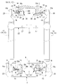
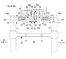
- FIG. 2 is a partially cutaway front view showing a passive link, a drive link and a movable member of the parallel link robot of FIG. 1
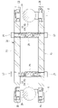
- FIG. FIG. 2 is a longitudinal sectional view showing a support link provided in the parallel link robot of FIG. 1
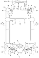
- FIG. 3 is a partially cutaway front view showing a replacement procedure of a ball joint between the passive link and the driving link of FIG. 2
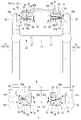
- FIG. 5 is a partially cutaway front view showing a state in which a passive link is removed from a drive link in the work of replacing the ball joint of FIG. 4 ; 1. It is the front view which broke a part which shows the 1st modification of the parallel link robot of FIG.
- a parallel link robot 1 according to a first embodiment of the present disclosure will be described below with reference to the drawings.
- a parallel link robot 1 according to this embodiment as shown in FIG. It has three arms 4, 5, 6 connecting the part 2 and the movable member 3 in parallel.
- the base portion 2 is provided with three servomotors (motors) 7, 8 and 9 for driving the three arms 4, 5 and 6, respectively.
- Each of the arms 4, 5 and 6 includes drive links 10, 11 and 12 which are driven to rotate about a horizontal rotation axis A by respective servo motors 7, 8 and 9, drive links 10, 11 and 12 and a movable member 3. and two parallel rod-shaped passive links 13, 14, 15 connecting the .
- the three drive links 10 , 11 , 12 are arranged at regular intervals around a center axis B extending vertically through the center of the base portion 2 .
- each passive link 13, 14, 15 is a ball joint 16 that rotatably connects the passive link 13, 14, 15 to the drive links 10, 11, 12 and the movable member 3, as shown in FIG. installed.
- the ball joint 16 has a ball stud 19 and a socket 20 .
- the ball stud 19 includes a ball 17 and a round bar-shaped stud (fixed portion) 18 extending radially outward from the outer surface of the ball 17 .
- the socket 20 has an inner spherical surface 16a that partially covers the outer peripheral surface of the ball 17, and supports the ball 17 so as to be movable around the center point. By rotating the ball 17 about a center point within the socket 20, the stud 18 can be tilted in any tilt direction.
- sockets 20 are fixed to both ends of the passive links 13, 14, 15, and the ball studs 19 are positioned within a predetermined angular range around the direction orthogonal to the longitudinal axis of the passive links 13, 14, 15. , is rotatably supported with respect to the passive links 13, 14, 15.
- a threaded hole (first threaded hole) 21 is provided in the end face of the stud 18 along the axial direction of the stud 18 .
- a support link 22 spans between the two passive links 13, 14, 15 of each arm 4, 5, 6, as shown in FIGS.
- the support links 22 are composed of two support plates 23 arranged on both sides of the two passive links 13, 14, 15 in the radial direction, and shafts 24 fixed to the passive links 13, 14, 15. and a bearing 25 for mounting the plate 23 rotatably around an axis C orthogonal to the longitudinal axes of the passive links 13, 14, 15.
- reference numeral 26 denotes a spacer adjusted to have an appropriate length to apply preload to the bearing 25
- reference numeral 27 denotes a bolt that attaches the spacer 26 between the two support plates 23.
- the support link 22 rotates relative to the passive links 13, 14, 15 as the two passive links 13, 14, 15 rotate relative to the drive links 10, 11, 12. Therefore, even if the passive links 13, 14, 15 are rotated with severe acceleration and deceleration with respect to the drive links 10, 11, 12, the two passive links 13, 14, 15 of each arm 4, 5, 6 are can be maintained parallel.
- each drive link 10, 11, 12 has two plate-like plates extending along a plane perpendicular to the axis of rotation A at positions where passive links 13, 14, 15 are attached.
- Mounting portions 28 are provided at intervals in the rotation axis A direction.
- each mounting portion 28 is provided with a through hole (second through hole) 29 extending coaxially in parallel with the rotation axis A.
- the distance between the outer surfaces of the two mounting portions 28 is the distance between the end surfaces of the ball studs 19 when the longitudinal axes of the ball studs 19 mounted on the two passive links 13, 14, 15 are aligned. is set equal to
- the ball studs 19 attached to the drive links 10, 11, 12 and the passive links 13, 14, 15 are passed through the through holes 29 of the attachment portions 28 of the drive links 10, 11, 12 from the inner side surface.
- the ball stud 19 is fixed by fastening a bolt member (screw member) 30 to the screw hole 21 of the ball stud 19 .
- the bolt member 30 has a fitting portion 30c that fits into the through hole 29 of the mounting portion 28 between the male screw 30a at one end and the head portion 30b at the other end. As a result, the ball stud 19 can be positioned and fixed to the mounting portion 28 of the drive links 10 , 11 , 12 .
- 3 sets of 6 passive links 13, 14, 15 are attached to positions radially outward from the outer peripheral surface.
- Three sets of six plate-like mounting portions 31 (two of which are shown in FIG. 2) extending along a plane parallel to the central axis D are provided.
- the two mounting portions 31 of each set are arranged parallel to each other with a gap in the tangential direction around the central axis D, and each have a through hole (second through hole) 32 coaxially extending in the tangential direction.
- the distance between the outer surfaces of the two mounting portions 31 is also the distance between the end surfaces of the ball studs 19 when the longitudinal axes of the ball studs 19 mounted on the two passive links 13, 14, 15 are aligned. is set equal to the interval of In this embodiment, a first screw hole 21 provided in the stud 18, second through holes 29 and 32 provided in the mounting portions 28 and 31 of the drive links 10, 11 and 12 or the movable member 3, and A mounting mechanism is constituted by a bolt member 30 that passes through the two through holes 29 and 32 and is fastened to the first screw hole 21 .
- the ball stud 19 attached to the movable member 3 and the passive links 13 , 14 , 15 is connected to the screw hole 21 of the ball stud 19 by inserting the bolt member 30 through the through hole 32 of the mounting portion 31 of the movable member 3 . It is fixed by fastening to The bolt member 30 has a fitting portion 30c that fits into the through hole 32 of the mounting portion 31 between the male screw 30a at one end and the head portion 30b at the other end. As a result, the ball stud 19 can be positioned and fixed to the mounting portion 31 of the movable member 3 .
- the parallel link robot 1 by synchronously driving the three servo motors 7, 8, and 9, the movable member 3 is held in a horizontal posture and moved to a desired three-dimensional position. It can be translated.
- a ball joint 16 connecting the drive links 10, 11, 12 and the passive links 13, 14, 15 and the passive links 13, 14, 15 and the movable member 3 is provided. is rotated frequently and repeatedly. Therefore, it is necessary to periodically check the state of the ball joint 16 and perform maintenance such as replacing it if it is worn.
- the drive links 10, 11, 12 and the passive links 13, 14, 15 are aligned along the outer surface of the mounting portion 28 as indicated by the arrow A as shown in FIG.
- the drive links 10, 11, 12 and the passive links 13, 14, 15 can be separated by relative movement in the direction.
- the ball joints 16 can be easily removed from the ends of the passive links 13, 14, 15 in a state separated from the drive links 10, 11, 12, and replaced with new ball joints 16.
- the parallel link robot 1 when replacing the ball joint 16 connecting the drive links 10, 11, 12 and the two passive links 13, 14, 15, the replacement There is no need to change the interval between the balls 17 of the two ball joints 16 to be attempted.
- the distance between the balls 17 of the two ball joints 16 connecting the drive links 10, 11, 12 and the two passive links 13, 14, 15 is the distance between the support link 22 and the movable member 3 and the two passive links 13, 14, 14, 15. It is fixed by two ball joints 16 connecting 15 . Since the intervals between the balls 17 are not changed at the time of replacement, the ball joint 16 can be replaced without large-scale work such as disassembling the support link 22 or removing the connection between the movable member 3 and the passive links 13, 14, 15. can be done.
- the distance between the balls 17 of the ball joint 16 connecting the movable member 3 and the passive links 13, 14, 15 is are fixed by two ball joints 16 connecting the Therefore, even when replacing the ball joints 16 between the movable member 3 and the passive links 13, 14, 15, the ball joints 16 between the drive links 10, 11, 12 and the passive links 13, 14, 15 In the same way as , it can be easily exchanged without large-scale work.
- the pair of passive links 13, 14, 15, the ball joints 16 attached to both ends of the passive links 13, 14, 15, the passive links 13, 14, 15 can be treated as a passive link unit (unit). That is, there is an advantage that it can be manufactured and managed as a passive link unit, and not only maintenance work but also assembly work can be facilitated.
- the mounting portions 28, 28 provided on the drive links 10, 11, 12 or the movable member 3 are provided.
- a fitting portion 30c of a bolt member 30 fastened to the screw hole 21 of the ball stud 19 is fitted into the through holes 29 and 32 of the ball stud 19.
- the stud 18 of the ball stud 19 is provided with a pin hole 33 parallel to the screw hole 21, and the mounting portions 28, 31 are provided with pin holes 34 parallel to the through holes 29, 32. may be provided.
- a conventional bolt 30 can be screwed into the threaded hole 21 of the stud 18 to secure the ball stud 19 to the drive links 10, 11, 12 or the movable member 3.
- the stud 18 is formed in a flat plate shape as shown in FIG. 10, 11, 12 or the movable member 3 may be fixed in a state of being stacked on the stud 18 in the plate thickness direction.
- the stud 18 is provided with a through hole (first through hole) 36 penetrating in the plate thickness direction and a pin hole 37 parallel to the through hole 36.
- a flat mounting portion 28 parallel to the axis A is provided with a screw hole (second screw hole) 38 extending in the plate thickness direction and a pin hole 39 .
- the bolt 30 passing through the through-hole 36 is fastened to the screw hole 38 of the mounting portion 28 while being positioned by the pin 40 fitted in the pin hole 37 of the stud 18 and the pin hole 39 of the mounting portion 28 .
- the ball stud 19 can be fixed to the drive links 10, 11, 12 or the movable member 3.
- a first through hole 36 provided in the stud 18 which is a fixed portion
- a second screw hole 38 provided in the drive links 10, 11, 12 or the mounting portions 28, 31 of the movable member 3
- the first A mounting mechanism is configured by the bolt member 30 that passes through the through hole 36 and is fastened to the second screw hole 38 .
- the parallel link robot 1 has the three arms 4, 5, and 6, it may have any number of arms of two or more instead. Also, regarding the case where the ball joint 16 connecting the drive links 10, 11, 12 and the passive links 13, 14, 15 and the ball joint 16 connecting the movable member 3 and the passive links 13, 14, 15 have the same structure. Although explained, it is not limited to this, and may be adopted for only one of them.
- the stud 18 has the screw hole 21 or the through hole 36.
- a structure including an adapter 43 having a screw hole 42 for fastening may be employed.
- the stud 18 and the adapter 43 serve as the fixing portion, and the adapter 43 may be provided with the through hole (first through hole) 44 and the pin hole 45 .
- the studs 18 of the ball joints 16 attached to the passive links 13, 14, 15 are separately provided for each of the passive links 13, 14, 15.
- a structure including two balls 17 and an integral stud (fixing part) 46 connecting the two balls 17 is adopted as the paired ball joint 16.
- the stud 46 is provided with one or more through holes (first through holes) 47 or screw holes (first screw holes, not shown) and one or more pin holes 48 .
- the passive link unit including the ball joint 16 can be removed from the drive links 10, 11, 12 and the movable member 3 without disassembling the support link 22.
- the socket 20 is removed from the passive links 13, 14, 15 in the longitudinal direction without rotating about the longitudinal axis of the passive links 13, 14, 15, two ball joints 16 and a single stud can be used. 18 can be replaced as an assembly unit. Alternatively, the ball joint 16 can be replaced by replacing the whole passive link unit.
Landscapes
- Engineering & Computer Science (AREA)
- Robotics (AREA)
- Mechanical Engineering (AREA)
- Manipulator (AREA)
Abstract
Description
駆動リンクと2本の受動リンクとの間、および2本の受動リンクと可動部との間は、それぞれボールジョイントによって回転可能に連結されている。
本実施形態に係るパラレルリンクロボット1は、図1に示されるように、天井あるいは架台に固定されるベース部2と、ベース部2の下方に間隔をあけて配置される可動部材3と、ベース部2と可動部材3とを並列に接続する3本のアーム4,5,6とを備えている。
各アーム4,5,6は、各サーボモータ7,8,9によって水平な回転軸線A回りに回転駆動される駆動リンク10,11,12と、駆動リンク10,11,12と可動部材3とを連結する2本の平行な棒状の受動リンク13,14,15とを備えている。3つの駆動リンク10,11,12は、ベース部2の中心を鉛直方向に延びる中心軸線B回りに等間隔に配置されている。
スタッド18の端面には、スタッド18の軸方向に沿ってネジ孔(第1ネジ孔)21が設けられている。
図中、符号26は、ベアリング25に予圧を与えるために適正な長さに調整されたスペーサ、符号27は、スペーサ26を2つのサポートプレート23間に取り付けるボルトである。
本実施形態に係るパラレルリンクロボット1によれば、3つのサーボモータ7,8,9を同期して駆動することにより、可動部材3を、水平な姿勢に保持させつつ、所望の3次元位置に並進移動させることができる。
ボルト部材30の取り外しの際には、ボルト部材30を駆動リンク10,11,12の取付部28の内側面側に抜き出す方向に移動させて取り外すので、2つのボールスタッド19のボール17間隔を変化させずにボルト部材30を取り外すことができる。
すなわち、受動リンクユニットとして製造し、管理しておくことができ、保守作業のみならず、組み立て作業も容易にすることができるという利点がある。
また、駆動リンク10,11,12と受動リンク13,14,15を連結するボールジョイント16および可動部材3と受動リンク13,14,15とを連結するボールジョイント16が同等の構造を有する場合について説明したが、これに限定されるものではなく、いずれか一方のみに採用してもよい。
2 ベース部
3 可動部材
4,5,6 アーム
7,8,9 サーボモータ(モータ)
10,11,12 駆動リンク
13,14,15 受動リンク
16 ボールジョイント
17 ボール
18,46 スタッド(固定部)
21 ネジ孔(第1ネジ孔)
22 サポートリンク
29,32 貫通孔(第2貫通孔)
30 ボルト部材(ネジ部材)
36,44,47 貫通孔(第1貫通孔)
38 ネジ孔(第2ネジ孔)
43 アダプタ(固定部)
C 軸線
Claims (4)
- ベース部と、
該ベース部に対して間隔をあけて配置される可動部材と、
前記ベース部と前記可動部材とを並列に接続する複数のアームとを備え、
各該アームが、前記ベース部に設置されたモータによって回転駆動される駆動リンクと、該駆動リンクと前記可動部材とを連結する2本の平行な受動リンクと、各該受動リンクと前記駆動リンクとの間および各前記受動リンクと前記可動部材との間に配置されるボールジョイントと、各該ボールジョイントを前記駆動リンクまたは前記可動部材に着脱可能に取り付ける取付機構とを備え、
各前記ボールジョイントが、ボールと、該ボールに一体的に設けられた固定部とを備え、
各前記アームの各前記受動リンクと前記駆動リンクとの間および各前記受動リンクと前記可動部材との間の少なくとも一方の前記取付機構が、前記固定部に設けられた第1ネジ孔または第1貫通孔と、前記駆動リンクまたは前記可動部材に設けられた第2貫通孔または第2ネジ孔と、前記第1貫通孔を貫通して前記第2ネジ孔に締結、または、前記第2貫通孔を貫通して前記第1ネジ孔に締結されるネジ部材とを備えるパラレルリンクロボット。 - 各前記アームの各前記受動リンクと前記駆動リンクとの間および各前記受動リンクと前記可動部材との間の少なくとも一方に配置される2個の前記ボールジョイントの前記固定部が一体的に構成されている請求項1に記載のパラレルリンクロボット。
- 各前記アームの2本の前記受動リンク間に掛け渡され、2本の前記受動リンクを連結するサポートリンクを備え、
該サポートリンクが、各前記受動リンクに、該受動リンクの長手軸に直交する軸線回りに回転可能に取り付けられている請求項1または請求項2に記載のパラレルリンクロボット。 - 両端に前記ボールジョイントを取り付けた2本の前記受動リンクが、前記サポートリンクによって連結されたユニットとして、前記駆動リンクおよび前記可動部材に着脱可能に取り付けられている請求項3に記載のパラレルリンクロボット。
Priority Applications (4)
| Application Number | Priority Date | Filing Date | Title |
|---|---|---|---|
| DE112022000669.2T DE112022000669T5 (de) | 2021-03-30 | 2022-03-24 | Parallelroboter |
| CN202280023741.4A CN117042934A (zh) | 2021-03-30 | 2022-03-24 | 并联连杆机器人 |
| US18/546,946 US12220815B2 (en) | 2021-03-30 | 2022-03-24 | Parallel link robot |
| JP2023511110A JP7708846B2 (ja) | 2021-03-30 | 2022-03-24 | パラレルリンクロボット |
Applications Claiming Priority (2)
| Application Number | Priority Date | Filing Date | Title |
|---|---|---|---|
| JP2021-057765 | 2021-03-30 | ||
| JP2021057765 | 2021-03-30 |
Publications (1)
| Publication Number | Publication Date |
|---|---|
| WO2022210243A1 true WO2022210243A1 (ja) | 2022-10-06 |
Family
ID=83458760
Family Applications (1)
| Application Number | Title | Priority Date | Filing Date |
|---|---|---|---|
| PCT/JP2022/013869 Ceased WO2022210243A1 (ja) | 2021-03-30 | 2022-03-24 | パラレルリンクロボット |
Country Status (6)
| Country | Link |
|---|---|
| US (1) | US12220815B2 (ja) |
| JP (1) | JP7708846B2 (ja) |
| CN (1) | CN117042934A (ja) |
| DE (1) | DE112022000669T5 (ja) |
| TW (1) | TW202237352A (ja) |
| WO (1) | WO2022210243A1 (ja) |
Cited By (1)
| Publication number | Priority date | Publication date | Assignee | Title |
|---|---|---|---|---|
| US12090657B2 (en) | 2021-04-30 | 2024-09-17 | Fanuc Corporation | Parallel link robot |
Citations (2)
| Publication number | Priority date | Publication date | Assignee | Title |
|---|---|---|---|---|
| JP2019038051A (ja) * | 2017-08-23 | 2019-03-14 | ファナック株式会社 | ロボットおよびパラレルリンクロボット |
| JP2020180633A (ja) * | 2019-04-24 | 2020-11-05 | ファナック株式会社 | ブーツシール、ロボットおよびパラレルリンクロボット |
Family Cites Families (10)
| Publication number | Priority date | Publication date | Assignee | Title |
|---|---|---|---|---|
| DE102007004379A1 (de) * | 2007-01-29 | 2008-07-31 | Robert Bosch Gmbh | Vorrichtung zum Bewegen und Positionieren eines Gegenstandes im Raum |
| JP2010207967A (ja) | 2009-03-10 | 2010-09-24 | Olympus Corp | パラレルリンクステージの調整方法、基準位置決め治具、およびパラレルリンクステージ |
| JP5977137B2 (ja) | 2012-10-04 | 2016-08-24 | ヤマハ発動機株式会社 | 回転軸およびこの回転軸を備える産業用ロボット |
| DE102017211642A1 (de) * | 2017-07-07 | 2019-01-10 | Kuka Deutschland Gmbh | Delta-Roboter |
| CN108001560B (zh) * | 2017-12-19 | 2023-09-19 | 浙江工业大学 | 一种六自由度四足机器人 |
| JP6691147B2 (ja) | 2018-01-09 | 2020-04-28 | ファナック株式会社 | パラレルリンクロボット |
| JP6836560B2 (ja) * | 2018-09-12 | 2021-03-03 | ファナック株式会社 | 関節カバー、ロボットおよびパラレルリンクロボット |
| CN110076755B (zh) * | 2019-05-06 | 2021-01-26 | 燕山大学 | 三自由度运动模拟器 |
| JP7332337B2 (ja) * | 2019-05-27 | 2023-08-23 | ファナック株式会社 | パラレルリンクロボット |
| CN210452713U (zh) * | 2019-06-14 | 2020-05-05 | 江苏信息职业技术学院 | 一种三轴机械手臂 |
-
2022
- 2022-03-24 WO PCT/JP2022/013869 patent/WO2022210243A1/ja not_active Ceased
- 2022-03-24 US US18/546,946 patent/US12220815B2/en active Active
- 2022-03-24 DE DE112022000669.2T patent/DE112022000669T5/de active Pending
- 2022-03-24 CN CN202280023741.4A patent/CN117042934A/zh active Pending
- 2022-03-24 JP JP2023511110A patent/JP7708846B2/ja active Active
- 2022-03-25 TW TW111111495A patent/TW202237352A/zh unknown
Patent Citations (2)
| Publication number | Priority date | Publication date | Assignee | Title |
|---|---|---|---|---|
| JP2019038051A (ja) * | 2017-08-23 | 2019-03-14 | ファナック株式会社 | ロボットおよびパラレルリンクロボット |
| JP2020180633A (ja) * | 2019-04-24 | 2020-11-05 | ファナック株式会社 | ブーツシール、ロボットおよびパラレルリンクロボット |
Cited By (1)
| Publication number | Priority date | Publication date | Assignee | Title |
|---|---|---|---|---|
| US12090657B2 (en) | 2021-04-30 | 2024-09-17 | Fanuc Corporation | Parallel link robot |
Also Published As
| Publication number | Publication date |
|---|---|
| JPWO2022210243A1 (ja) | 2022-10-06 |
| US20240227171A9 (en) | 2024-07-11 |
| TW202237352A (zh) | 2022-10-01 |
| DE112022000669T5 (de) | 2024-03-07 |
| US20240131692A1 (en) | 2024-04-25 |
| US12220815B2 (en) | 2025-02-11 |
| JP7708846B2 (ja) | 2025-07-15 |
| CN117042934A (zh) | 2023-11-10 |
Similar Documents
| Publication | Publication Date | Title |
|---|---|---|
| JP6289973B2 (ja) | パラレルリンク機構およびリンク作動装置 | |
| KR102507045B1 (ko) | 탄성 압축성 프리텐셔닝 요소를 갖는 로봇용 조인트 베어링 | |
| US10022827B2 (en) | Method for initially setting position of origin of link actuators, and link actuator | |
| US10427294B2 (en) | Parallel link robot and parallel link structure | |
| US10780574B2 (en) | Link actuating device | |
| JP5535396B2 (ja) | リニアアクチュエータ | |
| JP2014061571A (ja) | ユニバーサルジョイント、及びそれを備えたパラレルリンクロボット | |
| WO2022210243A1 (ja) | パラレルリンクロボット | |
| CN118990604A (zh) | 手臂与躯干的连接结构、装配结构、人形机器人及机器人 | |
| JPS626958B2 (ja) | ||
| CN108908395B (zh) | 一种用于机器人力控的多方向被动柔顺装置 | |
| JP2011230241A (ja) | パラレルリンクロボット | |
| CN117337227A (zh) | 并联连杆机器人 | |
| WO2023187978A1 (ja) | パラレルリンクロボット | |
| JP2015224782A (ja) | パラレルリンク機構およびリンク作動装置 | |
| US12296465B2 (en) | Parallel link robot and robot system | |
| CN223098399U (zh) | 一种具备便捷拆卸功能的夹头快换组件 | |
| US20250214228A1 (en) | Coupling structure and parallel link robot | |
| WO2026070522A1 (ja) | パラレルリンク機構およびリンク作動装置 | |
| WO2023175949A1 (ja) | パラレルリンクロボット及びパラレルリンクロボットシステム | |
| JP2005256952A (ja) | リンク作動装置 | |
| JP2025066479A (ja) | パラレルリンク機構およびリンク作動装置 | |
| US20210197364A1 (en) | Support structure, robot and parallel link robot | |
| JPWO2024247095A5 (ja) | ||
| JP4710425B2 (ja) | トロイダル式無段変速機の位置決め方法およびその装置 |
Legal Events
| Date | Code | Title | Description |
|---|---|---|---|
| 121 | Ep: the epo has been informed by wipo that ep was designated in this application |
Ref document number: 22780457 Country of ref document: EP Kind code of ref document: A1 |
|
| ENP | Entry into the national phase |
Ref document number: 2023511110 Country of ref document: JP Kind code of ref document: A |
|
| WWE | Wipo information: entry into national phase |
Ref document number: 18546946 Country of ref document: US |
|
| WWE | Wipo information: entry into national phase |
Ref document number: 112022000669 Country of ref document: DE |
|
| WWE | Wipo information: entry into national phase |
Ref document number: 202280023741.4 Country of ref document: CN |
|
| 122 | Ep: pct application non-entry in european phase |
Ref document number: 22780457 Country of ref document: EP Kind code of ref document: A1 |