WO2022210239A1 - 配管構造 - Google Patents
配管構造 Download PDFInfo
- Publication number
- WO2022210239A1 WO2022210239A1 PCT/JP2022/013861 JP2022013861W WO2022210239A1 WO 2022210239 A1 WO2022210239 A1 WO 2022210239A1 JP 2022013861 W JP2022013861 W JP 2022013861W WO 2022210239 A1 WO2022210239 A1 WO 2022210239A1
- Authority
- WO
- WIPO (PCT)
- Prior art keywords
- pipe
- boss portion
- peripheral surface
- tip
- bulge
- Prior art date
- Legal status (The legal status is an assumption and is not a legal conclusion. Google has not performed a legal analysis and makes no representation as to the accuracy of the status listed.)
- Ceased
Links
Images

Classifications
-
- F—MECHANICAL ENGINEERING; LIGHTING; HEATING; WEAPONS; BLASTING
- F16—ENGINEERING ELEMENTS AND UNITS; GENERAL MEASURES FOR PRODUCING AND MAINTAINING EFFECTIVE FUNCTIONING OF MACHINES OR INSTALLATIONS; THERMAL INSULATION IN GENERAL
- F16L—PIPES; JOINTS OR FITTINGS FOR PIPES; SUPPORTS FOR PIPES, CABLES OR PROTECTIVE TUBING; MEANS FOR THERMAL INSULATION IN GENERAL
- F16L23/00—Flanged joints
- F16L23/02—Flanged joints the flanges being connected by members tensioned axially
Definitions
- the present disclosure relates to a piping structure, and more particularly, to a piping structure including piping and a boss for assembling the piping.
- the pipes arranged along the wall surface of the engine are fixed by inserting screws such as bolts into the bosses (also called welding nuts) that are connected to the top and bottom of the pipes. If the boss is separated from the pipe in order to maintain the shape of the pipe, the boss may interfere with other parts. However, considering the fastening operation using screws such as bolts, the distance between the outer peripheral surface of the pipe and the outer peripheral surface of the boss portion cannot be increased.
- An object of the present disclosure is to provide a piping structure that prevents fluid from accumulating inside while avoiding interference with surrounding parts.
- a piping structure that achieves the above object includes a pipe arranged along a wall surface, and a pipe arranged below the pipe and protruding from the wall surface in a direction intersecting with the axial direction of the pipe. and a boss into which a screw is inserted from the tip thereof, wherein a portion of the lower part of the pipe located immediately above the tip of the boss and the tip of the pipe are integrated and overlapped,
- the protrusion length from the wall surface to the tip of the boss portion is such that the tip exceeds the lowest point on the inner peripheral surface of the pipe located directly above the boss portion and is farthest apart from the lowest point in the orthogonal direction.
- the lower part of the pipe is a weir part having a convex bulge from the outer side to the inner side in the pipe radial direction with the lowest point as a boundary. and a roundabout portion in which the pipe wall forms a convex arc from the inner side to the outer side in the pipe radial direction.
- the piping and the boss portion are integrated and overlapped, so that the piping and the boss portion are close to each other, and interference with peripheral components can be avoided. Furthermore, according to one aspect of the present disclosure, a portion where the shape of the pipe is changed and a portion where the shape of the pipe is not changed due to the close proximity of the pipe and the boss exist on the boundary of the lowest point of the pipe. Therefore, since the fluid that tries to stay in the part whose shape has been changed flows into the part that has not been changed, it is possible to avoid the fluid from accumulating inside the pipe.
- FIG. 1 is a perspective view illustrating the piping structure of the embodiment.
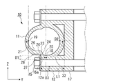
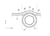
- FIG. 2 is an enlarged cross-sectional view of the hatched cross section in FIG. 3 is a cross-sectional view of the bulge in FIG. 1 in the XZ plane.
- the X direction is the pipe axis direction of the pipe 11
- the Y direction is the direction perpendicular to the pipe axis direction of the pipe 11
- the axial direction of each of the bosses 12 to 14 and the bolt 15 and the Z direction is the vertical direction. respectively.
- the white arrows in the figure indicate the flow of the recirculated exhaust.
- the dimensions of the members are changed so that the configuration is easy to understand, and they do not necessarily match those actually manufactured.
- screw refers to a male screw having a helical groove on the side surface of a cylindrical body.
- bolts 15 are employed as screws.
- the holes of the bosses 12 to 14 into which the screws are inserted are formed with spiral grooves directly on the cylindrical surface and have female threads to be screwed with the male threads, unless otherwise specified.
- a nut having an opening formed with an internal thread that engages with the external thread is shown fitted in the central portion.
- the piping structure 10 of the embodiment is assembled to the side of the engine by screwing bolts 15 onto bosses 12 to 14 of a piping 11 that constitutes part of an exhaust gas recirculation passage of an engine (not shown). It is.
- the exhaust gas recirculation passage is a passage for recirculating exhaust gas from an exhaust passage (not shown) to the intake passage.
- the recirculated exhaust gas flowing through the exhaust gas recirculation passage passes through the communication pipe 1 branched from the exhaust passage (not shown) and the flow rate control valve 2 and flows through the curved pipe 16 and the pipe 11 in this order.
- the communication pipe 1 slopes downward toward the flow control valve 2 .
- the flow control valve 2 is configured with a butterfly valve (not shown).
- the piping structure 10 comprises a piping 11, bosses 12-14, a bent piping 16, and a flange 17.
- the pipe 11 is composed of a circular pipe extending in the X direction, and its tip communicates with a curved pipe 16 indicated by a dotted line in the drawing.
- Bosses 12-14 protrude from flange 17 in the Y direction.
- the boss portions 12 to 14 form a cylindrical cylindrical body when viewed in the X direction.
- a bolt 15 is inserted from the tip of each of the bosses 12 to 14 .
- Bosses 12 to 14 surround the tip of bent pipe 16 .
- the boss portion 12 is arranged directly below the pipe 11, the boss portion 13 is arranged directly above the pipe 11, and the boss portion 14 is arranged elsewhere.
- the flange 17 has a plate-like shape projecting radially from the entire periphery of the tip of the curved pipe 16 .
- the wall surface is the surface with which the outer peripheral surface of the pipe 11 is in contact, and indicates the surface from which the boss portions 12 to 14 protrude.
- the wall surface is the surface facing the front side of the flange 17 in the Y direction.
- a dam portion 21 having 20 formed thereon and a detour portion 22 are arranged side by side.
- the lower part of the pipe 11 indicates the lower part in the Z direction of the pipe 11, and the tip part of the boss part 12 indicates the left part in the Y direction including the tip 12a.
- the part of the lower portion of the pipe 11 is a portion located directly above the tip of the boss portion 12 .
- integration indicates a state in which each member is seamlessly connected.
- the piping structure 10 of this embodiment is constructed by integrating the piping 11, the boss portions 12 to 14, the bent piping 16, and the flange 17, respectively.
- a portion of the lower portion of the pipe 11 and the tip portion of the boss portion 12 are integrated and overlapped means that the minimum value D1 of the thickness in the pipe radial direction of the integrated and overlapped portion is affected by the integration. It shows a state in which the thickness D2 of the pipe 11 and the ring width D3 of the boss portion 12 are smaller than the sum of the thickness D2 of the pipe 11 and the ring width D3 of the boss portion 12.
- the integrally overlapped portion becomes a shared portion of the pipe 11 and the boss portion 12, and has an inner peripheral surface of the pipe 11, a tip 12a of the boss portion 12, and a portion into which the bolt 15 of the boss portion 12 is inserted. .
- the minimum value D1 can be reduced to the larger value of the pipe thickness D2 and the ring width D3.
- the ring width D3 is adopted as the minimum value D1.
- the lowest point 18 is a point that indicates the lowest portion on the inner peripheral surface of the pipe 11 directly above the boss portion 12 in a cross-sectional view on the YZ plane.
- the lowest point 18 is a point that indicates the lowest position when the engine with the piping structure 10 is mounted on the vehicle.
- the most lateral point 19 is a point that indicates a portion located farthest in the Y direction from the lowest point 18 on the inner peripheral surface of the pipe 11 directly above the boss portion 12 in a cross-sectional view on the YZ plane, and is located on the leftmost side in the drawing. It is a point that indicates the site where it is located.
- the bulge 20 is formed by the pipe wall of the pipe 11 protruding from the outside in the pipe radial direction to the inside.
- the pipe wall of the pipe 11 on which the bulge 20 is formed has a convex inner peripheral surface and a concave outer peripheral surface.
- the inner peripheral surface of the pipe 11 on which the bulge 20 is formed has a shape obtained by rotating an ellipse whose long axis is directed in the X direction around the long axis and halving a spheroid by a plane passing through the long axis. form.
- the bulge-formed outer peripheral surface forms a shape along the space so that the space forming a cylindrical body whose column axis direction is oriented in the X direction is held at the tip 12a of the boss portion 12 .
- the bulge 20 has an apex 23, a first slope 24, an end 25 of the first slope 24, and a second slope 26 on its inner peripheral surface.
- Bulge 20 has a flat surface 27 and a curved surface 28 on its outer peripheral surface.
- the bulge 20 is formed by integrally overlapping the lower portion of the pipe 11 and the tip of the boss portion 12 with respect to the inner peripheral surface of other parts, and the protrusion length L1 of the boss portion 12 is such that the tip 12a is the lowest point 18 , and a length that does not exceed the most lateral point 19 of the pipe 11 .
- the bulge 20 is formed by forming a depression 20 on the outer peripheral surface of the pipe 11 to secure a space for fastening the bolt 15 .
- the projection length L1 is the length from the left side of the flange 17 in the Y direction to the tip 12a of the boss portion 12.
- a position beyond the lowest point 18 is a position beyond a vertical line on the YZ plane passing through the lowest point 18 .
- a position not exceeding the sidemost point 19 is a position not exceeding a vertical line on the YZ plane passing through the sidemost point 19 .
- a vertex 23 indicates a portion of the inner peripheral surface of the bulge 20 that is located furthest inside the pipe 11 .
- the first slope 24 is the inner peripheral surface of the pipe 11 on which the bulge 20 is formed, and is a surface that slopes downward from the vertex 23 toward the lowest point 18 side terminal 25 of the terminal ends of the bulge 20 .
- the first slope 24 is a surface of a shape obtained by further cutting a halved spheroid along a plane passing through the major axis. As shown in the drawing, the first slope 24 is a surface that slopes downward from the vertex 23 toward the lowest point 18 in a cross section on the YZ plane passing through the vertex 23 .
- a terminal end 25 of the first slope 24 is arranged before the lowest point 18 .
- the first slope 24 is the inner peripheral surface of the pipe 11 on which the bulge 20 is formed, and is a slope formed by the inner peripheral surface protruding from the outer side to the inner side in the pipe radial direction.
- the inner peripheral surface of another pipe 11 without the bulge 20 is a cylindrical surface formed by denting from the inner side to the outer side in the pipe radial direction.
- a terminal end 25 of the first slope 24 is a boundary between a portion where the inner peripheral surface of the pipe 11 protrudes toward the inside and a portion where the inner peripheral surface is recessed toward the outside.
- the second slope 26 is the inner peripheral surface of the pipe 11 on which the bulge 20 is formed. It is a surface that slopes downward from the opposite end to the vertex 23 .
- the second slope 26 is a surface of a shape obtained by further cutting the halved spheroid by a plane passing through the major axis. As shown in the drawing, the second slope 26 is a surface that slopes downward toward the vertex 23 in a cross section on the YZ plane passing through the vertex 23 .
- the weir portion 21 has a second slope 26 and a first slope 24 arranged in the pipe circumferential direction toward the lowest point 18 .
- the weir portion 21 forms a slope that slopes downward toward the lowest point 18 over the entire inner peripheral surface.
- the slope similarly slopes downward toward the lowest point 18 .
- the flat surface 27 is the outer peripheral surface of the pipe 11 on which the bulge 20 is formed, and is a flat surface perpendicular to the X direction.
- the flat surface 27 constitutes part of the tip 12 a of the boss portion 12 .
- the flat surface 27 is a surface that comes into contact with the bearing surface 15 a of the bolt 15 when the bolt 15 is inserted into the boss portion 12 .
- the curved surface 28 is the outer peripheral surface of the pipe 11 on which the bulge 20 is formed, and forms a convex cylindrical surface from the bottom to the top in the Z direction.
- the curved surface 28 is a surface that does not protrude inside the space of the cylindrical body that is formed ahead of the tip 12a of the boss portion 12 . In other words, the curved surface 28 does not interfere with the bolt 15 that is inserted into and removed from the boss portion 12 .
- the opening area of the pipe 11 in the section on the YZ plane where the bulge 20 is formed is equal to the opening area in the section on the YZ plane where the bulge 20 is not formed.
- the opening on the right side of the vertical line passing through the lowest point 18 has a semicircular shape, and the area of the opening is equal to the area of the semicircle.
- the opening shape on the left side of the drawing from the vertical line passing through the lowest point 18 has a bulge 20 formed, and the vicinity of the most lateral point 19 bulges from the inner side to the outer side in the pipe radial direction.
- the opening area is equal to the opening area on the right side of the vertical line passing through the lowest point 18 in the figure.
- the inner peripheral surface of the pipe 11 on which the bulge 20 is formed is streamlined in the X direction.
- the streamlined shape indicates a shape in which the flow of fluid flowing in the X direction inside the pipe 11 is not blocked.
- the inner peripheral surface on which the bulge 20 of the present embodiment is formed has the shape of a spheroid divided in half, and slopes downward from the vertex 23 toward the terminal end 29 of the bulge 20 .
- the distance between the ends 29 of the bulge 20 on the XZ plane is longer than the diameter of the boss portion 12 , and the ends 29 are positioned outside the outer periphery of the boss portion 12 .
- the lower portion of the pipe 11 and the tip portion of the boss portion 12 are integrated and overlapped, so that the pipe 11 and the boss portion 12 can be brought closer to each other. Therefore, interference with peripheral components can be avoided.
- the weir portion 21 that changes the shape of the pipe 11 and the detour portion 22 that does not change the shape, which are generated by bringing the pipe 11 and the boss portion 12 close to each other are located at the bottom of the pipe 11. It exists with the point 18 as a boundary. Therefore, the fluid that tries to stay in the weir portion 21 flows into the detour portion 22 , so that it is possible to prevent the fluid from accumulating inside the pipe 11 .
- Condensed water which is obtained by condensing water contained in the recirculated exhaust gas, flows toward the flow control valve 2 along the communication pipe 1 inclined downward, passes through the flow control valve 2, and flows into the bent pipe 16 and the pipe 11.
- the condensed water that has passed through the curved pipe 16 flows into the lowest point 18 of the pipe 11 avoiding the bulge 20 without being hindered even if it collides with the tip of the bulge 20 of the pipe 11. ⁇ In this way, since it is possible to avoid accumulation of condensed water, corrosion of the inside of the pipe 11 due to condensed water can be suppressed.
- the piping 11 and the boss portion 12 are brought close to each other, and the piping 11 has a shape close to that of a cylindrical pipe.
- the target device can be installed in the middle of the piping.
- the device intended for the shape of the cylindrical pipe is the flow control valve 2 with a built-in butterfly valve.
- the protruding length L1 When the protruding length L1 is such that the tip 12a is arranged at a position not exceeding the lowest point 18, in order to secure a space for fastening the bolt 15, the lower part of the pipe 11 including the lowest point 18 is required. It is necessary to deform most of the inner peripheral surface upward. Therefore, the deformed portion acts as a weir against the upstream portion, and the condensed water flowing from the curved pipe 16 is accumulated. Further, when the protruding length L1 is such that the tip 12a is arranged at a position exceeding the sidemost point 19, the lengths of the bolt 15 and the boss portion 12 in the Y direction are extended. Therefore, the weight increases by the amount of extension. Further, the elongated boss portion becomes longer than the other boss portion 14 not integrated with the pipe 11, so that the common bolt 15 cannot be used for each of the boss portions 12 to 14. - ⁇
- the protruding length L1 of the boss portion 12 is set to a length such that the tip 12a exceeds the lowest point 18 and does not exceed the most lateral point 19 .
- the protruding length L1 of the boss portion 12 is set to a length such that the tip 12a exceeds the lowest point 18 and does not exceed the most lateral point 19 .
- an increase in the weight of the piping structure 10 can be suppressed.
- a common bolt 15 can be used for each boss 12-14.
- the protruding length L1 is the length at which the tip 12a is arranged at a position on the lowest point 18 side of the vertical line passing through the midpoint between the vertical line passing through the lowest point 18 and the vertical line passing through the most lateral point 19. more preferred. As a result, the lengths of the bolt 15 and the boss portion 12 are shortened, which is advantageous for weight reduction.
- the inner peripheral surface of the pipe 11 on which the bulge 20 is formed preferably has a first slope 24 that slopes downward from the vertex 23 of the bulge 20 toward the terminal end 25 on the lowest point 18 side.
- the terminal end 25 of the first slope 24 on the side of the lowest point 18 be positioned before the lowest point 18 .
- the inner peripheral surface of the pipe 11 from the terminal end 25 to the lowest point 18 extends from the inner side to the outer side in the pipe radial direction similarly to the detour portion 22 . becomes a convex cylindrical surface.
- the terminal end 25 is positioned at the lowest point 18 , the condensed water that has flowed into the pipe 11 may be blocked by the weir section 21 and may not flow into the detour section 22 . Therefore, by positioning the terminal end 25 before the lowest point 18 , it is possible to reliably flow the condensed water to the detour portion 22 . Since the terminal end 25 is positioned in front of the lowest point 18 on the YZ plane passing through the vertex 23 , the terminal ends 25 before and after the X direction are positioned further in front of the lowest point 18 .
- the weir portion 21 has a slope that slopes downward toward the lowest point 18 over the entire inner peripheral surface of the pipe 11 . As a result, even if the condensed water collides vigorously with the tip of the bulge 20 and rides on the bulge 20, the condensed water that rides on the bulge 20 flows toward the lowest point 18 due to the slope. As a result, a state in which condensed water accumulates in the weir portion 21 can be avoided.
- the inner peripheral surface of the pipe 11 on which the bulge 20 is formed is preferably streamlined in the X direction.
- the streamlined shape of the inwardly protruding portion allows the condensed water to flow smoothly and reduces resistance to the recirculated exhaust gas.
- the piping structure 10 of the present disclosure is not limited to a specific embodiment, and various modifications and changes are possible within the scope of the gist of the present disclosure.
- the piping structure 10 of the present disclosure is not limited to piping in which the piping 11 constitutes a part of the exhaust gas recirculation passage, but can be applied to piping through which a fluid that causes corrosion of the inside of the piping 11 flows.
- an exhaust manifold is exemplified as such piping.
- the piping structure 10 is not limited to being mounted on an engine, and can be applied to other engines such as a boiler as long as the boss portion for attaching the piping to the wall surface is positioned below the piping. .
- the piping structure 10 is configured with a pipe 11 and a boss portion 12 arranged below this pipe 11, other boss portions 13, 14, bent pipe 16, and flange 17 exemplified in the embodiment can be used. is not necessarily required.
- the shape of the outer circumference is not particularly limited.
- the axial direction of the bolt 15 inserted into and removed from the boss portion 12 is not limited to the direction perpendicular to the pipe axis direction of the pipe 11, and any direction that intersects the pipe axis direction can be applied.
- the protrusion length of the boss portion 13 is the same as that of the boss portion 12 .
- the upper part of the piping 11 has a portion where the pipe wall protrudes from the outer side to the inner side in the pipe radial direction and the pipe wall protrudes from the inner side to the outer side in the pipe radial direction. , and the arc-shaped portion of .
- the boss portion 13 arranged above the pipe 11 is also brought close to the pipe 11 like the boss portion 12 .
- the bulge formed by integrating and overlapping the pipe 11 and the boss portion 13 does not accumulate condensed water, so the shape is not particularly limited.
- the shape of the bulge 20 is limited to the shape of the embodiment as long as the tip disposed on the upstream side with respect to the flow of the fluid flowing through the pipe 11 does not block the fluid and the shape facilitates removal of the casting core. not something.
- the shape of the bulge 20 is a semi-cylindrical shape in which the column axis direction is directed to the pipe axis direction, and the semicircular tip surface is inclined toward the lowest point 18 when viewed from the inside to the outside in the pipe radial direction. are exemplified.
- the end of the bulge 20 does not collide with the fluid, and the shape of that portion is not particularly limited.
- the inner peripheral surface of the pipe 11 on which the bulge 20 is formed is desirably formed with a curved surface, but it does not have to be formed with a curved surface as long as the above conditions are satisfied.
- the piping structure according to the present disclosure prevents fluid from accumulating inside while avoiding interference with surrounding components.
Landscapes
- Engineering & Computer Science (AREA)
- General Engineering & Computer Science (AREA)
- Mechanical Engineering (AREA)
- Flanged Joints, Insulating Joints, And Other Joints (AREA)
- Rigid Pipes And Flexible Pipes (AREA)
Abstract
配管11とボルト15が挿入されるボス部12とを備える配管構造10において、ボス部12の先端部の直上に位置する配管11の下部の一部とその先端部とが一体化されて重なり、ボス部12の突出長L1は、先端12aが配管11の内周面における最下点18を超えるとともに最側点19を超えない位置に配置される長さであり、配管11の下部は、最下点18を境にして管壁が管径方向外側から内側に向かって凸の膨らみ20を有する堰部21と、管壁が管径方向内側から外側に向かって凸の弧状を成す迂回部22とが並ぶ構造である。
Description
本開示は、配管構造に関し、より詳細には、配管とその配管を組み付けるボス部とを備えた配管構造に関する。
EGR通路(排気再循環通路)の中途位置に凝縮水が溜まると、排気成分を含有する凝縮水によりEGR通路を構成する配管が腐食することが知られている。これに関して、EGR通路を上流側から下流側に向かって下方に傾斜させて中途位置に凝縮水が溜まることを回避する技術が開示されている(例えば、特許文献1参照)。
ところで、エンジンの壁面に沿って配置される配管は、配管の上下に連結させたボス部(溶接ナットともいう)にボルトなどのねじが挿入されて固定されている。配管の形状を維持するために配管からボス部を離間させるとボス部が他の部品と干渉するおそれがあるため、配管とボス部と間は極力近接させることが望ましい。しかしながら、ボルトなどのねじによる締結作業を考慮すると、配管の外周面とボス部の外周面とが接する距離までしか近接させることができない。
一方、他の部品との干渉を避けるために、配管の形状を変更してボス部どうしの間の距離を短くすることは可能である。しかし、ボス部の周辺の配管の形状のみを変更すると、その部分を境にして前後の配管の形状と異なる形状になる。それ故、その境の部分に凝縮水が溜まるおそれがある。また、その境の部分の形状を配管の全体の形状に適用するにはコストが高くなることに加えて、円筒管の形状を対象とした装置を配管の中途位置に組み込むことができなくなる。
本開示の目的は、周囲部品との干渉を避けつつ、内部に流体が溜まることを防ぐ配管構造を提供することである。
上記の目的を達成する本開示の一態様の配管構造は、壁面に沿って配置された配管と、この配管の下方に配置されるとともに前記壁面から前記配管の管軸方向に交差する方向に突出して、その先端からねじが挿入されるボス部とを備える配管構造において、前記ボス部の先端部の直上に位置する前記配管の下部の一部とその先端部とが一体化されて重なり、前記ボス部の前記壁面から前記先端までの突出長は、前記先端が前記ボス部の直上に位置する前記配管の内周面における最下点を超えるとともに前記最下点から前記直交する方向に最も離間した最側点を超えない位置に配置される長さであり、前記配管の下部は、前記最下点を境にして管壁が管径方向外側から内側に向かって凸の膨らみを有する堰部と、管壁が管径方向内側から外側に向かって凸の弧状を成す迂回部とが並ぶことを特徴とする。
本開示の一態様によれば、配管とボス部とが一体化して重なることで、配管とボス部とが近接し、周辺部品への干渉を回避することができる。さらに、本開示の一態様によれば、配管とボス部とが近接することで生じる配管の形状を変更した部位と変更しない部位とが配管の最下点を境にして存在する。それ故、形状を変更した部位に留まろうとする流体は変更しない部位へと流れ込むことになるため、配管の内部に流体が溜まることを回避することができる。
以下に、本開示における配管構造の実施形態について説明する。図中において、X方向は配管11の管軸方向を、Y方向は配管11の管軸方向に直交する方向で、各々のボス部12~14およびボルト15の軸方向を、Z方向は鉛直方向をそれぞれ示す。図中の白抜き矢印は再循環排気の流れを示す。図中では、構成が分かり易いように部材の寸法を変化させており、必ずしも実際に製造するものとは一致させていない。
本開示においてねじとは円柱体の側面に螺旋状の溝を設けた雄ねじを示すものとする。実施形態においては、ねじとしてボルト15を採用している。また、そのねじが挿入されるボス部12~14の穴は特に断りが無い場合に円筒面に螺旋状の溝が直に形成されて雄ねじと螺合する雌ねじを有するもの、あるいは、その穴に中央部分に雄ねじと螺合する雌ねじが形成された開口部を有するナットが嵌め込またものを示すものとする。
図1に例示するように、実施形態の配管構造10は図示しないエンジンの排気再循環通路の一部を構成する配管11がボス部12~14にボルト15を螺合してエンジンの側面に組み付けるものである。排気再循環通路は図示しない排気通路から吸気通路に排気を再循環する通路である。排気再循環通路を流通する再循環排気は、図示しない排気通路から分岐した連通配管1および流量調節弁2を経由して屈曲配管16、配管11の順に流れる。連通配管1は流量調節弁2に向かって下方に傾斜している。流量調節弁2は図示しないバタフライ弁を有して構成される。
配管構造10は、配管11、ボス部12~14、屈曲配管16、および、フランジ17を備えて構成される。配管11はX方向に延在する円管で構成され、その先端が図中の点線で示す屈曲配管16に連通する。ボス部12~14はフランジ17からY方向に突出する。ボス部12~14はX方向視で円環柱体を成す。ボス部12~14はその先端からボルト15が挿入される。ボス部12~14は屈曲配管16の先端を囲む。ボス部12は配管11の直下に配置され、ボス部13は配管11の直上に配置され、ボス部14はそれ以外に配置される。フランジ17は屈曲配管16の先端の全周から管径方向に張り出した板状を成す。本開示において、壁面とは配管11の外周面が接する面であり、ボス部12~14が突出する面を示す。本実施形態において、壁面はフランジ17のY方向手前側に向いた面とする。配管11および屈曲配管16と連通配管1とは、Y方向に積層したフランジ17、流量調節弁2のハウジング、および、フランジ3のそれぞれがボルト15により締結されて、連通する。
図2に例示するように、配管構造10は配管11の下部の一部とボス部12の先端部とが一体化されて重なり、配管11の下部が、最下点18を境にして、膨らみ20の形成された堰部21と迂回部22とが並んで構成される。
配管11の下部は配管11においてZ方向下側の部位を示し、ボス部12の先端部は先端12aを含むY方向左側の部位を示す。配管11の下部の一部とはボス部12の先端部の直上に位置する部位である。
本開示において一体化とは、各々の部材が継ぎ目なく連結された状態を示す。本実施形態の配管構造10は、配管11、ボス部12~14、屈曲配管16、および、フランジ17のそれぞれが一体化されて構成される。配管構造10としては、液体の金属材料を鋳型に流し込んで製造された鋳物が例示される。
配管11の下部の一部とボス部12の先端部とが一体化して重なるとは、一体化されて重なった部位の管径方向の厚さの最小値D1が、一体化による影響を受けていない部分における配管11の管厚D2とボス部12の環幅D3とを加算した値よりも小さくなる状態を示す。一体化して重なったその部分は、配管11とボス部12との共用の部分となり、配管11の内周面とボス部12の先端12aとボス部12のボルト15が挿入される部分とを有する。最小値D1は管厚D2と環幅D3との大きい方の値まで小さくすることが可能である。本実施形態において最小値D1は環幅D3を採用している。
最下点18はYZ平面における横断面視でボス部12の直上の配管11の内周面において最も下に位置する部位を示す点である。最下点18は配管構造10が組み付けられたエンジンが車両に搭載された状態で最も下に位置する部位を示す点である。最側点19はYZ平面における横断面視でボス部12の直上の配管11の内周面において最下点18からY方向に最も離間した位置する部位を示す点であり、最も図中左側に位置する部位を示す点である。
膨らみ20は配管11の管壁が管径方向外側から内側に向かって凸に膨らんで成る。膨らみ20が形成された配管11の管壁は、内周面が凸み、外周面が凹む。膨らみ20が形成された配管11の内周面は、長軸がX方向に向いた楕円形を長軸を軸にして回転させた回転楕円体を長軸を通過する平面で半割にした形状を成す。膨らみが形成された外周面は、ボス部12の先端12aの先に柱軸方向がX方向に向いた円柱体を成す空間が保持されるように、その空間に沿った形状を成す。膨らみ20はその内周面に頂点23、第一斜面24、第一斜面24の終端25、および、第二斜面26を有する。膨らみ20はその外周面に平坦面27および湾曲面28を有する。
膨らみ20は、他の部位の内周面よりも配管11の下部とボス部12の先端部とが一体化して重なること、および、ボス部12の突出長L1が、先端12aが最下点18を超える位置、かつ、配管11の最側点19を超えない位置に配置される長さであることにより形成される。膨らみ20はボルト15を締結するための空間を確保するために設けられる窪み20が配管11の外周面に形成されることで形成される。
突出長L1はフランジ17のY方向左側に向いた面からボス部12の先端12aまでの長さである。本開示において、最下点18を超える位置とは最下点18を通るYZ平面における鉛直線を超える位置である。また、最側点19を超えない位置とは最側点19を通るYZ平面における鉛直線を超えない位置である。
堰部21は配管11の下部が最下点18を通過するXZ平面で区分された部位のうち、膨らみ20が形成された部位である。迂回部22は配管11の下部が最下点18を通過するXZ平面で区分された部位のうち、膨らみ20が形成されていない部位である。迂回部22は配管11の管壁が管径方向内側から外側に向かって凸の弧状を成している。迂回部22は配管11の内周面が円筒面であることが望ましい。
頂点23は膨らみ20の内周面において最も配管11の内側に位置する部位を示す。
第一斜面24は膨らみ20が形成された配管11の内周面であり、頂点23から膨らみ20の終端のうちの最下点18の側の終端25に向かって下方に傾斜する面である。第一斜面24は半割の回転楕円体を長軸を通過する平面でさらに切断した形状の面である。図中に示すように、第一斜面24は、頂点23を通過するYZ平面における横断面において、頂点23から最下点18に向かって下方に傾斜する面である。
第一斜面24の終端25は最下点18の手前に配置される。第一斜面24は膨らみ20が形成された配管11の内周面であり、内周面が管径方向外側から内側に向かって凸むことで形成される斜面である。膨らみ20が存在しない他の配管11の内周面は管径方向内側から外側に向かって凹むことで形成される円筒面である。第一斜面24の終端25は配管11の内周面が内側に向かって凸む部分と外側に向かって凹む部分の境界である。
第二斜面26は膨らみ20が形成された配管11の内周面であり、頂点23を介して第一斜面24の反対側に位置し、膨らみ20の終端のうちの最下点18の側の反対側の終端から頂点23に向かって下方に傾斜する面である。第二斜面26は半割の回転楕円体を長軸を通過する平面でさらに切断した形状の面である。図中に示すように、第二斜面26は、頂点23を通過するYZ平面における横断面において、頂点23に向かって下方に傾斜する面である。
堰部21は最下点18に向かって第二斜面26および第一斜面24が管周方向に並ぶ。堰部21は内周面の全域が最下点18に向かって下方に傾斜した斜面となる。図中のように、その斜面の中途位置に頂点23が介在する場合も、同様に、その斜面は最下点18に向かって下方に傾斜する。
平坦面27は膨らみ20が形成された配管11の外周面であり、X方向に垂直で平坦な面である。平坦面27はボス部12の先端12aの一部を構成する。平坦面27はボルト15がボス部12に挿入されるとボルト15の座面15aに当接する面である。
湾曲面28は膨らみ20が形成された配管11の外周面であり、Z方向下側から上側に向かって凸の円筒面を成す。湾曲面28はボス部12の先端12aから先に形成される円柱体の空間の内側に突出しない面である。つまり、湾曲面28はボス部12に対して挿抜されるボルト15と非干渉である。
膨らみ20が形成された部分のYZ平面における断面における配管11の開口面積は膨らみ20が形成されていない部分のYZ平面における断面における開口面積と等しい。最下点18を通過する鉛直線から図中右側部分はその開口形状が半円形状を成し、その開口面積は半円の面積と等しい。最下点18を通過する鉛直線から図中左側部分の開口形状は膨らみ20が形成された分、最側点19の近傍が管径方向内側から外側に向かって膨らんだ形状を成し、その開口面積は最下点18を通過する鉛直線から図中右側部分の開口面積と等しい。
図3に例示するように、膨らみ20が形成された配管11の内周面はX方向に対して流線型であることが望ましい。本開示において流線型とは配管11の内部をX方向に流れる流体の流れが堰き止められない形状を示す。本実施形態の膨らみ20が形成された内周面は回転楕円体を半割にした形状であり、頂点23から膨らみ20の終端29に向かって下方に傾斜する。XZ平面における膨らみ20の終端29どうしの間は、ボス部12の直径よりも長く、終端29はボス部12の外周よりも外側の位置に配置される。
以上のように本開示の配管構造10によれば、配管11の下部とボス部12の先端部とを一体化して重なることで、配管11とボス部12とを近接させることができる。それ故、周辺部品への干渉を回避することができる。さらに、本開示の配管構造10によれば、配管11とボス部12とを近接させることで生じる配管11の形状を変更した堰部21と形状を変更しない迂回部22とが配管11の最下点18を境にして存在する。それ故、堰部21に留まろうとする流体は迂回部22へと流れ込むことになるため、配管11の内部に流体が溜まることを回避することができる。
流体を再循環排気による凝縮水として説明する。再循環排気に含まれる水分が凝縮した凝縮水は流量調節弁2に向かって下方に傾斜した連通配管1に沿って流れ、流量調節弁2を通過して屈曲配管16および配管11に流入する。屈曲配管16を通過した凝縮水は配管11の膨らみ20の先端に衝突してもその流れが妨げられることなく、膨らみ20を避けて配管11の最下点18に流れ込む。このように、凝縮水が溜まることを回避できるため、凝縮水による配管11の内部の腐食を抑制することができる。
配管構造10によれば、配管11とボス部12とを近接させるとともに配管11の形状を円筒管形状に近い形状にすることで、他の配管の形状を変更することなく、円筒管の形状を対象とした装置を配管の中途位置に組み込むことができる。本実施形態において円筒管の形状を対象とした装置はバタフライ弁が内蔵された流量調節弁2である。
突出長L1が最下点18を超えない位置に先端12aが配置される長さの場合に、ボルト15を締結するための空間を確保するには、最下点18も含む配管11の下部の大部分の内周面を上方に変形させる必要がある。それ故、その変形させた部分はそれよりも上流側の部位に対して堰となり、屈曲配管16から流れてくる凝縮水が溜まることになる。また、突出長L1が最側点19を超える位置に先端12aが配置される長さの場合に、ボルト15およびボス部12のY方向の長さを伸ばすことになる。それ故、伸びた分だけ重量が増加することになる。また、長さが伸びたボス部は配管11に一体化されていない他のボス部14よりも長くなることで、各々のボス部12~14で共通のボルト15を使用することができなくなる。
そこで、本開示の配管構造10は、ボス部12の突出長L1は先端12aが最下点18を超えるとともに最側点19を超えない位置に配置される長さにする。これにより、最下点18を境にした堰部21と迂回部22とを形成可能となり、前述したように凝縮水の溜まりを回避可能となる。また、配管構造10の重量の増加も抑制することができる。加えて、各々のボス部12~14で共通のボルト15を使用することができる。
突出長L1は最下点18を通る鉛直線と最側点19を通る鉛直線との中間地点を通る鉛直線よりも最下点18の側となる位置に先端12aが配置される長さがより好ましい。これにより、ボルト15およびボス部12の長さを短くなり、その分、軽量化を図るには有利になる。
膨らみ20が形成された配管11の内周面は膨らみ20の頂点23から最下点18の側の終端25に向かって下方に傾斜する第一斜面24を有することが望ましい。これにより、配管構造10を鋳造により製造する場合に配管11の内部に詰められた中子を取り出しやすくなり、膨らみ20が形成された配管11の製造に手間を掛けずにその製造に要する時間の増加を回避することができる。同様に、膨らみ20の第一斜面24の反対側の第二斜面26はその終端から頂点23に向かって下方に傾斜することで、中子を取り出しやすくなっている。
第一斜面24の最下点18の側の終端25は最下点18の手前に位置することが望ましい。第一斜面24の終端25が最下点18の手前に位置すると、その終端25から最下点18までの配管11の内周面は、迂回部22と同様に管径方向内側から外側に向かって凸の円筒面となる。終端25が最下点18に位置すると、配管11に流れ込んだ凝縮水が堰部21に堰き止められて迂回部22に流れ込まないおそれがある。そこで、終端25を最下点18の手前に位置させることで、凝縮水を確実に迂回部22に流すことが可能となる。頂点23を通るYZ平面において終端25が最下点18の手前に位置することから、そのX方向前後の終端25はより最下点18の手前に位置することになる。
堰部21は配管11の内周面の全域が最下点18に向かって下方に傾斜した斜面を有することが望ましい。これにより、凝縮水が膨らみ20の先端に勢いよく衝突して、膨らみ20に乗り上げても、乗り上げたその凝縮水は斜面により、最下点18に向かって流れることになる。これにより、堰部21に凝縮水が溜まる状態を回避することができる。
膨らみ20が形成された配管11の内周面はX方向に対して流線型を成すことが望ましい。内側に凸む部分が流線型を成すことで、凝縮水が円滑に流れるとともに再循環排気に対する抵抗も少なくなる。
堰部21の平坦面27がボルト15の座面15aに当接することは、配管11とボス部12とが近接することを意味する。このように、平坦面27がボス部12の先端12aの一部を構成するように、配管11とボス部12とを近接させることで、配管構造10がコンパクトになる。
堰部21の配管11の外周面はボルト15のボス部12に対する挿抜に対して非干渉となることで、ボルト15の締結作業の阻害が回避される。
以上、本開示の実施形態について説明したが、本開示の配管構造10は特定の実施形態に限定されるものではなく、本開示の要旨の範囲内において、種々の変形・変更が可能である。
本開示の配管構造10は、配管11が排気再循環通路の一部を構成する配管に限定されずに、配管11の内部が腐食する要因となる流体が流れる配管に適用することが可能である。例えば、そのような配管としてはエキゾーストマニホールドが例示される。なお、配管構造10はエンジンに搭載されるものに限定されるものではなく、配管を壁面に取り付けるボス部が配管の下方に位置する構造であればボイラーなどの他の機関にも適用可能である。
配管構造10は配管11とこの配管11の下方に配置されたボス部12とを備えて構成されていれば、実施形態で例示した他のボス部13、14、屈曲配管16、および、フランジ17が必ずしも必須ではない。ボス部12はボルト15が挿抜可能であればよく、その外周形状が特に限定されるものではない。ボス部12に挿抜されるボルト15の軸方向も配管11の管軸方向に直交する方向に限定されるものではなく、管軸方向に交差するものであれば適用可能である。
配管構造10はボス部13の先端部の直下に位置する配管11の上部の一部とその先端部とが一体化されて重なる。配管構造10はボス部13の突出長がボス部12と同様の長さである。配管構造10は、配管11の上部が、最上点を境にして管壁が管径方向外側から内側に向かって凸の膨らみを有する部分と、管壁が管径方向内側から外側に向かって凸の弧状を成す部分とが並んで構成される。実施形態の配管構造10は、配管11の上方に配置されたボス部13もボス部12と同様に配管11に近接させている。このように、配管11の上下のボス部12、13どうしの間を縮めることで、配管構造10が他の部材に干渉することを回避するには有利になる。なお、配管11とボス部13とが一体化して重なることで形成される膨らみは凝縮水が溜まることがないため、特にその形状が限定されるものではない。
膨らみ20の形状は配管11を流れる流体の流れに関して上流側に配置される先端がその流体を堰き止めることなく、かつ、鋳造の中子が取り出しやすい形状であれば、実施形態の形状に限定されるものではない。例えば、膨らみ20の形状としては、柱軸方向が管軸方向に向いた半円柱でその半円形状の先端面が管径方向内側から外側に見て、最下点18に向かって傾斜した形状が例示される。また、膨らみ20の末端は流体に衝突することがなく、その部分の形状も特に限定されるものではない。膨らみ20が形成された配管11の内周面は曲面で形成されることが望ましいが、前述の条件を満たす限りにおいて曲面で形成されなくてもよい。
本出願は、2021年3月29日付で出願された日本国特許出願(特願2021-055577)に基づくものであり、その内容はここに参照として取り込まれる。
本開示に係る配管構造は、周囲部品との干渉を避けつつ、内部に流体が溜まることを防ぐ。
10 配管構造
11 配管
12~14 ボス部
15 ボルト
17 フランジ
20 膨らみ
21 堰部
22 迂回部
23 頂点
24 第一斜面
25 終端
26 第二斜面
27 平坦面
28 湾曲面
11 配管
12~14 ボス部
15 ボルト
17 フランジ
20 膨らみ
21 堰部
22 迂回部
23 頂点
24 第一斜面
25 終端
26 第二斜面
27 平坦面
28 湾曲面
Claims (7)
- 壁面に沿って配置された配管と、この配管の下方に配置されるとともに前記壁面から前記配管の管軸方向に交差する方向に突出して、その先端からねじが挿入されるボス部とを備える配管構造において、
前記ボス部の先端部の直上に位置する前記配管の下部の一部とその先端部とが一体化されて重なり、
前記ボス部の前記壁面から前記先端までの突出長は、前記先端が前記ボス部の直上に位置する前記配管の内周面における最下点を超えるとともに前記最下点から前記直交する方向に最も離間した前記配管の内周面における最側点を超えない位置に配置される長さであり、
前記配管の下部は、前記最下点を境にして管壁が管径方向外側から内側に向かって凸の膨らみを有する堰部と、管壁が管径方向内側から外側に向かって凸の弧状を成す迂回部とが並ぶことを特徴とする配管構造。 - 前記膨らみが形成された前記配管の内周面は前記膨らみの頂点から前記最下点の側の終端に向かって下方に傾斜した第一斜面を有する請求項1に記載の配管構造。
- 前記第一斜面はその終端が前記最下点の手間に配置される請求項2に記載の配管構造。
- 前記堰部は前記配管の内周面の全域が前記最下点に向かって下方に傾斜した斜面を有する請求項2または3に記載の配管構造。
- 前記膨らみが形成された前記配管の内周面は管軸方向に対して流線型を成す請求項1~4のいずれか1項に記載の配管構造。
- 前記堰部は前記配管の外周面に前記交差する方向に直交する平坦面を有し、この平坦面が前記ボス部の先端の一部を構成して前記ねじの座面が当接する構成である請求項1~5のいずれか1項に記載の配管構造。
- 前記堰部は前記配管の外周面が前記ボス部に挿抜される前記ねじと非干渉に構成される請求項1~6のいずれか1項に記載の配管構造。
Applications Claiming Priority (2)
| Application Number | Priority Date | Filing Date | Title |
|---|---|---|---|
| JP2021055577A JP7416000B2 (ja) | 2021-03-29 | 2021-03-29 | 配管構造 |
| JP2021-055577 | 2021-03-29 |
Publications (1)
| Publication Number | Publication Date |
|---|---|
| WO2022210239A1 true WO2022210239A1 (ja) | 2022-10-06 |
Family
ID=83458803
Family Applications (1)
| Application Number | Title | Priority Date | Filing Date |
|---|---|---|---|
| PCT/JP2022/013861 Ceased WO2022210239A1 (ja) | 2021-03-29 | 2022-03-24 | 配管構造 |
Country Status (2)
| Country | Link |
|---|---|
| JP (1) | JP7416000B2 (ja) |
| WO (1) | WO2022210239A1 (ja) |
Citations (5)
| Publication number | Priority date | Publication date | Assignee | Title |
|---|---|---|---|---|
| JP3005104U (ja) * | 1994-06-09 | 1994-12-13 | 川崎重工業株式会社 | 小型エンジンのマフラ |
| JP2001304058A (ja) * | 2000-04-28 | 2001-10-31 | Aichi Mach Ind Co Ltd | インテークマニホールド |
| US20090064959A1 (en) * | 2007-09-07 | 2009-03-12 | Advanced Flow Engineering, Inc. | Air intake manifold for coupling the output of a compressor to the air intake of an internal combustion engine |
| CN201297222Y (zh) * | 2009-03-17 | 2009-08-26 | 沈阳新光华旭铸造有限公司 | 一种进气歧管 |
| JP2011144768A (ja) * | 2010-01-15 | 2011-07-28 | Maruyasu Industries Co Ltd | 直噴エンジン用高圧燃料デリバリパイプ及びその製造方法 |
-
2021
- 2021-03-29 JP JP2021055577A patent/JP7416000B2/ja active Active
-
2022
- 2022-03-24 WO PCT/JP2022/013861 patent/WO2022210239A1/ja not_active Ceased
Patent Citations (5)
| Publication number | Priority date | Publication date | Assignee | Title |
|---|---|---|---|---|
| JP3005104U (ja) * | 1994-06-09 | 1994-12-13 | 川崎重工業株式会社 | 小型エンジンのマフラ |
| JP2001304058A (ja) * | 2000-04-28 | 2001-10-31 | Aichi Mach Ind Co Ltd | インテークマニホールド |
| US20090064959A1 (en) * | 2007-09-07 | 2009-03-12 | Advanced Flow Engineering, Inc. | Air intake manifold for coupling the output of a compressor to the air intake of an internal combustion engine |
| CN201297222Y (zh) * | 2009-03-17 | 2009-08-26 | 沈阳新光华旭铸造有限公司 | 一种进气歧管 |
| JP2011144768A (ja) * | 2010-01-15 | 2011-07-28 | Maruyasu Industries Co Ltd | 直噴エンジン用高圧燃料デリバリパイプ及びその製造方法 |
Also Published As
| Publication number | Publication date |
|---|---|
| JP2022152711A (ja) | 2022-10-12 |
| JP7416000B2 (ja) | 2024-01-17 |
Similar Documents
| Publication | Publication Date | Title |
|---|---|---|
| RU2719173C1 (ru) | Трубный хомут и трубное соединение с возможностью размещения датчика | |
| JPWO2014098010A1 (ja) | 内燃機関の吸気装置 | |
| KR20040045366A (ko) | 내연 기관의 배기 가스 재순환 장치 | |
| JP2022152711A (ja) | 配管構造 | |
| JP2014080187A (ja) | 燃料タンク接続アセンブリ | |
| CN105829674B (zh) | 催化转化器 | |
| US20070261907A1 (en) | Exhaust device and vehicle with exhaust device | |
| JP7690283B2 (ja) | 気液分離装置 | |
| US20240392717A1 (en) | Exhaust pipe | |
| JP5496840B2 (ja) | センサ取付構造 | |
| JP2016223571A (ja) | 樹脂製部材の透孔とカラーとの嵌合構造 | |
| JP7416001B2 (ja) | 配管構造 | |
| JP2011052614A (ja) | 車両排気管用燃費向上装置 | |
| JP2021161890A (ja) | 収納管 | |
| US7140383B2 (en) | Intake system | |
| US11060452B2 (en) | Turbocharger | |
| US20110225960A1 (en) | Secondary air control valve | |
| FI81654B (fi) | Avgasroer foer foerbraenningsmotor. | |
| CN215832879U (zh) | 垫圈、水温传感器组件和车辆 | |
| JP7384110B2 (ja) | 吸気装置 | |
| US20140338309A1 (en) | Exhaust system having a flow rotation element and method for operation of an exhaust system | |
| JP6888279B2 (ja) | センサの取付構造 | |
| JP2021050679A (ja) | 排気冷却装置 | |
| JP5315034B2 (ja) | 車両用燃料タンク | |
| JPH04273995A (ja) | 二重管式熱交換装置 |
Legal Events
| Date | Code | Title | Description |
|---|---|---|---|
| 121 | Ep: the epo has been informed by wipo that ep was designated in this application |
Ref document number: 22780453 Country of ref document: EP Kind code of ref document: A1 |
|
| NENP | Non-entry into the national phase |
Ref country code: DE |
|
| 122 | Ep: pct application non-entry in european phase |
Ref document number: 22780453 Country of ref document: EP Kind code of ref document: A1 |