WO2022209983A1 - 駆動力伝達機構 - Google Patents
駆動力伝達機構 Download PDFInfo
- Publication number
- WO2022209983A1 WO2022209983A1 PCT/JP2022/012414 JP2022012414W WO2022209983A1 WO 2022209983 A1 WO2022209983 A1 WO 2022209983A1 JP 2022012414 W JP2022012414 W JP 2022012414W WO 2022209983 A1 WO2022209983 A1 WO 2022209983A1
- Authority
- WO
- WIPO (PCT)
- Prior art keywords
- gear
- rotating body
- outer peripheral
- peripheral surface
- rotating
- Prior art date
- Legal status (The legal status is an assumption and is not a legal conclusion. Google has not performed a legal analysis and makes no representation as to the accuracy of the status listed.)
- Ceased
Links
Images




Classifications
-
- F—MECHANICAL ENGINEERING; LIGHTING; HEATING; WEAPONS; BLASTING
- F16—ENGINEERING ELEMENTS AND UNITS; GENERAL MEASURES FOR PRODUCING AND MAINTAINING EFFECTIVE FUNCTIONING OF MACHINES OR INSTALLATIONS; THERMAL INSULATION IN GENERAL
- F16H—GEARING
- F16H19/00—Gearings comprising essentially only toothed gears or friction members and not capable of conveying indefinitely-continuing rotary motion
- F16H19/001—Gearings comprising essentially only toothed gears or friction members and not capable of conveying indefinitely-continuing rotary motion for conveying reciprocating or limited rotary motion
-
- F—MECHANICAL ENGINEERING; LIGHTING; HEATING; WEAPONS; BLASTING
- F16—ENGINEERING ELEMENTS AND UNITS; GENERAL MEASURES FOR PRODUCING AND MAINTAINING EFFECTIVE FUNCTIONING OF MACHINES OR INSTALLATIONS; THERMAL INSULATION IN GENERAL
- F16H—GEARING
- F16H37/00—Combinations of mechanical gearings, not provided for in groups F16H1/00 - F16H35/00
- F16H37/02—Combinations of mechanical gearings, not provided for in groups F16H1/00 - F16H35/00 comprising essentially only toothed or friction gearings
- F16H37/04—Combinations of toothed gearings only
-
- B—PERFORMING OPERATIONS; TRANSPORTING
- B25—HAND TOOLS; PORTABLE POWER-DRIVEN TOOLS; MANIPULATORS
- B25J—MANIPULATORS; CHAMBERS PROVIDED WITH MANIPULATION DEVICES
- B25J19/00—Accessories fitted to manipulators, e.g. for monitoring, for viewing; Safety devices combined with or specially adapted for use in connection with manipulators
-
- F—MECHANICAL ENGINEERING; LIGHTING; HEATING; WEAPONS; BLASTING
- F16—ENGINEERING ELEMENTS AND UNITS; GENERAL MEASURES FOR PRODUCING AND MAINTAINING EFFECTIVE FUNCTIONING OF MACHINES OR INSTALLATIONS; THERMAL INSULATION IN GENERAL
- F16H—GEARING
- F16H1/00—Toothed gearings for conveying rotary motion
- F16H1/02—Toothed gearings for conveying rotary motion without gears having orbital motion
- F16H1/04—Toothed gearings for conveying rotary motion without gears having orbital motion involving only two intermeshing members
- F16H1/06—Toothed gearings for conveying rotary motion without gears having orbital motion involving only two intermeshing members with parallel axes
-
- F—MECHANICAL ENGINEERING; LIGHTING; HEATING; WEAPONS; BLASTING
- F16—ENGINEERING ELEMENTS AND UNITS; GENERAL MEASURES FOR PRODUCING AND MAINTAINING EFFECTIVE FUNCTIONING OF MACHINES OR INSTALLATIONS; THERMAL INSULATION IN GENERAL
- F16H—GEARING
- F16H55/00—Elements with teeth or friction surfaces for conveying motion; Worms, pulleys or sheaves for gearing mechanisms
- F16H55/02—Toothed members; Worms
- F16H55/17—Toothed wheels
- F16H55/18—Special devices for taking up backlash
-
- F—MECHANICAL ENGINEERING; LIGHTING; HEATING; WEAPONS; BLASTING
- F16—ENGINEERING ELEMENTS AND UNITS; GENERAL MEASURES FOR PRODUCING AND MAINTAINING EFFECTIVE FUNCTIONING OF MACHINES OR INSTALLATIONS; THERMAL INSULATION IN GENERAL
- F16H—GEARING
- F16H63/00—Control outputs from the control unit to change-speed- or reversing-gearings for conveying rotary motion or to other devices than the final output mechanism
- F16H63/02—Final output mechanisms therefor; Actuating means for the final output mechanisms
- F16H63/30—Constructional features of the final output mechanisms
- F16H63/3013—Constructional features of the final output mechanisms the final output mechanism being characterised by linkages converting movement, e.g. into opposite direction by a pivoting lever linking two shift rods
-
- F—MECHANICAL ENGINEERING; LIGHTING; HEATING; WEAPONS; BLASTING
- F16—ENGINEERING ELEMENTS AND UNITS; GENERAL MEASURES FOR PRODUCING AND MAINTAINING EFFECTIVE FUNCTIONING OF MACHINES OR INSTALLATIONS; THERMAL INSULATION IN GENERAL
- F16H—GEARING
- F16H35/00—Gearings or mechanisms with other special functional features
- F16H2035/005—Gearings or mechanisms preventing back-driving
Definitions
- the present disclosure relates to a driving force transmission mechanism.
- Patent Document 1 discloses a power transmission device having gears that mesh with each other and rotate.
- the gap also known as backlash
- the gears collide with each other, causing noise and vibration. Therefore, use in an environment where quietness is required is limited. In addition, a loss occurs in the transmission of the driving force due to the backlash.
- the gap between the gears is made small, the dimensional accuracy of the gears is required. It is also conceivable to adopt a configuration in which the driving force is transmitted using two rotating bodies (also referred to as friction wheels) having outer peripheral surfaces that are in pressure contact with each other instead of gears. may slip on the outer peripheral surface of the motor, and the driving force may not be transmitted normally.
- a driving force transmission mechanism proposed in the present disclosure includes a first rotating body having a first outer peripheral surface, rotating around a first rotating shaft, and a second outer peripheral surface that is pressed against the first outer peripheral surface. a second rotating body that rotates about a second rotating shaft due to a frictional force generated between it and the first outer peripheral surface; A first gear that rotates and a second gear that rotates integrally with the second rotating body about the second rotating shaft, wherein the first gear and the second gear are configured to rotate in the second gear. They are provided so as to mesh with each other when the outer peripheral surface slips with respect to the first outer peripheral surface. According to this driving force transmission mechanism, the driving force can be transmitted without loss and can be used in an environment where quietness is required.
- FIG. 1 is a perspective view showing the overall configuration of a driving force transmission mechanism according to this embodiment
- FIG. 1 is a plan view showing the overall configuration of a driving force transmission mechanism according to this embodiment
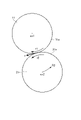
- FIG. FIG. 4 is a plan view showing the rotating body of the fixed unit and the rotating body of the drive unit according to the embodiment; It is a top view which shows the 1st gearwheel and the 2nd gearwheel of this embodiment.
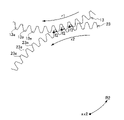
- FIG. 4 is an enlarged plan view showing a first gear and a second gear rotating with rotation of a rotating body
- FIG. 11 is an enlarged plan view showing a state in which the second gear collides with the first gear due to slip occurring between the rotating bodies; It is an enlarged plan view showing how the first gear and the second gear mesh and rotate.
- FIG. 1 is a perspective view showing the overall configuration of a driving force transmission mechanism according to this embodiment.
- FIG. 2 is a plan view showing the overall configuration of the driving force transmission mechanism according to this embodiment.
- FIG. 3 is a plan view showing the rotating body of the fixed unit and the rotating body of the drive unit of this embodiment.
- FIG. 4 is a plan view showing the first gear and the second gear of this embodiment.
- FIG. 5 is an enlarged plan view showing the first gear and the second gear rotating with the rotation of the rotating body.
- FIG. 6 is an enlarged plan view showing how the second gear collides with the first gear due to the occurrence of a slip between the rotating bodies.
- FIG. 7 is an enlarged plan view showing how the first gear and the second gear mesh and rotate.
- the gap (also called backlash) between the tooth portion 13a of the first gear 13 and the tooth portion 23a of the second gear 23 is shown larger than it actually is.
- the gap between the tooth portion 13a of the first gear 13 and the tooth portion 23a of the second gear 23 may be of a size that allows the gears to mesh with each other and rotate.
- the driving force transmission mechanism 100 is a device that drives the end effector 232 by transmitting a driving force input from a power source such as a motor (not shown).
- the driving force transmission mechanism 100 may be used, for example, in arm or leg joints of a humanoid or animal robot. Further, the driving force transmission mechanism 100 may be housed in a housing that constitutes the exterior of a humanoid or animal robot.
- the configuration of the driving force transmission mechanism 100 will be described below with reference to FIGS. 1 and 2.
- FIG. The driving force transmission mechanism 100 has a fixed unit 10 , a drive unit 20 and a link mechanism 30 .
- the fixing unit 10 includes an adapter 131 and is used by connecting the adapter 131 to a member other than the driving force transmission mechanism 100 for fixing.
- the adapter 131 may be connected to, for example, a torso portion of a humanoid or animal robot.
- the fixed unit 10 includes a rotating body 11, a rotating body 12, and a gear 13, as shown in FIG.
- the gear 13 is provided sandwiched between the rotor 11 and the rotor 12 in the direction in which the rotation axis ax1 extends.
- the rotating body 11, the rotating body 12, and the gear 13 are fixed to each other so as to rotate integrally around the rotation axis ax1.
- the rotator 11 and the rotator 12 are disk-shaped with the same diameter length. Further, the rotating body 11 is made of a member having elasticity at least on the outer peripheral surface 11a. The rotating body 12 is also the same.
- a shaft hole through which the input support portion 31 of the link mechanism 30 is inserted is formed in the central portion of the fixed unit 10 . That is, shaft holes penetrating in the direction in which the rotation axis ax1 extends are formed in the central portions of the rotating body 11, the rotating body 12, and the gear 13, respectively.
- the gear 13 is partially formed with a plurality of tooth portions 13a corresponding to the movable range in the circumferential direction of the rotation axis ax1, and tooth portions are formed in other portions in the circumferential direction. not formed.
- the adapter 131 described above is provided in a portion of the gear 13 where the toothed portion 13a is not formed. 5 to 7, only some of the plurality of teeth 13a are denoted by reference numerals, and the adapter 131 is omitted in FIG.
- the drive unit 20 includes a rotating body 21, a rotating body 22, and a gear 23, as shown in FIG.
- the gear 23 is provided sandwiched between the rotating body 21 and the rotating body 22 in the direction in which the rotation axis ax2 extends.
- the rotor 21, the rotor 22, and the gear 23 are fixed to each other so as to rotate integrally about the rotation axis ax2.
- the rotator 21 and the rotator 22 are disk-shaped with the same diameter length. Further, the rotating body 21 is made of a member having elasticity at least at the outer peripheral surface 21a. The rotating body 22 is also the same.
- the rotating body 21 is provided in pressure contact with the rotating body 11 .
- the rotating body 22 is provided in pressure contact with the rotating body 12 .
- a shaft hole through which the output support portion 32 of the link mechanism 30 is inserted is formed in the central portion of the drive unit 20 . That is, shaft holes penetrating in the direction in which the rotation axis ax2 extends are formed in the central portions of the rotating body 21, the rotating body 22, and the gear 23, respectively.
- the gear 23 is partially formed with a plurality of teeth 23a corresponding to the movable range in the circumferential direction of the rotation axis ax2, and no teeth are formed in other portions in the circumferential direction.
- the adapter 231 described above is provided in a portion of the gear 23 where the toothed portion 23a is not formed.
- An end effector 232 is attached to the adapter 231 . 1 and 2 show, as an example, the end effector 232 having a shape in which a sphere is provided at the rod-like tip, but the end effector 232 is not limited to this.
- the end effector 232 may be, for example, hand-shaped or foot-shaped. 5 to 7, only some of the plurality of teeth 23a are denoted by reference numerals, and the illustration of the adapter 231 is omitted in FIG.
- the link mechanism 30 includes an input support portion (first support portion) 31, an output support portion (second support portion) 32, and a connection portion 33 that connects the input support portion 31 and the output support portion 32. .
- a rotational force from a drive source such as a motor (not shown) is input to the input support portion 31 .
- the input support portion 31 is inserted through the shaft hole of the fixed unit 10 and supports the fixed unit 10 .
- the output support portion 32 is inserted through the shaft hole of the drive unit 20 and supports the drive unit 20 .
- the link mechanism 30 includes, as the connecting portion 33, a connecting portion 33A and a connecting portion 33B.
- the connection portion 33A extends along a line connecting the rotation axis ax1 and the rotation axis ax2, and extends between one end of the input support portion 31 in the direction in which the rotation axis ax1 extends and the output support portion 32 in the direction in which the rotation axis ax2 extends. connected to one end.
- connection portion 33B extends along a line connecting the rotation axis ax1 and the rotation axis ax2, and is connected to the other end side of the input support portion 31 in the direction in which the rotation axis ax1 extends and the output support portion 32 in the direction in which the rotation axis ax2 extends. is connected to the other end of the That is, the fixed unit 10 and the drive unit 20 are provided so as to be sandwiched between the connection portion 33A and the connection portion 33B in the direction in which the rotation axis ax1 (the rotation axis ax2) extends.
- a driving force (rotational force) is input to the input support portion 31 of the link mechanism 30 from a power source such as a motor.
- a power source such as a motor.
- the input support portion 31 rotates in the R1 direction shown in FIG. 2 around the rotation axis ax1.
- the output support portion 32 integrated with the input support portion 31 rotates in the R2 direction shown in FIG. 2 around the rotation axis ax1.
- the drive unit 20 As the output support portion 32 rotates in the R2 direction shown in FIG. 2 around the rotation axis ax1, the drive unit 20 also rotates in the R2 direction. That is, the drive unit 20 rotates along the outer shape of the fixed unit 10 around the rotation axis ax1. In other words, the drive unit 20 moves relative to the fixed unit 10 in the circumferential direction of the rotation axis ax ⁇ b>1 along the outer peripheral surfaces of the rotating bodies 11 and 12 .
- a frictional force (kinetic frictional force) F is generated between the rotor 11 and the rotor 21 which are in pressure contact with each other.
- a frictional force (dynamic frictional force) F is also generated between the rotating bodies 12 and 22 in the same manner. Due to this frictional force F, the rotating bodies 21 and 22 rotate about the rotation axis ax2 in the r2 direction shown in FIGS. It rotates in the r1 direction shown in FIGS.
- the magnitude of the frictional force F is preferably adjusted by, for example, the surface roughness of the outer peripheral surface of the rotating body.
- the gear 13 integrally formed with the rotating bodies 11 and 12 also rotates in the r1 direction around the rotation axis ax1.
- the gear 23 integrally formed with the rotating bodies 21 and 22 also rotates in the r2 direction shown in FIG. 2 around the rotation axis ax2. That is, the fixed unit 10 rotates in the r1 direction, and the driving unit 20 rotates in the r2 direction.
- the frictional force F generated between the rotating bodies 11 and 21 and between the rotating bodies 12 and 22 rotates the fixed unit 10 in the r1 direction
- the gears 13 and 23 rotate while maintaining non-contact with each other.
- FIG. 5 shows how the gear 13 rotates in the r1 direction while maintaining a non-contact state with the gear 23, and the gear 23 rotates in the r2 direction while maintaining a non-contact state with the gear 13. ing.
- the drive unit 20 can be moved relative to the fixed unit 10 in the circumferential direction of the rotation axis ax1 and rotated around the rotation axis ax2. can. Thereby, the end effector 232 can be driven.
- the explanation is omitted, when the input support portion 31 is rotated in the direction opposite to the direction R1 shown in FIG. That is, the drive unit 20 rotates about the rotation axis ax1 along the outer shape of the fixed unit 10 in the direction opposite to the R2 direction shown in FIG. It will rotate in the direction opposite to the indicated R3 direction.
- an external force greater than the frictional force F generated between the rotating bodies 11 and 21 and between the rotating bodies 12 and 22 (hereinafter also simply referred to as “between the rotating bodies”) is applied to the rotating bodies. If it works between them, the rotating body 21 may slip on the rotating body 11 .
- the slip means slippage of the outer peripheral surface 21a of the rotating body 21 with respect to the outer peripheral surface 11a of the rotating body 11. It means that the positional relationship in the circumferential direction is displaced.
- the rotating body 21 slips with respect to the rotating body 11
- the rotating body 22 also slips with respect to the rotating body 12 .
- the fixed unit 10 includes the gear 13 in addition to the rotating bodies 11 and 12
- the drive unit 20 includes the gear 23 in addition to the rotating bodies 21 and 22. configuration is adopted.
- FIG. 6 shows the gear 13 and the gear 23 when slip occurs between the rotating bodies.
- the dashed lines shown in FIG. 6 indicate the gear 13 and the gear 23 when no slip occurs between the rotating bodies. That is, the dashed line shown in FIG. 6 indicates the positional relationship between the gears 13 and 23 when no slip occurs between the rotating bodies.
- FIG. 6 shows how the gear 23 collides with the gear 13 as the drive unit 20 rotates in the direction of the arrow R2 so as to follow the outer shape of the fixed unit 10 around the rotation axis ax1.
- a pressing force f1 is applied to the gear 13 in the direction indicated by the arrow in FIG. More specifically, in FIG. 6, with respect to the downstream side surface of the tooth portion 13a of the gear 13 in the r1 direction (see FIG. 6), the side surface of the tooth portion 23a of the gear 23 on the upstream side in the r2 direction shows how they collided.
- FIG. 7 shows how the gear 23 receives the reaction force f2 from the gear 13 and rotates about the rotation axis ax2 in the r2 direction.
- the fixed unit 10 rotates about the rotation axis ax1 in the r1 direction, and the drive unit 20 rotates about the rotation axis ax2.
- the drive unit 20 rotates about the rotation axis ax2.
- the driving force transmission mechanism 100 when no external force acts between the rotating bodies, the driving force is transmitted by the rotation of the rotating bodies. , the gears mesh with each other to transmit the driving force. Therefore, when no external force is acting between the rotating bodies, there is no collision sound of gears, etc., and quietness is maintained. In addition, compared to the case where gears are meshed to rotate, the end effector 232 can be driven at a desired timing because there is no loss due to backlash. On the other hand, when an external force acts between the rotating bodies, the driving force can be transmitted by meshing the gears. Thus, the driving force transmission mechanism 100 can be used in an environment where driving force is transmitted without loss and quietness is required.
- the diameter of the fixed unit 10 and the diameter of the drive unit 20 are the same is shown, but these diameters may be different from each other.
- the speed of rotation of the drive unit 20 about the rotation axis ax2 can be reduced or increased.
- the outer peripheral surfaces of the rotating body 11 and the rotating body 21 both have elasticity and are elastically pressed against each other. It is sufficient that a frictional force is generated between the body 11 and the rotating body 21 .
- the outer peripheral surface of one of the rotating bodies 11 and 21 may have elasticity, and the outer peripheral surface of the other may be rigid. The same applies to the outer peripheral surfaces of the rotating bodies 12 and 22 that are in pressure contact with each other.
- each rotating body is a disk-shaped member
- it is not limited to this as long as it has an outer peripheral surface that presses against each other.
- belts having their outer peripheral surfaces in pressure contact with each other may be used as the rotating bodies.
- the fixed unit 10 includes two rotating bodies sandwiching the gear 13 and the drive unit 20 includes two rotating bodies sandwiching the gear 23 . Since the rotor of the fixed unit 10 and the rotor of the drive unit 20 are elastically pressed against each other, a reaction force is generated between the rotors. In this embodiment, since it has a symmetrical configuration in the direction in which the rotation axis ax1 (rotation axis ax2) extends, the reaction force acting between the rotating bodies 11 and 21 and the rotating bodies 12 and 22 The reaction force acting between them cancels each other out, and the postures of the fixed unit 10 and the drive unit 20 are stabilized.
- the fixed unit 10 may include only one rotating body. That is, the fixed unit 10 may have the rotating body 11 and the gear 13 and not have the rotating body 12 . In this case, the drive unit 20 may have the rotor 21 and the gear 23 and not the rotor 22 .
- the thickness of the gear 13 in the direction of the rotation axis ax1 is preferably smaller than the thickness of the rotating body 11.
- the thickness of gear 23 in the direction of rotation axis ax2 is preferably smaller than the thickness of rotating body 21 .
- the link mechanism 30 rotates around the rotation axis ax1, thereby rotating the drive unit 20 along the outer shape of the fixed unit 10.
- the configuration is not limited to this. . That is, the configuration may be such that the drive unit 20 does not move relative to the fixed unit 10 . In this case, the fixed unit 10 and the drive unit 20 maintain their relative positions, and the end effector 232 is driven by the drive unit 20 rotating about the rotation axis ax2.
Landscapes
- Engineering & Computer Science (AREA)
- General Engineering & Computer Science (AREA)
- Mechanical Engineering (AREA)
- Robotics (AREA)
- Manipulator (AREA)
- Friction Gearing (AREA)
- Gear Transmission (AREA)
- Transmission Devices (AREA)
Abstract
Description
駆動力伝達機構100は、不図示のモータ等の動力源から入力される駆動力を伝達することでエンドエフェクタ232を駆動する装置である。駆動力伝達機構100は、例えば、人型又は動物型のロボットの腕や脚の関節に用いられるとよい。また、駆動力伝達機構100は、人型又は動物型のロボットの外装を構成するハウジング内に収容して用いられるとよい。
以下、図1、図2を参照して、駆動力伝達機構100の構成について説明する。駆動力伝達機構100は、固定ユニット10と、駆動ユニット20と、リンク機構30とを有している。
固定ユニット10は、アダプタ131を含み、アダプタ131が駆動力伝達機構100以外の他の部材に固定するよう接続して用いられる。アダプタ131は、例えば、人型又は動物型のロボットの胴体部分に接続されているとよい。
駆動ユニット20は、図1に示すように、回転体21と、回転体22と、歯車23とを含んでいる。歯車23は、回転軸ax2が延びる方向において、回転体21と回転体22に挟まれて設けられている。回転体21、回転体22、及び歯車23は、回転軸ax2を回転中心として一体に回転するように、互いに固定されている。
リンク機構30は、入力支持部(第1支持部)31と、出力支持部(第2支持部)32と、入力支持部31と出力支持部32とを接続する接続部33とを含んでいる。
次に、駆動力伝達機構100の動作について説明する。
Claims (8)
- 第1外周面を有し、第1回転軸を回転中心として回転する第1回転体と、
前記第1外周面に圧接される第2外周面を有し、前記第1外周面との間に生じる摩擦力により、第2回転軸を回転中心として回転する第2回転体と、
前記第1回転軸を回転中心として、前記第1回転体と一体に回転する第1歯車と、
前記第2回転軸を回転中心として、前記第2回転体と一体に回転する第2歯車と、
を有し、
前記第1歯車と前記第2歯車は、前記第2外周面が前記第1外周面に対してスリップした場合に、互いに噛み合うように設けられている、
駆動力伝達機構。 - 第3外周面を有し、前記第1回転軸が延びる方向において前記第1回転体と共に前記第1歯車を挟み、前記第1回転軸を回転中心として前記第1回転体及び前記第1歯車と一体に回転する第3回転体と、
前記第3外周面に圧接される第4外周面を有し、前記第2回転軸が延びる方向において前記第2回転体と共に前記第2歯車を挟むと共に、前記第2外周面との間に生じる摩擦力により、前記第2回転軸を回転中心として前記第2回転体及び前記第2歯車と一体に回転する第4回転体と、
を有する、
請求項1に記載の駆動力伝達機構。 - 前記第1回転軸を回転中心として前記第1回転体及び前記第1歯車を回転可能に支持する第1支持部と、
前記第2回転軸を回転中心として前記第2回転体及び前記第2歯車を回転可能に支持する第2支持部と、
前記第1回転軸と前記第2回転軸とを繋ぐ線に沿って延びており、前記第1支持部と前記第2支持部とを接続する接続部と、
を有する、
請求項1又は2に記載の駆動力伝達機構。 - 前記第1支持部は、動力源からの駆動力により前記第1回転軸を回転中心として回転可能に設けられており、
前記第2支持部は、前記第1回転軸を回転中心とする前記第1支持部の回転に伴って、前記第1回転軸を回転中心として前記第1外周面に沿うように前記第2回転体を回転させる、
請求項3に記載の駆動力伝達機構。 - 前記第1歯車と前記第2歯車は、前記第1回転体が前記第1回転軸を回転中心として回転すると共に前記第2回転体が前記第2回転軸を回転中心として回転する際に、互いに非接触状態を維持して回転可能に設けられている、
請求項1~4のいずれか1項に記載の駆動力伝達機構。 - 前記第1回転軸が延びる方向における前記第1歯車の厚みは前記第1回転体よりも小さい、
請求項1~5のいずれか1項に記載の駆動力伝達機構。 - 前記第1外周面及び前記第2外周面の少なくとも一方は、弾性を有しており、他方に対して弾性的に圧接されている、
請求項1~6のいずれか1項に記載の駆動力伝達機構。 - 前記第1歯車は、前記第1回転軸の周方向における可動範囲に応じた歯部が部分的に形成されている、
請求項1~7のいずれか1項に記載の駆動力伝達機構。
Priority Applications (2)
| Application Number | Priority Date | Filing Date | Title |
|---|---|---|---|
| US18/550,169 US12313151B2 (en) | 2021-03-30 | 2022-03-17 | Drive power transmitting mechanism |
| JP2023510953A JP7502556B2 (ja) | 2021-03-30 | 2022-03-17 | 駆動力伝達機構 |
Applications Claiming Priority (2)
| Application Number | Priority Date | Filing Date | Title |
|---|---|---|---|
| JP2021-057987 | 2021-03-30 | ||
| JP2021057987 | 2021-03-30 |
Publications (1)
| Publication Number | Publication Date |
|---|---|
| WO2022209983A1 true WO2022209983A1 (ja) | 2022-10-06 |
Family
ID=83456150
Family Applications (1)
| Application Number | Title | Priority Date | Filing Date |
|---|---|---|---|
| PCT/JP2022/012414 Ceased WO2022209983A1 (ja) | 2021-03-30 | 2022-03-17 | 駆動力伝達機構 |
Country Status (3)
| Country | Link |
|---|---|
| US (1) | US12313151B2 (ja) |
| JP (1) | JP7502556B2 (ja) |
| WO (1) | WO2022209983A1 (ja) |
Citations (3)
| Publication number | Priority date | Publication date | Assignee | Title |
|---|---|---|---|---|
| JP2002213566A (ja) * | 2001-01-15 | 2002-07-31 | Sumitomo Heavy Ind Ltd | パラレル駆動の変速機 |
| JP2006064170A (ja) * | 2004-02-03 | 2006-03-09 | Nissan Motor Co Ltd | 変速装置およびそれを用いた車両用可変舵角装置 |
| JP2006300221A (ja) * | 2005-04-21 | 2006-11-02 | Mitsubishi Heavy Ind Ltd | 遊星ローラ駆動装置及び同装置を設置したステアリング装置 |
Family Cites Families (2)
| Publication number | Priority date | Publication date | Assignee | Title |
|---|---|---|---|---|
| JP2003269579A (ja) | 2002-03-18 | 2003-09-25 | Sony Corp | 動力伝達装置及びロボット装置 |
| JP2008094381A (ja) * | 2006-09-14 | 2008-04-24 | Jtekt Corp | 減速歯車機構及び電動パワーステアリング装置 |
-
2022
- 2022-03-17 JP JP2023510953A patent/JP7502556B2/ja active Active
- 2022-03-17 WO PCT/JP2022/012414 patent/WO2022209983A1/ja not_active Ceased
- 2022-03-17 US US18/550,169 patent/US12313151B2/en active Active
Patent Citations (3)
| Publication number | Priority date | Publication date | Assignee | Title |
|---|---|---|---|---|
| JP2002213566A (ja) * | 2001-01-15 | 2002-07-31 | Sumitomo Heavy Ind Ltd | パラレル駆動の変速機 |
| JP2006064170A (ja) * | 2004-02-03 | 2006-03-09 | Nissan Motor Co Ltd | 変速装置およびそれを用いた車両用可変舵角装置 |
| JP2006300221A (ja) * | 2005-04-21 | 2006-11-02 | Mitsubishi Heavy Ind Ltd | 遊星ローラ駆動装置及び同装置を設置したステアリング装置 |
Also Published As
| Publication number | Publication date |
|---|---|
| US20240151297A1 (en) | 2024-05-09 |
| JP7502556B2 (ja) | 2024-06-18 |
| JPWO2022209983A1 (ja) | 2022-10-06 |
| US12313151B2 (en) | 2025-05-27 |
Similar Documents
| Publication | Publication Date | Title |
|---|---|---|
| JP5338223B2 (ja) | スカラロボットの手首軸回転駆動機構 | |
| EP2759743B1 (en) | Speed reducer | |
| TWI675976B (zh) | 齒輪變速器 | |
| TW200532124A (en) | Eccentrically swinging gear device | |
| JP2010151269A (ja) | 回転駆動装置、ロボットの関節構造及びロボットアーム | |
| KR20100008580U (ko) | 감속기 | |
| TW202016450A (zh) | 撓曲嚙合式齒輪裝置 | |
| JPWO2017110840A1 (ja) | 遊星歯車機構を組み合わせた回転伝達装置 | |
| JP6554578B2 (ja) | サイクロ減速機 | |
| JP2025078819A (ja) | 減速機、及び、回転装置 | |
| JP4737695B2 (ja) | 指関節機構 | |
| JP2012066323A (ja) | 操作機構 | |
| CN213981742U (zh) | 旋转限制机构、旋转致动器和机器人 | |
| KR101007069B1 (ko) | 2단 유성기어시스템을 구비한 기어박스 | |
| CN114667402B (zh) | 离合器装置以及马达单元 | |
| JPWO2017217415A1 (ja) | 関節ユニット | |
| JP7502556B2 (ja) | 駆動力伝達機構 | |
| WO2018123895A1 (ja) | 減速装置、関節装置及びロボットアーム構造 | |
| JP2008094381A (ja) | 減速歯車機構及び電動パワーステアリング装置 | |
| KR101301702B1 (ko) | 마찰구동을 이용한 감속장치 | |
| JP2020203363A5 (ja) | ||
| TW201217124A (en) | Robot arm assembly | |
| JP2009074611A (ja) | 回転駆動装置、ロボットの関節構造及びロボットアーム | |
| JP2018194056A (ja) | リンク作動装置 | |
| WO2025028290A1 (ja) | 揺動型歯車機構、減速機及びロボットアーム |
Legal Events
| Date | Code | Title | Description |
|---|---|---|---|
| 121 | Ep: the epo has been informed by wipo that ep was designated in this application |
Ref document number: 22780202 Country of ref document: EP Kind code of ref document: A1 |
|
| WWE | Wipo information: entry into national phase |
Ref document number: 2023510953 Country of ref document: JP |
|
| WWE | Wipo information: entry into national phase |
Ref document number: 18550169 Country of ref document: US |
|
| NENP | Non-entry into the national phase |
Ref country code: DE |
|
| 122 | Ep: pct application non-entry in european phase |
Ref document number: 22780202 Country of ref document: EP Kind code of ref document: A1 |
|
| WWG | Wipo information: grant in national office |
Ref document number: 18550169 Country of ref document: US |