WO2022209752A1 - 多孔質熱可塑性樹脂の製造方法 - Google Patents
多孔質熱可塑性樹脂の製造方法 Download PDFInfo
- Publication number
- WO2022209752A1 WO2022209752A1 PCT/JP2022/010868 JP2022010868W WO2022209752A1 WO 2022209752 A1 WO2022209752 A1 WO 2022209752A1 JP 2022010868 W JP2022010868 W JP 2022010868W WO 2022209752 A1 WO2022209752 A1 WO 2022209752A1
- Authority
- WO
- WIPO (PCT)
- Prior art keywords
- thermoplastic resin
- porous thermoplastic
- porous
- resin sheet
- sheet
- Prior art date
- Legal status (The legal status is an assumption and is not a legal conclusion. Google has not performed a legal analysis and makes no representation as to the accuracy of the status listed.)
- Ceased
Links
Images

Classifications
-
- B—PERFORMING OPERATIONS; TRANSPORTING
- B29—WORKING OF PLASTICS; WORKING OF SUBSTANCES IN A PLASTIC STATE IN GENERAL
- B29C—SHAPING OR JOINING OF PLASTICS; SHAPING OF MATERIAL IN A PLASTIC STATE, NOT OTHERWISE PROVIDED FOR; AFTER-TREATMENT OF THE SHAPED PRODUCTS, e.g. REPAIRING
- B29C44/00—Shaping by internal pressure generated in the material, e.g. swelling or foaming ; Producing porous or cellular expanded plastics articles
-
- C—CHEMISTRY; METALLURGY
- C08—ORGANIC MACROMOLECULAR COMPOUNDS; THEIR PREPARATION OR CHEMICAL WORKING-UP; COMPOSITIONS BASED THEREON
- C08J—WORKING-UP; GENERAL PROCESSES OF COMPOUNDING; AFTER-TREATMENT NOT COVERED BY SUBCLASSES C08B, C08C, C08F, C08G or C08H
- C08J5/00—Manufacture of articles or shaped materials containing macromolecular substances
- C08J5/18—Manufacture of films or sheets
-
- C—CHEMISTRY; METALLURGY
- C08—ORGANIC MACROMOLECULAR COMPOUNDS; THEIR PREPARATION OR CHEMICAL WORKING-UP; COMPOSITIONS BASED THEREON
- C08J—WORKING-UP; GENERAL PROCESSES OF COMPOUNDING; AFTER-TREATMENT NOT COVERED BY SUBCLASSES C08B, C08C, C08F, C08G or C08H
- C08J9/00—Working-up of macromolecular substances to porous or cellular articles or materials; After-treatment thereof
- C08J9/04—Working-up of macromolecular substances to porous or cellular articles or materials; After-treatment thereof using blowing gases generated by a previously added blowing agent
-
- C—CHEMISTRY; METALLURGY
- C08—ORGANIC MACROMOLECULAR COMPOUNDS; THEIR PREPARATION OR CHEMICAL WORKING-UP; COMPOSITIONS BASED THEREON
- C08J—WORKING-UP; GENERAL PROCESSES OF COMPOUNDING; AFTER-TREATMENT NOT COVERED BY SUBCLASSES C08B, C08C, C08F, C08G or C08H
- C08J9/00—Working-up of macromolecular substances to porous or cellular articles or materials; After-treatment thereof
- C08J9/04—Working-up of macromolecular substances to porous or cellular articles or materials; After-treatment thereof using blowing gases generated by a previously added blowing agent
- C08J9/12—Working-up of macromolecular substances to porous or cellular articles or materials; After-treatment thereof using blowing gases generated by a previously added blowing agent by a physical blowing agent
-
- C—CHEMISTRY; METALLURGY
- C08—ORGANIC MACROMOLECULAR COMPOUNDS; THEIR PREPARATION OR CHEMICAL WORKING-UP; COMPOSITIONS BASED THEREON
- C08J—WORKING-UP; GENERAL PROCESSES OF COMPOUNDING; AFTER-TREATMENT NOT COVERED BY SUBCLASSES C08B, C08C, C08F, C08G or C08H
- C08J9/00—Working-up of macromolecular substances to porous or cellular articles or materials; After-treatment thereof
- C08J9/26—Working-up of macromolecular substances to porous or cellular articles or materials; After-treatment thereof by elimination of a solid phase from a macromolecular composition or article, e.g. leaching out
-
- Y—GENERAL TAGGING OF NEW TECHNOLOGICAL DEVELOPMENTS; GENERAL TAGGING OF CROSS-SECTIONAL TECHNOLOGIES SPANNING OVER SEVERAL SECTIONS OF THE IPC; TECHNICAL SUBJECTS COVERED BY FORMER USPC CROSS-REFERENCE ART COLLECTIONS [XRACs] AND DIGESTS
- Y02—TECHNOLOGIES OR APPLICATIONS FOR MITIGATION OR ADAPTATION AGAINST CLIMATE CHANGE
- Y02P—CLIMATE CHANGE MITIGATION TECHNOLOGIES IN THE PRODUCTION OR PROCESSING OF GOODS
- Y02P20/00—Technologies relating to chemical industry
- Y02P20/50—Improvements relating to the production of bulk chemicals
- Y02P20/54—Improvements relating to the production of bulk chemicals using solvents, e.g. supercritical solvents or ionic liquids
Definitions
- the present invention relates to a method for producing a porous thermoplastic resin.
- a method for producing a porous thermoplastic resin in which a porosifying agent is extracted from a composition containing a thermoplastic resin and a porosifying agent by a supercritical extraction method using supercritical carbon dioxide as an extraction solvent (for example, , See Patent Document 1 below.).
- the present invention provides a method for producing a porous thermoplastic resin that is excellent in performance, low in cost, and capable of producing a porous thermoplastic resin having a high porosity.
- the present invention (1) comprises a first step of kneading a thermoplastic resin and a porosifying agent to prepare a composition containing the thermoplastic resin and the porosifying agent; a second step of extracting the porosity agent with the supercritical fluid to form a porous thermoplastic resin while impregnating the article; and a third step of foaming the porous thermoplastic resin by dropping the supercritical fluid below the critical point.
- the porosity agent is extracted to form the porous thermoplastic resin, and in the third step, the porous thermoplastic resin is further foamed. Porous thermoplastic resins with porosity can be produced.
- the porous thermoplastic resin is further foamed in the third step. Therefore, a porous thermoplastic resin having a sufficiently high porosity can be produced. Therefore, it is possible to suppress deterioration in the performance of the porous thermoplastic resin due to the high blending ratio of the porosifying agent, and to reduce the production cost.
- the ratio V of the volume of the porosifying agent to the total volume of the thermoplastic resin and the porosifying agent in the first step The method for producing a porous thermoplastic resin according to (1), wherein the third step is performed such that the porosity P ratio (P/V) exceeds 1.0.
- the porous thermoplastic resin is foamed so that the ratio (P/V) exceeds 1 in the third step.
- foaming of the porous thermoplastic resin based on separation of the supercritical fluid impregnated in the porous thermoplastic resin from the porous thermoplastic resin can be reliably carried out.
- the present invention (3) includes the method for producing a porous thermoplastic resin according to (1) or (2), wherein the thermoplastic resin is a liquid crystal polymer.
- thermoplastic resin is a liquid crystal polymer
- a porous thermoplastic resin having a low dielectric constant and a low dielectric loss tangent can be produced.
- a nonporous sheet made of the composition is prepared, and in the second step, a porous thermoplastic resin sheet made of a porous thermoplastic resin is formed, ( It includes the method for producing a porous thermoplastic resin according to 1) or (2).
- a thin porous thermoplastic resin sheet having a low dielectric constant and a low dielectric loss tangent can be produced.
- thermoplastic resin having excellent performance, low cost, and high porosity.
- FIG. 1A to 1C are process diagrams of a method for producing a porous thermoplastic resin sheet, which is one embodiment of the method for producing a porous thermoplastic resin of the present invention.
- FIG. 1A is the first step.
- FIG. 1B is the second step.
- FIG. 1C is the third step.
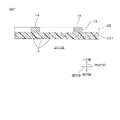
- FIG. 2 is a cross-sectional view of a wired circuit board provided with a porous thermoplastic resin sheet.
- a method for producing a porous thermoplastic resin sheet 1, which is one embodiment of the method for producing a porous thermoplastic resin of the present invention, will be described with reference to FIGS. 1A to 1C.
- This manufacturing method includes a first step, a second step, and a third step. In this manufacturing method, for example, the first to third steps are performed in order.
- thermoplastic resin and a porosity agent are kneaded. Thereby, a composition containing the thermoplastic resin and the porosity agent is prepared.
- thermoplastic resin is not limited.
- thermoplastic resins include liquid crystal polymers, olefin resins, acrylic resins, polystyrene resins, polyester resins, polyacrylonitrile resins, maleimide resins, polyvinyl acetate resins, ethylene-vinyl acetate copolymers, polyvinyl alcohol resins, polyamide resins, Polyvinyl chloride resin, polyacetal resin, polyphenylene oxide resin, polyphenylene sulfide resin, polysulfone resin, polyethersulfone resin, polyetheretherketone resin, polyarylsulfone resin, thermoplastic polyimide resin, thermoplastic polyimide fluoride resin, thermoplastic urethane Resins, polyetherimide resins, polymethylpentene resins, cellulose resins, and ionomers.
- a liquid crystal polymer is preferred from the viewpoint of producing a porous thermoplastic resin sheet 1 having a low dielectric constant and a low dielectric
- the liquid crystal polymer is not limited.
- a liquid crystal polymer is a liquid crystalline thermoplastic resin.
- liquid crystalline polymers include liquid crystalline polyesters, preferably aromatic liquid crystalline polyesters.
- Liquid crystal polymers are specifically described, for example, in JP-A-2020-147670 and JP-A-2004-189867.
- a commercial item can be used for the liquid crystal polymer.
- Commercially available products include, for example, UENO LCP (registered trademark, hereinafter the same) 8100 series (low melting point type, manufactured by Ueno Pharmaceutical Co., Ltd.) and UENO LCP 5000 series (high melting point type, manufactured by Ueno Pharmaceutical Co., Ltd.).
- UENO LCP8100 series is mentioned.
- the melting point of the thermoplastic resin is not limited.
- the melting point of the thermoplastic resin is, for example, 100° C. or higher, preferably 200° C. or higher, more preferably 220° C. or higher, and for example, 400° C. or lower, preferably 370° C. or lower.
- the melting point of thermoplastic resins is determined by differential scanning calorimetry. In differential scanning calorimetry, the heating rate is 10° C./min, the range from 25° C. to 400° C. is scanned, and the thermoplastic resin is heated in a nitrogen atmosphere. Moreover, if the thermoplastic resin is a commercial product, the catalog value of the commercial product can be adopted as it is.
- the porous thermoplastic resin sheet 1 will be excellent in handleability and workability. If the melting point of the thermoplastic resin is equal to or higher than the above lower limit, the porous thermoplastic resin sheet 1 will be excellent in heat resistance.
- the glass transition temperature of the thermoplastic resin is not limited.
- the glass transition temperature of the thermoplastic resin is, for example, 80° C. or higher and, for example, 125° C. or lower.
- the glass transition temperature of a thermoplastic resin is determined by differential scanning calorimetry performed at a heating rate of 10°C/min.
- a porosity agent is a component dispersed in a thermoplastic resin to make the thermoplastic resin porous.
- the porosity agent is a component for forming first pores 26 (described later, FIG. 1B) in the nonporous sheet 3 .
- the porosity agent undergoes phase separation from the thermoplastic resin, for example, at a kneading temperature (described later). Phase separation involves ensuring a consistent shape in the kneaded material without dissolving in the thermoplastic resin.
- porosity agent is not limited.
- porosity agents include, for example, silicone compounds and polyalkylene glycol compounds (specifically, polyoxyethylene dimethyl ether).
- Porosifying agents also include, for example, purine compounds, bisphenol AF compounds, pearl fluoropolyether compounds, calixarene compounds, acene compounds, and dicarboxylic acid anhydrides. These can be used alone or in combination.
- a silicone compound is preferably used from the viewpoint of ensuring phase separation from the thermoplastic resin in the first step.
- the porosity agent preferably, from the viewpoint of reliably performing the first step and reliably forming the first pores 26 in the second step, a purine compound, a bisphenol AF compound, a pearl fluoropolyether compound, and at least one selected from the group consisting of calixarene compounds.
- silicone compounds include straight silicone oils.
- Straight silicone oils include, for example, dimethyl silicone oil, methylphenyl silicone oil, and diphenyl silicone oil.
- Straight silicone oil preferably includes methylphenyl silicone oil.
- Purine compounds include, for example, caffeine, theobromine, and theophylline-7-acetic acid, and from the viewpoint of obtaining high extraction efficiency and high porosity, caffeine and theobromine are included.
- Bisphenol AF compounds include, for example, 2,2′-diphenyl[5,5′-bi-1H-isoindole]-1,1′,3,3′(2H,2H′)-tetrone, and 2, 2-bis(4-carboxyphenyl)hexafluoropropane can be mentioned.
- Perfluoropolyether compounds include, for example, perfluoropolyethers. The weight average molecular weight (catalog value) of perfluoropolyether is, for example, 1000 or more and 10,000 or less.
- calixarene compounds examples include p-tert-butylcalix[4]arene.
- Acene compounds include, for example, pentacenedione.
- dicarboxylic anhydrides examples include 4,4'-oxydiphthalic anhydride.
- the mass reduction rate of the porosity agent at 230°C is, for example, 20% by mass or less, preferably 10% or less, more preferably 5% or less, and even more preferably 3% or less.
- 230°C is a temperature included in the kneading temperature described later.
- the mass reduction rate of the porosifying agent at 230°C is equal to or less than the upper limit described above, it is possible to suppress excessive thermal decomposition in the kneading in the first step. can be made porous.
- the lower limit of the mass reduction rate of the porosity agent at 230°C is not limited.
- the lower limit of the mass reduction rate of the porosity agent at 230°C is, for example, 0%, and further 1%.
- the mass reduction rate of the porosity agent at 230°C is measured as the mass (weight) reduction rate at 230°C in thermogravimetric analysis at a heating rate of 10°C/min and a scanning temperature of 40°C to 400°C. The details of the measurement method will be described in Examples below.
- the blending ratio of the porosity agent is not limited.
- the volume percentage V of the porosity agent to the total volume of the thermoplastic resin and the porosity agent is, for example, 20% by volume or more, preferably 30% by volume or more, and for example, 90% by volume or less, preferably , 70% by volume or less, more preferably 50% by volume or less, even more preferably 45% by volume or less, and particularly preferably 40% by volume or less.
- the volume percentage V of the porosity agent relative to the total volume of the thermoplastic resin and the porosity agent is obtained by conversion using specific gravity from the percentage of the mass of the porosity agent relative to the total mass of the thermoplastic resin and porosity agent. be done.
- the mass ratio of the porosity agent to 100 parts by mass of the thermoplastic resin is, for example, 10 parts by mass or more, preferably 50 parts by mass or more, and is, for example, 500 parts by mass or less, preferably 250 parts by mass or less. But also.
- Additives can be further kneaded in the first step.
- additives include fillers.
- Fillers include, for example, hollow spheres.
- Hollow spheres include, for example, glass balloons. Hollow spheres are described, for example, in JP-A-2004-189867.
- the additives are not kneaded. If the additive is not kneaded with the thermoplastic resin, the porous thermoplastic resin sheet 1 can be prevented from becoming brittle.
- the kneading temperature is not limited.
- the kneading temperature is set to a temperature at which the amount of thermal decomposition of the porosity agent is small.
- the kneading temperature is, for example, 200° C. or higher, preferably 210° C. or higher, and is, for example, 300° C. or lower, preferably 270° C. or lower, more preferably 250° C. or lower.
- the kneading temperature is, for example, within the range of 230°C ⁇ 30°C (that is, 200°C or higher and 260°C or lower), preferably within the range of 230°C ⁇ 20°C (that is, 210°C or higher and 250°C or lower). , more preferably within the range of 230 ° C. ⁇ 10 ° C. (that is, 220 ° C. or higher and 240 ° C. or lower), still more preferably within the range of 230 ° C. ⁇ 5 ° C. (that is, 225 ° C. or higher and 235 ° C. or lower) .
- the composition is formed into a sheet to prepare a nonporous sheet 3.
- Sheeting the composition includes, for example, pressing, extrusion, and injection. Pressing is preferred, and hot pressing is more preferred.
- the temperature of hot pressing is not limited.
- the temperature of the hot press is set to a temperature at which the amount of thermal decomposition of the porosity agent is small. Specifically, the temperature of the hot press is, for example, 200° C. or higher and 300° C. or lower.
- the press pressure is, for example, 1 MPa or more, preferably 4 MPa or more, and for example, 20 MPa or less, preferably 10 MPa or less.
- the nonporous sheet 3 contains only the thermoplastic resin and the porosity agent. Therefore, the volume percentage V of the porosity agent with respect to the total volume of the thermoplastic resin and the porosity agent is synonymous with the volume percentage V of the porosity agent in the nonporous sheet 3 .
- the thickness of the nonporous sheet 3 is not limited. Specifically, the thickness of the nonporous sheet 3 is, for example, 1000 ⁇ m or less, preferably 500 ⁇ m or less, more preferably 300 ⁇ m or less, still more preferably 200 ⁇ m or less. , 50 ⁇ m or more.
- the porosity agent in the nonporous sheet 3 is extracted with a supercritical fluid.
- the second step uses a supercritical device 10, as shown in FIG. 1B.
- the supercritical device 10 includes a pressure vessel 11 and a circulation device (not shown).
- the pressure vessel 11 accommodates the supercritical fluid 15 and is capable of circulating inside.
- the circulation device circulates the supercritical fluid 15 in the pressure vessel 11 .
- the circulation device is provided with a recovery device.
- a recovery device removes the porosity agent extracted into the supercritical fluid 15 .
- Supercritical Fluid 15 The type of supercritical fluid 15 is not limited. Examples of the supercritical fluid 15 include supercritical carbon dioxide and supercritical nitrogen. Supercritical carbon dioxide (critical temperature: 31° C., critical pressure: 7.4 MPa) is preferably used as the supercritical fluid 15 from the viewpoint of reducing manufacturing costs.
- An entrainer may be blended in the supercritical fluid 15 .
- the entrainer is blended with the supercritical fluid in order to increase the extraction efficiency of the porosity agent by the supercritical fluid.
- the entrainer is compatible with the supercritical fluid 15 and the porosity agent.
- Entrainers include, for example, water, alcohol compounds, ketone compounds, ester compounds, aromatic compounds, and long chain alkyl compounds. These can be used alone or in combination.
- Alcohol compounds include, for example, methanol and ethanol.
- Ketone compounds include, for example, acetone and methyl ethyl ketone.
- Ester compounds include, for example, methyl acetate, ethyl acetate, and propyl acetate.
- Aromatic compounds include, for example, benzene, toluene, and xylene.
- Long chain alkyl compounds include, for example, pentane, hexane, and heptane.
- Entrainers preferably include alcohol compounds and ester compounds.
- the nonporous sheet 3 is placed in the pressure vessel 11. Subsequently, the supercritical fluid 15 is caused to flow into the pressure vessel 11 in the supercritical apparatus 10 . Subsequently, the supercritical fluid 15 is circulated by a circulation device (not shown). These allow the supercritical fluid 15 to contact the nonporous sheet 3 .
- the nonporous sheet 3 is impregnated with the supercritical fluid 15 outside the nonporous sheet 3 . That is, the supercritical fluid 15 penetrates into the nonporous sheet 3 . Then, the supercritical fluid 15 described above returns to the outside of the nonporous sheet 3 while dissolving the porosifying agent. As a result, the porosity agent in the nonporous sheet 3 is extracted with the supercritical fluid 15 .
- part of the supercritical fluid 15 does not return to the outside of the nonporous sheet 3 and stays inside the nonporous sheet 3 .
- the conditions for the second step are not limited.
- the temperature of the supercritical fluid 15 is, for example, higher than the glass transition temperature of the thermoplastic resin described above. Also, the temperature of the supercritical fluid 15 is, for example, at least 5° C. higher, preferably at least 10° C. higher, more preferably at least 15° C. higher, and still more preferably higher than the glass transition temperature of the thermoplastic resin described above. , at least 20° C. higher. As described above, if the temperature of the supercritical fluid 15 is higher than the glass transition temperature of the thermoplastic resin, the extraction efficiency of the supercritical fluid 15 in the second step can be increased. Therefore, a porous thermoplastic resin sheet 1 with a high porosity P can be produced.
- the temperature of the supercritical fluid 15 is, for example, 40° C. or higher, preferably 75° C. or higher, more preferably 110° C. or higher, still more preferably 120° C. or higher, and for example, 200° C. or lower, preferably 190° C. or lower, more preferably 180° C. or lower, still more preferably 170° C. or lower, particularly preferably 150° C. or lower.
- the pressure of the supercritical fluid 15 is, for example, 10 MPa or higher, preferably 20 MPa or higher, and is, for example, 30 MPa or lower, preferably 27 MPa or lower.
- the extraction time is, for example, 20 minutes or longer, preferably 1 hour or longer, more preferably 5 hours or longer, and still more preferably 10 hours or longer, and for example, 100 hours or shorter, preferably 48 hours or shorter, More preferably, it is 24 hours or less. If the extraction time is at least the lower limit described above, the extraction efficiency of the supercritical fluid in the second step can be increased, and the porous thermoplastic resin sheet 1 having a high porosity P can be produced. If the extraction time is equal to or less than the upper limit described above, the tact time can be shortened and the production efficiency can be improved.
- a plurality of first pores 26 are formed in place of (in place of) the porosity agent impregnated in the nonporous sheet 3 . That is, the first pores 26 are formed in the nonporous sheet 3 by extracting the porosity agent.
- the first pores 26 are not all of the pores 2 (described later, FIG. 1C) in the porous thermoplastic resin sheet 1 as a product, but some of the pores 2 .
- ⁇ Third step> In the third step, while removing the supercritical fluid 15 inside the pressure vessel 11, at least one of the pressure and temperature of the atmosphere of the porous thermoplastic resin sheet 1 is lowered to be below the critical point of the supercritical fluid. .
- the pressure of the atmosphere of the porous thermoplastic resin sheet 1 allowing the impregnation of the supercritical fluid is lowered so as to be less than the critical pressure of the supercritical fluid.
- the critical point is a point corresponding to the lower limit of pressure and the lower limit of temperature at which the fluid can be maintained as a supercritical fluid.
- the pressure in the pressure vessel 11 is lowered while removing the supercritical fluid 15 inside the pressure vessel 11 .
- the pressure in the pressure vessel 11 is returned to atmospheric pressure.
- the rate of pressure drop is not limited.
- the rate of pressure drop is adjusted to promote foaming by the supercritical fluid 15 impregnated in the nonporous sheet 3 .
- the time taken to drop from the pressure when the supercritical fluid 15 exists inside the pressure vessel 11 to the atmospheric pressure (0.1 MPa) is, for example, 5 minutes or less, preferably 1 minute. Thereafter, it is more preferably set to 10 seconds or less, still more preferably 3 seconds or less.
- the lower limit of time is not limited.
- the lower limit of time is, for example, 0.1 seconds.
- the average pressure drop rate is, for example, 1 MPa/second or more, preferably 10 MPa/second or more, more preferably 15 MPa/second or more, and still more preferably 20 MPa/second or more.
- the upper limit of the average pressure drop rate is not limited.
- the average upper limit of the pressure drop rate is, for example, 100 MPa/sec.
- second pores 27 are formed in the porous thermoplastic resin sheet 1 by expansion of the remaining supercritical fluid.
- the second pores 27 are formed only by thermal expansion of the supercritical fluid 15 remaining in the porous thermoplastic resin sheet 1 .
- the pores 2 in the porous thermoplastic resin sheet 1 include the first pores 26 formed in the second step and the second pores 27 formed in the third step. That is, the pores 2 include the first pores 26 and the second pores 27 described above.
- the first pores 26 may be expanded by the expansion of the supercritical fluid remaining in the first pores 26 to form the pores 2 .
- the pores 2 include the above-described first pores 26, second pores 27, and pores formed by expanding the first pores 26 further.
- a porous thermoplastic resin sheet 1 having a plurality of pores 2 is manufactured by performing the first to third steps described above.
- the porous thermoplastic resin sheet 1 has a thickness and a sheet shape.
- a sheet shape includes a film shape.
- the porous thermoplastic resin sheet 1 extends in the surface direction. The plane direction is perpendicular to the thickness direction.
- the porous thermoplastic resin sheet 1 has a large number of fine pores 2 (pores 2).
- the cell structure of the porous thermoplastic resin sheet 1 includes, for example, a closed cell structure, an open cell structure, and a semi-closed and semi-open cell structure. A closed cell structure is preferred.
- the porosity P of the porous thermoplastic resin sheet 1 is, for example, 1% or more, preferably 1.5% or more, more preferably 10% or more, and still more preferably 20% or more. 22% or more, 30% or more, further 35% or more, further 40% or more, further 50% or more, furthermore 55% or more.
- the upper limit of the porosity P of the porous thermoplastic resin sheet 1 is not limited.
- the upper limit of the porosity P of the porous thermoplastic resin sheet 1 is, for example, 95%, and from the viewpoint of securing the mechanical strength of the porous thermoplastic resin sheet 1, preferably 90%.
- the porosity P of the porous thermoplastic resin sheet 1 can be determined using a non-porous thermoplastic resin sheet corresponding to the porous thermoplastic resin sheet 1 . Specifically, the specific gravity G1 of the porous thermoplastic resin sheet and the specific gravity G0 of the nonporous thermoplastic resin sheet are each measured, and the porosity P of the porous thermoplastic resin sheet is obtained by the following equation. .
- the ratio (P /V) is, for example, greater than 1.0, preferably 1.05 or more, more preferably 1.10 or more, and still more preferably 1.15 or more. If the above ratio (P/V) exceeds 1, the pores 2 of the porous thermoplastic resin sheet 1 are not only the first pores 26 formed in the second step, but also the second pores 26 formed in the third step. of pores 27. In other words, in addition to the second step, it means that the third step was reliably performed.
- the upper limit of the ratio (P/V) is not limited.
- the upper limit of the ratio (P/V) is, for example, 5, preferably 3, more preferably 2, even more preferably 1.8, particularly preferably 1.7.
- the dielectric constant of the porous thermoplastic resin sheet 1 at 10 GHz is, for example, less than 3.1, preferably 2.6 or less, more preferably 2.5 or less, still more preferably 2.2 or less, and 2.1 or less and 2.0 or less are preferable. If the dielectric constant of the porous thermoplastic resin sheet 1 is equal to or less than the above upper limit, the porous thermoplastic resin sheet has a low dielectric.
- the lower limit of the dielectric constant of the porous thermoplastic resin sheet at 10 GHz is not limited.
- the dielectric constant of a porous thermoplastic resin sheet at 10 GHz is 1.0. A method for measuring the dielectric constant of the porous thermoplastic resin sheet will be described later in Examples.
- the dielectric loss tangent of the porous thermoplastic resin sheet 1 at 10 GHz is, for example, 0.0013 or less, preferably 0.0010 or less, more preferably 0.0008 or less, still more preferably 0.0007 or less, particularly preferably , 0.0006 or less. If the dielectric loss tangent of the porous thermoplastic resin sheet 1 is equal to or less than the above upper limit, the porous thermoplastic resin sheet has a low dielectric.
- the lower limit of the dielectric loss tangent of the porous thermoplastic resin sheet at 10 GHz is not limited. For example, the loss tangent of a porous thermoplastic resin sheet at 10 GHz is 0.0000. A method for measuring the dielectric loss tangent of the porous thermoplastic resin sheet will be described later in Examples.
- Applications of the porous thermoplastic resin sheet 1 are not limited. Applications of the porous thermoplastic resin sheet 1 include, for example, an insulating layer of a printed circuit board and an antenna substrate for wireless communication.
- FIG. 2 shows an example of a wired circuit board having a porous thermoplastic resin sheet 1 as an insulating layer.
- the printed circuit board 21 extends in the planar direction.
- the wired circuit board 21 has a sheet shape.
- the printed circuit board 21 includes an insulating layer 12 and a conductor layer 13 in order toward one side in the thickness direction.
- the insulating layer 12 is made of the porous thermoplastic resin sheet 1 described above.
- the conductor layer 13 contacts one surface of the insulating layer 12 in the thickness direction.
- the conductor layer 13 has a predetermined wiring pattern 14 .
- a laminated plate 16 including an insulating layer 12 and a conductor sheet 25 is prepared.
- the conductor sheet 25 is drawn in phantom lines in FIG.
- a nonporous laminate (phantom line in FIG. 1A) including the above nonporous sheet 3 and a conductor sheet 25 is prepared, and the nonporous sheet 3 in the nonporous laminate is manufactured by the above manufacturing method. to obtain the laminate 16 described above.
- the conductor sheet 25 in the laminated plate 16 is patterned to form the conductor layer 13 .
- etching is used in the patterning.
- the porous thermoplastic resin sheet 1 is formed by extracting the porosity agent in the second step, and the porous thermoplastic resin sheet 1 is formed in the third step. Further foaming is performed, so that a porous thermoplastic resin sheet 1 having a high porosity P can be produced.
- the porous thermoplastic resin sheet 1 can be produced in the third step even if the porosity agent is kneaded at a lower blending ratio than in the manufacturing method of Patent Document 1 that includes only the supercritical extraction method. Further foaming allows the porous thermoplastic resin sheet 1 having a sufficiently high porosity P to be produced. Therefore, it is possible to suppress deterioration in performance of the porous thermoplastic resin sheet 1 due to a high blending ratio of the porosifying agent, and to reduce manufacturing costs.
- the above-described embodiment further extracts the porosity agent in the second step, so that a smaller amount of the supercritical fluid 15 is required for the third step.
- a porous thermoplastic resin sheet 1 having a high porosity P can be produced. Therefore, the manufacturing method of this embodiment is excellent in energy efficiency.
- the porous thermoplastic resin sheet 1 is foamed so that the ratio (P/V) exceeds 1 in the third step.
- the formation of the second pores 27 based on the separation of the supercritical fluid impregnated in the porous thermoplastic resin sheet 1 from the porous thermoplastic resin sheet 1 can be reliably implemented.
- thermoplastic resin sheet 1 if the thermoplastic resin is a liquid crystal polymer, a thin porous thermoplastic resin sheet 1 having a low dielectric constant and a low dielectric loss tangent can be produced. .
- the pressure vessel 11 may be heated after the third step.
- the heating temperature is, for example, 200° C. or higher and 300° C. or lower.
- the heating time is, for example, 10 minutes or more and 3 hours or less.
- the porous thermoplastic resin sheet 1 is taken out from the pressure vessel 11, and a separate heating device (not shown) is used to heat the porous thermoplastic resin sheet 1 and/or place it under a reduced pressure atmosphere. can also
- the porous thermoplastic resin sheet 1 after the third step can be made even thinner.
- Methods for thinning the porous thermoplastic resin sheet 1 include, for example, pressing, stretching, and rolling. From the viewpoint of precision in adjusting the thickness of the porous thermoplastic resin sheet 1 obtained as a product, a press is preferred.
- the pressure inside the pressure vessel 11 is lowered in the third step, but in a modification, the temperature inside the pressure vessel 11 is lowered so as to be below the critical temperature of the supercritical fluid. . Furthermore, both the pressure and temperature inside the pressure vessel 11 are lowered below the critical point (critical pressure and critical temperature, respectively) of the supercritical fluid.
- the printed circuit board of the modification includes a conductor layer, an insulating layer, and a conductor layer in order toward one side in the thickness direction.
- a porous thermoplastic resin may be produced, and its shape is not limited.
- bulk shaped porous thermoplastics can be produced.
- a nonporous bulk body composed of the composition is prepared, and in the second and third steps, a bulk shaped porous thermoplastic resin is produced.
- a porous thermoplastic resin sheet 1 having a low dielectric constant and a low dielectric loss tangent can be produced.
- Examples and comparative examples are shown below to describe the present invention more specifically.
- the present invention is not limited to Examples and Comparative Examples.
- specific numerical values such as the mixing ratio (content ratio), physical property values, and parameters used in the following description are the corresponding mixing ratios ( content ratio), physical properties, parameters, etc. can.
- UENO LCP A8100 liquid crystal polymer manufactured by Ueno Pharmaceutical Co., Ltd., melting point 220 ° C., catalog value
- thermoplastic resin and KF-54 as a porosity agent (manufactured by Shin-Etsu Silicone Co., Ltd., methylphenyl silicone oil, straight silicone oil) were kneaded with Laboplastomill manufactured by Toyo Seiki Co., Ltd. (model number: 100C100) to prepare a composition.
- the volume percentage V of the porosity agent to the total volume of the thermoplastic resin and the porosity agent was 34.0%.
- the volume percentage V of the porosity agent relative to the total volume of the thermoplastic resin and the porosity agent is obtained by conversion using specific gravity from the percentage of the mass of the porosity agent relative to the total mass of the thermoplastic resin and porosity agent.
- rice field. The temperature during kneading was 230° C. and the rotation speed was 30 min ⁇ 1 .
- a nonporous sheet 3 with a thickness of 100 to 200 ⁇ m was produced from the kneaded material using a manual hydraulic vacuum press (model number: 11FD) manufactured by Imoto Seisakusho Co., Ltd. (first step, FIG. 1A).
- the temperature in the press was 230° C.
- the press pressure was 4-10 MPa
- the vacuum pressure was 0.1 MPa.
- Second step A porosifying agent was extracted from the nonporous sheet 3 using supercritical carbon dioxide as the supercritical fluid using the "CO2 supercritical fluid experimental apparatus" manufactured by AKICO (second step, Fig. 1B). . Thereby, the first pores 26 were formed and the porous thermoplastic resin sheet 1 was produced.
- the temperature of supercritical carbon dioxide in the second step was 120° C.
- the pressure of supercritical carbon dioxide was 25 MPa
- the impregnation time (extraction time) was 15 hours.
- the porous thermoplastic resin sheet 1 has a plurality of pores 2 including first pores 26 and second pores 27 .
- the average pressure drop rate was 25 MPa/sec.
- a porous thermoplastic resin sheet 1 having a thickness of 600 ⁇ m was obtained (third step, FIG. 1C).
- Example 1 A porous thermoplastic resin sheet 1 having a thickness of 200 ⁇ m was obtained in the same manner as in Example 1. However, the second pores 27 were not formed in the third step. That is, the pores 2 consist of only the first pores 26 . Specifically, in the third step, the pressure of the pressure vessel 11 was lowered to atmospheric pressure over 30 minutes (1800 seconds) while removing the supercritical carbon dioxide inside the pressure vessel 11 . The average pressure drop rate was 0.01 MPa/sec.
- thermoplastic resin UENO LCP A8100
- the glass transition temperature of the thermoplastic resin was determined using differential scanning calorimetry.
- the temperature increase rate in differential scanning calorimetry was 10° C./min, and the thermoplastic resin was heated in a nitrogen atmosphere. As a result, the glass transition temperature of the thermoplastic resin was 100°C.
- the mass reduction rate of the porosity agent (KF-54 oil) at 230° C. was measured using a thermogravimetric analyzer (model number: SDT650) manufactured by TA Instruments Japan.
- the temperature increase rate in the thermogravimetric analysis was 10°C/min, the scanning temperature was from 40°C to 400°C, and the mass (weight) reduction rate at 230°C was obtained.
- the thermogravimetric analysis was performed under an oxygen atmosphere. As a result, the mass reduction rate of the porosity agent at 230° C. was 0.85% by mass.
- ⁇ Porosity P of porous thermoplastic resin sheet 1 The specific gravity G1 of the porous thermoplastic resin sheet 1 and the specific gravity G0 of the nonporous sheet 3 made of a thermoplastic resin corresponding to the porous thermoplastic resin sheet 1 were measured using an electronic hydrometer manufactured by Alpha Mirage (model number: EW300SG). ) was used. After that, the porosity P of the porous thermoplastic resin sheet 1 was obtained using the following formula. The results are listed in Table 1.
- the porous liquid crystal polymer sheet of the present invention is used for an insulating layer of a wiring circuit board and an antenna substrate for wireless communication.
Landscapes
- Chemical & Material Sciences (AREA)
- Engineering & Computer Science (AREA)
- Materials Engineering (AREA)
- Health & Medical Sciences (AREA)
- Chemical Kinetics & Catalysis (AREA)
- Medicinal Chemistry (AREA)
- Polymers & Plastics (AREA)
- Organic Chemistry (AREA)
- Manufacturing & Machinery (AREA)
- Manufacture Of Porous Articles, And Recovery And Treatment Of Waste Products (AREA)
Abstract
Description
熱可塑性樹脂は、限定されない。熱可塑性樹脂としては、例えば、液晶ポリマー、オレフィン樹脂、アクリル樹脂、ポリスチレン樹脂、ポリエステル樹脂、ポリアクリロニトリル樹脂、マレイミド樹脂、ポリ酢酸ビニル樹脂、エチレン-酢酸ビニル共重合体、ポリビニルアルコール樹脂、ポリアミド樹脂、ポリ塩化ビニル樹脂、ポリアセタール樹脂、ポリフェニレンオキシド樹脂、ポリフェニレンスルフィド樹脂、ポリスルホン樹脂、ポリエーテルスルホン樹脂、ポリエーテルエーテルケトン樹脂、ポリアリルスルホン樹脂、熱可塑性ポリイミド樹脂、熱可塑性フッ化ポリイミド樹脂、熱可塑性ウレタン樹脂、ポリエーテルイミド樹脂、ポリメチルペンテン樹脂、セルロース樹脂、および、アイオノマーが挙げられる。好ましくは、低い誘電率、および、低い誘電正接を有する多孔質熱可塑性樹脂シート1を製造する観点から、液晶ポリマーが挙げられる。
熱可塑性樹脂の融点は、限定されない。熱可塑性樹脂の融点は、例えば、100℃以上、好ましくは、200℃以上、より好ましくは、220℃以上であり、また、例えば、400℃以下、好ましくは、370℃以下である。熱可塑性樹脂の融点は、示差走査熱量測定によって求められる。示差走査熱量測定では、昇温速度は、10℃/minであり、25℃から400℃までの範囲を走査し、窒素雰囲気で熱可塑性樹脂を加熱する。また、熱可塑性樹脂が市販品であれば、市販品のカタログ値をそのまま採用することができる。熱可塑性樹脂の融点が上記した上限以下であれば、多孔質熱可塑性樹脂シート1は、取扱性および加工性に優れる。熱可塑性樹脂の融点が上記した下限以上であれば、多孔質熱可塑性樹脂シート1は、耐熱性に優れる。
多孔化剤は、熱可塑性樹脂を多孔化するために熱可塑性樹脂に分散される成分である。具体的には、多孔化剤は、無孔質シート3に第1の気孔26(後述、図1B)を形成するための成分である。多孔化剤は、例えば、混練温度(後述)において、熱可塑性樹脂と相分離する。相分離は、熱可塑性樹脂に溶解せず、混練物中において一定形状を確保することを含む。
第2工程では、無孔質シート3における多孔化剤を超臨界流体で抽出する。例えば、図1Bに示すように、第2工程は、超臨界装置10を用いる。超臨界装置10は、圧力容器11と、図示しない循環装置とを備える。圧力容器11は、超臨界流体15を収容しながら、内部において流通可能である。循環装置は、圧力容器11に超臨界流体15を循環させる。また、循環装置には、回収装置が設けられる。回収装置は、超臨界流体15に抽出された多孔化剤を除去する。
超臨界流体15の種類は、限定されない。超臨界流体15としては、例えば、超臨界二酸化炭素、および、超臨界窒素が挙げられる。超臨界流体15として、製造コストを低下させる観点から、好ましくは、超臨界二酸化炭素(臨界温度31℃、臨界圧力7.4MPa)が挙げられる。
超臨界流体15にエントレーナが配合されていてもよい。エントレーナは、超臨界流体による多孔化剤の抽出効率を高めるために、超臨界流体に配合される。エントレーナは、超臨界流体15および多孔化剤と相溶する。エントレーナとしては、例えば、水、アルコール化合物、ケトン化合物、エステル化合物、芳香族化合物、および、長鎖アルキル化合物が挙げられる。これらは、単独使用または併用できる。アルコール化合物としては、例えば、メタノール、および、エタノールが挙げられる。ケトン化合物としては、例えば、アセトン、および、メチルエチルケトンが挙げられる。エステル化合物としては、例えば、酢酸メチル、酢酸エチル、および、酢酸プロピルが挙げられる。芳香族化合物としては、例えば、ベンゼン、トルエン、および、キシレンが挙げられる。長鎖アルキル化合物としては、例えば、ペンタン、ヘキサン、および、ヘプタンが挙げられる。エントレーナとして、好ましくは、アルコール化合物、および、エステル化合物が挙げられる。
第3工程では、圧力容器11の内部の超臨界流体15を除去しつつ、多孔質熱可塑性樹脂シート1の雰囲気の圧力および温度の少なくとも一方が超臨界流体の臨界点未満となるように降下させる。この実施形態では、超臨界流体の含浸を許容している多孔質熱可塑性樹脂シート1の雰囲気の圧力が超臨界流体の臨界圧力未満となるように降下させる。なお、臨界点は、流体が超臨界流体として維持できる圧力の下限および温度の下限に相当する点である。
多孔質熱可塑性樹脂シート1は、厚みを有し、シート形状を有する。シート形状は、フィルム形状を含む。多孔質熱可塑性樹脂シート1は、面方向に延びる。面方向は、厚み方向に直交する。多孔質熱可塑性樹脂シート1は、微細な気孔2(空孔2)を多数有する。
また、多孔質熱可塑性樹脂シート1の気泡構造としては、例えば、独立気泡構造、連続気泡構造、および、半独立半連続気泡構造が挙げられる。好ましくは、独立気泡構造である。
<空孔率P>
多孔質熱可塑性樹脂シート1の空孔率Pは、例えば、1%以上、好ましくは、1.5%以上、より好ましくは、10%以上、さらに好ましくは、20%以上であり、さらには、22%以上、30%以上、さらには、35%以上、さらには、40%以上、さらには、50%以上、さらには、55%以上である。多孔質熱可塑性樹脂シート1の空孔率Pの上限は、限定されない。多孔質熱可塑性樹脂シート1の空孔率Pの上限は、例えば、95%、多孔質熱可塑性樹脂シート1の機械強度を確保する観点から、好ましくは、90%である。多孔質熱可塑性樹脂シート1の空孔率Pは、多孔質熱可塑性樹脂シート1に対応する無孔質熱可塑性樹脂シートを用いて、求めることができる。具体的には、多孔質熱可塑性樹脂シートの比重G1と、無孔質熱可塑性樹脂シートの比重G0とのそれぞれを測定し、次式により、多孔質熱可塑性樹脂シートの空孔率Pを求める。
P:多孔質熱可塑性樹脂シート1の空孔率P
G1:多孔質熱可塑性樹脂シート1の比重
G0:無孔質熱可塑性樹脂シートの比重
10GHzにおける多孔質熱可塑性樹脂シート1の誘電率は、例えば、3.1未満、好ましくは、2.6以下、より好ましくは、2.5以下、さらに好ましくは、2.2以下、さらには、2.1以下、2.0以下が好適である。多孔質熱可塑性樹脂シート1の誘電率が上記した上限以下であれば、多孔質熱可塑性樹脂シートは、低誘電である。10GHzにおける多孔質熱可塑性樹脂シートの誘電率の下限は、限定されない。例えば、10GHzにおける多孔質熱可塑性樹脂シートの誘電率は、1.0である。多孔質熱可塑性樹脂シートの誘電率の測定方法は、後の実施例で記載する。
多孔質熱可塑性樹脂シート1の用途は、限定されない。多孔質熱可塑性樹脂シート1の用途としては、例えば、配線回路基板の絶縁層、および、無線通信のアンテナ基板が挙げられる。
変形例において、一実施形態と同様の部材および工程については、同一の参照符号を付し、その詳細な説明を省略する。また、変形例は、特記する以外、一実施形態と同様の作用効果を奏することができる。さらに、一実施形態およびその変形例を適宜組み合わせることができる。
第1工程
熱可塑性樹脂としてUENO LCP A8100(上野製薬社製の液晶ポリマー、融点220℃、カタログ値)と、多孔化剤としてKF-54(信越シリコーン社製、メチルフェニルシリコーンオイル、ストレートシリコーンオイル)とを、東洋精機社製のラボプラストミル(型番:100C100)で混練して、組成物を調製した。熱可塑性樹脂と多孔化剤との合計体積に対する多孔化剤の体積の百分率Vは、34.0%であった。熱可塑性樹脂と多孔化剤との合計体積に対する多孔化剤の体積の百分率Vは、熱可塑性樹脂と多孔化剤との合計質量に対する多孔化剤の質量の百分率から、比重を用いる換算によって、求めた。混練における温度は、230℃であり、回転数は、30min-1であった。
AKICO製「CO2超臨界流体実験装置」を用いて、超臨界流体としての超臨界二酸化炭素を用いて、無孔質シート3から多孔化剤を抽出した(第2工程、図1B)。これにより、第1の気孔26を形成して、多孔質熱可塑性樹脂シート1を作製した。第2工程における超臨界二酸化炭素の温度は、120℃であり、超臨界二酸化炭素の圧力は、25MPaであり、含浸時間(抽出時間)は、15時間であった。
圧力容器11の内部の超臨界二酸化炭素を除去しつつ、圧力容器11の圧力を1秒未満で大気圧まで降下させた。これにより、多孔質熱可塑性樹脂シート1に第2の気孔27をさらに形成した。多孔質熱可塑性樹脂シート1は、第1の気孔26と、第2の気孔27とを備える複数の気孔2を有する。圧力降下速度の平均は、25MPa/秒であった。これにより、厚み600μmの多孔質熱可塑性樹脂シート1を得た(第3工程、図1C)。
実施例1と同様にして、厚み200μmの多孔質熱可塑性樹脂シート1を得た。但し、第3工程において、第2の気孔27を形成しなかった。つまり、気孔2は、第1の気孔26のみからなる。具体的には、第3工程において、圧力容器11の内部の超臨界二酸化炭素を除去しつつ、圧力容器11の圧力を30分(1800秒)かけて大気圧まで降下させた。圧力降下速度の平均は、0.01MPa/秒であった。
実施例1と比較例1とのそれぞれについて、以下の事項を評価した。それらの結果を表1に記載する。
熱可塑性樹脂(UENO LCP A8100)のガラス転移温度を、示差走査熱量測定法を用いて求めた。示差走査熱量測定法の昇温速度は、10℃/minであり、窒素雰囲気で熱可塑性樹脂を加熱した。その結果、熱可塑性樹脂のガラス転移温度は、100℃であった。
多孔化剤(KF-54オイル)の230℃における質量減少率を、ティー・エイ・インスツルメント・ジャパン社製の熱重量分析計(型番:SDT650)を用いて測定した。
熱重量分析における昇温速度は、10℃/minであり、走査温度は、40℃から400℃とし、230℃における質量(重量)減少率を取得した。また、熱重量分析は、酸素雰囲気下で実施した。その結果、230℃における多孔化剤の質量減少率は、0.85質量%であった。
多孔質熱可塑性樹脂シート1の比重G1と、多孔質熱可塑性樹脂シート1に対応する熱可塑性樹脂からなる無孔質シート3の比重G0とを、アルファミラージュ社製の電子比重計(型番:EW300SG)を用いて測定した。その後、次式を用いて、多孔質熱可塑性樹脂シート1の空孔率Pを求めた。その結果を表1に記載する。
P:多孔質熱可塑性樹脂シート1の空孔率P
G1:多孔質熱可塑性樹脂シート1の比重
G0:無孔質熱可塑性樹脂シートの比重
ASTMD150に準拠したSPDR方式にて、QWED社製「10GHzSPDR共振器」を用いて、10GHzにおける多孔質熱可塑性樹脂シート1および無孔質シート3の誘電率および誘電正接を測定した。その結果を表1に記載する。

3 無孔質シート
15 超臨界流体
V 無孔質シートにおける多孔化剤の体積の百分率(%)
P 多孔質熱可塑性樹脂シートにおける空孔率(%)
Claims (4)
- 熱可塑性樹脂と、多孔化剤とを混練して、前記熱可塑性樹脂と前記多孔化剤とを含有する組成物を調製する第1工程と、
超臨界流体を前記組成物に含浸させながら、前記超臨界流体で前記多孔化剤を抽出して、多孔質熱可塑性樹脂を形成する第2工程と、
前記多孔質熱可塑性樹脂の雰囲気の圧力および温度の少なくとも一方を前記超臨界流体の臨界点未満となるように降下させて、前記多孔質熱可塑性樹脂を発泡させる第3工程とを備える、多孔質熱可塑性樹脂の製造方法。 - 前記第1工程における前記熱可塑性樹脂と前記多孔化剤との合計体積に対する前記多孔化剤の体積の百分率Vに対する、第3工程によって得られる前記多孔質熱可塑性樹脂における空孔率Pの比(P/V)が、1.0を越えるように、前記第3工程を実施する、請求項1に記載の多孔質熱可塑性樹脂の製造方法。
- 前記熱可塑性樹脂が、液晶ポリマーである、請求項1または2に記載の多孔質熱可塑性樹脂の製造方法。
- 前記第1工程では、前記組成物からなる無孔質シートを調製し、
前記第2工程では、多孔質熱可塑性樹脂からなる多孔質熱可塑性樹脂シートを形成する、請求項1または2に記載の多孔質熱可塑性樹脂の製造方法。
Priority Applications (3)
| Application Number | Priority Date | Filing Date | Title |
|---|---|---|---|
| CN202280022823.7A CN117043245A (zh) | 2021-03-31 | 2022-03-11 | 多孔质热塑性树脂的制造方法 |
| KR1020237031272A KR20230164019A (ko) | 2021-03-31 | 2022-03-11 | 다공질 열가소성 수지의 제조 방법 |
| JP2023510827A JP7802061B2 (ja) | 2021-03-31 | 2022-03-11 | 多孔質熱可塑性樹脂の製造方法 |
Applications Claiming Priority (2)
| Application Number | Priority Date | Filing Date | Title |
|---|---|---|---|
| JP2021060767 | 2021-03-31 | ||
| JP2021-060767 | 2021-03-31 |
Publications (1)
| Publication Number | Publication Date |
|---|---|
| WO2022209752A1 true WO2022209752A1 (ja) | 2022-10-06 |
Family
ID=83456063
Family Applications (1)
| Application Number | Title | Priority Date | Filing Date |
|---|---|---|---|
| PCT/JP2022/010868 Ceased WO2022209752A1 (ja) | 2021-03-31 | 2022-03-11 | 多孔質熱可塑性樹脂の製造方法 |
Country Status (5)
| Country | Link |
|---|---|
| JP (1) | JP7802061B2 (ja) |
| KR (1) | KR20230164019A (ja) |
| CN (1) | CN117043245A (ja) |
| TW (1) | TW202248322A (ja) |
| WO (1) | WO2022209752A1 (ja) |
Cited By (1)
| Publication number | Priority date | Publication date | Assignee | Title |
|---|---|---|---|---|
| WO2026058844A1 (ja) * | 2024-09-13 | 2026-03-19 | 日東電工株式会社 | 多孔質の低誘電性ポリマーフィルム、積層体、及び配線回路基板 |
Citations (4)
| Publication number | Priority date | Publication date | Assignee | Title |
|---|---|---|---|---|
| WO2018092838A1 (ja) * | 2016-11-18 | 2018-05-24 | 住友化学株式会社 | 発泡成形体および発泡成形体の製造方法 |
| WO2018092845A1 (ja) * | 2016-11-18 | 2018-05-24 | 住友化学株式会社 | 発泡成形用液晶ポリマー組成物、発泡成形体の製造方法、および発泡成形体 |
| JP2019172943A (ja) * | 2018-03-29 | 2019-10-10 | 住友化学株式会社 | 発泡成形品の製造方法及び発泡成形品 |
| JP2020049897A (ja) * | 2018-09-28 | 2020-04-02 | 日東電工株式会社 | ロール体 |
-
2022
- 2022-03-11 JP JP2023510827A patent/JP7802061B2/ja active Active
- 2022-03-11 CN CN202280022823.7A patent/CN117043245A/zh active Pending
- 2022-03-11 WO PCT/JP2022/010868 patent/WO2022209752A1/ja not_active Ceased
- 2022-03-11 KR KR1020237031272A patent/KR20230164019A/ko active Pending
- 2022-03-22 TW TW111110523A patent/TW202248322A/zh unknown
Patent Citations (4)
| Publication number | Priority date | Publication date | Assignee | Title |
|---|---|---|---|---|
| WO2018092838A1 (ja) * | 2016-11-18 | 2018-05-24 | 住友化学株式会社 | 発泡成形体および発泡成形体の製造方法 |
| WO2018092845A1 (ja) * | 2016-11-18 | 2018-05-24 | 住友化学株式会社 | 発泡成形用液晶ポリマー組成物、発泡成形体の製造方法、および発泡成形体 |
| JP2019172943A (ja) * | 2018-03-29 | 2019-10-10 | 住友化学株式会社 | 発泡成形品の製造方法及び発泡成形品 |
| JP2020049897A (ja) * | 2018-09-28 | 2020-04-02 | 日東電工株式会社 | ロール体 |
Cited By (1)
| Publication number | Priority date | Publication date | Assignee | Title |
|---|---|---|---|---|
| WO2026058844A1 (ja) * | 2024-09-13 | 2026-03-19 | 日東電工株式会社 | 多孔質の低誘電性ポリマーフィルム、積層体、及び配線回路基板 |
Also Published As
| Publication number | Publication date |
|---|---|
| JPWO2022209752A1 (ja) | 2022-10-06 |
| TW202248322A (zh) | 2022-12-16 |
| KR20230164019A (ko) | 2023-12-01 |
| CN117043245A (zh) | 2023-11-10 |
| JP7802061B2 (ja) | 2026-01-19 |
Similar Documents
| Publication | Publication Date | Title |
|---|---|---|
| JP7179912B2 (ja) | ミリ波アンテナ用フィルム | |
| JP6567590B2 (ja) | ミリ波アンテナ用フィルム | |
| KR100665410B1 (ko) | 내열성 중합체 발포체의 제조방법, 이로부터 제조된 내열성 중합체 발포체, 및 이를 포함하는 발포체 기판 | |
| JP2019199616A (ja) | ミリ波アンテナ用フィルム | |
| US6372808B1 (en) | Process for producing porous polyimide and porous polyimide | |
| JP2001081225A (ja) | 多孔質体及び多孔質体の製造方法 | |
| WO2022209618A1 (ja) | 多孔質液晶ポリマーの製造方法および多孔化剤 | |
| WO2022209752A1 (ja) | 多孔質熱可塑性樹脂の製造方法 | |
| JP4219762B2 (ja) | フォーム・ポリイミド・コンポジット、ポリイミド多孔体、およびそれらの製造方法 | |
| CN117043244A (zh) | 多孔质液晶聚合物的制造方法及多孔化剂 | |
| JP7733466B2 (ja) | 多孔質液晶ポリマーシートおよび配線回路基板 | |
| JP6005552B2 (ja) | 多孔質体及びその製造方法 | |
| JP2002003636A (ja) | 多孔質体の製造方法及び多孔質体 | |
| JP7853282B2 (ja) | 多孔質液晶ポリマーの製造方法 | |
| TWI921503B (zh) | 多孔質液晶聚合物片材及配線電路基板 | |
| JP2024128384A (ja) | 多孔質液晶ポリマーシート、及び多孔質液晶ポリマーシートの製造方法 |
Legal Events
| Date | Code | Title | Description |
|---|---|---|---|
| 121 | Ep: the epo has been informed by wipo that ep was designated in this application |
Ref document number: 22779973 Country of ref document: EP Kind code of ref document: A1 |
|
| WWE | Wipo information: entry into national phase |
Ref document number: 2023510827 Country of ref document: JP |
|
| WWE | Wipo information: entry into national phase |
Ref document number: 202280022823.7 Country of ref document: CN |
|
| NENP | Non-entry into the national phase |
Ref country code: DE |
|
| 122 | Ep: pct application non-entry in european phase |
Ref document number: 22779973 Country of ref document: EP Kind code of ref document: A1 |