WO2022209721A1 - Space floating image display device - Google Patents
Space floating image display device Download PDFInfo
- Publication number
- WO2022209721A1 WO2022209721A1 PCT/JP2022/010739 JP2022010739W WO2022209721A1 WO 2022209721 A1 WO2022209721 A1 WO 2022209721A1 JP 2022010739 W JP2022010739 W JP 2022010739W WO 2022209721 A1 WO2022209721 A1 WO 2022209721A1
- Authority
- WO
- WIPO (PCT)
- Prior art keywords
- light
- display device
- image display
- floating image
- image
- Prior art date
Links
- 238000007667 floating Methods 0.000 title claims abstract description 238
- 230000010287 polarization Effects 0.000 claims abstract description 76
- 238000000926 separation method Methods 0.000 claims abstract description 30
- 239000004973 liquid crystal related substance Substances 0.000 claims description 116
- 230000003287 optical effect Effects 0.000 claims description 83
- 238000009792 diffusion process Methods 0.000 claims description 38
- 230000004907 flux Effects 0.000 claims description 28
- 238000006243 chemical reaction Methods 0.000 claims description 24
- 230000003746 surface roughness Effects 0.000 claims description 13
- 229910052751 metal Inorganic materials 0.000 claims description 5
- 239000002184 metal Substances 0.000 claims description 5
- 238000002834 transmittance Methods 0.000 claims description 3
- 230000000903 blocking effect Effects 0.000 claims 1
- 230000002093 peripheral effect Effects 0.000 description 23
- 238000010586 diagram Methods 0.000 description 12
- 239000011521 glass Substances 0.000 description 10
- 239000005357 flat glass Substances 0.000 description 9
- 230000000875 corresponding effect Effects 0.000 description 8
- 230000006870 function Effects 0.000 description 8
- 239000011347 resin Substances 0.000 description 8
- 229920005989 resin Polymers 0.000 description 8
- 239000000758 substrate Substances 0.000 description 8
- 230000006866 deterioration Effects 0.000 description 7
- 230000000694 effects Effects 0.000 description 7
- 230000002829 reductive effect Effects 0.000 description 7
- 238000005286 illumination Methods 0.000 description 6
- 239000000203 mixture Substances 0.000 description 6
- 238000012545 processing Methods 0.000 description 6
- NIXOWILDQLNWCW-UHFFFAOYSA-N acrylic acid group Chemical group C(C=C)(=O)O NIXOWILDQLNWCW-UHFFFAOYSA-N 0.000 description 5
- 238000000034 method Methods 0.000 description 5
- 238000012986 modification Methods 0.000 description 5
- 230000004048 modification Effects 0.000 description 5
- 238000010521 absorption reaction Methods 0.000 description 4
- 230000001276 controlling effect Effects 0.000 description 4
- 230000007423 decrease Effects 0.000 description 4
- 238000013461 design Methods 0.000 description 4
- 238000001514 detection method Methods 0.000 description 4
- 238000005516 engineering process Methods 0.000 description 4
- 230000006872 improvement Effects 0.000 description 4
- -1 acryl Chemical group 0.000 description 3
- 230000008901 benefit Effects 0.000 description 3
- 230000015572 biosynthetic process Effects 0.000 description 3
- 238000002474 experimental method Methods 0.000 description 3
- 238000004519 manufacturing process Methods 0.000 description 3
- 208000019901 Anxiety disease Diseases 0.000 description 2
- 208000035473 Communicable disease Diseases 0.000 description 2
- 230000002159 abnormal effect Effects 0.000 description 2
- 230000009471 action Effects 0.000 description 2
- 238000013459 approach Methods 0.000 description 2
- 230000008033 biological extinction Effects 0.000 description 2
- 235000019504 cigarettes Nutrition 0.000 description 2
- 238000001816 cooling Methods 0.000 description 2
- 230000000593 degrading effect Effects 0.000 description 2
- 238000011161 development Methods 0.000 description 2
- 210000003128 head Anatomy 0.000 description 2
- 238000003384 imaging method Methods 0.000 description 2
- 208000015181 infectious disease Diseases 0.000 description 2
- 230000001902 propagating effect Effects 0.000 description 2
- 230000001681 protective effect Effects 0.000 description 2
- 238000003786 synthesis reaction Methods 0.000 description 2
- 230000000007 visual effect Effects 0.000 description 2
- HBBGRARXTFLTSG-UHFFFAOYSA-N Lithium ion Chemical compound [Li+] HBBGRARXTFLTSG-UHFFFAOYSA-N 0.000 description 1
- 230000001154 acute effect Effects 0.000 description 1
- 238000004458 analytical method Methods 0.000 description 1
- 230000036506 anxiety Effects 0.000 description 1
- 230000005540 biological transmission Effects 0.000 description 1
- 238000004364 calculation method Methods 0.000 description 1
- 230000008859 change Effects 0.000 description 1
- 235000019506 cigar Nutrition 0.000 description 1
- 238000004891 communication Methods 0.000 description 1
- 230000002596 correlated effect Effects 0.000 description 1
- 230000003247 decreasing effect Effects 0.000 description 1
- 238000012217 deletion Methods 0.000 description 1
- 230000037430 deletion Effects 0.000 description 1
- 230000036449 good health Effects 0.000 description 1
- 230000005484 gravity Effects 0.000 description 1
- 230000017525 heat dissipation Effects 0.000 description 1
- 230000010365 information processing Effects 0.000 description 1
- 238000009434 installation Methods 0.000 description 1
- 229910001416 lithium ion Inorganic materials 0.000 description 1
- 239000000463 material Substances 0.000 description 1
- 239000011159 matrix material Substances 0.000 description 1
- 238000005259 measurement Methods 0.000 description 1
- 238000000465 moulding Methods 0.000 description 1
- 230000036961 partial effect Effects 0.000 description 1
- 238000005192 partition Methods 0.000 description 1
- 230000008569 process Effects 0.000 description 1
- 230000002441 reversible effect Effects 0.000 description 1
- 230000000630 rising effect Effects 0.000 description 1
- 239000004065 semiconductor Substances 0.000 description 1
- 230000005236 sound signal Effects 0.000 description 1
- 230000002194 synthesizing effect Effects 0.000 description 1
- 239000012780 transparent material Substances 0.000 description 1
- 230000009385 viral infection Effects 0.000 description 1
- 230000036642 wellbeing Effects 0.000 description 1
Images


Classifications
-
- G—PHYSICS
- G02—OPTICS
- G02B—OPTICAL ELEMENTS, SYSTEMS OR APPARATUS
- G02B30/00—Optical systems or apparatus for producing three-dimensional [3D] effects, e.g. stereoscopic images
- G02B30/50—Optical systems or apparatus for producing three-dimensional [3D] effects, e.g. stereoscopic images the image being built up from image elements distributed over a 3D volume, e.g. voxels
- G02B30/56—Optical systems or apparatus for producing three-dimensional [3D] effects, e.g. stereoscopic images the image being built up from image elements distributed over a 3D volume, e.g. voxels by projecting aerial or floating images
-
- B—PERFORMING OPERATIONS; TRANSPORTING
- B60—VEHICLES IN GENERAL
- B60R—VEHICLES, VEHICLE FITTINGS, OR VEHICLE PARTS, NOT OTHERWISE PROVIDED FOR
- B60R11/00—Arrangements for holding or mounting articles, not otherwise provided for
- B60R11/02—Arrangements for holding or mounting articles, not otherwise provided for for radio sets, television sets, telephones, or the like; Arrangement of controls thereof
-
- G—PHYSICS
- G02—OPTICS
- G02B—OPTICAL ELEMENTS, SYSTEMS OR APPARATUS
- G02B27/00—Optical systems or apparatus not provided for by any of the groups G02B1/00 - G02B26/00, G02B30/00
- G02B27/28—Optical systems or apparatus not provided for by any of the groups G02B1/00 - G02B26/00, G02B30/00 for polarising
- G02B27/288—Filters employing polarising elements, e.g. Lyot or Solc filters
-
- G—PHYSICS
- G02—OPTICS
- G02B—OPTICAL ELEMENTS, SYSTEMS OR APPARATUS
- G02B5/00—Optical elements other than lenses
- G02B5/12—Reflex reflectors
- G02B5/122—Reflex reflectors cube corner, trihedral or triple reflector type
- G02B5/124—Reflex reflectors cube corner, trihedral or triple reflector type plural reflecting elements forming part of a unitary plate or sheet
-
- G—PHYSICS
- G02—OPTICS
- G02F—OPTICAL DEVICES OR ARRANGEMENTS FOR THE CONTROL OF LIGHT BY MODIFICATION OF THE OPTICAL PROPERTIES OF THE MEDIA OF THE ELEMENTS INVOLVED THEREIN; NON-LINEAR OPTICS; FREQUENCY-CHANGING OF LIGHT; OPTICAL LOGIC ELEMENTS; OPTICAL ANALOGUE/DIGITAL CONVERTERS
- G02F1/00—Devices or arrangements for the control of the intensity, colour, phase, polarisation or direction of light arriving from an independent light source, e.g. switching, gating or modulating; Non-linear optics
- G02F1/01—Devices or arrangements for the control of the intensity, colour, phase, polarisation or direction of light arriving from an independent light source, e.g. switching, gating or modulating; Non-linear optics for the control of the intensity, phase, polarisation or colour
- G02F1/13—Devices or arrangements for the control of the intensity, colour, phase, polarisation or direction of light arriving from an independent light source, e.g. switching, gating or modulating; Non-linear optics for the control of the intensity, phase, polarisation or colour based on liquid crystals, e.g. single liquid crystal display cells
- G02F1/133—Constructional arrangements; Operation of liquid crystal cells; Circuit arrangements
- G02F1/1333—Constructional arrangements; Manufacturing methods
- G02F1/1335—Structural association of cells with optical devices, e.g. polarisers or reflectors
- G02F1/133509—Filters, e.g. light shielding masks
- G02F1/133512—Light shielding layers, e.g. black matrix
-
- G—PHYSICS
- G02—OPTICS
- G02F—OPTICAL DEVICES OR ARRANGEMENTS FOR THE CONTROL OF LIGHT BY MODIFICATION OF THE OPTICAL PROPERTIES OF THE MEDIA OF THE ELEMENTS INVOLVED THEREIN; NON-LINEAR OPTICS; FREQUENCY-CHANGING OF LIGHT; OPTICAL LOGIC ELEMENTS; OPTICAL ANALOGUE/DIGITAL CONVERTERS
- G02F1/00—Devices or arrangements for the control of the intensity, colour, phase, polarisation or direction of light arriving from an independent light source, e.g. switching, gating or modulating; Non-linear optics
- G02F1/01—Devices or arrangements for the control of the intensity, colour, phase, polarisation or direction of light arriving from an independent light source, e.g. switching, gating or modulating; Non-linear optics for the control of the intensity, phase, polarisation or colour
- G02F1/13—Devices or arrangements for the control of the intensity, colour, phase, polarisation or direction of light arriving from an independent light source, e.g. switching, gating or modulating; Non-linear optics for the control of the intensity, phase, polarisation or colour based on liquid crystals, e.g. single liquid crystal display cells
- G02F1/133—Constructional arrangements; Operation of liquid crystal cells; Circuit arrangements
- G02F1/1333—Constructional arrangements; Manufacturing methods
- G02F1/1335—Structural association of cells with optical devices, e.g. polarisers or reflectors
- G02F1/133528—Polarisers
-
- H—ELECTRICITY
- H04—ELECTRIC COMMUNICATION TECHNIQUE
- H04N—PICTORIAL COMMUNICATION, e.g. TELEVISION
- H04N13/00—Stereoscopic video systems; Multi-view video systems; Details thereof
- H04N13/30—Image reproducers
- H04N13/302—Image reproducers for viewing without the aid of special glasses, i.e. using autostereoscopic displays
- H04N13/305—Image reproducers for viewing without the aid of special glasses, i.e. using autostereoscopic displays using lenticular lenses, e.g. arrangements of cylindrical lenses
-
- H—ELECTRICITY
- H04—ELECTRIC COMMUNICATION TECHNIQUE
- H04N—PICTORIAL COMMUNICATION, e.g. TELEVISION
- H04N13/00—Stereoscopic video systems; Multi-view video systems; Details thereof
- H04N13/30—Image reproducers
- H04N13/346—Image reproducers using prisms or semi-transparent mirrors
-
- H—ELECTRICITY
- H05—ELECTRIC TECHNIQUES NOT OTHERWISE PROVIDED FOR
- H05K—PRINTED CIRCUITS; CASINGS OR CONSTRUCTIONAL DETAILS OF ELECTRIC APPARATUS; MANUFACTURE OF ASSEMBLAGES OF ELECTRICAL COMPONENTS
- H05K5/00—Casings, cabinets or drawers for electric apparatus
- H05K5/0086—Casings, cabinets or drawers for electric apparatus portable, e.g. battery operated apparatus
-
- G—PHYSICS
- G02—OPTICS
- G02B—OPTICAL ELEMENTS, SYSTEMS OR APPARATUS
- G02B5/00—Optical elements other than lenses
- G02B5/12—Reflex reflectors
- G02B5/136—Reflex reflectors plural reflecting elements forming part of a unitary body
Definitions
- the present invention relates to a spatial floating image display device.
- Patent Document 1 discloses that a CPU of an information processing device includes an approach direction detection unit that detects the approach direction of a user to an image formed in the air, and coordinates in which an input is detected. an input coordinate detection unit for detecting an input coordinate, an operation reception unit for processing reception of an operation, and an operation screen update unit for updating an operation screen according to the received operation. When approaching, it accepts the user's movement as an operation and executes a process according to the operation (summary excerpt)."
- Patent Document 1 Although the spatially floating image display device of Patent Document 1 described above can improve the operability of the spatially floating image, it does not take into consideration the improvement of the visual resolution and contrast of the spatially floating image, and further image display is possible. The reality is that there is a demand for quality improvement.
- Space-floating image display devices have a wide range of applications, and when used as signage (advertising billboards), they are a rarity in that images are displayed floating in space, which is not possible with conventional flat-panel displays. It has the effect of attracting attention.
- Patent Document 1 if a floating image in space is used as a human interface for performing some kind of operation, due to its non-contact feature, virus infection via contact parts such as push buttons can occur. It is possible to obtain the effect of preventing
- a floating image display device As a portable type.
- a spatial floating image display device can be easily carried with one hand and the spatial floating image can be displayed at a user's desired place and time, it can be used not only as part of an entertainment system, but also for some other purposes. Spatial floating images have the potential to greatly expand their applications in information announcements and the like.
- a floating image device in a vehicle such as a car, images such as people displayed as floating images (hereinafter referred to as a concierge) can be used, for example, for directions and POI (Point Of Interest). Information can be communicated to drivers and passengers. Conversely, the driver or passenger may instruct the concierge to set the temperature of the air conditioner, select music, etc. by means of voice or the like, and the concierge may respond to the instructions with video and voice. can. By doing so, it will be possible to provide safer, more comfortable driving assistance that is visually pleasing to the eye, rather than using normal button operations.
- images such as people displayed as floating images
- POI Point Of Interest
- Information can be communicated to drivers and passengers.
- the driver or passenger may instruct the concierge to set the temperature of the air conditioner, select music, etc. by means of voice or the like, and the concierge may respond to the instructions with video and voice. can. By doing so, it will be possible to provide safer, more comfortable driving assistance that is visually pleasing to the eye, rather than using normal button operations.
- An object of the present invention is to provide a spatial floating image display device capable of displaying a suitable spatial floating image with high visibility. It is to provide a video display device.
- the present application includes a plurality of means for solving the above problems, and an example thereof is as follows.
- the spatially floating image display device includes a cylindrical housing, a window provided in a part of the housing and transmitting image light for forming the spatially floating image, and a window provided inside the housing. a light source device; and an image display device having a liquid crystal display panel that generates and emits image light of a specific polarized wave for forming the spatially floating image based on the light from the light source device, and the inside of the housing.
- a polarization separation member provided in the housing for transmitting image light of a specific polarized wave from the image display device and reflecting the image light from the retroreflecting member;
- a plane mirror arranged to reflect the image light of the specific polarized wave from the image display device toward the polarization separation member, wherein the image light of the specific polarized wave from the image display device is reflected by the plane mirror;
- the image light is reflected and transmitted toward the retroreflection member by the polarization separation member, and the image light that has undergone polarization conversion through the retardation plate is reflected toward the window by the polarization separation member and transmitted through the window.
- the spatially floating image is displayed outside the housing by the projected image light.
- a spatial floating image display device that can display a spatial floating image that is suitable and highly visible.
- the floating image display device can be used anytime and anywhere. Especially considering that it will be used inside a vehicle, it is designed so that it can be installed and stored in a bottle holder or the like inside the vehicle, making it more convenient for users. It can contribute to a big improvement. Problems, configurations, and effects other than those described above will be clarified by the following description of the embodiments.
- FIG. 1 is a diagram showing an example of a usage pattern of a spatially floating image display device according to an embodiment of the present invention
- FIG. It is a figure which shows an example of a principal part structure and a retroreflection part structure of the space floating image display apparatus which concerns on one Example of this invention. It is a figure which shows the problem of a spatial floating image display apparatus.
- FIG. 5 is a characteristic diagram showing the relationship between the surface roughness of a retroreflective member and the blur amount of a retroreflective image; It is a figure which shows the problem of a spatial floating image display apparatus.
- FIG. 5 is a characteristic diagram showing the relationship between the surface roughness of a retroreflective member and the blur amount of a retroreflective image; It is a figure which shows the problem of a spatial floating image display apparatus.
- FIG. 10 is a diagram showing another implementation of the main configuration of the spatial floating image display device according to one embodiment of the present invention
- 1 is a view showing an appearance of a spatial floating image display device that can be installed in a bottle holder according to an embodiment of the present invention
- FIG. 1 is a diagram showing a configuration of a main part of a spatial floating image display device that can be installed in a bottle holder according to an embodiment of the present invention
- FIG. FIG. 4 is a diagram showing an example of a state of a floating image display device installed in a bottle holder according to an embodiment of the present invention
- FIG. 10 is a diagram showing an example of a spatially floating image
- FIG. 4 is a diagram showing a configuration example of a lid of a spatially floating image display device that can be installed in a bottle holder according to an embodiment of the present invention; It is a sectional view showing an example of concrete composition of a light source device. It is a sectional view showing an example of concrete composition of a light source device. It is a sectional view showing an example of concrete composition of a light source device. It is a sectional view showing an example of concrete composition of a light source device.
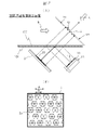
- 1 is a layout diagram showing a main part of a spatial floating image display device according to an embodiment of the present invention; FIG. 1 is a cross-sectional view showing the configuration of an image display device that constitutes a spatially floating image display device according to an embodiment of the present invention; FIG. It is a sectional view showing an example of concrete composition of a light source device.
- FIG. 4 is an explanatory diagram for explaining diffusion characteristics of an image display device
- FIG. 4 is an explanatory diagram for explaining diffusion characteristics of an image display device
- 1 is a cross-sectional view showing the configuration of an image display device that constitutes a spatially floating image display device according to an embodiment of the present invention
- FIG. It is a figure which shows an example of a concrete structure of the light source device which concerns on one Example of this invention.
- an image by image light from a large-area image light source is transmitted through a transparent member such as the glass of a show window that partitions the space, and floats inside or outside the space of the store.
- the present invention relates to a spatial floating image display device capable of displaying images.
- the present invention also relates to a large-scale digital signage system configured using a plurality of such spatial floating image display devices.
- the angle of divergence of the emitted image light is made small, that is, an acute angle, and furthermore, by aligning it with a specific polarized wave, only regular reflected light is efficiently reflected by the retroreflective member.
- the light utilization efficiency is high, and the ghost image that occurs in addition to the main space floating image, which was a problem with the conventional retroreflection method, can be suppressed, and a clear space floating image can be obtained.
- the apparatus including the light source of this embodiment can provide a novel and highly usable spatial floating image display apparatus that can greatly reduce power consumption.
- a space floating image display device capable of so-called unidirectional space floating image display, which is visible outside the vehicle through the shield glass including the windshield, rear glass, and side glass of the vehicle.
- conventional spatial floating image display devices combine an organic EL panel or liquid crystal display panel with a retroreflective member as a high-resolution color display image source.
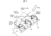
- the retroreflection member 2 Image light obliquely incident on the retroreflective sheet causes a ghost image, which impairs the image quality of the image floating in space.
- the retroreflective member (retroreflective portion 2a) shown as the prior art is a hexahedron, as shown in FIG. Multiple ghost images occur up to .
- the ghost image which is an image floating in the same space, is monitored by people other than the viewer, which poses a serious security problem.
- the spatially floating image obtained by reflecting the image light from the image display device having a narrow-angle directional characteristic, which will be described later, by the retroreflecting member can also be seen on the liquid crystal display panel as shown in FIG. A blur was visually recognized for each pixel.
- FIG. 1 shows an example of usage of a spatial floating image display device according to an embodiment of the present invention.
- FIG. 1A shows the overall configuration of the spatial floating image display device according to this embodiment.
- a space is partitioned by a show window (window glass 105), which is a translucent member (transparent member) such as glass.
- a show window window glass 105
- transparent member transparent member
- an aerial image (space floating image 3), which is a real image, is formed outside the store.
- the inside (inside the store) of the window glass 105 is shown in the depth direction, and the outside thereof (for example, the sidewalk) is in front.
- the specific polarized wave by providing means for reflecting the specific polarized wave on the window glass 105, it is possible to reflect the specific polarized wave and form an aerial image at a desired position in the store.
- FIG. 1(B) is a block diagram showing the configuration of the video display device 1 described above.
- the video display device 1 includes a video display unit 1a that displays an original image of an aerial image, a video control unit 1b that converts the input video in accordance with the resolution of the panel, and a video signal reception unit 1c that receives video signals. , and a receiving antenna 1d.
- the video signal receiving unit 1c supports wired input signals such as USB (Universal Serial Bus: registered trademark) input and HDMI (High-Definition Multimedia Interface: registered trademark) input, and supports Wi-Fi (Wireless Fidelity: registered trademark) ) and other wireless input signals, it also functions independently as a video reception and display device, and can also display video information from tablets, smartphones, etc. Furthermore, if a stick PC or the like is connected, it is possible to give it the ability to perform calculation processing and video analysis processing.
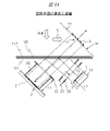
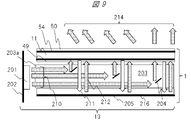
- FIG. 2 shows an example of the configuration of the main part and the configuration of the retroreflective part of the spatial floating image display device according to one embodiment of the present invention.
- the configuration of the spatially floating image display device will be described more specifically with reference to FIG.
- a transparent member 100 such as glass is provided with an image display device 1 that diverges image light of a specific polarized wave at a narrow angle in an oblique direction.
- the image display device 1 includes a liquid crystal display panel 11 and a light source device 13 that generates specific polarized light having narrow-angle diffusion characteristics.
- the image light of the specific polarized wave from the image display device 1 is reflected by the polarization separating member 101 having a film that selectively reflects the image light of the specific polarized wave provided on the transparent member 100, and is incident on the retroreflective member 2.
- the polarization splitting member 101 is formed in a sheet shape and adhered to the transparent member 100 .
- a ⁇ /4 plate 21 is provided on the image light incident surface of the retroreflective member 2 . The image light is passed through the ⁇ /4 plate 21 twice, ie when it enters the retroreflective member 2 and when it exits, so that the specific polarized wave is polarization-converted to the other polarized wave.
- the polarization separating member 101 that selectively reflects the image light of the specific polarized wave has the property of transmitting the other polarized light that has undergone polarization conversion, the image light of the specific polarized wave after the polarization conversion is used. passes through the polarization separation member 101 .
- the image light transmitted through the polarization separation member 101 forms a space floating image 3 which is a real image outside the transparent member 100 .
- the light forming the spatially floating image 3 is a set of light rays converging from the retroreflective member 2 to the optical image of the spatially floating image 3, and these rays continue straight after passing through the optical image of the spatially floating image 3. do. Therefore, the spatially floating image 3 is an image having high directivity, unlike diffuse image light formed on a screen by a general projector or the like. Therefore, in the configuration of FIG. 2, when the user views the image 3 in space from the direction of arrow A, the image 3 is viewed as a bright image. The floating image 3 cannot be visually recognized as an image at all. This characteristic is very suitable for use in a system that displays images that require high security or highly confidential images that should be kept secret from the person facing the user.
- the polarization axes of the reflected image light may become uneven.
- part of the image light whose polarization axes are not aligned is reflected by the polarization separation member 101 described above and returns to the image display device 1 .
- This light may be re-reflected on the image display surface of the liquid crystal display panel 11 constituting the image display device 1 , generate a ghost image, and degrade the image quality of the spatially floating image 3 . Therefore, in this embodiment, an absorptive polarizing plate 12 is provided on the image display surface of the image display device 1 .
- Image light emitted from the image display device 1 is transmitted through the absorptive polarizing plate 12 , and reflected light returning from the polarization separation member 101 is absorbed by the absorptive polarizing plate 12 .
- the re-reflection can be suppressed, and deterioration of the image quality due to the ghost image of the space-floating image can be prevented.
- the polarization separation member 101 described above may be formed of, for example, a reflective polarizing plate or a metal multilayer film that reflects a specific polarized wave.
- FIG. 2(B) shows the surface shape of the retroreflective member 2 manufactured by Nippon Carbide Industry Co., Ltd. used in this study as a representative retroreflective member 2 .
- the retroreflective member 2 light rays incident on the inside of the retroreflective portion 2a consisting of regularly arranged hexagonal prisms are reflected by the wall and bottom surfaces of the hexagonal prisms and emitted as retroreflected light in the direction corresponding to the incident light.
- a regular image R1 shown in FIG. 5 is formed.
- FIG. 3 depending on the image light obliquely incident on the retroreflective member 2 among the image light from the image display device 1, a ghost image (ghost image in FIG. G1-G6) are formed.
- the spatially floating image display device of this embodiment displays the spatially floating image 3, which is a real image, without forming a ghost image, based on the image displayed on the image display device 1 of the present invention.
- the resolution of this spatially floating image 3 largely depends on the resolution of the liquid crystal display panel 11 as well as the outer diameter D and the pitch P of the retroreflective portions 2a of the retroreflective member 2 shown in FIG. 2(B). For example, when a 7-inch WUXGA (1920 ⁇ 1200 pixels) liquid crystal display panel 11 is used, even if one pixel (one triplet) is approximately 80 ⁇ m, the diameter D of the retroreflective portion 2a is 240 ⁇ m and the pitch is 240 ⁇ m.
- the effective resolution of the spatially floating image 3 is reduced to about 1/3. Therefore, in order to make the resolution of the spatially floating image 3 equal to that of the image display device 1, it is desired that the diameter D and the pitch P of the retroreflection portion 2a be close to one pixel of the liquid crystal display panel. On the other hand, in order to suppress the occurrence of moire caused by the pixels of the retroreflective member 2 and the liquid crystal display panel 11, it is preferable to design the respective pitch ratios outside the integral multiple of one pixel. Further, it is preferable that the retroreflecting portion 2a is arranged so that no one side of the retroreflective portion 2a overlaps any one side of one pixel of the liquid crystal display panel 11. FIG.
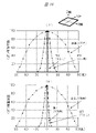
- the inventor investigated the relationship between the blur amount l of the image of the spatially floating image and the pixel size L, which is permissible for improving the visibility, using a liquid crystal display panel with a pixel pitch of 40 ⁇ m and a narrow divergence angle (divergence angle of 15°) of the present invention.
- the image display device 1 was prepared by combining the light source of .
- FIG. 4 shows the experimental results. It has been found that the blur amount l that deteriorates the visibility is preferably 40% or less of the pixel size L, and is almost inconspicuous if it is 15% or less.
- the surface roughness of the reflecting surface for which the amount of blur l is an allowable amount has an average roughness of 160 nm or less in the range of the measurement distance of 40 ⁇ m. It was found that 120 nm or less is desirable. Therefore, it is desirable to reduce the surface roughness of the retroreflective member 2 described above and reduce the surface roughness including the reflecting film forming the reflecting surface and its protective film to the above-described value or less.
- a roll press method for molding is a method of aligning the retroreflective portions 2a and forming them on a film.
- the reverse shape of the shape to be shaped is formed on the surface of the roll, and UV curable resin is applied on the base material for fixing and passed between the rolls to shape the desired shape and irradiate UV rays. and hardened to obtain a retroreflective member 2 having a desired shape.
- the image display device 1 of the present invention uses the liquid crystal display panel 11 and the light source device 13 that generates specific polarized light having a narrow-angle diffusion characteristic to be described later, so that an image is obliquely projected onto the retroreflective member 2 described above. It is possible to realize a structurally superior system in which the possibility of incident light is small, generation of a ghost image can be prevented, and even if a ghost image is generated, the brightness of the ghost image is low.
- FIG. 6A shows another example (second example) of the main configuration of the spatial floating image display device according to one embodiment of the present invention.
- the image display device 1 includes a liquid crystal display panel 11 as an image display element, and a light source device 13 for generating specific polarized light having narrow-angle diffusion characteristics.
- the liquid crystal display panel 11 is composed of a liquid crystal display panel of a selected size, from a small screen size of about 5 inches to a large liquid crystal display panel of over 80 inches. Image light from the liquid crystal display panel 11 is reflected toward the retroreflecting member 2 by a polarization separation member 101 such as a reflective polarizing plate.
- a ⁇ /4 plate 21 is provided on the light incident surface of the retroreflective member 2, and the image light is polarized by passing through the ⁇ /4 plate 21 twice. polarization.
- the other polarized wave after the polarization conversion is transmitted through the polarization separation member 101, and the space floating image 3, which is a real image, is formed and displayed outside the transparent member 100.
- FIG. An absorptive polarizing plate 112 is provided on the external light incident surface of the transparent member 100 .
- the retroreflection of light may cause the polarization axes to become uneven, so part of the image light is reflected and returned to the image display device 1 .
- an absorption polarizing plate 12 is provided on the image display surface of the image display device 1 .
- the absorptive polarizing plate 12 transmits the image light and absorbs the above-described reflected light, thereby preventing deterioration in image quality due to the ghost image of the space floating image 3 .
- the fourth light shielding member 25 is configured to block the incidence of the external light.
- the polarization separating member 101 is formed of a reflective polarizing plate or a metal multilayer film that reflects a specific polarized wave.
- a second light shielding member 23 and a third light shielding member for shielding oblique image light other than the normal image light (the normal image R1 in FIG. 5) forming the spatially floating image 3 are provided. 24 are attached.
- a first light shielding member 22 is also provided between the retroreflecting member 2 and the polarization separating member 101 to shield oblique image light other than normal image light.
- the fourth light shielding member 25 is also provided so that external light does not directly enter the retroreflective member 2, and blocks oblique light that causes ghost images. As a result, the generation of ghost images can be suppressed.
- the inner diameters of the second light shielding member 23 and the third light shielding member 24 were set to 110% of the area through which the regular image light flux forming the spatially floating image 3 passes. I was able to create and assemble within the range of In order to further reduce the occurrence of ghost images, it was possible to suppress the occurrence of ghost images to a practically negligible level by setting the light shielding member to 104% or less of the area through which the regular image light beam passes. .
- the first light shielding member 22 provided between the retroreflective member 2 and the polarized light separating member 101 is such that the distance L1 between the first light shielding member 22 and the retroreflective member 2 is set to the distance between the retroreflective member 2 and the polarized light separating member 101.
- the ratio is 50% or less, the generation of ghost images can be further reduced, and when the ratio is 30% or less, it can be visually observed to reduce the problem to a practically negligible level.
- the cross-sectional shape of the light shielding member in FIG. 6A indicates the effectiveness of the light shielding member for the area through which the regular image light flux forming the spatially floating image 3 passes (in this embodiment, this corresponds to the area through which the image light flux passes in the absorptive polarizing plate 112). It should be approximately the same size as the area. Further, the cross-sectional shape of the light shielding member is even better if a beam is provided toward the inner surface and the abnormal light that forms the ghost image is reflected multiple times on the surface of the beam to absorb the abnormal light.
- the area through which the normal image light flux passes is made smaller than the outer frame of the light shielding member, and is equal in area to the inscribed surface of the beam.
- the shape of the retroreflective member 2 may be a concave surface or a convex surface having a radius of curvature of 200 mm or more from a planar shape directly facing the image display device 1 .
- the ghost image generated after reflection may be kept away from the visual field of the viewer so that it cannot be viewed.
- the amount of light reflected normally decreases, and a new problem arises that the amount of peripheral light in the resulting spatial floating image 3 decreases. Therefore, in order to reduce the ghost image to a practically non-problematic level, it is preferable to select and apply the technical means described above or use them together.
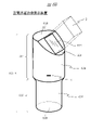
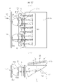
- FIG. 6B is a perspective view showing an example of the appearance of a spatially floating image display device (third example) according to one embodiment of the present invention.
- the spatially floating image display device shown in FIG. 6B has a generally tubular, particularly cylindrical housing 106 as shown.
- the space-floating image display device having this cylindrical housing 106 can be stored in a bottle holder (also called a drink holder. FIG. 6D described later) in a vehicle, and is relatively small (compact) and portable (portable).
- a spatial floating image display device In this cylindrical shape, the axis of the cylinder extends in the height direction (corresponding to the vertical direction, Z direction in FIG.
- the cylindrical housing 106 is roughly divided into an upper housing portion 601 and a lower housing portion 602, which are integrally connected. Inside the housing 106, an optical system and a control circuit board, which will be described later, and, if necessary, a rechargeable battery, etc., are accommodated.
- the cylindrical housing 106 has rigidity, light shielding properties, waterproof properties, etc., and has not only curved side surfaces 606 and 607 but also an upper surface 603 and a lower surface 608. space is closed.
- the cylindrical housing 106 has a height of about 20 cm, an upper housing upper portion 601 with a diameter of about 9 cm, and a lower housing lower portion 602 with a diameter of about 7 cm.
- the size of the spatially floating image 3 corresponds to the screen size of the liquid crystal display panel 11 and the size of the window portion 605, and can be, for example, 2 to 3 inches.
- a distance (distance 690 in FIG. 6C) corresponding to the optical path length from the window 605 to the formation position of the floating image 3 is, for example, about 6 cm.
- the diameter of the housing upper portion 601 is larger than the diameter of the housing lower portion 602 .
- This configuration takes into consideration that the housing lower portion 602 is housed in the bottle holder internal space and the housing upper portion 601 is exposed above the bottle holder.
- the upper housing portion 601 can accommodate the optical system in a volume larger than that of the lower housing portion 602 .
- it is easy to arrange a larger element and it is easy to secure a longer optical path length.
- a longer distance (distance 690 in FIG. 6C) can be secured.
- the screen size of the liquid crystal display panel 11 can be made larger, and the size of the spatially floating image 3 can be made larger accordingly.
- the relationship between the diameters of the lower housing part 602 and the upper housing part 601 is not limited to the above. A configuration in which the diameter of the housing upper portion 601 is reduced is also possible.
- the housing upper part 601 has a shape in which a part of a cylinder including an upper surface 603 and a side surface 606 is obliquely cut away.
- a ramp 604 is provided, such as a generally semi-circular area.
- the slope 604 is provided with a rectangular window (in other words, an opening) 605 in which the transparent member 100 and the like are arranged.
- a window (opening) 605 is a portion for emitting image light to the outside.
- the image light from the optical system in the housing 106 passes through this window (opening) 605 and forms a floating image 3 at a predetermined distance outside the housing 106 as shown.
- the shape of the window (opening) 605 is rectangular as an example, it is not limited to this, and various shapes such as a circle, an ellipse, and a polygon are possible.
- the angles of the slope 604 and the window 605 are, for example, about 45 degrees with respect to the upper surface 603 (angle ⁇ 3 in FIG. 6C).
- the optical axis of the spatially floating image 3 (optical axis A3 in FIG. 6C) is set obliquely upward (direction W in FIG. 6C) at about 45 degrees from the horizontal plane.
- the angle and direction of the slope 604 and the arrangement of the optical axis are such that when this spatial floating image display device is installed in the bottle holder (FIG. 6D) in the vehicle, it is easy to face the driver. Designed.
- the configuration of the angle and direction of the slope 604 and the arrangement of the optical axis is not limited to this.
- the angle ⁇ 3 and the elevation angle of the optical axis A3 may be set within a predetermined angle range (for example, 45° ⁇ 15°).
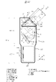
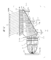
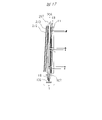
- FIG. 6C shows an internal configuration example of the portable spatial floating image display device shown in FIG. 6B.
- An upper housing portion 601 mainly accommodates an optical system for generating the spatially floating image 3
- a lower housing portion 602 mainly accommodates a control board 610 and a rechargeable battery 611 .
- the control board 610 and elements such as the image display device 1 of the optical system are connected to each other by signal lines or the like.
- the upper part 601 of the housing is equipped with an optical system for generating a spatially floating image 3 with high visibility without ghost images.
- the optical system of the housing upper part 601 includes the image display device 1 (the light source device 13, the liquid crystal display panel 11, and the absorptive polarizing plate 12 in FIG. 6C), the plane mirror 4, and the beam splitter (in other words, the polarization separating member). 101 , the retroreflective member 2 and the ⁇ /4 plate 21 as a retardation plate, the transparent member 100 and the absorptive polarizing plate 112 .
- a rechargeable battery 611 in the lower part of the housing 602 is a rechargeable battery such as a lithium ion battery and a power supply circuit.
- the control board 610 is a control circuit board that configures a video control unit, a video/audio signal transmission/reception unit, and the like, and includes a processor, a memory, an interface, and the like.
- the control board 610 is arranged vertically, for example, in a partial region inside the housing lower portion 602 .
- the control board 610 may have a communication interface function, and may transmit/receive data to/from the Internet or the like.
- the housing lower part 602 of the housing 106 is accommodated in the bottle holder.
- an optical system is housed in the housing upper part 601 in the vertically long cylindrical housing 106, and a rechargeable battery 611, which is relatively heavier than the optical system, is housed in the housing lower part 602.
- a rechargeable battery 611 which is relatively heavier than the optical system, is housed in the housing lower part 602. It is The center of gravity of the spatially floating image display device as a whole exists below. As a result, the spatial floating image display device can be stably held in the bottle holder. In addition, this spatially floating image display device is relatively stable against vibrations such as shaking of the vehicle.
- the length in the height direction of the upper housing portion 601 is greater than the length in the height direction of the lower housing portion 602 .
- the length of the upper housing portion 601 in the height direction is limited to a certain length in consideration of stably holding the apparatus with the lower housing portion 602 accommodated in the bottle holder.
- the input/output terminal 5 is provided at one location on the side surface 606 of the housing upper portion 601 of the housing 106, for example. Input/output terminal 5 is connected to control board 610 .
- the input/output terminal 5 is a power supply input and signal input/output terminal, such as a USB terminal, but is not limited thereto.
- This input/output terminal 5 is provided as a terminal for supplying power from, for example, a cigarette lighter socket of a vehicle, and a terminal for taking in various information including a video signal for outputting as a floating image 3 (concierge, etc.). It is The control board 610 supplies a video signal input from the outside through the input/output terminal 5 to the video display device 1 . Alternatively, a video signal input from the outside through the input/output terminal 5 may be directly supplied to the video display device 1 .
- the input/output terminal 5 may be provided as a plurality of input/output terminals divided into a power supply input terminal and a signal input/output terminal.
- the position of the input/output terminal 5 may be any position on the housing 106 .
- the position of the input/output terminal 5 may be one place on the upper surface 603 or one place on the side surface 607 of the lower housing part 602 . In this embodiment, even when the lower housing part 602 is accommodated in the drink holder, the input/output terminals 5 of the upper housing part 601 can be easily handled.
- An in-vehicle power supply can be connected to the input/output terminal 5 .
- An external power supply input from an in-vehicle power source (for example, a cigar socket) is supplied to the rechargeable battery 611 through the input/output terminal 5, and the rechargeable battery 611 is charged.
- a rechargeable battery 611 supplies power to each unit such as the control board 610 . Since this space floating image device is small, a dry battery may be used as the rechargeable battery 611 .
- Input information from the outside such as input information from a car navigation system, is input to the control board 610 through the input/output terminal 5 . Based on the input information, the control board 610 creates an image such as a concierge to be displayed as the spatial floating image 3 and a corresponding sound, and controls the image display device 1 and the like.
- This spatial floating image display device can also be controlled by voice.
- a device such as a microphone or a speaker may be connected to the input/output terminal 5 of the housing 106, or a controller for a car navigation system or an in-vehicle system may be connected.
- a user's smart phone or the like may be connected.
- voice input/output control is possible based on the control of the microphone or the like by the control board 610 . That is, the control board 610 is capable of inputting a voice uttered by the driver or the like from a microphone or the like, recognizing the input voice, and performing processing corresponding to the recognized predetermined instruction (for example, turning on/off the display). .
- control board 610 reads the sound associated with the floating image 3 (for example, the sound emitted by the concierge) or creates it by the sound synthesis function, and outputs it to the driver etc. from the speaker etc. can be output to
- the configuration is not limited to these, and a configuration in which a microphone, a speaker, or the like is mounted on the housing 106 of the spatially floating image display device may be employed.
- FIG. 6D shows an appearance example of a state in which the portable spatial floating image display device of this embodiment is installed in a cylindrical bottle holder 600H inside a vehicle.
- a person such as a driver or a fellow passenger in the vehicle inserts and stores the lower housing portion 602 of the floating image display device into the bottle holder 600H in the vehicle.
- the upper part 601 of the housing is projected upward from the bottle holder 600H, and the image light emitted from the window 605 forms the floating image 3 in space.
- the floating image is displayed on the bottle holder 600H.
- the direction of the window 605 of the floating image display device of the bottle holder 600H (that is, the direction of the optical axis of the image light, the direction of the floating image 3) is the face of the driver in the right driver's seat. ⁇ It shows a state adjusted so as to face the eyes. This orientation can be adjusted by, for example, rotating the cylindrical housing 106 within the bottle holder 600H.
- the orientation of the window 605 may be adjusted so as to match the face and eyes of the fellow passenger.
- the bottle holder 600H is not limited to a vehicle-mounted type, and there are types that can be attached and detached. It is possible.
- the configuration of the optical system inside the housing 106 is designed according to the cylindrical housing 106 suitable for installation in the bottle holder 600H.
- Each element of the optical system is arranged so as to correspond to a space that is long in the height direction inside the cylindrical housing 106 (especially the upper housing portion 601). is an optical system that secures an optical path length as long as possible.
- the image display device 1, the plane mirror 4, the beam splitter 101, the retroreflecting member 2, the transparent member 100, and the like are arranged in an approximate order from the bottom to the top in the height direction in the upper part 601 of the housing. .
- Each element is fixed to the housing upper part 601 in a predetermined relationship. More specifically, for example, the beam splitter 101, the retroreflective member 2, and the transparent member 100 (installed in the window portion 605) are in contact with each other on one side, or are separated from each other by a predetermined interval. are placed in close proximity.
- the housing 106 has a shape that is longer in the height direction than in the radial direction, and each element constituting the optical system is arranged as shown in the drawing so as to secure the optical path of the image light as long as possible in the height direction.
- the image display device 1, the flat mirror 4, the retroreflection member 2, and the like are arranged in a state of being inclined with respect to the height direction and the like.
- the image display device 1 is arranged at an angle ⁇ 1.
- the retroreflective member 2 is arranged at an angle ⁇ 2.
- the beam splitter 101 is arranged horizontally.
- the slope 604 and the transparent member 100 are arranged at an angle ⁇ 3.
- the plane mirror 4 is also arranged at an angle ⁇ 4 in which the plane is slightly inclined with respect to the vertical plane.
- the optical path of the image light in this optical system is the optical path reflected by the plane mirror 4 .
- the optical path of the image light of this optical system is an optical path in which a beam splitter 101 is arranged between the flat mirror 4 and the retroreflective member 2 .
- the optical path of the image light of this optical system is from the image display device 1 to the plane mirror 4, the beam splitter 101, the ⁇ /4 plate 21, the retroreflection member 2, the ⁇ /4 plate 21, the beam splitter 101, and the transparent member 100 in this order. , an optical path leading to the floating image 3 via the absorbing polarizing plate 112 .
- Points p1 to p6 are examples of points through which the image light passes on the optical path.
- a point p1 is a reference point (for example, the center point) of the image exit surface of the liquid crystal display panel 11 .
- Point p2 is the reference point of plane mirror 4 .
- a point p3 is a reference point of the beam splitter 101 .
- a point p4 is a reference point of the retroreflective member 2 .
- a point p5 is a reference point of the transparent member 100 .
- a point p6 is a reference point of the spatially floating image 3 . This spatially floating image 3 can be best visually recognized when viewed by the user's eyes from the direction of the arrow A corresponding to the optical axis A3 (the direction directly facing the image plane).
- the spatially floating image display device shown in FIG. 6B and the like generates the spatially floating image 3 at a predetermined distance diagonally above the housing 106 .
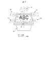
- the space-floating image 3 for example, the face of a person (concierge) who provides the driver of the vehicle with navigation information and POI information existing around the vehicle by video and audio is displayed.
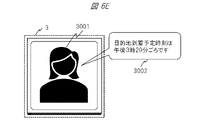
- FIG. 6E schematically shows a display example of the concierge in the space floating image 3 as seen from the driver.
- the spatially floating image 3 has, for example, a rectangular area of a predetermined maximum size, and a concierge image 3001 is displayed within the area.
- the image 3001 may be a moving image or a still image.
- a voice 3002 (for example, a guide for the estimated time of arrival at the destination) emitted by the concierge is output from a speaker (an in-vehicle speaker or a speaker housed in the housing 106 of the floating image display device in space) or the like. output.
- the image display device 1 includes a liquid crystal display panel 11 as an image display element and a light source device 13 that generates specific polarized light having narrow-angle diffusion characteristics.
- the liquid crystal display panel 11 is composed of a small one with a screen size of about 2 to 3 inches.
- an absorptive polarizing plate 12 is further provided on the image display surface of the image display device 1 .
- an antireflection film (not shown) on the image output side of the absorptive polarizer 12 provided on the surface of the image display device 1, the light of the ghost image is transmitted and absorbed by the absorptive polarizer 12. , and has a configuration capable of preventing deterioration in image quality due to a ghost image.
- the image display device 1 composed of the liquid crystal display panel 11, the absorptive polarizing plate 12, and the light source device 13 is arranged with respect to the housing 106 at a predetermined angle (the optical axis is at an angle ⁇ 1 with respect to the horizontal plane) as shown in the drawing. ⁇ It is fixed.
- the light source device 13 functions as a backlight that supplies the liquid crystal display panel 11 with illumination light having narrow-angle diffusion characteristics.
- Image light from the image display device 1 (point p1 with respect to the optical axis) is reflected on the plane mirror 4 (point p2) to change direction and enter the beam splitter 101 (point p3).
- the image light further passes through the beam splitter 101 (point p3) and travels directly toward the retroreflective member 2 (point p4).
- the light source light from the light source device 13 is S-polarized (vertically polarized) (FIG. 8) and P-polarized (parallel polarized) (FIG. 9).
- the light source light from the light source device 13 functions as a backlight for the liquid crystal display panel 11 .
- the image light emitted from the image display device 1 (liquid crystal display panel 11) (that is, the image light modulated by the signal of the image source in the liquid crystal display panel 11 based on the light source light) is S-polarized. and P-polarized light.
- the image light from the image display device 1 is image light having P-polarization characteristics will be described.
- the image light (P-polarized light) is reflected on the plane mirror 4 and directed toward the beam splitter 101 along the optical axis A2.
- the beam splitter (polarization separation member) 101 has a polarization separation function, and when the image light from the liquid crystal display panel 11 having the light source device 13 as a backlight, that is, the image display device 1, is P-polarized light, it is transmitted. However, in the case of S-polarized light, the element has a structure that reflects (in other words, does not transmit) the light.
- a beam splitter 101 is formed of a reflective polarizing plate or a multilayer film that reflects a specific polarized wave.
- the multilayer film of this example is a metal multilayer film.
- the image light (for example, P-polarized light) transmitted through the beam splitter 101 is directed toward the retroreflective member 2 .
- a ⁇ /4 plate 21 is provided on the light incident surface of the retroreflective member 2 .
- the image light (P-polarized light) from the beam splitter 101 as the image light (P-polarized light) from the image display device 1 passes through the ⁇ /4 plate 21 at the time of incidence on the retroreflective member 2 and at the time of emission after reflection. Passed twice. Thereby, the image light is polarization-converted from one polarized wave to the other polarized wave. Specifically, P-polarized light is converted into S-polarized light.
- the image light reflected by the retroreflection member 2 becomes image light having S-polarization characteristics (image light with polarization characteristics different from the original image light) and travels toward the beam splitter 101 .
- the image light (S-polarized light) is reflected by the beam splitter 101 and travels toward the transparent member 100 along the optical axis A3.
- the image light (S-polarized light) passes through the transparent member 100 and the absorptive polarizing plate 112 of the window section 605 to the outside, and the space-floating image 3, which is a real image, is displayed at a predetermined distance 690 outside the window section 605. is generated and displayed.
- the image light from the image display device 1 is S-polarized light
- S-polarized light which is image light emitted from the image display device 1
- the beam splitter 101 in this case is an element having a structure that transmits image light (S-polarized light) from the image display device 1 and reflects P-polarized light.
- the image light (S-polarized light) from the beam splitter 101 is polarized by being reflected by the retroreflective member 2 and passing through the ⁇ /4 plate 21 twice, resulting in P-polarized light.
- This image light (P-polarized light) is reflected by the beam splitter 101 toward the transparent member 100 , passes through the transparent member 100 and the like, and forms a floating image 3 .
- the above image light and the polarization of the beam splitter 101 and the like can be designed in any embodiment.
- the image light from the image display device 1 is S-polarized light
- the reflectance of the plane mirror 4 is higher.
- the image light from the image display device 1 is P-polarized light
- the floating image 3 can be easily viewed even when the user wears polarized sunglasses.
- the portable spatial floating image display device of this embodiment when the portable spatial floating image display device of this embodiment is installed in a vehicle, external light (sunlight or external illumination light) entering from the outside of the vehicle is projected onto the windshield (windshield). It is known that most (approximately 80%) of the S-polarized component of the external light is reflected, and the external light entering the interior of the vehicle contains a large amount of the P-polarized component. Therefore, it is preferable to provide an absorptive polarizing plate 112 on the external light incident surface of the transparent member 100 .
- the window part 605 transmits image light.
- the transparent member 100 is provided in the window portion 605 and is composed of a glass plate or the like.
- An absorption polarizing plate 112 is provided on the external light incident surface of the transparent member 100 .
- a transparent member 100 and an absorptive polarizing plate 112 are arranged in a portion of the window portion 605 of the slope 604 through which the image light passes, and the other portion (that is, a portion of the housing 106) is exposed to outside light. It is composed of a light shielding member so as not to enter the inside 106 .
- the size of the window portion 605 and the size of the spatial floating image 3 correspond to each other.
- a part (the part through which image light passes) may be formed of a transparent material, and the other part may be formed of a light shielding member.
- An absorptive polarizing plate 112 is provided on the outer surface of the transparent member 100 in order to reduce deterioration in image quality due to external light such as sunlight and illumination light from the outside of the housing 106 that houses the image display device 1 and other optical components. set up. Most of the external light is absorbed by the absorptive polarizing plate 112 and hardly enters the upper part 601 of the housing.
- the polarization axes may become uneven due to the retroreflection of the light, so part of the image light is reflected and returns to the image display device 1 .
- This light is reflected again by the image display surface of the liquid crystal display panel 11 that constitutes the image display device 1, causing the above-described ghost image and significantly degrading the image quality of the spatially floating image 3.
- an absorptive polarizing plate 12 is further provided on the image display surface of the image display device 1 .
- the light of the ghost image is transmitted and absorbed by the absorptive polarizing plate 12. , to prevent deterioration of image quality due to ghost images.
- the retroreflective member 2 is disposed obliquely downward at an angle ⁇ 2, and the transparent member 100 of the window 605 and the retroreflective member 2 (particularly, the retroreflective surface) are aligned. , are arranged in a relationship of about 90 degrees as shown in the figure.
- the main incident direction of the external light component entering the interior through the transparent member 100 of the window 605 from the outside is the same direction as the optical axis A3 of the image light (the direction perpendicular to the plane of the transparent member 100).
- the retroreflective member 2 and the ⁇ /4 plate 21 are arranged so that the direction of the optical axis of the retroreflective member 2 (perpendicular to the plane) has a relationship of about 90 degrees.
- the retroreflective member 2 and the ⁇ /4 plate 21 are arranged such that the retroreflective surface of the retroreflective member 2 and the surface of the transparent member 100 have a relationship of about 90 degrees.
- the retroreflective member 2 is arranged downward (about 90 degrees in FIG. 6C) with respect to the window 605 through which the external light enters. Therefore, it is difficult for the external light component to directly enter the retroreflective member 2 . Therefore, the occurrence of a strong ghost image can be prevented by the configuration of the optical system that prevents the incidence of external light.
- the image display device 1 is also arranged at a position away from the window 605 with the beam splitter 101 and the plane mirror 4 interposed therebetween.
- the image display device 1 is arranged at a position where the image light of the optical axis A1 emitted from the image display device 1 cannot be visually recognized through the window portion 605 from the direction of the arrow A (optical axis A3). This further reduces the occurrence of ghost images.
- the optical path length from the point p1 of the image display device 1 to the point p3 of the beam splitter 101 via the point p2 of the flat mirror 4 and the point p6 of the floating image 3 from the point p3 of the beam splitter 101 is correlated with the optical path length of the optical path to If the distance 690 for forming the spatially floating image 3 outside the window portion 605 is secured to some extent, the sense of floating of the spatially floating image 3 can be enhanced. Therefore, in this embodiment, as an optical system to be housed and arranged in a small and vertically long housing 106, each element is obliquely arranged and a plane mirror 4 is provided, so that the image display device 1 is connected to the beam splitter. The optical path length up to 101 is secured as long as possible.
- Cylindrical housing 106 can be suitably installed in a bottle holder that is standardly installed in a general vehicle or an attachable/detachable type bottle holder. A user can easily attach/detach this spatially floating image display device to/from a bottle holder or similar container or space as required. Further, since the housing 106 is provided with the input/output terminal 5, the spatially floating image display device can supply power to the rechargeable battery 611 from a power source such as a cigarette lighter socket of the vehicle. Therefore, this device can always be recharged even during operation, and there is no concern that the battery will run out even when used for a long period of time.
- the spatially floating image 3 formed by the spatially floating image display device of this embodiment has directivity with respect to the viewing direction in the same manner as described above.
- the driver and passengers in the vehicle view the spatially floating image 3, in order for them to be able to appropriately view the bright image, they should be positioned directly in front of the spatially floating image 3, as indicated by the arrow A in FIG. 6C. It is most desirable to view from the facing direction (the direction matching the optical axis A3).
- the orientation of this spatially floating image 3 (optical axis A3) also depends on the conditions such as the position and orientation of this device installed on the drink holder.
- the relative orientation when the driver or the like views the floating image 3 depends on the position and orientation of the floating image 3 (optical axis A3) and the position and orientation of the driver's face and eyes. Depends on relationship.
- the spatially floating image 3 will be displayed by the driver.
- the window 605 of the slope 604 and the corresponding optical system are designed so that it can be easily adjusted to face and eyes. That is, the window portion 605 of the slope 604 is formed at about 45 degrees, and the optical axis A3 of the spatially floating image 3 is oriented obliquely upward at about 45 degrees.
- the driver or the like can easily view the spatially floating image 3 as a bright image from the direction directly in front without moving the head or the like so much.
- the driver or the like needs to adjust the image light in order to properly view the spatially floating image from the front. For example, it is necessary to look in by moving the head etc. according to the direction of . According to the present embodiment, there is no such need, and the bright spatial floating image 3 can be viewed in a relatively natural posture even while driving.
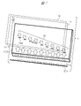
- FIG. 6F shows a configuration example in which the housing 106 is provided with a lid as a modification of the above embodiment.
- a lid 651 like a bottle cap is provided in the upper part 601 of the housing so that the upper surface 603 and the window part 605 can be hidden according to the user's operation.
- the lid 651 is attached to prevent the window portion 605 from being scratched or dust-attached, and the strength of the window portion 605 can be increased.
- the lid 651 is removed.
- FIG. 6F has a lid 652 provided on the window 605 in the upper part 601 of the housing as another configuration example.
- the shape of the lid 652 is, for example, a flat plate.
- One side of the lid 652 is connected to a hinge provided on the side where the upper surface 603 and the inclined surface 604 (FIG. 6B) are in contact with each other, and rotates around the hinge as a rotation axis according to the user's operation.
- the window 605 is covered with a cover 652 as shown in the figure, so that the window 605 can be prevented from being scratched or dusted, and the strength of the window 605 can be increased. can be done.
- the lid 652 is rotated as indicated by an arrow to be placed on the upper surface 603 and the window 605 is opened.
- FIG. 6F has a cover 653 provided in a space area obtained by notching a part of the cylinder near the window 605 in the upper part 601 of the housing as another configuration example.
- the lid 653 may have a structure that rotates in the same manner as the lid 652, but may also have a structure that is attached to a projection or the like provided on a surface of the slope 604 other than the window portion 605, as shown in the drawing.
- the window 605 is covered with a lid 653 as shown in the figure, so that the window 605 can be prevented from being scratched or dusted, and the strength of the window 605 can be increased. can be done.
- the lid 653 is removed and the window 605 is opened.
- the housing 106 of the spatial floating image display device may be provided with not only a lid but also a handle for carrying.
- the cylindrical housing 106 is not limited to a cylindrical shape, and various horizontal cross-sectional shapes are possible.
- the cross-sectional shape of the housing 106 may be rectangular (or polygonal), for example, and the housing 106 may have a rectangular parallelepiped shape.
- the rectangular parallelepiped housing 106 is advantageous in that it is easy to manufacture and easy to hold.
- the beam splitter 101, the retroreflecting member 2, and the transparent member 100 of the window 605 are arranged so that their sides are in contact with each other like a triangle in consideration of further miniaturization.
- the sides of these elements may be spaced apart from each other.
- this portable spatial floating video device is not limited to this, and can be used in various places because it can be carried by the user.
- this portable spatial floating video device can be used in various places because it can be carried by the user.
- it can be used by similarly installing it on a container or the like other than the bottle holder.
- it can be used even when it is simply placed on a desk or the like without being housed in a container.
- a super-directional speaker may be used as a speaker for the spatially floating image display device.
- a super-directional speaker is a speaker that outputs super-directive sound so that the output sound can be heard only in a specific spatial region near the user's ear.
- the spatial floating image display device may include a camera and a distance measuring sensor, which are used to detect a touch operation or the like of the user's finger or the like on the spatial floating image 3, and perform predetermined processing according to the detection. It is good also as a structure to carry out.
- the spatial floating image display device may detect the presence or absence of the user based on the camera image or sensor detection, or may be configured to perform user authentication by analyzing and judging the user's face or the like.
- the floating image display device reads a code such as a bar code from the card or paper based on the camera image. Processing according to the code may be performed.
- a light shielding member may be arranged to shield image light having a divergence angle exceeding a specific angle from the liquid crystal display panel 11 from entering the retroreflective member 2 .
- the light source device 13 in the present embodiment should particularly have the following configuration (details will be described later).
- the light source device 13 includes a point-like or planar light source, optical means for reducing the angle of divergence of light from the light source, polarization conversion means for aligning the light from the light source into polarized light in a specific direction, and the light from the light source to a liquid crystal display. and a light guide having a reflective surface that propagates to the display panel 11. Light is controlled by the shape and surface roughness of the reflective surface of the light source device 13, so that image light from the liquid crystal display panel 11 has a narrow divergence angle. is configured to emit an image light flux having a
- the surface roughness of the retroreflective surface of the retroreflective member 2 is set to 160 nm or less.
- ⁇ Reflective polarizing plate> When the beam splitter 101 in this embodiment is a reflective polarizing plate with a grid structure, the characteristics of the light from the direction perpendicular to the polarization axis are degraded. For this reason, specifications along the polarization axis are desirable, and the light source device of this embodiment, which can emit image light emitted from the liquid crystal display panel 11 at a narrow angle, is an ideal light source. Also, the characteristics in the horizontal direction are similarly degraded with respect to oblique light.
- the image display device 1 of this embodiment shown in FIG. 1 includes a liquid crystal display panel 11 as an image display element and a light source device 13 that constitutes the light source of the liquid crystal display panel 11 .
- 7 shows the light source device 13 together with the liquid crystal display panel 11 as an exploded perspective view.
- the liquid crystal display panel 11 has a narrow-angle diffusion characteristic, that is, has a strong directivity (in other words, straightness) due to the light from the light source device 13, which is a backlight device. Moreover, an illumination light beam having characteristics similar to laser light whose plane of polarization is aligned in one direction is obtained, and image light modulated in accordance with an input image signal is emitted. As a result, as shown in FIG. 1, the emitted image light is reflected by the retroreflection member 2 and transmitted through the window glass 105 to form a space floating image 3 which is a real image.
- the image display device 1 includes a liquid crystal display panel 11, a light direction conversion panel 54 for controlling the directivity of the light flux emitted from the light source device 13, and a narrow-angle diffusion plate (not shown). That is, polarizing plates are provided on both sides of the liquid crystal display panel 11, and as indicated by arrows 30 in FIG. there is As a result, the image display device 1 projects a desired image as light of a specific polarized wave with high directivity (straightness) toward the retroreflective member 2 via the light direction conversion panel 54, and the retroreflective member After being reflected at 2, it is transmitted toward the viewer's eyes outside the space of the store in FIG.
- a protective cover 50 may be provided on the surface of the light direction conversion panel 54 described above.
- the light source device 13 and the liquid crystal display panel 11 are included in order to improve the utilization efficiency of the light flux emitted from the light source device 13 indicated by the arrow 30 in FIG. 7 and to significantly reduce the power consumption.
- the image display device 1 the light indicated by the arrow 30 from the light source device 13 is projected toward the retroreflective member 2 in FIG. (not shown) can also control the directivity so as to form the spatially floating image 3 at a desired position.
- this transparent sheet controls the imaging position of the spatially floating image while imparting high directivity by an optical component such as a Fresnel lens or a linear Fresnel lens.
- the image light from the image display device 1 efficiently reaches the observer outside the window glass 105 (for example, on the sidewalk) with high directivity (straightness) like a laser beam.
- the image display device 1 including the LED (Light Emitting Diode) element 201 of the light source device 13 it is possible to display a high-definition spatial floating image at a high resolution and significantly reduce the power consumption of the image display device 1 including the LED (Light Emitting Diode) element 201 of the light source device 13 .
- FIG. 8 shows another example of the image display device 1 .
- the light source device 13 is made of, for example, plastic, and includes an LED element 201 and a light guide 203 inside.
- the end face of the light guide 203 is gradually cut off toward the light receiving part in order to convert the diverging light from each LED element 201 into a substantially parallel light flux.
- a lens shape is provided that has a shape that increases the area and that has the effect of gradually decreasing the divergence angle by performing total reflection multiple times while propagating inside.
- a liquid crystal display panel 11 constituting the image display device 1 is attached to the upper surface of the light guide 203 .
- an LED element 201 as a semiconductor light source and an LED substrate 202 on which a control circuit for the LED element 201 is mounted are attached to one side surface of the case of the light source device 13 (the left end surface in FIG. 8 in this example).
- a heat sink which is a member for cooling the heat generated by the LED elements 201 and the control circuit, may be attached to the outer surface of the LED substrate 202 .
- the frame (not shown) of the liquid crystal display panel 11 attached to the upper surface of the case of the light source device 13 includes the liquid crystal display panel 11 attached to the frame and the liquid crystal display panel 11 electrically connected to the liquid crystal display panel 11.
- FPC Flexible Printed Circuits: flexible wiring board
- a new image display device 1 that is similar to a surface emitting laser image source driven by an image signal can be obtained.
- FIGS. 8 and 9 are sectional views, only one LED element 201 constituting the light source is shown.
- Light from the plurality of LED elements 201 is converted into substantially collimated light (substantially parallel light) by the shape of the light receiving end surface 203 a of the light guide 203 .
- the light-receiving portion on the end surface of the light guide and the LED element 201 are attached while maintaining a predetermined positional relationship.
- Each of the light guides 203 is made of translucent resin such as acryl.
- the LED light receiving surface at the end of the light guide has, for example, a conical convex outer peripheral surface obtained by rotating the parabolic cross section, and the top has a convex portion ( In other words, it has a concave portion formed with a convex lens surface), and has an outwardly projecting convex lens surface (or an inwardly concave lens surface may be used) in the central portion of the planar portion.
- the outer shape of the light receiving portion of the light guide 203 to which the LED element 201 is attached has a parabolic shape forming a conical outer peripheral surface, and the light emitted from the LED element 201 in the peripheral direction is totally reflected inside. The angle is set within the range of possible angles, or a reflective surface is formed.
- the LED elements 201 are arranged at predetermined positions on the surface of an LED board 202 which is a circuit board for the LED elements 201 .
- the LED substrate 202 is arranged and fixed to the LED collimator (the light receiving end surface 203a of the light guide 203) so that the LED elements 201 on the surface thereof are positioned in the central portion of the recesses described above.
- the shape of the light receiving end surface 203a of the light guide 203 makes it possible to extract the light emitted from the LED element 201 as substantially parallel light, thereby improving the utilization efficiency of the generated light. Become.
- the light source device 13 is configured by attaching a light source unit, in which a plurality of LED elements 201 as light sources are arranged, to the light receiving end surface 203a, which is a light receiving portion provided on the end surface of the light guide 203. Divergent light beams from the light receiving end surface 203a of the light guide body 203 are converted into substantially parallel light beams by the light receiving end surface 203a of the light guide body 203. 204 , the light is emitted toward the liquid crystal display panel 11 arranged substantially parallel to the light guide 203 .
- the uniformity of the luminous flux incident on the liquid crystal display panel 11 can be controlled.
- the luminous flux direction changing means 204 described above converts the luminous flux propagating in the optical waveguide 203 by providing a portion having a different refractive index, for example, in the shape of the surface of the optical waveguide 203 or in the interior of the optical waveguide 203.
- the light is emitted toward the liquid crystal display panel 11 arranged substantially parallel to 203 .
- the liquid crystal display panel 11 faces the center of the screen and the viewing point is placed at the same position as the diagonal dimension of the screen, if the relative luminance ratio is 20% or more when comparing the luminance between the center of the screen and the peripheral part of the screen, There is no problem in practical use, and if it exceeds 30%, the characteristics are even more excellent.
- FIG. 8 and 9 are cross-sectional views for explaining the configuration and operation of the light source (light source device 13) of this embodiment that converts polarization in the light source device 13 including the light guide 203 and the LED element 201 described above. It is a layout diagram. 8 shows the case of conversion from P-polarized light to S-polarized light, and FIG. 9 shows the case of conversion from S-polarized light to P-polarized light.
- the light source device 13 includes, for example, a light guide 203 formed of plastic or the like and provided with a light beam direction converting means 204 on its surface or inside, an LED element 201 as a light source, a reflective sheet 205, a phase difference It is composed of a plate 216, a lenticular lens, and the like, and the liquid crystal display panel 11 having polarizing plates on the light source light entrance surface and the image light exit surface is attached to the upper surface of the light source device 13 (light guide 203).
- a light guide 203 formed of plastic or the like and provided with a light beam direction converting means 204 on its surface or inside, an LED element 201 as a light source, a reflective sheet 205, a phase difference It is composed of a plate 216, a lenticular lens, and the like, and the liquid crystal display panel 11 having polarizing plates on the light source light entrance surface and the image light exit surface is attached to the upper surface of the light source device 13 (light guide 203).
- a film or sheet-like reflective polarizing plate 49 is provided on the light source light incident surface (lower surface) of the liquid crystal display panel 11 facing the light source device 13 .
- a polarized wave (for example, P wave) 212 on one side is selectively reflected, reflected by a reflective sheet 205 provided on one (lower) surface of the light guide 203, and directed toward the liquid crystal display panel 11 again.
- a ⁇ /4 plate as a retardation plate 216 is provided, and the light is reflected by the reflective sheet 205, and the light is reflected twice.
- the reflected light flux is converted from P-polarized light to S-polarized light, thereby improving the utilization efficiency of the light source light as image light.
- the image light beam whose light intensity has been modulated by the image signal on the liquid crystal display panel 11 is incident on the retroreflective member 2 in FIG.
- a spatial floating image 3, which is a real image, can be obtained inside or outside the space.
- a film or sheet-like reflective polarizing plate 49 is provided on the light source light incident surface (lower surface) of the liquid crystal display panel 11 facing the light source device 13 .
- polarized wave (for example, S wave) 211 is selectively reflected, reflected by a reflecting sheet 205 provided on one (lower) surface of the light guide 203, and directed toward the liquid crystal display panel 11 again.
- a ⁇ /4 plate as a retardation plate 216 is provided, and the light is reflected by the reflective sheet 205, and the light is reflected twice.
- the reflected light beam is converted from S-polarized light to P-polarized light, thereby improving the utilization efficiency of the light source light as image light.
- the image light beam intensity-modulated by the image signal on the liquid crystal display panel 11 is incident on the retroreflective member 2 in FIG.
- a spatially floating image 3, which is a real image, can be obtained inside or outside the .
- the reflective polarizing plate 49 provided on the light incident surface of the facing liquid crystal display panel 11 acts and the reflective polarizing plate 49 reflects the polarized component on one side.
- the theoretically obtained contrast ratio is obtained by multiplying the reciprocal of the cross transmittance of the reflective polarizing plate 49 and the reciprocal of the cross transmittance obtained by the two polarizing plates attached to the liquid crystal display panel 11 .
- This provides high contrast performance.
- FIG. 10 shows another example of a specific configuration of the image display device 1.
- the light source device 13 in FIG. 10 has the same configuration as the light source device in FIG. 12 and the like which will be described later.
- the light source device 13 is configured by housing an LED, a collimator, a synthetic diffusion block, a light guide, etc. in a case made of plastic, for example, and a liquid crystal display panel 11 is attached to the upper surface. 12 and 13, and an LED substrate 102 mounted with a control circuit thereof are attached to one side surface of the case of the light source device 13.
- a heat sink 103 which is a member for cooling the heat generated by the LED element 14 and the control circuit, is attached to the side surface.
- the liquid crystal display panel 11 attached to the liquid crystal display panel frame and the FPC 403 electrically connected to the liquid crystal display panel 11 are attached. It is configured. That is, the liquid crystal display panel 11, which is a liquid crystal display element, together with the LED element 14, which is a solid-state light source, modulates the intensity of transmitted light based on a control signal from a control circuit (not shown) that constitutes the electronic device, thereby displaying a displayed image. to generate
- the light source device of this image display device 1 converts a divergent luminous flux of natural light in which P-polarized waves and S-polarized waves from LED elements 14 (for example, LED elements 14a) are mixed into an approximately parallel luminous flux by an LED collimator lens 18, and converts the reflective
- the light is reflected toward the liquid crystal display panel 11 by the light guide 304 .
- the reflected light is incident on the wave plate and the reflective polarizing plate 49 arranged between the liquid crystal display panel 11 and the reflective light guide 304 .
- a specific polarized wave (for example, S polarized wave) is reflected by the reflective polarizing plate 49, converted in phase by the wave plate, returned to the reflective surface, and passed through the phase difference plate 216 again.
- P polarization for example, P polarization
- FIG. 11 shows a plurality of LED elements 14 (for example, only one LED element 14a because it is a longitudinal section) that constitute the light source, and these are arranged relative to the LED collimator lens 18. mounted in place.
- Each of the LED collimator lenses 18 is made of translucent resin such as acrylic or glass.
- this LED collimator lens 18 has a conical convex outer peripheral surface obtained by rotating the parabolic cross section, as in the above example, and has a convex portion (that is, a convex lens surface) at the center at the top. It has a recess that forms a
- the central portion of the planar portion has an outwardly projecting convex lens surface (or an inwardly recessed concave lens surface may be used).
- the paraboloid that forms the conical outer peripheral surface of the LED collimator lens 18 is set within an angle range that allows total internal reflection of the light emitted from the LED element 14 in the side direction, or , a reflective surface is formed.
- the configuration described above is the same as that of the light source device of the image display device shown in FIGS. Furthermore, the light converted into substantially parallel light by the LED collimator lens 18 shown in FIG.
- the reflected light of the other polarized wave passes through the reflective light guide 304 again and is reflected by the reflector 271 provided opposite to the surface of the reflective light guide 304 opposite to the liquid crystal display panel 11 . reflect. At this time, the light passes twice through the ⁇ /4 plate, which is the retardation plate 270 arranged between the reflector 271 and the reflective light guide 304, and is polarized and converted.
- the light is transmitted through a reflective polarizing plate 49 provided on the opposite side, that is, on the side of the liquid crystal display panel 11, and made incident on the liquid crystal display panel 11 with the polarization directions aligned.
- a reflective polarizing plate 49 provided on the opposite side, that is, on the side of the liquid crystal display panel 11, and made incident on the liquid crystal display panel 11 with the polarization directions aligned.
- Light emitted from the liquid crystal display panel 11 is the same in both the horizontal direction of the screen (represented by the X-axis in FIG. 16A) and the vertical direction of the screen (represented by the Y-axis in FIG. 16B) in the conventional TV set. have good diffusion properties.
- the diffusion characteristic of the emitted light flux from the liquid crystal display panel 11 of the present embodiment is such that the viewing angle at which the brightness is 50% of the front view (angle of 0 degrees) is as shown in Example 1 of FIG. By setting it to 13 degrees, it becomes 1/5 of the conventional 62 degrees.
- the viewing angle in the vertical direction is not uniform in the vertical direction, and the reflection angle of the reflective light guide and the area of the reflecting surface are optimized so that the upper viewing angle is suppressed to about 1/3 of the lower viewing angle. do.
- the amount of image light directed toward the viewing direction is greatly improved, and the luminance is increased by 50 times or more.
- the viewing angle characteristics shown in Example 2 of FIG. 16 by setting the viewing angle at which the brightness is 50% of the front view (angle of 0 degrees) to 5 degrees, the viewing angle is 1/12 of the conventional 62 degrees. becomes.
- the angle of view in the vertical direction is uniform in the vertical direction, and the angle of reflection and the area of the reflective surface of the reflective light guide are optimized so that the angle of view is suppressed to about 1/12 of the conventional angle.
- the amount of image light directed toward the viewing direction is greatly improved, and the brightness is increased by 100 times or more.
- the amount of luminous flux directed toward the viewing direction can be concentrated, thereby greatly improving the light utilization efficiency.
- the image display device 1 can be adapted to a floating image display device.
- a light beam having a narrow-angle directional characteristic is made incident on the liquid crystal display panel 11 by a light source device, and luminance is modulated in accordance with a video signal.
- the displayed image information is reflected by the retroreflection member 2, and the spatially floating image 3 obtained is displayed outdoors or indoors through the window glass 105 of FIG.
- FIG. 12 shows the LED elements 14 (14a, 14b) constituting the light source, which are attached to the LED collimator 15 at predetermined positions.
- Each of the LED collimators 15 is made of translucent resin such as acrylic.
- the LED collimator 15 has a conical convex outer peripheral surface 156 obtained by rotating the parabolic cross section, and has a convex portion ( That is, it has a concave portion 153 in which a convex lens surface 157 is formed.
- the paraboloid that forms the conical outer peripheral surface 156 of the LED collimator 15 is set within an angle range that allows total internal reflection of the light emitted from the LED element 14 in the peripheral direction, or , a reflective surface is formed.
- the LED elements 14 are arranged at predetermined positions on the surface of the LED board 102, which is the circuit board.
- the LED substrate 102 is fixed to the LED collimator 15 so that the LED elements 14 ( 14 a, 14 b ) on its surface are positioned at the center of the recesses 153 .
- the light emitted from the LED element 14 by the above-described LED collimator 15 particularly the light emitted upward (to the right in FIG. 13B) from the central portion thereof is
- the light is condensed by two convex lens surfaces 157 and 154 that form the outer shape of the LED collimator 15 and becomes parallel light.
- the light emitted in the peripheral direction from other portions is reflected by the paraboloid forming the conical outer peripheral surface 156 of the LED collimator 15, and is similarly condensed into parallel light.
- the LED collimator 15 having a convex lens at its center and a parabolic surface at its periphery, almost all of the light generated by the LED elements 14 (14a, 14b) is collimated. As a result, it is possible to improve the utilization efficiency of the generated light.
- a polarization conversion element 21 is provided on the light exit side of the LED collimator 15 .
- the polarization conversion element 21 includes a columnar translucent member having a parallelogram cross section (hereinafter referred to as a parallelogram prism) and a columnar light transmitting member having a triangular cross section (hereinafter referred to as a triangular prism). ), and arranged in an array parallel to a plane perpendicular to the optical axis of the parallel light from the LED collimator 15 .
- a polarizing beam splitter (hereinafter referred to as "PBS film”) 211 and a reflective film 212 are alternately provided at the interface between adjacent light-transmitting members arranged in an array.
- a ⁇ /2 phase plate 215 is provided on the emission surface from which the light that has entered the conversion element 21 and passed through the PBS film 211 is emitted.
- a rectangular synthesis diffusion block 16 also shown in FIG. That is, the light emitted from the LED element 14 is collimated by the function of the LED collimator 15 and enters the synthesizing/diffusion block 16 , and reaches the light guide 17 after being diffused by the texture 161 on the output side.
- the light guide 17 is a rod-shaped member with a substantially triangular cross section made of translucent resin such as acrylic.
- the light guide 17 has a light guide light entrance portion (including a light guide light entrance surface) facing the output surface of the combined diffusion block 16 via the first diffuser plate 18a. ) 171, a light guide light reflecting portion (including a light guide light reflecting surface) 172 forming an inclined surface, and a light guide facing the liquid crystal display panel 11, which is a liquid crystal display element, via the second diffusion plate 18b.
- a body light emitting portion (including a light guide body light emitting surface) 173 is provided.
- the light guide body light reflecting portion 172 of the light guide body 17 has a large number of reflecting surfaces 172a and connecting surfaces 172b alternately. It is serrated. Reflecting surface 172a (a line segment rising to the right in FIG. 13B) forms ⁇ n (n is a natural number and is 1 to 130 in this example) with respect to the horizontal plane indicated by the dashed line in the figure. As an example, here ⁇ n is set to 43 degrees or less (0 degrees or more).
- the light guide entrance portion 171 is formed in a curved convex shape that is inclined toward the light source. According to this, the parallel light from the output surface of the combined diffusion block 16 is diffused through the first diffuser plate 18a and incident, and as is clear from FIG. While being slightly bent (deflected), it reaches the light guide light reflecting portion 172, where it is reflected and reaches the liquid crystal display panel 11 provided on the upper emission surface in FIG.
- the image display device 1 it is possible to further improve the light utilization efficiency and its uniform illumination characteristics, and to manufacture it at a small size and at a low cost, including the modularized S-polarized wave light source device. It becomes possible.
- the polarization conversion element 21 is attached after the LED collimator 15, but is not limited to this. can get.
- the light guide body light reflecting portion 172 has a large number of reflecting surfaces 172a and connecting surfaces 172b alternately formed in a sawtooth shape.
- the light is reflected upward, and furthermore, a narrow-angle diffusion plate (not shown) is provided in the light guide body light emitting portion 173, and the light is incident on the light direction conversion panel 54 for controlling the directivity characteristics as a substantially parallel diffused light beam, and is obliquely directed. , enter the liquid crystal display panel 11 .
- the light direction changing panel 54 is provided between the light guide output portion 173 and the liquid crystal display panel 11, but the same effect can be obtained even if it is provided on the output surface of the liquid crystal display panel 11.
- FIG. 14 shows another example of the configuration of the optical system such as the light source device 13.
- FIG. 14 shows a plurality of (two in this example) LED elements 14 (14a, 14b) constituting the light source, which are positioned at predetermined positions with respect to the LED collimator 15, as in the example of FIG. attached to the
- Each of the LED collimators 15 is made of translucent resin such as acrylic.
- this LED collimator 15 has a conical convex outer peripheral surface 156 obtained by rotating the parabolic cross section, and has a convex portion (that is, a convex lens surface) at the center at the top. ) 157 is formed.
- the paraboloid that forms the conical outer peripheral surface 156 of the LED collimator 15 is set within an angle range that allows total internal reflection of the light emitted from the LED element 14 in the peripheral direction, or , a reflective surface is formed.
- the LED elements 14 are arranged at predetermined positions on the surface of the LED board 102, which is the circuit board.
- the LED substrate 102 is fixed to the LED collimator 15 so that the LED elements 14 ( 14 a, 14 b ) on its surface are positioned at the center of the recesses 153 .
- the LED collimator 15 having a convex lens in its central portion and a parabolic surface formed in its peripheral portion, substantially all of the light generated by the LED element 14 can be extracted as parallel light. As a result, it is possible to improve the utilization efficiency of the generated light.
- a light guide 170 is provided on the light emitting side of the LED collimator 15 via the first diffusion plate 18a.
- the light guide 170 is a rod-shaped member with a substantially triangular cross section made of translucent resin such as acryl.
- the light guide body 170 has a light guide entrance portion (incident part) of the light guide body 170 facing the output surface of the combined diffusion block 16 via the first diffuser plate 18a. surface) 171 , a light guide light reflecting portion (including a light guide light reflecting surface) 172 forming an inclined surface, and a liquid crystal display panel 11 that is a liquid crystal display element through a reflective polarizing plate 200 . and a light guide light emitting portion (including a light guide light emitting surface) 173 .
- the reflective polarizing plate 200 has the property of reflecting P-polarized light and transmitting S-polarized light
- the P-polarized light of the natural light emitted from the LED element 14, which is the light source is reflected, and the light source shown in FIG. ) passes through the ⁇ /4 plate 172c provided in the light guide light reflecting portion 172, is reflected by the reflecting surface 172d, passes through the ⁇ /4 plate 172c again, is converted into S-polarized light, and is converted into S-polarized light. All the light beams incident on 11 are unified into S-polarized light.
- Example (3) of light source device 13 Another example of the configuration of an optical system such as a light source device will be described with reference to FIG.
- a divergent luminous flux of natural light in which P-polarized light and S-polarized light are mixed from the LED substrate 102 is converted into a substantially parallel luminous flux by the LED collimator lens 18, and is converted by the reflective light guide 304.
- the light is reflected toward the liquid crystal display panel 11 .
- the reflected light enters the reflective polarizing plate 206 arranged between the liquid crystal display panel 11 and the reflective light guide 304 .
- a specific polarized wave (for example, S-polarized wave) is reflected by the reflective polarizing plate 206 , transmitted through the surface connecting the reflecting surfaces of the light guide 304 , and is arranged to face the opposite surface of the light guide 304 .
- the light is reflected by 271, transmitted twice through the phase plate ( ⁇ /4 wavelength plate) 270, converted into polarization, transmitted through the light guide and the reflective polarizer, enters the liquid crystal display panel 11, and is modulated into image light. be done.
- the specific polarized wave and the polarized plane after polarization conversion the light utilization efficiency is doubled, and the degree of polarization (extinction ratio) of the reflective polarizer can be added to the extinction ratio of the entire system.
- the contrast ratio of the information display system is significantly improved.
- the natural light from the LED is aligned with a specific polarization (for example, P polarization).
- a specific polarization for example, P polarization
- a plurality of LED elements 14 that constitute the light source are provided, and these are positioned at predetermined positions with respect to the LED collimator lens 18.
- Each of the LED collimator lenses 18 is made of translucent resin such as acrylic or glass.
- this LED collimator lens 18 has a conical convex outer peripheral surface obtained by rotating the parabolic cross section, as in the above example, and has a convex portion (that is, a convex lens surface) at the center at the top.
- the central portion of the planar portion has an outwardly projecting convex lens surface (or an inwardly recessed concave lens surface may be used).
- the paraboloid that forms the conical outer peripheral surface of the LED collimator lens 18 is set within an angle range that allows total internal reflection of the light emitted from the LED collimator lens 18 in the peripheral direction, Alternatively, a reflective surface is formed.
- the LED elements 14 are arranged at predetermined positions on the surface of the LED board 102, which is the circuit board.
- the LED substrate 102 is arranged and fixed to the LED collimator lens 18 so that the LEDs on its surface are positioned at the center of the recess.
- the LED collimator lens 18 collects the light emitted from the LED element 14 , particularly the light emitted from the central portion, by the two convex lens surfaces forming the outer shape of the LED collimator lens 18 . It is illuminated and becomes parallel light. Also, the light emitted in the peripheral direction from other portions is reflected by the paraboloid forming the conical outer peripheral surface of the LED collimator lens 18, and is similarly condensed into parallel light.
- the LED collimator lens 18 having a convex lens in the center and a parabolic surface in the periphery, substantially all of the light generated by the LED element 14 can be extracted as parallel light. It is possible to improve the utilization efficiency of the generated light.
- Example (4) of light source device 13> Furthermore, another example of the configuration of an optical system such as a light source device will be described with reference to FIG.
- two optical sheets 207 are used to convert diffusion characteristics in the vertical and horizontal directions of the drawing. It is also called a diffusion film.).
- the optical sheet 207 is composed of one sheet, the vertical and horizontal diffusion characteristics are controlled by the fine shapes of the front and back surfaces. Also, a plurality of optical sheets 207 may be used to share the action.
- the diffusion angle of the light from the LED collimator lens 18 in the vertical direction of the screen is matched with the width of the vertical surface of the reflection surface of the optical sheet 207, and the horizontal direction is emitted from the liquid crystal display panel 11.
- the number of LED elements 14 and the angle of divergence from the optical element 107 should be used as design parameters for optimal design so that the surface density of the luminous flux is uniform. That is, in this embodiment, the diffusion characteristics are controlled by the surface shapes of a plurality of diffusion sheets instead of the light guide.
- the polarization conversion is performed in the same manner as in Example 3 of the light source device described above. Further, a polarization conversion element may be provided between the LED collimator lens 18 and the optical sheet 207 to convert the polarization, and then the light from the light source may be made incident on the optical sheet 207 .
- the reflective polarizing plate 206 described above is selected to reflect S-polarized light and transmit P-polarized light, it will reflect S-polarized light out of the natural light emitted from the LED element, which is the light source, and the retardation plate 270 will be reflected. After passing through, the light is reflected by the reflecting surface 272 , passes through the retardation plate 270 again, is converted into P-polarized light, and enters the liquid crystal display panel 11 .
- the thickness of the retardation plate 270 must be optimized depending on the angle of incidence of light rays on the retardation plate, and the optimum value exists in the range from ⁇ /16 to ⁇ /4.
- Example (5) of light source device 13 Another example of the configuration of the optical system of the light source device 13 will be described with reference to FIG.
- a polarization conversion element 21 is arranged on the light exit side of the LED collimator lens 18 .
- the natural light from the LED element 14 (for example, the LED element 14c) is aligned to a specific polarized wave and is incident on the optical element 81 that controls the diffusion characteristics, and by controlling the diffusion characteristics in the vertical and horizontal directions of the drawing,
- the light distribution characteristic toward the reflecting surface of the reflective light guide 220 is optimized. As shown in FIG.
- the surface of the reflective light guide 220 is provided with a concave-convex pattern 222 to reflect light toward an image display device (not shown) arranged on the opposite surface of the reflective light guide 220. , to obtain the desired diffusion properties. Since the arrangement accuracy of the LED element 14 of the light source and the LED collimator lens 18 greatly affects the efficiency of the light source, an optical axis accuracy of about 50 ⁇ m is usually required. Therefore, as a countermeasure against deterioration in mounting accuracy due to expansion of the LED collimator lens 18 due to heat generated by the LED, the inventor has proposed a structure of the light source unit 223 in which several LED elements 14 and the LED collimator lens 18 are integrated. By using a plurality of units or a single unit for the light source device, the decrease in mounting accuracy is reduced.
- a plurality of light source units 223 integrating the LED element 14 and the LED collimator lens 18 are provided at both ends of the reflective light guide 220 in the long side direction. They are incorporated (three on each side in the embodiment of FIG. 18) to achieve uniform luminance of the light source device.
- On the reflecting surface 220a of the light guide 220 a plurality of uneven patterns 222 are formed substantially parallel to the light source unit. Even in one uneven pattern 222, the surface thereof forms a polyhedron, so that the amount of light incident on the image display device can be controlled. It can be controlled with high precision.
- the shape of the reflecting surface is described as the concave-convex pattern 222, but it may be a regular or irregularly arranged pattern such as a triangular surface or a corrugated surface. control the light distribution pattern.
- a light shielding wall 224 is provided on the side of the light guide 220 to prevent the light controlled by the LED collimator lens 18 from leaking from the light source device 13 to the outside, and the LED element 14 has a metal base 225 to improve heat dissipation. It is better to design
- ⁇ Lenticular sheet> The action of the lenticular lens that controls the diffusion characteristics of the light emitted from the image display device 1 will be described below.
- By optimizing the lens shape of the lenticular lens it is possible to efficiently obtain the space floating image 3 by emitting light from the image display device 1 and transmitting or reflecting it through the window glass 105 . That is, for image light from the image display device 1, a sheet that controls diffusion characteristics by combining two lenticular lenses or arranging a microlens array in a matrix is provided, and in the X-axis and Y-axis directions, The luminance (relative luminance) of image light can be controlled according to the angle of reflection (0 degrees in the vertical direction).
- such a lenticular lens makes it possible to make the luminance characteristic in the vertical direction steeper than in the conventional case, as shown in FIG. 16(B). Furthermore, by changing the balance of directional characteristics in the vertical direction (positive and negative directions of the Y-axis), it is possible to increase the brightness (relative brightness) of light due to reflection and diffusion. Due to these effects, like the image light from the surface emitting laser image source, the diffusion angle is narrow (in other words, the straightness is high), and the image light is only a specific polarized wave component, and the image display device according to the prior art. can be controlled so that the ghost image generated by the retroreflective member can be suppressed, and the space floating image due to the retroreflection can be efficiently delivered to the viewer's eye.
- each of the above-described light source devices allows the X-axis direction and the Y-axis direction to diffuse the emitted light from the general liquid crystal display panel shown in FIGS. In both cases, a significantly narrow-angle directional characteristic can be realized. Accordingly, it is possible to realize an image display device that emits light of a specific polarized wave that emits an image light beam that is nearly parallel to a specific direction.
- FIG. 15 shows an example of the characteristics of the lenticular lens employed in this embodiment.
- the characteristics in the X-axis vertical direction
- the characteristic O is vertically symmetrical with the peak of the light emitting direction at an angle of about 30 degrees upward from the vertical direction (0 degrees). It shows luminance characteristics.
- characteristic A and characteristic B show examples of characteristics in which the luminance (relative luminance) is increased by condensing the image light above the peak luminance near 30 degrees. Therefore, in these characteristics A and B, the luminance (relative luminance) of the light sharply decreases compared to the characteristic O at angles exceeding 30 degrees.
- the optical system including the lenticular lens described above when the image light flux from the image display device 1 is made incident on the retroreflective member 2, the image light is emitted at a narrow angle by the light source devices 13 and 230. and the viewing angle can be controlled, and the degree of freedom in installing the retroreflective member 2 can be greatly improved.
- the present invention is not limited to the above-described embodiments, and includes various modifications.
- the above embodiment describes the entire system in detail in order to explain the present invention in an easy-to-understand manner, and is not necessarily limited to those having all the described configurations.
- addition, deletion, and replacement of other configurations are possible for a part of the configuration of each embodiment.
- the user can operate without feeling anxious about contact infection of infectious diseases, for example. to enable. If the technology according to this embodiment is applied to a system used by an unspecified number of users, it will be possible to reduce the risk of contact infection of infectious diseases and to provide a non-contact user interface that can be used without anxiety. . In this way, we will contribute to "3 good health and well-being for all" in the Sustainable Development Goals (SDGs) advocated by the United Nations.
- SDGs Sustainable Development Goals
- the technology according to the present embodiment by making the angle of divergence of emitted image light small and aligning it to a specific polarized wave, only normal reflected light can be efficiently reflected by the retroreflective member. To obtain a bright and clear spatial floating image with high utilization efficiency. According to the technology according to the present embodiment, it is possible to provide a highly usable non-contact user interface capable of significantly reducing power consumption. In this way, we will contribute to the Sustainable Development Goals (SDGs) advocated by the United Nations, "Building a foundation for 9 industries and technological innovation.”
- SDGs Sustainable Development Goals
Abstract
Description
図1は、本発明の一実施例に係る空間浮遊映像表示装置の使用形態の一例を示す。図1(A)は、本実施例に係る空間浮遊映像表示装置の全体構成を示す。例えば、店舗等においては、ガラス等の透光性の部材(透明部材)であるショーウィンド(ウィンドガラス105)により空間が仕切られている。本実施例の空間浮遊情報表示装置によれば、かかる透明部材を透過して、空間浮遊映像を店舗の空間の外部に対して一方向に表示することが可能である。具体的には、映像表示装置1から狭角な指向特性でかつ特定偏波の光が、映像光束として出射し、再帰反射部材2に一旦入射し、再帰反射してウィンドガラス105を透過して、店舗の外側に、実像である空中像(空間浮遊映像3)を形成する。図1では、ウィンドガラス105の内側(店舗内)を奥行方向にしてその外側(例えば、歩道)が手前になるように示している。他方、ウィンドガラス105に特定偏波を反射する手段を設けることで反射させ、店内の所望の位置に空中像を形成することもできる。 <Spatial floating image display device (1)>
FIG. 1 shows an example of usage of a spatial floating image display device according to an embodiment of the present invention. FIG. 1A shows the overall configuration of the spatial floating image display device according to this embodiment. For example, in a store or the like, a space is partitioned by a show window (window glass 105), which is a translucent member (transparent member) such as glass. According to the spatially floating information display device of this embodiment, it is possible to transmit a spatially floating image in one direction to the outside of the store space through the transparent member. Specifically, light having a narrow-angle directional characteristic and a specific polarized wave is emitted from the
図6Aは、本発明の一実施例に係る空間浮遊映像表示装置の主要部構成の他の例(第二例)を示す。映像表示装置1は、映像表示素子としての液晶表示パネル11と、狭角な拡散特性を有する特定偏波の光を生成する光源装置13とを備えて構成される。液晶表示パネル11は、画面サイズが5インチ程度の小型のものから、80インチを超える大型な液晶表示パネルまで、選択されたサイズの液晶表示パネルによって構成される。液晶表示パネル11からの映像光を、例えば反射型偏光板のような偏光分離部材101によって、再帰反射部材2に向けて反射させる。 <Spatial floating image display device (2)>
FIG. 6A shows another example (second example) of the main configuration of the spatial floating image display device according to one embodiment of the present invention. The
図6Bは、本発明の一実施例に係る空間浮遊映像表示装置(第三例)の外観の一例を示す斜視図である。図6Bに示す空間浮遊映像表示装置は、図示のように、概略的に筒形状、特に円筒形状の筐体106を有する。この円筒形状の筐体106を有する空間浮遊映像表示装置は、車両内のボトルホルダー(ドリンクホルダーともいう。後述の図6D。)に収納可能であり、比較的小型(コンパクト)で可搬型(ポータブル)の空間浮遊映像表示装置である。この円筒形状は、高さ方向(鉛直方向と対応する。図6CでのZ方向)に筒の軸が延在し、それに直交する方向(水平方向と対応する。図6CでのX,Y方向)に筒の径が延在する形状である。この円筒形状の筐体106は、大別して筐体上部601と筐体下部602とを有し、それらが一体的に接続されている。筐体106内部には、後述の光学系や制御回路基板、また必要に応じて充電池などが収納されている。 <Spatial floating image display device (3)>
FIG. 6B is a perspective view showing an example of the appearance of a spatially floating image display device (third example) according to one embodiment of the present invention. The spatially floating image display device shown in FIG. 6B has a generally tubular, particularly
本実施例におけるビームスプリッタ101は、グリッド構造の反射型偏光板とする場合には、偏光軸に対して垂直方向からの光についての特性は低下する。このため、偏光軸に沿った仕様が望ましく、液晶表示パネル11からの出射映像光を狭角で出射可能な本実施例の光源装置が理想的な光源となる。また、水平方向の特性についても同様に、斜めからの光については特性の低下がある。以上の特性を考慮して、以下、液晶表示パネル11からの出射映像光をより狭角に出射可能な光源(光源装置13)を液晶表示パネル11のバックライトとして使用する、本実施例の構成例について説明する。これにより、高コントラストな空間浮遊映像3が提供可能となる。 <Reflective polarizing plate>
When the
次に、図1の本実施例の映像表示装置1について、図7を用いて説明する。本実施例の映像表示装置1は、映像表示素子である液晶表示パネル11と共に、液晶表示パネル11の光源を構成する光源装置13を備えている。図7では、光源装置13を液晶表示パネル11と共に展開斜視図として示している。 <Video display device>
Next, the
図8は、映像表示装置1の別例を示す。また図8は、図7の光源装置13の上に液晶表示パネル11と光方向変換パネル54を配置した状態を示す。この光源装置13は、例えば、プラスチックなどにより形成され、その内部にLED素子201、導光体203を収納して構成されている。導光体203の端面には、図8等にも示したように、それぞれのLED素子201からの発散光を略平行光束に変換するために、受光部に対して対面に向かって徐々に断面積が大きくなる形状を有し、内部を伝搬する際に複数回全反射することで発散角が徐々に小さくなるような作用を有するレンズ形状を設けている。その導光体203の上面には、映像表示装置1を構成する液晶表示パネル11が取り付けられている。また、光源装置13のケースのひとつの側面(本例では図8の左側の端面)には、半導体光源であるLED素子201や、LED素子201の制御回路を実装したLED基板202が取り付けられている。それと共に、LED基板202の外側面には、LED素子201および制御回路で発生する熱を冷却するための部材であるヒートシンクが取り付けられてもよい。 <Example of image display device (1)>
FIG. 8 shows another example of the
図10には、映像表示装置1の具体的な構成の他の一例を示す。図10中の光源装置13は、後述の図12等の光源装置と同様の構成を有する。この光源装置13は、例えばプラスチックなどのケース内に、LED、コリメータ、合成拡散ブロック、および導光体等を収納して構成されており、上面には液晶表示パネル11が取り付けられている。また、光源装置13のケースのひとつの側面には、図12や図13等に示す半導体光源であるLED素子14や、その制御回路を実装したLED基板102が取り付けられると共に、LED基板102の外側面には、LED素子14および制御回路で発生する熱を冷却するための部材であるヒートシンク103が取り付けられている。 <Example of image display device (2)>
FIG. 10 shows another example of a specific configuration of the
続いて、図11を用いて映像表示装置1の具体的な構成の他の例を説明する。この映像表示装置1の光源装置は、LED素子14(例えばLED素子14a)からのP偏波とS偏波が混在する自然光の発散光束をLEDコリメータレンズ18により略平行光束に変換し、反射型導光体304により液晶表示パネル11に向け反射する。反射光は、液晶表示パネル11と反射型導光体304の間に配置された波長板と反射型偏光板49に入射する。反射型偏光板49で特定の偏波(例えばS偏波)が反射され波長板で位相が変換され反射面に戻り再び位相差板216を通過して反射型偏光板49を透過する偏波(例えばP偏波)に変換される。 <Example of video display device (3)>
Next, another example of the specific configuration of the
続いて、図6Bの筐体106内に収納されている光源装置13等の光学系の詳細構成例について、図12と共に図13(A)および(B)を参照しながら詳細に説明する。 <Example (1) of
Next, a detailed configuration example of the optical system such as the
図14に、光源装置13等の光学系の構成についての他の例を示す。図14では、図13の例と同様に、光源を構成する複数(本例では2個)のLED素子14(14a,14b)が示されており、これらはLEDコリメータ15に対して所定の位置に取り付けられている。なお、このLEDコリメータ15は、各々、例えばアクリル等の透光性の樹脂により形成されている。そして、図13の例と同様に、このLEDコリメータ15は、放物断面を回転して得られる円錐凸形状の外周面156を有すると共に、その頂部では、その中央部に凸部(即ち凸レンズ面)157を形成した凹部153を有する。また、その平面部の中央部には、外側に突出した凸レンズ面(あるいは、内側に凹んだ凹レンズ面でも良い)154を有している。なお、LEDコリメータ15の円錐形状の外周面156を形成する放物面は、LED素子14から周辺方向に出射する光をその内部で全反射することが可能な角度の範囲内において設定され、あるいは、反射面が形成されている。 <Example (2) of
FIG. 14 shows another example of the configuration of the optical system such as the
図11を用いて、光源装置等の光学系の構成についての他の例を説明する。第3の例では、図11に示すように、LED基板102からのP偏光とS偏光が混在する自然光の発散光束をLEDコリメータレンズ18により略平行光束に変換し、反射型導光体304により液晶表示パネル11に向けて反射する。反射光は、液晶表示パネル11と反射型導光体304の間に配置された反射型偏光板206に入射する。反射型偏光板206で特定の偏波(例えばS偏波)が反射され、導光体304の反射面を繋ぐ面を透過し、導光体304の反対面に面して配置された反射板271で反射され、位相板(λ/4波長板)270を2度透過することで偏光変換され、導光体と反射型偏光板を透過して液晶表示パネル11に入射し、映像光に変調される。この時、特定偏波と偏光変換された偏波面を合わせることで、光の利用効率が通常の2倍となり、反射型偏光板の偏光度(消光比)もシステム全体の消光比に乗せられるので、本実施例の光源装置を用いることで、情報表示システムのコントラスト比が大幅に向上する。 <Example (3) of
Another example of the configuration of an optical system such as a light source device will be described with reference to FIG. In the third example, as shown in FIG. 11, a divergent luminous flux of natural light in which P-polarized light and S-polarized light are mixed from the
更に、図17を用いて、光源装置等の光学系の構成についての他の例を説明する。LEDコリメータレンズ18の光の出射側には図面の垂直方向と水平方向の拡散特性を変換する光学シート207を2枚用い、LEDコリメータレンズ18からの光を2枚の光学シート207(拡散シート、拡散フィルムともいう。)の間に入射させる。この光学シート207は、1枚で構成する場合には表面と裏面の微細形状で垂直と水平の拡散特性を制御する。また、光学シート207を複数枚使用して作用を分担しても良い。光学シート207の表面形状と裏面形状により、LEDコリメータレンズ18からの光の画面垂直方向の拡散角を光学シート207の反射面の垂直面の幅に合わせ、水平方向は液晶表示パネル11から出射する光束の面密度が均一になるように、LED素子14の数量と光学素子107からの発散角を設計パラメータとして最適設計すると良い。つまり、本実施例では、導光体の代わりに複数の拡散シートの表面形状により拡散特性を制御する。本実施例では、偏光変換は、上述した光源装置の例3と同様の方法で行われる。更に、LEDコリメータレンズ18と光学シート207の間に偏光変換素子を設けて、偏光変換を行った後、光学シート207に光源光を入射させても良い。 <Example (4) of
Furthermore, another example of the configuration of an optical system such as a light source device will be described with reference to FIG. On the light exit side of the
図18を用いて、光源装置13の光学系の構成についての他の例を説明する。図18(C)に示すように、LEDコリメータレンズ18の光の出射側には偏光変換素子21を配置する。そして、LED素子14(例えばLED素子14c)からの自然光を特定の偏波に揃えて拡散特性を制御する光学素子81に入射し、図面の垂直方向と水平方向の拡散特性を制御することで、反射型導光体220の反射面に向けての配光特性を最適なものとする。反射型導光体220の表面には、図18(B)に示すように、凹凸パターン222を設け、反射型導光体220の対向面に配置される図示しない映像表示装置に向けて反射し、所望の拡散特性を得る。光源のLED素子14とLEDコリメータレンズ18の配置精度は、光源の効率に大きく影響するため、通常光軸精度は50μm程度の精度が必要となる。そのため、発明者は、LEDの発熱によりLEDコリメータレンズ18の膨張により取り付け精度が低下することへの対策として、幾つかのLED素子14とLEDコリメータレンズ18を一体とした光源ユニット223の構造として、複数または単独のユニットを光源装置に用いることで、取り付け精度の低下を軽減した。 <Example (5) of
Another example of the configuration of the optical system of the
以下、上述した映像表示装置1からの出射光の拡散特性を制御するレンチキュラーレンズによる作用について説明する。レンチキュラーレンズのレンズ形状を最適化することで、映像表示装置1から出射されてウィンドガラス105を透過または反射して効率良く空間浮遊映像3を得ることが可能となる。即ち、映像表示装置1からの映像光に対し、2枚のレンチキュラーレンズを組み合わせ、またはマイクロレンズアレイをマトリックス状に配置して拡散特性を制御するシートを設けて、X軸およびY軸方向において、映像光の輝度(相対輝度)をその反射角度(垂直方向を0度)に応じて制御することができる。本実施例では、このようなレンチキュラーレンズにより、従来に比較し、図16(B)に示すように、垂直方向の輝度特性を急峻にできる。更に、上下方向(Y軸の正負方向)の指向特性のバランスを変化させることで、反射や拡散による光の輝度(相対輝度)を高めることができる。これらの作用効果により、面発光レーザ映像源からの映像光のように、拡散角度が狭く(言い換えると直進性が高く)、かつ特定の偏波成分のみの映像光とし、従来技術による映像表示装置を用いた場合に再帰反射部材で発生していたゴースト像を抑え、効率良く観視者の眼に再帰反射による空間浮遊映像が届くように制御できる。 <Lenticular sheet>
The action of the lenticular lens that controls the diffusion characteristics of the light emitted from the
Claims (23)
- 空間浮遊映像を形成する空間浮遊映像表示装置であって、
筒形状の筐体と、
前記筐体の一部に設けられ、前記空間浮遊映像を形成するための映像光を透過させる窓部と、
前記筐体の内部に設けられ、光源装置、及び前記光源装置からの光に基づいて前記空間浮遊映像を形成するための特定偏波の映像光を生成して出射する液晶表示パネルを有する映像表示装置と、
前記筐体の内部に設けられ、前記映像表示装置からの特定偏波の映像光を透過し再帰反射部材からの映像光を反射する偏光分離部材と、
前記筐体の内部に設けられ、前記偏光分離部材からの映像光を再帰反射する前記再帰反射部材と、
前記再帰反射部材の再帰反射面に設けられた位相差板と、
前記筐体の内部で、前記映像表示装置と前記偏光分離部材とを結ぶ空間内に配置され、前記映像表示装置からの特定偏波の映像光を前記偏光分離部材へ向けて反射する平面ミラーと、
を備え、
前記映像表示装置からの特定偏波の映像光を、前記平面ミラーで反射させて、前記偏光分離部材で前記再帰反射部材に向けて透過させ、前記位相差板を通じて偏光変換された映像光を前記偏光分離部材で前記窓部へ向けて反射させ、前記窓部を透過した映像光によって前記筐体の外部に前記空間浮遊映像を表示する、
空間浮遊映像表示装置。 A spatially floating image display device for forming a spatially floating image,
a cylindrical housing;
a window portion provided in a part of the housing and transmitting image light for forming the spatially floating image;
An image display having a light source device provided inside the housing and a liquid crystal display panel for generating and emitting image light of a specific polarized wave for forming the spatial floating image based on the light from the light source device. a device;
a polarization separation member provided inside the housing, which transmits image light of a specific polarized wave from the image display device and reflects image light from the retroreflective member;
the retroreflective member provided inside the housing for retroreflecting the image light from the polarization separation member;
a retardation plate provided on the retroreflective surface of the retroreflective member;
a plane mirror disposed inside the housing in a space connecting the image display device and the polarization separation member and reflecting image light of a specific polarized wave from the image display device toward the polarization separation member; ,
with
The image light of a specific polarized wave from the image display device is reflected by the flat mirror, transmitted by the polarization separation member toward the retroreflection member, and the image light polarized and converted through the retardation plate is transmitted to the The spatially floating image is displayed outside the housing by the image light transmitted through the window, which is reflected by the polarization separating member toward the window.
Spatial floating image display device. - 請求項1に記載の空間浮遊映像表示装置において、
前記筒形状の筐体は、車両内のボトルホルダーに少なくとも一部が収納可能である、空間浮遊映像表示装置。 In the spatial floating image display device according to claim 1,
A space floating image display device, wherein at least a part of the cylindrical housing can be stored in a bottle holder in a vehicle. - 請求項1に記載の空間浮遊映像表示装置において、
前記筒形状は、円筒形状である、空間浮遊映像表示装置。 In the spatial floating image display device according to claim 1,
The spatially floating image display device, wherein the cylindrical shape is a cylindrical shape. - 請求項1に記載の空間浮遊映像表示装置において、
前記筒形状の筐体は、上面および側面を含む一部が斜めに切り欠かれた斜面を有し、
前記窓部は前記斜面に設けられ、
前記空間浮遊映像を形成するための映像光は、前記斜面の前記窓部を透過して斜め上方向に出射する、
空間浮遊映像表示装置。 In the spatial floating image display device according to claim 1,
The cylindrical housing has a slope part including the top surface and the side surface is obliquely notched,
The window is provided on the slope,
image light for forming the spatially floating image passes through the window portion of the slope and is emitted obliquely upward;
Spatial floating image display device. - 請求項1に記載の空間浮遊映像表示装置において、
前記偏光分離部材と前記再帰反射部材と前記窓部とは、互いに1つの辺が近接するように配置されている、空間浮遊映像表示装置。 In the spatial floating image display device according to claim 1,
The spatially floating image display device, wherein the polarization separation member, the retroreflection member, and the window portion are arranged such that one side thereof is close to each other. - 請求項1に記載の空間浮遊映像表示装置において、
前記筒形状の筐体は、筐体上部と、筐体下部とを有し、
前記筐体上部には、前記映像表示装置、前記平面ミラー、前記偏光分離部材、前記再帰反射部材および前記位相差板が収容されており、
前記筐体下部には、制御基板および充電池が収容されている、
空間浮遊映像表示装置。 In the spatial floating image display device according to claim 1,
The cylindrical housing has an upper housing and a lower housing,
The image display device, the plane mirror, the polarization separation member, the retroreflection member, and the retardation plate are accommodated in the upper part of the housing,
A control board and a rechargeable battery are accommodated in the lower part of the housing,
Spatial floating image display device. - 請求項1に記載の空間浮遊映像表示装置において、
前記窓部の外側に蓋を備える、空間浮遊映像表示装置。 In the spatial floating image display device according to claim 1,
A spatially floating image display device comprising a lid on the outside of the window. - 請求項1に記載の空間浮遊映像表示装置において、
前記光源装置は、挟角な拡散特性を有する、空間浮遊映像表示装置。 In the spatial floating image display device according to claim 1,
The light source device is a spatially floating image display device having narrow-angle diffusion characteristics. - 請求項1に記載の空間浮遊映像表示装置において、
前記光源装置は、挟角な拡散特性を有し、かつ、特定偏波を有する光を供給する、空間浮遊映像表示装置。 In the spatial floating image display device according to claim 1,
The light source device has narrow-angle diffusion characteristics and supplies light having a specific polarization. - 請求項1に記載の空間浮遊映像表示装置において、
前記筒形状の筐体に設けられた入出力端子と、
前記筐体の下部に設けられた充電池と、
を備え、
外部から前記入出力端子を介して前記充電池に電源が供給される、
空間浮遊映像表示装置。 In the spatial floating image display device according to claim 1,
an input/output terminal provided in the cylindrical housing;
a rechargeable battery provided at the bottom of the housing;
with
Power is supplied to the rechargeable battery from the outside via the input/output terminal;
Spatial floating image display device. - 請求項1に記載の空間浮遊映像表示装置において、
前記筒形状の筐体に設けられた入出力端子を備え、
外部から前記入出力端子を介して前記映像表示装置に対し信号が供給される、
空間浮遊映像表示装置。 In the spatial floating image display device according to claim 1,
An input/output terminal provided in the cylindrical housing,
A signal is supplied to the video display device from the outside through the input/output terminal;
Spatial floating image display device. - 請求項1に記載の空間浮遊映像表示装置において、
前記偏光分離部材は、反射型偏光板、あるいは特定偏波を反射させる金属多層膜を有して構成されている、空間浮遊映像表示装置。 In the spatial floating image display device according to claim 1,
The spatially floating image display device, wherein the polarization separation member is configured with a reflective polarizing plate or a metal multilayer film that reflects a specific polarized wave. - 請求項1に記載の空間浮遊映像表示装置において、
前記窓部には透明部材が設けられ、
前記透明部材の少なくとも一面に設けられた吸収型偏光板を備える、空間浮遊映像表示装置。 In the spatial floating image display device according to claim 1,
A transparent member is provided in the window,
A spatially floating image display device comprising an absorptive polarizing plate provided on at least one surface of the transparent member. - 請求項1に記載の空間浮遊映像表示装置において、
前記液晶表示パネルの映像表示面に設けられた吸収型偏光板を備える、空間浮遊映像表示装置。 In the spatial floating image display device according to claim 1,
A spatial floating image display device comprising an absorptive polarizing plate provided on the image display surface of the liquid crystal display panel. - 請求項1に記載の空間浮遊映像表示装置において、
前記筐体の内部で、前記映像表示装置と、前記偏光分離部材を介して前記再帰反射部材とを結ぶ空間に、前記液晶表示パネルからの特定角度を超える発散角を有した映像光が前記再帰反射部材に入射することを遮るための遮光部材を備える、空間浮遊映像表示装置。 In the spatial floating image display device according to claim 1,
Inside the housing, the image light having a divergence angle exceeding a specific angle from the liquid crystal display panel is reflected in the space connecting the image display device and the retroreflection member via the polarization separation member. A spatially floating image display device comprising a light shielding member for blocking incidence on a reflecting member. - 請求項1に記載の空間浮遊映像表示装置において、
前記再帰反射部材の前記再帰反射面の面粗さは、前記空間浮遊映像のボケ量と前記映像表示装置の画素サイズとの比率が40%以下となるように設定されている、空間浮遊映像表示装置。 In the spatial floating image display device according to claim 1,
Spatial floating image display, wherein the surface roughness of the retroreflective surface of the retroreflective member is set so that the ratio of the blur amount of the spatial floating image to the pixel size of the image display device is 40% or less. Device. - 請求項1に記載の空間浮遊映像表示装置において、
前記光源装置は、
点状または面状の光源と、
前記光源からの光の発散角を低減する光学手段と、
前記光源からの光を特定方向の偏光に揃える偏光変換手段と、
前記光源からの光を前記液晶表示パネルに伝搬する反射面を有する導光体と、を有し、
前記光源装置の前記反射面の形状と面粗さによって光束を制御することで前記液晶表示パネルから前記映像光として狭角な発散角を有する映像光束を出射させる、
空間浮遊映像表示装置。 In the spatial floating image display device according to claim 1,
The light source device
a point-like or planar light source;
optical means for reducing the angle of divergence of light from said light source;
a polarization converting means for aligning the light from the light source into polarized light in a specific direction;
a light guide having a reflective surface that propagates light from the light source to the liquid crystal display panel;
By controlling the light flux according to the shape and surface roughness of the reflecting surface of the light source device, an image light flux having a narrow divergence angle is emitted from the liquid crystal display panel as the image light.
Spatial floating image display device. - 請求項17に記載の空間浮遊映像表示装置において、
前記再帰反射部材の前記再帰反射面の面粗さは、160nm以下に設定され、
前記導光体は、前記液晶表示パネルと対向して配置され、
前記導光体の内部または表面に、前記光源からの光を前記液晶表示パネルに向けて反射させる前記反射面を有し、
前記液晶表示パネルは、前記導光体からの光に基づいて、入力映像信号に合わせて、光強度を変調して、前記狭角な発散角を有する映像光束を出射する、
空間浮遊映像表示装置。 The spatial floating image display device according to claim 17,
The surface roughness of the retroreflective surface of the retroreflective member is set to 160 nm or less,
The light guide is arranged to face the liquid crystal display panel,
the reflecting surface for reflecting the light from the light source toward the liquid crystal display panel inside or on the surface of the light guide;
The liquid crystal display panel modulates the light intensity according to the input video signal based on the light from the light guide, and emits the video light flux having the narrow divergence angle.
Spatial floating image display device. - 請求項17に記載の空間浮遊映像表示装置において、
前記光源装置は、前記液晶表示パネルの光線発散角が±30度以内となるように、前記光束の発散角の一部または全部を、前記反射面の形状と面粗さによって制御する、空間浮遊映像表示装置。 The spatial floating image display device according to claim 17,
The light source device controls part or all of the divergence angle of the luminous flux by the shape and surface roughness of the reflective surface so that the ray divergence angle of the liquid crystal display panel is within ±30 degrees. video display device. - 請求項17に記載の空間浮遊映像表示装置において、
前記光源装置は、前記液晶表示パネルの光線発散角が±15度以内となるように、前記光束の発散角の一部または全部を、前記反射面の形状と面粗さによって制御する、空間浮遊映像表示装置。 The spatial floating image display device according to claim 17,
The light source device controls part or all of the divergence angle of the light flux by the shape and surface roughness of the reflection surface so that the light divergence angle of the liquid crystal display panel is within ±15 degrees. video display device. - 請求項17に記載の空間浮遊映像表示装置において、
前記光源装置は、前記液晶表示パネルの光線発散角が、水平発散角と垂直発散角とが異なるように、前記光束の発散角の一部または全部を、前記反射面の形状と面粗さによって制御する、空間浮遊映像表示装置。 The spatial floating image display device according to claim 17,
The light source device adjusts part or all of the divergence angle of the light flux by the shape and surface roughness of the reflecting surface so that the divergence angle of light rays of the liquid crystal display panel differs between the horizontal divergence angle and the vertical divergence angle. Space floating image display device to control. - 請求項17に記載の空間浮遊映像表示装置において、
前記光源装置は、前記液晶表示パネルの光入射面と光出射面とにそれぞれ設けられた偏光板の特性により得られるコントラストに、前記偏光変換手段における偏光変換の効率の逆数を乗じたコントラスト性能を有する、空間浮遊映像表示装置。 The spatial floating image display device according to claim 17,
The light source device has a contrast performance obtained by multiplying the contrast obtained by the characteristics of the polarizing plates respectively provided on the light incident surface and the light emitting surface of the liquid crystal display panel by the reciprocal of the polarization conversion efficiency in the polarization conversion means. A spatial floating image display device. - 請求項17に記載の空間浮遊映像表示装置において、
前記光源装置は、前記液晶表示パネルの光入射面と光出射面とにそれぞれ設けられた偏光板の特性により得られるコントラストに、前記偏光変換手段における偏光変換の効率の逆数と前記偏光分離部材のクロス透過率の逆数とをそれぞれ乗じたコントラスト性能を有する、空間浮遊映像表示装置。 The spatial floating image display device according to claim 17,
In the light source device, the contrast obtained by the characteristics of the polarizing plates provided on the light incident surface and the light emitting surface of the liquid crystal display panel, the reciprocal of the polarization conversion efficiency in the polarization conversion means, and the polarization separation member Spatial floating image display device having contrast performance multiplied by the reciprocal of cross transmittance.
Priority Applications (2)
| Application Number | Priority Date | Filing Date | Title |
|---|---|---|---|
| CN202280008071.9A CN116635272A (en) | 2021-03-31 | 2022-03-10 | Space suspension image display device |
| US18/268,621 US20240045227A1 (en) | 2021-03-31 | 2022-03-10 | Air floating video display apparatus |
Applications Claiming Priority (2)
| Application Number | Priority Date | Filing Date | Title |
|---|---|---|---|
| JP2021-061560 | 2021-03-31 | ||
| JP2021061560A JP2022157377A (en) | 2021-03-31 | 2021-03-31 | Spatial floating image display device |
Publications (1)
| Publication Number | Publication Date |
|---|---|
| WO2022209721A1 true WO2022209721A1 (en) | 2022-10-06 |
Family
ID=83456108
Family Applications (1)
| Application Number | Title | Priority Date | Filing Date |
|---|---|---|---|
| PCT/JP2022/010739 WO2022209721A1 (en) | 2021-03-31 | 2022-03-10 | Space floating image display device |
Country Status (4)
| Country | Link |
|---|---|
| US (1) | US20240045227A1 (en) |
| JP (1) | JP2022157377A (en) |
| CN (1) | CN116635272A (en) |
| WO (1) | WO2022209721A1 (en) |
Citations (10)
| Publication number | Priority date | Publication date | Assignee | Title |
|---|---|---|---|---|
| WO2013118698A1 (en) * | 2012-02-06 | 2013-08-15 | 創プラス株式会社 | Three-dimensional image projection device |
| JP2015194601A (en) * | 2014-03-31 | 2015-11-05 | ソニー株式会社 | Spatial image display device |
| US20180024373A1 (en) * | 2016-07-25 | 2018-01-25 | Disney Enterprises, Inc. | Retroreflector display system for generating floating image effects |
| JP2018031925A (en) * | 2016-08-25 | 2018-03-01 | パナソニックIpマネジメント株式会社 | Aerial display device |
| WO2018139035A1 (en) * | 2017-01-27 | 2018-08-02 | 株式会社アスカネット | Retroflector and retroflector production method |
| JP2019101055A (en) * | 2017-11-28 | 2019-06-24 | コニカミノルタ株式会社 | Aerial video display device |
| JP2019109407A (en) * | 2017-12-20 | 2019-07-04 | 合同会社Snパートナーズ | Optical film and aerial image display device using the same |
| US20190285904A1 (en) * | 2016-05-16 | 2019-09-19 | Samsung Electronics Co., Ltd. | Three-dimensional imaging device and electronic device including same |
| JP2020064086A (en) * | 2017-02-21 | 2020-04-23 | パナソニックIpマネジメント株式会社 | Aerial video output device |
| JP2020197564A (en) * | 2019-05-31 | 2020-12-10 | マクセル株式会社 | Information display system and vehicular information display system utilizing the same |
-
2021
- 2021-03-31 JP JP2021061560A patent/JP2022157377A/en active Pending
-
2022
- 2022-03-10 WO PCT/JP2022/010739 patent/WO2022209721A1/en active Application Filing
- 2022-03-10 US US18/268,621 patent/US20240045227A1/en active Pending
- 2022-03-10 CN CN202280008071.9A patent/CN116635272A/en active Pending
Patent Citations (10)
| Publication number | Priority date | Publication date | Assignee | Title |
|---|---|---|---|---|
| WO2013118698A1 (en) * | 2012-02-06 | 2013-08-15 | 創プラス株式会社 | Three-dimensional image projection device |
| JP2015194601A (en) * | 2014-03-31 | 2015-11-05 | ソニー株式会社 | Spatial image display device |
| US20190285904A1 (en) * | 2016-05-16 | 2019-09-19 | Samsung Electronics Co., Ltd. | Three-dimensional imaging device and electronic device including same |
| US20180024373A1 (en) * | 2016-07-25 | 2018-01-25 | Disney Enterprises, Inc. | Retroreflector display system for generating floating image effects |
| JP2018031925A (en) * | 2016-08-25 | 2018-03-01 | パナソニックIpマネジメント株式会社 | Aerial display device |
| WO2018139035A1 (en) * | 2017-01-27 | 2018-08-02 | 株式会社アスカネット | Retroflector and retroflector production method |
| JP2020064086A (en) * | 2017-02-21 | 2020-04-23 | パナソニックIpマネジメント株式会社 | Aerial video output device |
| JP2019101055A (en) * | 2017-11-28 | 2019-06-24 | コニカミノルタ株式会社 | Aerial video display device |
| JP2019109407A (en) * | 2017-12-20 | 2019-07-04 | 合同会社Snパートナーズ | Optical film and aerial image display device using the same |
| JP2020197564A (en) * | 2019-05-31 | 2020-12-10 | マクセル株式会社 | Information display system and vehicular information display system utilizing the same |
Also Published As
| Publication number | Publication date |
|---|---|
| US20240045227A1 (en) | 2024-02-08 |
| CN116635272A (en) | 2023-08-22 |
| JP2022157377A (en) | 2022-10-14 |
Similar Documents
| Publication | Publication Date | Title |
|---|---|---|
| WO2022030538A1 (en) | Spatial floating image information display system and light source device used therefor | |
| JP2008309914A (en) | Display device and electronic apparatus | |
| WO2022209721A1 (en) | Space floating image display device | |
| WO2022118752A1 (en) | Floating-in-space-image display device and light source device | |
| WO2022080117A1 (en) | Space-floating video image display apparatus and light source device | |
| WO2012099123A1 (en) | Light guide plate, surface light source device, and transmissive image display device | |
| WO2022209722A1 (en) | Spatial floating image display apparatus | |
| CN109581746A (en) | Backlight module and display device | |
| WO2022270636A1 (en) | Aerial video display device | |
| JP2022089750A (en) | Space floating video display device and light source device | |
| WO2024042761A1 (en) | Space floating video display device | |
| WO2022138036A1 (en) | Floating video display device and light source device | |
| JP7167282B1 (en) | Spatial floating image information display system and light source device used therefor | |
| JP7165792B1 (en) | Spatial floating image information display system and light source device used therefor | |
| WO2024024275A1 (en) | Portable spatial floating image display system | |
| WO2023008125A1 (en) | Space floating video display device | |
| WO2023085069A1 (en) | Air floating image display apparatus | |
| JP7419066B2 (en) | Optical components, light emitting devices, display devices and lighting devices | |
| WO2022249800A1 (en) | Spatial floating image display device and light source device | |
| WO2022185927A1 (en) | Spatial floating image display device | |
| WO2023176159A1 (en) | Spatial floating image display device | |
| JP2022029901A (en) | Space floating video information display system and light source device used for the same | |
| CN116710817A (en) | Space suspension image display device and light source device | |
| CN117377901A (en) | Space suspension image display device and light source device | |
| JP2024008616A (en) | Space floating picture display device |
Legal Events
| Date | Code | Title | Description |
|---|---|---|---|
| 121 | Ep: the epo has been informed by wipo that ep was designated in this application |
Ref document number: 22779942 Country of ref document: EP Kind code of ref document: A1 |
|
| WWE | Wipo information: entry into national phase |
Ref document number: 202280008071.9 Country of ref document: CN |
|
| WWE | Wipo information: entry into national phase |
Ref document number: 18268621 Country of ref document: US |
|
| NENP | Non-entry into the national phase |
Ref country code: DE |
|
| 122 | Ep: pct application non-entry in european phase |
Ref document number: 22779942 Country of ref document: EP Kind code of ref document: A1 |